Toy Top
MURAKI; Makoto ; et al.
U.S. patent application number 15/939438 was filed with the patent office on 2019-04-18 for toy top. This patent application is currently assigned to TOMY COMPANY, LTD.. The applicant listed for this patent is TOMY COMPANY, LTD.. Invention is credited to Takeaki MAEDA, Makoto MURAKI.
| Application Number | 20190111352 15/939438 |
| Document ID | / |
| Family ID | 61837596 |
| Filed Date | 2019-04-18 |


| United States Patent Application | 20190111352 |
| Kind Code | A1 |
| MURAKI; Makoto ; et al. | April 18, 2019 |
TOY TOP
Abstract
A toy top includes a shaft portion, an additional part and an engaging part. The shaft portion includes a spinning shaft. The additional part is attached to the shaft portion movably in an axis direction of the spinning shaft. The engaging part engages the additional part with the shaft portion at different positions in the axis direction of the spinning shaft. An attachment position of the additional part is changeable by changing engagement of the additional part by the engaging part. A grounding state or a height of the shaft portion is changeable according to change of the attachment position of the additional part.
| Inventors: | MURAKI; Makoto; (Tokyo, JP) ; MAEDA; Takeaki; (Tokyo, JP) | ||||||||||
| Applicant: |
|
||||||||||
|---|---|---|---|---|---|---|---|---|---|---|---|
| Assignee: | TOMY COMPANY, LTD. Tokyo JP |
||||||||||
| Family ID: | 61837596 | ||||||||||
| Appl. No.: | 15/939438 | ||||||||||
| Filed: | March 29, 2018 |
| Current U.S. Class: | 1/1 |
| Current CPC Class: | A63F 9/16 20130101; A63H 31/06 20130101; A63H 1/04 20130101 |
| International Class: | A63H 1/02 20060101 A63H001/02; A63H 31/06 20060101 A63H031/06; A63F 9/16 20060101 A63F009/16 |
Foreign Application Data
| Date | Code | Application Number |
|---|---|---|
| Oct 17, 2017 | JP | 2017-201195 |
Claims
1. A toy top, comprising: a shaft portion including a spinning shaft; an additional part attached to the shaft portion movably in an axis direction of the spinning shaft; and an engaging part which engages the additional part with the shaft portion at different positions in the axis direction of the spinning shaft, wherein an attachment position of the additional part is changeable by changing engagement of the additional part by the engaging part, and wherein a grounding state or a height of the shaft portion is changeable according to change of the attachment position of the additional part.
2. The toy top according to claim 1, wherein the additional part is detachable from the shaft portion.
3. The toy top according to claim 1, wherein the additional part comprises a ring to which the spinning shaft can be inserted from an upper side so as to allow a bottom tip of the spinning shaft to protrude downward and which is disposed to circumferentially surround at least the bottom tip of the spinning shaft, and wherein the ring changes a position of surrounding the spinning shaft according to change of the attachment position of the additional part so as to adjust a degree of protrusion of the bottom tip of the spinning shaft, and the ring is configured to be able to contact the ground depending on the degree of protrusion of the bottom tip of the spinning shaft.
4. The toy top according to claim 1, wherein the additional part comprises a covering part which covers the bottom tip of the spinning shaft from a lower side to form a new spinning shaft, and the additional part is capable of changing a height of the shaft portion according to change of the attachment position of the additional part.
5. The toy top according to claim 1, further comprising: a supporting part which is movable in the axis direction of the spinning shaft integrally with the additional part, wherein the supporting part together with the additional part constitutes an adjusting member, and wherein the engaging part includes: a recess disposed in one of the shaft portion and the adjusting member; and a projection disposed in another of the shaft portion and the adjusting member and fittable in the recess.
6. The toy top according to claim 5, wherein one of the recess and the projection is a plurality of recesses or projections that are arranged in a circumferential direction of the spinning shaft of the shaft portion at different positions in the axis direction, and the other of the recess and the projection is disposed in the adjusting member and selectively fittable in any of the plurality of recesses or projections.
7. The toy top according to claim 1, wherein the additional part is in any one of (i) a turnable state in which the additional part is turnable around the spinning shaft and (ii) an engaged state in which the additional part is engaged with any of the engaging part of the shaft portion, and wherein the additional part includes a biasing member which biases the additional part to maintain the engaged state.
Description
BACKGROUND OF THE INVENTION
1. Field of the Invention
[0001] The present invention relates to a toy top.
2. Description of Related Art
[0002] A battle game using toy tops that has been known in the art involves forcing toy tops to collide with each other so that a resultant impact force stops the spinning of an opponent toy top or knocks out or disassembles the opponent toy top (e.g. see Japanese Utility Model No. 3149384, etc.).
[0003] Such toy tops include a body and a shaft portion, and hooks of the shaft portion are engaged with hooks of the body when the shaft portion is turned relative to the body in a certain direction.
[0004] When an own toy top collides with an opponent toy top, spinning of the body is temporality stopped while the shaft portion remains spinning. This causes relative rotation of the shaft portion and the body in mutually opposite directions to release the engagement between the hooks of the shaft portion and the hooks of the body. As a result, the shaft portion and the body are detached from each other, and the toy top is thus disassembled.
[0005] It has been desired to devise such toy tops so that a user can change the spinning characteristic of the toy tops according to opponent toy tops and the like and thus enjoy battle games without getting bored.
[0006] In this regard, for example, a toy top described in Japanese Utility Model No. 3149384, which is composed of a plurality of members, is adjustable in height by changing formation of the members.
[0007] However, a problem with the toy top described in Japanese Utility Model No. 3149384 is that it is necessary to detach the parts that are fixed by screws or the like and to assemble the toy top again every time the user wants to change the height of a shaft portion.
[0008] This process is not only troublesome for the user and but also causes problems of occasionally losing the parts such as screws as well as difficulty in modifying the toy top.
SUMMARY OF THE INVENTION
[0009] The present invention has been made in view of these problems in the prior art, and an object thereof is to provide a toy top that has a spinning characteristic changeable by the possible simplest method and can perform various attacks.
[0010] According to an aspect of the present invention, a toy top includes:
[0011] a shaft portion including a spinning shaft;
[0012] an additional part attached to the shaft portion movably in an axis direction of the spinning shaft; and
[0013] an engaging part which engages the additional part with the shaft portion at different positions in the axis direction of the spinning shaft,
[0014] wherein an attachment position of the additional part is changeable by changing engagement of the additional part by the engaging part, and
[0015] wherein a grounding engagement or a height of the shaft portion is changeable according to change of the attachment position of the additional part.
[0016] In this configuration, the attachment position in the axis direction of the spinning shaft of the additional part is changeable. The enables readily changing the manner of the spinning shaft contacting the ground, the center of gravity of the toy top and the like so as to change the spinning characteristic of the toy top. Therefore, it is possible to enjoy various attacks and battle games that are rich in variation with the same toy top.
[0017] Preferably, the additional part is detachable from the shaft portion.
[0018] With this configuration, it is possible to provide different additional parts so that a user can select an additional part that is suitable for a desired spinning characteristic. Therefore, it is possible to expand the variation of modification to be made in the toy top only by exchanging the additional part. A toy top that can perform various attacks can be achieved.
[0019] Further, when the additional part is broken by a collision with an opponent toy top or the like, it is possible to remove only the broken additional part to replace it with a new one. Therefore, the body of the toy top can be used for a long time.
[0020] Preferably, the additional part includes a ring to which the spinning shaft can be inserted from an upper side so as to allow a bottom tip of the spinning shaft to protrude downward and which is disposed to circumferentially surround at least the bottom tip of the spinning shaft, and
[0021] the ring changes a position of surrounding the spinning shaft according to change of the attachment position of the additional part so as to adjust a degree of protrusion of the bottom tip of the spinning shaft, and the ring is configured to be able to contact the ground depending on the degree of protrusion of the bottom tip of the spinning shaft.
[0022] In this configuration, it is possible to change the degree of protrusion of the bottom tip of the spinning shaft only by changing the attachment position of the additional part. Further, since the additional part includes the ring circumferentially surrounding at least the bottom tip of the spinning shaft, it is possible to readily switch the grounding pattern according to the degree of protrusion of the bottom tip of the spinning shaft between (i) the engagement in which only the bottom tip of the spinning shaft contacts the ground, (ii) the engagement in which both the bottom tip of the spinning shaft and the ring contact the ground, and (iii) the engagement in which only the ring contacts the ground.
[0023] Since the ground contact area changes depending on the part that contacts the ground, it is possible to change the movement (spinning action) of the toy top.
[0024] Since the spinning characteristic of the toy top can be changed in this way, the toy top can perform various attacks on an opponent toy top.
[0025] Preferably, the additional part comprises a covering part which covers the bottom tip of the spinning shaft from a lower side to form a new spinning shaft, and the additional part is capable of changing a height of the shaft portion according to change of the attachment position of the additional part.
[0026] Since the additional part includes the covering part that constitutes a new spinning shaft, it is possible to readily change the height of the shaft portion only by changing the attachment position of the additional part.
[0027] Changing the height of the shaft portion can change the center of gravity of the toy top accordingly. Therefore, the toy top can perform various attacks on an opponent toy top.
[0028] Preferably, the toy top further includes:
[0029] a supporting part which is movable in the axis direction of the spinning shaft integrally with the additional part,
[0030] wherein the supporting part together with the additional part constitutes an adjusting member, and
[0031] wherein the engaging part includes: [0032] a recess disposed in one of the shaft portion and the adjusting member; and [0033] a projection disposed in another of the shaft portion and the adjusting member and fittable in the recess.
[0034] In this configuration, the engaging part for changing the attachment position of the additional part is constituted by the recess and the projection to be fit in the recess. The recess is disposed in one of the additional part (or the supporting part that is movable in the axis direction of the spinning shaft integrally with the additional part) or the shaft portion, and the projection is disposed in the other of the additional part or the shaft portion.
[0035] This configuration enables readily changing the attachment position of the additional part only so as to change the spinning characteristic of the toy top only by changing the fitting position between the recess and the projection. Therefore, everyone can enjoy battle games that are rich in variation.
[0036] Preferably, one of the recess and the projection is a plurality of recesses or projections that are arranged in a circumferential direction of the spinning shaft of the shaft portion at different positions in the axis direction, and the other of the recess and the projection is disposed in the adjusting member and selectively fittable in any of the plurality of recesses or projections.
[0037] With this configuration, it is possible to change the attachment position of the additional part only by moving the adjusting member in the circumferential direction of the spinning shaft, and everyone can enjoy battle games that are rich in variation.
[0038] Preferably, the additional part is in any one of (i) a turnable engagement in which the additional part is turnable around the spinning shaft and (ii) an engaged engagement in which the additional part is engaged with any of the engaging part of the shaft portion, and
[0039] the additional part includes a biasing member which biases the additional part to maintain the engaged engagement.
[0040] In this configuration, the additional part can be in the engaged engagement in which it is engaged by the engaging part, and the biasing member maintains the engaged engagement.
[0041] This can prevent the additional part from being deviated from the attachment position or being released from the engaged engagement during a game using the toy top.
BRIEF DESCRIPTION OF THE DRAWINGS
[0042] The advantages and features provided by one or more embodiments of the invention will become more fully understood from the detailed description given hereinbelow and the appended drawings which are given by way of illustration only, and thus are not intended as a definition of the limits of the present invention, and wherein:
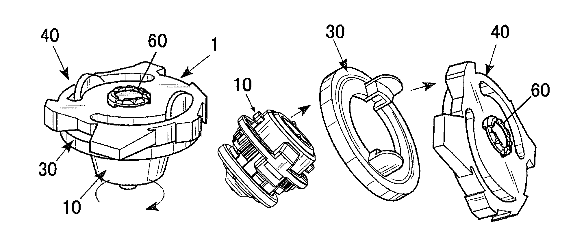
[0043] FIG. 1 illustrates how to play a toy top according to an embodiment of the present invention;
[0044] FIG. 2 is an exploded perspective view of the toy top according to the embodiment;
[0045] FIG. 3 is an exploded cross-sectional perspective view of the toy top according to the embodiment;
[0046] FIG. 4A and FIG. 4B are exploded perspective views of a shaft portion of the toy top according to the embodiment;
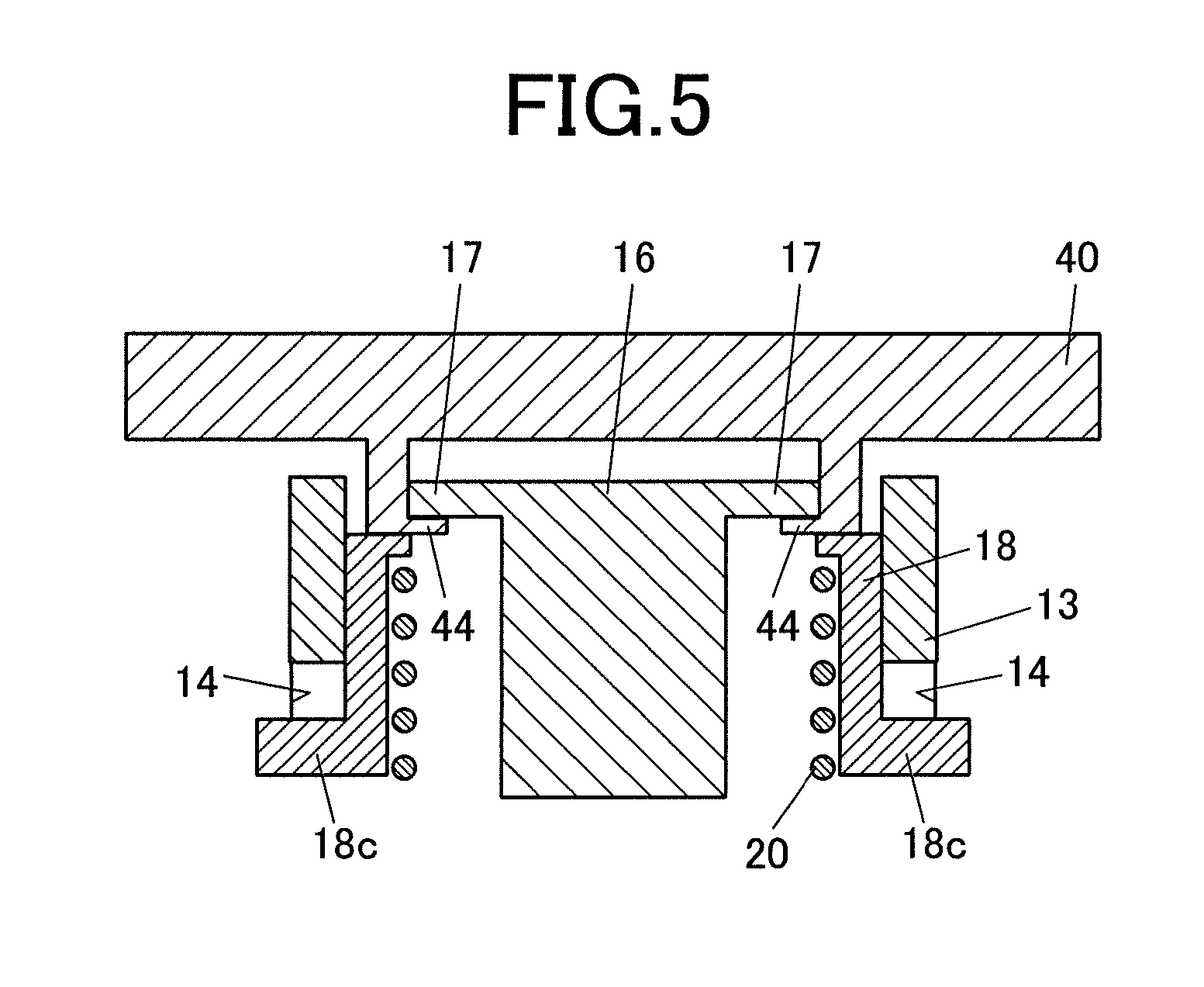
[0047] FIG. 5 is a schematic cross-sectional view of an upper shaft portion of the shaft portion of the toy top according to the embodiment, illustrating an assembled engagement thereof;
[0048] FIG. 6A to FIG. 6C are perspective views of an example of an additional part of the shaft portion of the toy top according to the embodiment;
[0049] FIG. 6D is a perspective view of an example of an adjusting member that is composed of the additional part in FIG. 6A to FIG. 6C and a supporting part attached thereto;
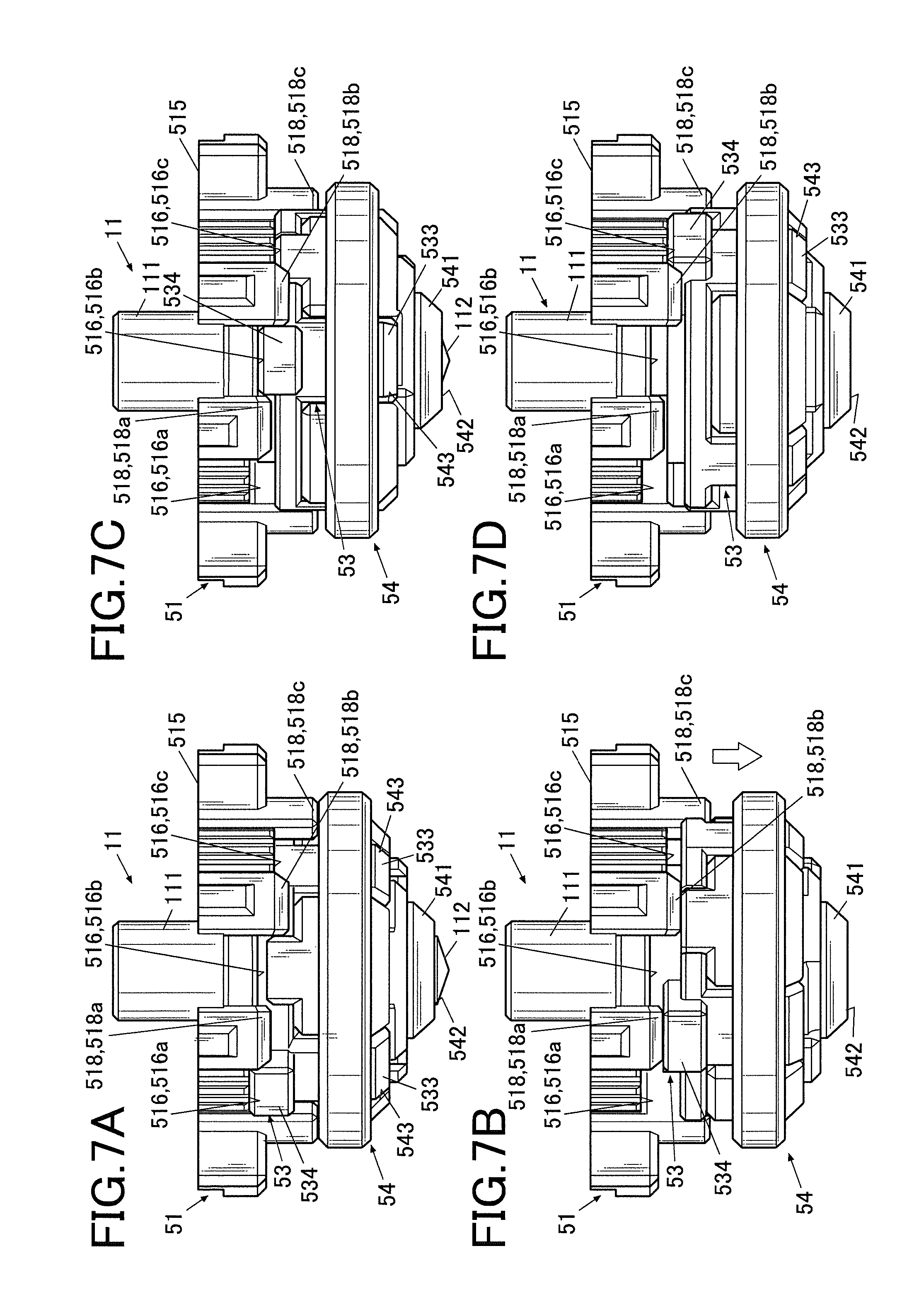
[0050] FIG. 7A to FIG. 7D are side views of a main part of the adjusting member in FIG. 6 D engaged with a step forming member;
[0051] FIG. 8A to FIG. 8C are perspective views of a variation of the additional part of the shaft portion of the toy top according to the embodiment;
[0052] FIG. 8D is a perspective view of an example of the adjusting member composed of the additional part in FIG. 8A to FIG. 8C and the supporting part attached thereto;
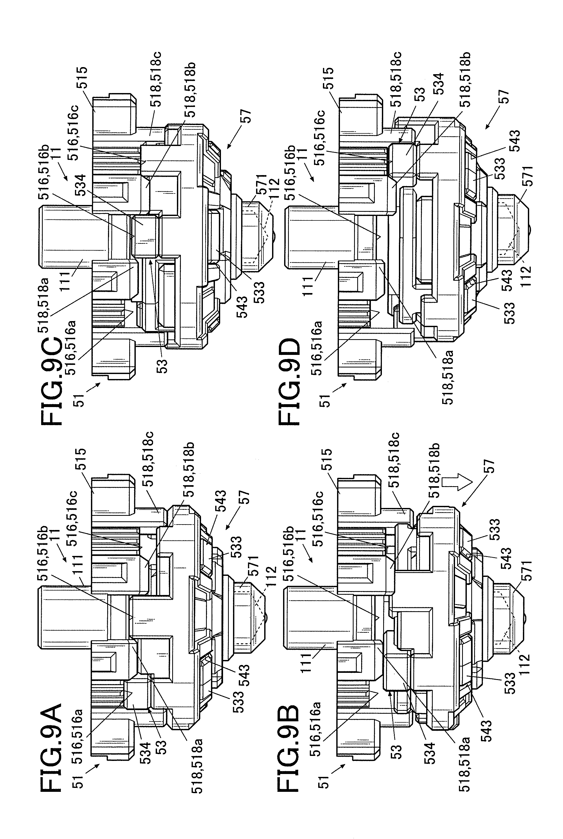
[0053] FIG. 9A to FIG. 9D are side views of a main part of the adjusting member in FIG. 8D engaged with the step forming member; and
[0054] FIG. 10 is a perspective view of an example of a launcher for spinning the toy top of the embodiment.
DETAILED DESCRIPTION
[0055] Hereinafter, an embodiment of the present invention will be described with reference to the drawings. Though various technical limitations which are preferable to perform the present invention are included in the after-mentioned embodiment, the scope of the invention is not limited to the following embodiment and the illustrated examples.
Overall Configuration
[0056] FIG. 1 illustrates how to play a toy top according to an embodiment of the present invention, FIG. 2 is an exploded perspective view of the toy top according to the embodiment, and FIG. 3 is an exploded cross-sectional perspective view of a shaft portion, a body and a performance changing ring of the toy top according to the embodiment. As used herein, the terms up-down, right-left and front-rear refer respectively to the directions as illustrated in FIG. 2 and FIG. 3.
[0057] The toy top 1 of this embodiment can be used for so-called battle games. Specifically, the toy top 1 can be used for a battle game which a player wins when an opponent toy top 1 is disassembled as illustrated in the right side of FIG. 1 by an impact force of a collision between the toy tops.
[0058] As illustrated in FIG. 2, the toy top 1 includes a shaft portion 10 that constitutes a lower structure to serve as a driver, a performance changing ring 30 and a body 40 that constitute an upper structure as a layer.
Detailed Configuration
1. Shaft Portion 10
[0059] FIG. 4A is an exploded perspective view from above of the shaft portion according to the embodiment, and FIG. 4B is an exploded perspective view from below of the shaft portion according to the embodiment.
[0060] As illustrated in FIG. 2 to FIG. 4B, the shaft portion 10 includes a spinning shaft 11 at a lower end, a flange 12 at a center part in the up-down direction, and a cylinder 13 at an upper part.
[0061] The flange 12 and the cylinder 13 are integrally formed with each other to constitute an upper shaft portion. Screw holes (not shown) are formed in the flange 12 and the cylinder 13, and a screws 10a (see FIG. 4A and FIG. 4B) are inserted in the screw holes of the flange 12 and the cylinder 13 so as to fix the upper shaft portion to a lower shaft portion.
[0062] First, the configuration of the upper shaft portion will be described.
[0063] In each of the flange 12 and the cylinder 13, two holes 14 are mutually opposed in the right-left direction across the axis (center axis) of the spinning shaft 11 (see FIG. 2 and FIG. 4A).
[0064] In the cylinder 13, two protrusions 15 are mutually opposed in the front-rear direction across the axis of the spinning shaft 11. Outer faces of the protrusions 15 are flush with an outer circumferential face of the flange 12.
[0065] FIG. 5 is a schematic cross-sectional view of the upper shaft portion, illustrating an assembled engagement thereof.
[0066] As illustrated in FIG. 3 and FIG. 5, a cylindrical pillar 16 stands inside the cylinder 13.
[0067] An upper end of the cylindrical pillar 16 is higher than an upper end of the cylinder 13. However, the position is not particularly limited. At the upper end of the cylindrical pillar 16, two hooks (engaging parts) 17 protrude outward in the radial direction, which are mutually opposed in the right-left direction across the axis of the spinning shaft 11.
[0068] At a lower end of the cylindrical pillar 16 corresponding to the center axis of the spinning shaft 11, a hole 16a (see FIG. 4B) is formed. The shape of the hole 16a corresponds to the shape of a cylinder 514 of a step forming member 51 (described later), and the cylinder 514 is inserted in the hole 16a when the lower shaft portion is attached to the upper shaft portion.
[0069] At the lower end of the cylindrical pillar 16 corresponding to the screw holes (not shown) of the flange 12 and the cylinder 13, holes 16c are formed. The above-described screws 10a are inserted in the screw holes through through holes 513 of the step forming member 51 (described below) and the holes 16c so as to fix the lower shaft portion to the upper shaft portion.
[0070] The shaft portion 10 also includes a cylindrical pressing member 18 around the cylindrical pillar 16 and inside the cylinder 13.
[0071] At a lower end of an outer circumference of the pressing member 18, two legs 18c are mutually opposed in the right-left direction across the axis of the spinning shaft 11 as illustrated in FIG. 2 to FIG. 5. The pressing member 18 is biased upward by a spring 20. The pressing member 18 is disposed so that upward movement of the legs 18c is restricted by upper edges of the holes 14. In an ordinary engagement, the upper end of the pressing member 18 is located slightly higher than the upper end of the cylinder 13.
[0072] On a top upper face of the pressing member 18, two ridges (protrusions) 21 extend in the radial direction, which are mutually opposed in the front-rear direction across the spinning shaft 11.
[0073] Next, the configuration of the lower shaft portion will be described.
[0074] The lower shaft portion includes the spinning shaft (see FIG. 4A, FIG. 4B and FIG. 6D), the step forming member 51 (see FIG. 4A and FIG. 4B) and an adjusting member 52 (see FIG. 6D).
[0075] In the spinning shaft 11, a shaft main body 111 is disposed at an axial center. The shaft main body 111 includes a shaft tip 112 at a lower tip. The embodiment illustrates an example in which the shaft tip 112 has a conical shape (e.g. see FIG. 4B). However, the shaft tip 112 may have any shape such as a simple rod or a rounded tip.
[0076] The spinning shaft 11 further includes a flange 113 around the shaft main body 111 near the shaft tip 112.
[0077] Around a circumference of shaft main body 111, a coil spring 110 is disposed as a biasing member.
[0078] In the embodiment, a groove 114 is formed in an upper face of the flange 113 along the circumference of the shaft main body 111 as illustrated in FIG. 4A. An end of the coil spring 110 is disposed in the groove 114.
[0079] An upper part of the shaft main body 111 penetrates a supporting part 53 (described later) and is fixed on the step forming member 51. The coil spring 110 as a biasing member is disposed between the flange 113 of the spinning shaft 11 and an upper inner face of the supporting part 53 to bias (press) the supporting part 53 toward the step forming member 51.
[0080] The step forming member 51 includes a flat plate part 511 that is formed approximately in a disk shape, and an outer part 515 that is disposed along the outer circumferential edge of the flat plate part 511.
[0081] Approximately at a center of the flat plate part 511, a through hole 517 is formed. The through hole 517 is formed in the shape that corresponds to the shape of the upper part of the shaft main body 111 of the spinning shaft 11. The upper part of the shaft main body 111 penetrates the supporting part 53 and is press-fitted in the through hole 517 so that the spinning shaft 11 is fixed to the step forming member 51. The manner of fixing the shaft main body 111 of the spinning shaft 11 to the step forming member 51 is not limited to press-fitting. For example, the spinning shaft may be fixed by a screw or a bolt or by bonding.
[0082] In the flat plate part 511, two bumps 512 are mutually opposed in the right-left direction across the through hole 517 corresponding to the protrusions 15 of the upper shaft portion.
[0083] In the bumps 512, through holes 513 are formed corresponding to the screw holes of the upper shaft portion, in which screws 10a are inserted.
[0084] The lower shaft portion including the step forming member 51 is fixed to the upper shaft portion by the screws 10a that are inserted in the screw holes of the flange 12 and the cylinder 13 through the through hole 513.
[0085] On an upper face of the flat plate part 511, a cylinder 514 protrudes upward corresponding to the through hole 517. As described above, the cylinder 514 is fitted in the hole 16a of the cylindrical pillar 16 when the lower shaft portion is attached to the upper shaft portion.
[0086] The outer part 515 of the step forming member 51 projects both upward and downward from the flat plate part 511. At the lower projection of the outer part 515, an engaging part is disposed to engage the additional part 54 (described later) with the spinning shaft 11 at different positions in the axis direction.
[0087] In the embodiment, the engaging part are constituted by a plurality of recesses 516 (recesses 516a, 516b, 516c in FIG. 7) with different depths in the axis direction of the spinning shaft 11. The recesses 516a, 516b, 516c are arranged around the axis of the spinning shaft 11.
[0088] As described later, the recesses 516 (recesses 516a, 516b, 516c) as the engaging part engage with the additional part 54 (in the embodiment, projections 534 of a supporting part 53 that is movable in the axis direction of the spinning shaft 11 integrally with the additional part 54 and that together with the adjusting member 52 constitutes the additional part 54). Each of the recesses 516 has a width capable of engaging with the projections 534.
[0089] In the embodiment, two projections 534 are approximately mutually opposed across the axis of the spinning shaft 11, and each pair of recesses 516a, 516b, 516c are approximately mutually opposed across the axis of the spinning shaft 11 corresponding to the two projections 534.
[0090] In the embodiment, the projection 534 of the supporting part 53 is engaged with any pair of the recesses 516 (recesses 516a, 516b, 516c in FIG. 7) so that the attachment position in the axis direction of the additional part 54 is changeable.
[0091] In the illustrated example, the recesses 516a are the deepest in the axis direction of the spinning shaft 11, the recesses 516c are the shallowest in the axis direction of the spinning shaft 11, and the recesses 516b have an intermediate depth between the recesses 516a and the recesses 516c.
[0092] The shape, the depth in the axis direction of the spinning shaft 11, the number, the position and the like of the recesses 516 in the embodiment are merely an example and may be suitably changed. The step forming member 51 may have any number (step) of recesses with any shape that are located within the engageable range of the projections 534 of the supporting part 53.
[0093] In the embodiment, the adjusting member 52 includes the additional part and the supporting part 53 that is movable in the axis direction of the spinning shaft 11 integrally with the additional part.
[0094] It is preferred that the additional part is detachable from the shaft portion 10.
[0095] When the additional part is detachable, it is preferred that different types of exchangeable additional parts are provided so that the user can freely choose one to be attached to the shaft portion 10.
[0096] As described later, the attachment position in the axis direction of the spinning shaft 11 (attachment position in the height direction of the shaft portion 10) of the additional part of the embodiment can be readily changed only by turning it around the axis without detaching it from the shaft portion 10. Since the grounding engagement and the height of the shaft portion 10 are changeable according to change of the attachment position of the additional part, it is possible to readily make various modifications of the toy top. When different detachable additional parts are provided so that the additional part is suitably exchangeable, it is possible to make a wider variety of modifications of the toy top 1.
[0097] The embodiment is an example in which two different additional parts, an additional part 54 in FIG. 6A to FIG. 6D and an additional part 57 in FIG. 8A to FIG. 8D are provided, which are detachable from the shaft portion 10 and exchangeable from each other.
[0098] In the embodiment, the additional part 54 and the additional part 57 are different from each other only in their lower ends, and FIG. 2, FIG. 3, FIG. 4A and FIG. 4B illustrate only an example in which the additional part 54 is attached to the shaft portion 10.
[0099] It is not essential in the embodiment that the additional part is detachable from the shaft portion 10. Further, even when the additional part is detachable, it is not essential that exchangeable different additional parts are provided. For example, only one of the additional parts 54, 57 may be provided. When the additional part 54 or 57 is broken by repetitive use in games or the like, the broken additional part 54 or 57 may be detached and replaced with a new additional part 54 or 57 of the same type.
[0100] In the embodiment, the additional part 54 is configured such that the spinning shaft 11 can be inserted from the upper side, and the shaft tip 112 of the spinning shaft 11 can stick out downward. Further, the additional part 54 includes a ring 541 which is disposed to circumferentially surround at least the shaft tip 112 of the spinning shaft 11. The position of the ring 541 surrounding the spinning shaft 11 is changed according to change of the attachment position of the additional part 54. The projected length of the shaft tip 112 of the spinning shaft 11 is thus adjustable, and the ring 541 can contact the ground depending on the degree of projection of the shaft tip 112 of the spinning shaft 11.
[0101] The configuration of the additional part 54 will be described in detail referring to FIG. 6A to FIG. 6D.
[0102] FIG. 6A is a perspective view from obliquely side of the additional part, FIG. 6B is a perspective view from obliquely above of the additional part, and FIG. 6C is a perspective view from obliquely below of the additional part. Further, FIG. 6D is a perspective view from obliquely above of the adjusting member that is composed of the additional part of FIG. 6A to FIG. 6C and the supporting part attached thereto.
[0103] As illustrated in FIG. 4A, FIG. 4B and FIG. 6A to FIG. 6C, the additional part 54 is formed in an approximately bowl or inverted conical overall shape. The additional part 54 is configured such that the spinning shaft 11 can be inserted from the upper side, and the shaft tip 112 or a bottom tip of the spinning shaft 11 can stick out downward.
[0104] Specifically, the ring 541 is disposed at a lower end of the additional part 54 to circumferentially surround at least the shaft tip 112 or the bottom tip of the spinning shaft 11. At a center of the ring 541, a through hole 542 is formed so that the shaft tip 112 of the spinning shaft 11 can be projected through the through hole 542.
[0105] As described above, the outer diameter of the flange 113 of the spinning shaft 11 is larger than the inner diameter of the through hole 542. Since the flange 113 cannot go through the through hole 542, the spinning shaft 11 is held inside the ring 541 so as not to come off from the additional part 54.
[0106] The position of the ring 541 surrounding the spinning shaft 11 is changed according to change of the attachment position of the additional part 54, which makes the degree of projection of the shaft tip 112 of the spinning shaft 11 adjustable. Further, the ring 541 can contact the ground depending on the degree of projection of the shaft tip 112 of the spinning shaft 11.
[0107] That is, as the attachment position of the additional part 54 ascends relative to the spinning shaft 11, the shaft tip 112 of the spinning shaft 11 projects accordingly from the through hole 542 (e.g. see FIG. 7A and FIG. 7C). On the contrary, as the attachment position of the additional part 54 to the spinning shaft 11 descends relative to the spinning shaft 11, the position of the ring 541 surrounding the spinning shaft 11 descends (toward a bottom tip of the spinning shaft 11) accordingly. When a lower end of the ring 541 becomes equal to or lower than the shaft tip 112 of the spinning shaft 11 (e.g. see FIG. 7D), the ring 541 contacts the ground as well as or instead of the shaft tip 112 of the spinning shaft 11.
[0108] FIG. 6A and the like illustrate an example in which the ring 541 is formed in a tapered shape in a side view, having an outer diameter that decreases toward the bottom tip of the shaft portion 10. However, the shape of the ring 541 is not limited to the illustrated example. By changing the outer shape of the ring 541, it is possible to change the action of the toy top 1 when the ring 541 contacts the ground.
[0109] On a bottom of the additional part 54, a plurality of engaging holes 543 surrounds the ring 541.
[0110] The engaging holes 543 receive and engage with engaging legs 533 (described later) of the supporting part 53 when the shaft portion 10 is assembled. In the embodiment, four engaging holes 543 are formed at substantially the same intervals so as to be at substantially the same distance in the front, rear, left and right directions from ring 541 in accordance with the number and position of the engaging legs 533 of the supporting part 53.
[0111] In the engaging holes 543, steps 543a are formed. When the engaging legs 533 are inserted in the supporting part 53, hooks 533a at tips of the engaging legs 533 engage with the steps 543a.
[0112] When the engaging legs 533 of the supporting part 53 are inserted in the engaging holes 543 so that the hooks 533a engage with the steps 543a, the additional part 54 and the supporting part 53 engages and integrates with each other to form the adjusting member 52.
[0113] The shape, number, position and the like of the engaging holes 543 correspond to those of the engaging legs 533 of the supporting part 53 but are not limited to the illustrated example.
[0114] In a bottom of the additional part 54, a plurality of engaging holes 544 are formed at a different position from the engaging holes 543. In the embodiment, two engaging holes 544 are approximately mutually opposed across the ring 541.
[0115] In the embodiment, the engagement between the additional part 54 and the supporting part 53 is released by inserting nails or jigs into the engaging holes 544 and pulling the additional part 54 downward. The additional part 54 can thus be detached from the shaft portion 10.
[0116] The shape, number, position and the like of the engaging holes 544 are not limited to the illustrated example.
[0117] The method of detaching the additional part 54 by releasing the engagement between the additional part 54 and the supporting part 53 is not limited to the above-described example, and other jigs and methods may be used instead.
[0118] On the upper face of the additional part 54 of the embodiment, protrusions 545 are formed corresponding to recesses 535 (described later) of the supporting part 53.
[0119] The embodiment illustrates an example in which two protrusions 545 are approximately mutually opposed across the axis of the spinning shaft 11. However, the shape, number, position and the like of the protrusions 545 are not limited to the illustrated example.
[0120] Next, the configuration of the additional part 57 will be described in detail referring to FIG. 8A to FIG. 8D. Unlike FIG. 6D, the spinning shaft 11 is not shown in FIG. 8D.
[0121] FIG. 8A is a perspective view from obliquely side of the additional part, FIG. 8B is a perspective view from obliquely above of the additional part, and FIG. 8C is a perspective view from obliquely below of the additional part. Further, FIG. 8D is a perspective view from obliquely above of the adjusting member that is composed of the additional part in FIG. 8A to FIG. 8C and the supporting part attached thereto.
[0122] As illustrated in FIG. 8A to FIG. 8C, the additional part 57 is formed in a bowl or inverted conical overall shape as with the additional part 54, and the spinning shaft 11 can be inserted therein from the upper side.
[0123] Different from the additional part 54, the additional part 57 includes a covering part 571 at a lower end, which covers the shaft tip 112 or the bottom tip of the spinning shaft 11 from the lower side to form a new spinning shaft. The shaft tip 112 of the spinning shaft 11 is disposed inside the covering part 571 and is not exposed to the outside.
[0124] In the covering part 571, a recess 572 is formed to receive the shaft tip 112 (see FIG. 8B).
[0125] The additional part 57 changes the height of the shaft portion 10 according to change of the attachment position thereof.
[0126] That is, when the additional part 57 is at the highest attachment position to the spinning shaft 11, an inner face of the covering part 571 (i.e. an inner face of the recess 572) is completely or almost in contact with the shaft tip 112 of the spinning shaft 11, and the covering part 571 and the shaft tip 112 are approximately at the same height (e.g. see FIG. 9A). As the attachment position of the additional part 57 to the spinning shaft 11 descends, the inner face of the covering part 571 (inner face of the recess 572) separates away from the shaft tip 112 of the spinning shaft 11 so that the length in the axis direction of the shaft portion 10 increases (see FIG. 9D). In this way, the overall height of the toy top 1 is greater when the outer face of the covering part 571 of the additional part 57 is in contact with the ground than when the shaft tip 112 of the spinning shaft 11 is in contact with the ground. This allows changing the center of gravity of the toy top 1 and thereby changing the action of the toy top 1.
[0127] FIG. 8A, FIG. 8C and the like illustrate an example in which the covering part 571 has a tapered shape in a side view, having an outer diameter that decreases toward the bottom tip of the shaft portion 10. However, the shape of the covering part 571 is not limited to the illustrated example. By changing the outer shape of the covering part 571, it is possible to change the action of the toy top 1 when the covering part 571 contacts the ground.
[0128] Since the other configuration of the additional part 57 is the same as that of the additional part 54, the same reference signs are denoted to the same parts, and the description thereof is omitted.
[0129] The supporting part 53 includes an approximately disk-shaped flat plate part 531, and a through hole 532 through which the spinning shaft 11 is inserted is formed approximately at a center of the flat plate part 531. The supporting part 53 is disposed on the additional part 54 such that an upper part of the shaft main body 111 of the spinning shaft 11 projects upward from the through hole 532, and the flange 113 of the spinning shaft 11 is intervened between the additional part 54 and the supporting part 53.
[0130] As described above, the supporting part 53 is biased (pressed) upward (i.e. against the upper shaft portion and the step forming member 51 fixed thereto) by the coil spring 110 that is disposed around the spinning shaft 11.
[0131] In the circumferential face of the flat plate part 531 of the supporting part 53, two recesses 535 are approximately mutually opposed across the axis of the spinning shaft 11. The above-described protrusions 545 on the upper face of the additional part 54 are fitted in the recesses 535. This prevents the supporting part 53 and the additional part 54 from moving relative to each other in the spinning direction (circumferential direction of the spinning axis).
[0132] The shape, number, position and the like of the recesses 535 correspond to the protrusions 545 of the additional part 54 but are not limited to the illustrated example.
[0133] At a lower end of the flat plate part 531 of the supporting part 53, the four engaging legs 533 stand vertically downward.
[0134] The engaging legs 533 are disposed corresponding to the engaging holes 543 to engage with the above-descried engaging holes 543 of the additional part.
[0135] The engaging legs 533, which are rather elastic, include respective hooks 533a that protrude toward the axis (center axis).
[0136] To assemble the toy top 1, the engaging legs 533 are inserted into the engaging holes 543 of the additional part 54 to engage the hooks 533a with the steps 543a of the additional part 54. The engaging legs 533 thus hold the additional part 54 from four directions. As a result, the additional part 54 and the supporting part 53 are engaged with each other to work integrally.
[0137] The shape, number, position and the like of the engaging legs 533 correspond to those of the engaging holes 543 of the additional part 54 but are not limited to the illustrated example.
[0138] On an upper face of the flat plate part 531 of the supporting part 53, projections 534 are provided as an engaging part that can fit in the recesses 516 (recesses 516a, 516b, 516c) of the shaft portion 10 (step forming member 51 in the embodiment).
[0139] In the embodiment, each pair of recesses 516 (recesses 516a, 516b, 516c) are approximately mutually opposed across the axis of the spinning shaft 11 as described above. Corresponding to a pair of recesses 516a, 516b or 516c, two projections 534 are mutually opposed across the axis of the spinning shaft 11.
[0140] The shape, number, position and the like of the projections 534 correspond to the recesses 516a, 516b, 516c but are not limited to the illustrated example. For example, the recesses 516 (recesses 516a, 516b, 516c) may not be disposed as a pair that is mutually opposed across the axis of the spinning shaft 11. When a recess 516 (recesses 516a, 516b, 516c) is disposed at either side in the circumference of the step forming member 51, the projection 534 is also disposed only at the same side in the circumference of the supporting part 53.
2. Performance Changing Ring 30
[0141] In the embodiment, the performance changing ring 30 is constituted by a flywheel. The performance changing ring 30 has a plate shape. On a bottom face of the performance changing ring 30, an annular step 31 is formed as illustrated in FIG. 3 so that the flange 12 of the shaft portion 10 can be received therein from the lower side. On an upper face of the performance changing ring 30, two upward protrusions 32 are mutually opposed in the right-left direction across the axis of the spinning shaft 11 as illustrated in FIG. 2 and FIG. 3. In lower parts of the protrusions 32, recesses 33 are formed so that the protrusions 15 of the shaft portion 10 can be received therein from the lower side. On the upper face of the performance changing ring 30, tongues 34 extend upward along an outer side of the respective protrusions 32. The tongues 34 protrude higher than the protrusions 32. Instead of or integrally with the flywheel, the performance changing ring 30 may include a protrusion for attacking an opponent toy top 1 or a recess for averting an attack from an opponent toy top 1 on an outer circumferential face.
3. Body 40
[0142] The body 40 has a disk shape. As illustrated in FIG. 2, the body 40 includes a base 400 and a transparent cover 401 which has approximately the same shape as the base 400 in a plan view and to cover the body 400.
[0143] On an outer circumference of the body 40, an uneven portion 40a is formed. Further, at a center of the base 400, a round hole 41 is formed. The transparent cover 401 covers the base 400 except for the round hole 41 and arc slits 46 (described later). On a bottom face of the body 40, an annular recess 42 is formed so that the protrusions of the performance changing ring 30 can be received therein.
[0144] At a lower end of an inner circumferential face of an inner circumferential wall 43a that defines the annular recess 42, two hooks (engaging parts) 44 protrude inward in the radial direction, which are mutually opposed in the front-rear direction across the axis of the spinning shaft 11.
[0145] In a middle in the up-down direction of the inner circumferential face of the inner circumferential wall 43a, two protrusions 47 protrude inward in the radial direction, which are mutually opposed in the right-left direction across the axis of the spinning shaft 11.
[0146] On a lower end face of the inner circumferential wall 43a, two uneven portions 45 are mutually opposed in the right-left direction across the axis of the spinning shaft 11 in which ridges are successively formed to mesh with the ribs 21.
[0147] On a top wall 43b that define the annular recess 42 of the body 40, arc slits 46 are formed so that the tongues 34 of the performance changing ring 30 can be inserted therein from the lower side. The arc slits 46 have a length that allows the tongues 34 to move sufficiently.
4. Identifier 60
[0148] An identifier 60 is attached in the round hole 41. The identifier 60 is used to identify the toy top 1 or the player thereof.
[0149] To achieve the identification, identifiers 60 with different patterns and/or colors are provided in the embodiment, and the player selects one identifier 60 therefrom and attach it to the round hole 41 with grooves 60a and the protrusions 47 that serve as screw threads.
Assembling Method
[0150] Next, the assembling method of the toy top 1 will be described. The shaft portion 10 has been already assembled. Further, the identifier 60 has been already attached in the round hole 41.
[0151] First, the shaft portion 10 is fitted in the performance changing ring 30 such that the protrusions 15 of the shaft portion 10 mate with the recesses 33 of the performance changing ring 30. Subsequently, the assembly is brought toward the body 40 from the lower side. In this step, the tongues 34 of the performance changing ring 30 of the assembly are aligned with predetermined ends of the arc slits 46 of the body 40 (see FIG. 3). In this engagement, the hooks 17 of the shaft portion 10 do not overlap the hooks 44 of the body 40 in the up-down direction. This engagement is referred to as an engagement releasable engagement. Thereafter, the shaft portion 10 of the assembly is pushed toward the body 40. Then the performance changing ring 30 firstly abuts the bottom face of the body 40. Then, the spring 20 is compressed, and the hooks 17 of the shaft portion 10 are relatively pushed up higher than the hooks 44 of the body 40. Subsequently, the shaft portion 10 together with the performance changing ring 30 is turned relative to the body 40 until the tongues 34 reach the other ends opposite to the predetermined ends. This is a relative turn of the body 40 and the performance changing ring 30 with respect to the shaft portion 10. Then, the hooks 17 of the shaft portion 10 are vertically aligned with the hooks 44 of the body 40 as illustrated in FIG. 5. When the hand is removed from the shaft portion 10, the lower face of the hooks 17 of the shaft portion 10 abuts the upper face of the hooks 44 of the body 40 by the action of the biasing force of the spring 20.
[0152] This engagement, in which the bottom faces of the hooks 17 of the shaft portion 10 are in contact with the upper faces of the hooks 44 of the body 40, is referred to as an engaged engagement. In this way, the shaft portion is coupled with the performance changing ring 30 and the body 40. The toy top 1 is thus assembled.
How to Change Spinning Characteristic
[0153] Next, a method to change the spinning characteristic when the additional part 54 is attached to the shaft portion 10 will be described referring to FIG. 7A to FIG. 7D.
[0154] When the projections 534 of the supporting part 53 are engaged with any pair of recesses 516 (e.g. recesses 516a), the supporting part 53 is biased upward by the coil spring 110 so that the projections 534 remain being fit in the recesses 516 and do not move in an ordinary engagement.
[0155] As described above, the recesses 516a are the deepest in the axis direction of the spinning shaft 11 in the embodiment. As illustrated in FIG. 7A, when the projections 534 of the supporting part 53 are engaged with the recesses 516a, the additional part 54 is at the highest attachment position in the axis direction, and the shaft tip 112 of the spinning shaft 11 protrudes the most from the hole 542 of the ring 541.
[0156] In this engagement, only the shaft tip 112 of the spinning shaft 11 contacts the ground when the toy top 1 spins vertically or almost vertically with respect to the ground surface. Only when the toy top 1 is largely inclined with respect to the ground surface, the ring 541 contacts the ground along with or instead of the shaft tip 112.
[0157] A user who wants to change the spinning characteristic of the toy top 1 temporarily pulls the adjusting member 52 downward (the direction indicated by the outlined arrow in FIG. 7B) as illustrated in FIG. 7B. Then, while pulling the adjusting member 52 down to the height at which the projections 534 can cross over the bumps 518 (518a) defining the recesses 516a, he/she turns the adjusting member 52 around the axis (to the right in FIG. 7A to FIG. 7D in the embodiment).
[0158] When the user releases his/her hand from the adjusting member 52 after he/she turns the adjusting member 52 until the projections 534 cross over the bumps 518 (518a) of the recesses 516a to reach another pair of recesses 516 (e.g. the recesses 516b next to the recesses 516a at the right in FIG. 7A to FIG. 7D), the adjusting member 52 including the supporting part 53 is pushed up by the biasing force (pushing force) of the coil spring 110 so that the projections 534 fit in the recesses 516b as illustrated in FIG. 7C.
[0159] When the protrusions 534 of the supporting part 53 are engaged with the recesses 516 as illustrated in FIG. 7C, the additional part 54 is at a slightly lower attachment position in the axis direction by the difference of depth of the recesses 516b since the recesses 516b are shallower in the axis direction of the spinning shaft 11 than the recesses 516a. Accordingly, the shaft tip 112 of the spinning shaft 11 protrudes slightly less from the hole 542 of the ring 541.
[0160] In this engagement, when the toy top 1 spins vertically or almost vertically with respect to the ground surface, only the shaft tip 112 of the spinning shaft 11 contacts the ground. However, when the toy top 1 is even slightly inclined with respect to the ground surface, the ring 541 contacts the ground along with or instead of the shaft tip 112.
[0161] The user can further temporarily pulls the adjusting member 52 downward (the direction indicated by the outlined arrow in FIG. 7B) as illustrated in FIG. 7B, turns the adjusting member 52 around the axis (to the right in FIG. 7A to FIG. 7D in the embodiment) until the projections 534 cross over the bumps 518 (518b) defining the recesses 516b to reach another pair of recesses 516 (e.g. recesses 516c next to the recesses 516b at the right in FIG. 7A to FIG. 7D), and releases his/her hand from the adjusting member 52. Then, the adjusting member 52 including the supporting part 53 is pulled up by the biasing force (pressing force) of the coil spring 110 so that the projections 534 fit in the recesses 516c as illustrated in FIG. 7D.
[0162] The recesses 516c is further deeper in the axis direction of the spinning shaft 11 than the recesses 516b. When the projections 534 are fitted in the recesses 516c, the additional part 54 is at a slightly lower attachment position in the axis direction by the difference of depth of the recesses 516c as illustrated in FIG. 7D. Accordingly, the shaft tip 112 of the spinning shaft 11 does not protrude from the hole 542 of the ring 541.
[0163] In this engagement, only the ring 541 contacts the ground regardless of the inclination of the spinning toy top 1.
[0164] When the user further wants to fit the projections 534 into another pair of recesses 516 other than the recesses 516c, he/she can turn the adjusting member 52 until the projections 534 cross over the bumps 518 (518c) defining the recesses 516c to reach the recesses 516a next to the recesses 516c at the right. Alternatively, the user can turn the adjusting member 52 in the opposite direction to the left until the projections 534 cross over the bump 518 (518b) defining the recesses 516b to return to the recesses 516b next to the recesses 516c at the left.
[0165] The toy top 1 spins stably when the shaft tip 112 having a small contact area contacts the ground. However, when the ring 541 having a large contact area contacts the ground, the action becomes irregular, such as an irregular change of the spinning angle and a large movement of the toy top 1. This can result in an unexpected attack or the like on an opponent toy top.
[0166] As illustrated in FIG. 7A to FIG. 7D, the embodiment illustrates an example in which an adjustment can be made by changing the position (type) of the recesses 516 that is engaged with the projections 534 of the adjusting member 52, in which the engagement can be selected from among three levels ranging from the engagement in which the shaft tip 112 of the spinning shaft 11 protrudes from the hole 542 of the ring 541 to the state in which the shaft tip 112 does not protrude from the hole 542 of the ring 541. However, the adjustable levels are not limited to the illustrated three levels.
[0167] For example, another pair of recesses 516 that is yet shallower than the recesses 516c in FIG. 7D may be provided so that the additional part 54 can be at a yet lower attachment position at which the lower end of the ring 541 is lower than the shaft tip 112 of the spinning shaft 11.
[0168] In this configuration, it is possible to change the height of the shaft portion 10 according to change of the attachment position of the additional part 54 (i.e. to increase the length of the shaft portion 10 compared to the state in which the shaft tip 112 of the spinning shaft 11 contacts the ground).
[0169] Next, a method to change the spinning characteristic when the additional part 57 is attached to the shaft portion 10 will be described referring to FIG. 9A to FIG. 9D.
[0170] In the case in which the additional part 57 is attached to the shaft portion 10, the additional part 57 is at the highest attachment position in the axis direction when the projections 534 of the supporting part 53 are engaged with the recesses 516a that are deepest in the axis direction of the spinning shaft 11. In this state, the shaft tip 112 of the spinning shaft 11 is in contact with an inner side of a lower end of the covering part 571 of the additional part 57 as illustrated in FIG. 9A, and the length of the shaft portion 10 of the toy top 1 is the shortest.
[0171] A user who wants to change the spinning characteristic of the toy top 1 temporarily pulls the adjusting member 52 downward (in the direction indicated by the outlined arrow in FIG. 9B) as illustrated in FIG. 9B. Then, while pulling the adjusting member 52 down to the height at which the projections 534 can cross over the bumps 518 (518a) defining the recesses 516a, he/she turns the adjusting member 52 around the axis (to the right in FIG. 9A to FIG. 9D in the embodiment).
[0172] When the user releases his/her hand from the adjusting member 52 after he/she turns the adjusting member 52 until the projections 534 cross over the bumps 518 (518a) of the recesses 516a to reach another pair of recesses 516 (e.g. the recesses 516b next to the recesses 516a at the right in FIG. 9A to FIG. 9D), the adjusting member 52 including the supporting part 53 is pushed up by the biasing force (pushing force) of the coil spring 110 so that the projections 534 fit in the recesses 516b as illustrated in FIG. 9C.
[0173] Since the recesses 516b are shallower in the axis direction of the spinning shaft 11 than the recesses 516a, the additional part 54 is at a slightly lower attachment position in the axis direction by the difference of depth of the recesses 516b when the protrusions 534 of the supporting part 53 are engaged with the recesses 516b as illustrated in FIG. 9C. Accordingly, the lower end of the covering part 571 is at a slightly lower position than the shaft tip 112 of the spinning shaft 11.
[0174] In this state, the shaft portion 10 of the toy top 1 is longer, which changes the spinning characteristic of the toy top 1.
[0175] Further, when the user further performs the same process so that the protrusions 534 fit in the recesses 516c, the additional part 54 is at a lower attachment position in the axis direction by the difference of depth of the recesses 516b when the protrusions 534 of the supporting part 53 are engaged with the recesses 516c as illustrated in FIG. 9D, since the recesses 516c are the shallowest in the axis direction of the spinning shaft 11. Accordingly, the lower end of the covering part 571 is at a slightly lower position than the shaft tip 112 of the spinning shaft 11.
[0176] In this state, the shaft portion 10 of the toy top 1 is further longer.
[0177] When the length of the shaft portion 10 is changed, the spinning characteristic is also changed since the center of gravity of the toy top 1 is changed. This can result in an unexpected attack or the like on an opponent toy top.
How to Play
[0178] Next, an example of how to play the toy top 1 will be described.
[0179] In this example, a player spins a toy top 1 and forces it to battle with an opponent toy top 1.
[0180] In such cases, the launcher 90 as illustrated in FIG. is used to apply a spinning force to the toy top 1. The launcher 90 includes a disk (not shown) therein that is biased in a certain spinning direction by a spiral spring (not shown). The launcher 90 is configured such that when an operating member, such as a string or rack of teeth (not shown) is pulled by a handle 91 while a spiral spring (not shown) biases the disk in a certain rotational direction, the disk is rotated, and a top holder 93 is rotated accordingly. The rotation of the top holder 93 is transmitted to the toy top 1 through a fork 94 that protrudes downward, so that the toy top 1 is rotated. When the fork 94 is inserted in the arc slits 46 (see FIG. 3) of the body 90, and when the handle 91 of the launcher 90 is completely pulled out of the launcher 90, the disk and the top holder 93 stop rotating while the toy top 1 continues rotating by the action of its inertial force. As a result, the toy top 1 descends from the top holder 93 following the inclined faces 94a of the fork 94. In FIG. 10, the reference sign 92 designates a rod that is retractable into the top holder 93. When the toy top 1 is set to the top holder 93, the rod 92 is pushed by an upper face of the toy top 1 and retracted into the top holder 93. For example, the rod 92 is used to detect attachment/detachment of the toy top 1.
[0181] The toy top 1 thus launched spins in a predetermined battle field. When the toy top 1 collides with an opponent toy top 1, the impact or friction of the collision produces a force that acts on the body 40 in the direction opposite to the spinning direction of the shaft portion 10 and the performance changing ring 30, and the body 40 thereby relatively turns in the direction opposite to the spinning direction of the shaft portion 10 and the performance changing ring 30.
[0182] Then, the ribs 21 mesh with the uneven portions 45 of the body 40. Since the biasing force of the spring 20 acts on the ribs 21, every time an impact force of a collision is applied, the body 40 turns relative to the shaft portion 10 to change the mesh position. When the ribs 21 eventually reach the engagement releasing position, the hooks 44 of the body 40 are released from the hooks 17 of the shaft portion 10 so that the body 40 separates from the shaft portion 10 by the biasing force of the spring 20 that acts on the ridges 21. As a result, the toy top 1 is disassembled as illustrated in the right side of FIG. 1.
ADVANTAGEOUS EFFECTS OF THE EMBODIMENT
[0183] As described above, the toy top 1 according to the embodiment includes: the shaft portion 10; the additional part 54 which is attached to the shaft portion 10 movably in the axis direction of the spinning shaft 11 of the shaft portion 10; and an engaging part (the recesses 516 and the protrusions 534 in the embodiment) which engages the additional part 54 with the spinning shaft 11 at different positions in the axis direction, wherein the attachment position of the additional part 54 is changeable by changing the engagement of the additional part 54 by the engaging part (recesses 516 and projections 534).
[0184] This enables readily switching the configuration of the grounding part of the toy top 1 between multiple levels to change the center of gravity or the spinning characteristic of the toy top 1. Therefore, it is possible to enjoy various attacks and battle games that are rich in variation with the same toy top 1.
[0185] In the embodiment, the additional part 54 is detachable from the shaft portion 10. Therefore, different additional parts (the additional parts 54, 57 in the embodiment) can be provided so that a user can select a suitable additional part for a desired spinning characteristic. Since it is possible to replace the additional part with another additional part having a different function (e.g. the additional part 54 that can change the grounding state of the bottom tip of the shaft portion 10 according to the attachment position, and the additional part 57 that can change the height (length) of the shaft portion 10 according to the attachment position), it is possible to modify the same toy top 1 into various toy tops that can perform different characteristic attacks, i.e. to make a wide variation of modifications, in a simple process. Therefore, a toy top that can perform various attacks on an opponent toy top can be achieved.
[0186] Further, the additional parts 54, 57 may be separately provided as consumable parts. For example, when the additional part 54 or 57 is broken by a collision with an opponent toy top or the like, it is possible to remove only the broken additional part 54 or 57 to replace it with a new one. Therefore, the toy top 1 can be used for a long time.
[0187] In the embodiment, the degree of protrusion of the shaft tip 112 of the spinning shaft 11 is adjustable only by changing the attachment position of the additional part 54. Therefore, it is possible to readily switch the grounding pattern according to the degree of protrusion of the bottom tip of the spinning shaft between (i) the state in which only the shaft tip 112 of the spinning shaft 11 contacts the ground, (ii) the state in which both the shaft tip 112 of the spinning shaft 11 and the ring 541 contact the ground, and (iii) the state in which only the ring 541 contacts the ground.
[0188] Since the ground contact area changes according to the part that contacts the ground, it is possible to change the spinning characteristic of the toy top 1 so as to perform various attacks on an opponent toy top.
[0189] In the embodiment, the additional part 57 includes the covering part 571 that forms a new spinning shaft. This enables readily changing the height of the shaft portion 10 only by changing the attachment position of the additional part 57.
[0190] Changing the height of the shaft portion 10 can change the center of gravity of the toy top 1 accordingly. Therefore, the toy top 1 that can perform various attacks on an opponent toy top can be achieved.
[0191] In the embodiment, the engaging part for changing the attachment position of the additional part 54 is constituted by the recesses 516 and the protrusions 534 that fit in the recesses 516.
[0192] This enables readily changing the attachment position of the additional part 54 only by changing the fitting position between the recesses 516 and the protrusions 534 so as to change the spinning characteristic of the toy top 1. Therefore, everyone can readily enjoy battle games that are rich in variation.
[0193] Further, since the engagement is established by meshing the recesses 516 with the protrusions 634, the position in the axis direction of the additional part 54 relative to the spinning shaft 11 is not changed even when the toy top 1 spins or vigorously collides with an opponent toy top, and the configuration preset by a user before starting a game can be maintained.
[0194] In the embodiment, the recesses 516 are formed in the step forming member 51 of the shaft portion 10 around the spinning shaft 11 at different positions in the axis direction, and the protrusions 534 that can selectively fit in any pair of the recesses 516 are formed in the supporting part 53 of the adjusting member 52.
[0195] This enables readily changing the attachment position of the additional part 54 by shifting the adjusting member 52 around the spinning shaft 11. Therefore, everyone can readily enjoy battle games that are rich in variation.
[0196] In the embodiment, the toy top 1 includes a coil spring 110 as a biasing member which applies a biasing force to maintain the engagement of the additional part 54.
[0197] This can prevent the additional part 54 from being deviated from the attachment position or being released from the engagement even when the toy top 1 collides with another toy top during a game.
ALTERNATE EMBODIMENTS OF THE INVENTION
[0198] While an embodiment of the present invention is described, the present invention is not limited to the above-described embodiment, and it should be understood well that various changes can be made without departing from the features of the present invention.
[0199] For example, the embodiment illustrates an example in which the engaging part is composed of recesses 516 that are formed in the outer part 515 of the step forming member 51 and the protrusions 534 of the supporting part to be fitted therein. However, the engaging part is not limited to the recesses 516 and the protrusions 534 but may be constituted by any part that allows changing the attachment position in the axis direction of the additional part 54.
[0200] For example, screw threads that can mutually fit may be formed respectively in an outer circumferential face of the shaft portion 10 and an inter circumferential face of the additional part 54 or 57 (or the adjusting member 52 including the additional part), and the additional part 54 or 57 (or the adjusting member including the additional part) may be screwed around the shaft portion 10. In this configuration, the engagement position in the axis direction of the adjusting member 52 including the additional part 54 or 57 can be gradually changed according to the screwed position (degree of being screwed).
[0201] Further, instead of the recesses, the changeable engagement position of the engaging part can be achieved only by abutment of the additional part 54 or 57, e.g. by a stepped part or the like.
[0202] The embodiment illustrates an example in which the adjusting member 52 including the additional part 54 is turned with respect to the shaft portion 10 so that the protrusions 534 fit in the recesses 516 (engaging part). However, the method to switch the engaging part may not be turning the adjusting member 52.
[0203] Further, the engaging part is not limited to the combination of the recesses 516 of the shaft portion 10 and the protrusions 534 of the adjusting member 52 including the additional part 54. For example, a protrusion may be formed in the shaft portion 10 while recesses may be formed in the adjusting member 52 including the additional part 54 in contrast to the embodiment.
[0204] The engaging part may not have the configuration of fitting a protrusion in recesses. For example, the adjusting member 52 including the additional part 54 or 57 may be engaged with the shaft portion 10 by hooking a hook or the like to a recess or a hole.
[0205] Alternatively, for example, stepped protrusions may formed at different heights around the outer circumference of the shaft portion 10, and the adjusting member 52 including the additional part 54 or 57 may be pressed against the protrusions by a biasing force of a biasing member such as a spring.
[0206] In the embodiment, the supporting part 53 that moves integrally with the additional part 54 or 57 is provided in addition to the additional part 54 or 57, and the attachment position in the axis direction is changeable by changing engagement of the adjusting member 52 composed of the additional parts 54 or 57 and the supporting part 53 with the shaft portion 10. However, the engaging part may not be formed in the step forming member 51 and the supporting part 53, and the supporting part 53 is not an essential component.
[0207] It is only necessary that the engaging part be formed in the shaft portion 10 and the additional part 54 or 57 or the like that is movable in the axis direction of the spinning shaft 11. For example, a protrusion or the like may be formed in the additional part 54 or 57 as the engaging part that engages with the engaging part (e.g. recesses) of the shaft portion 10.
[0208] The entire disclosure of Japanese patent application No. 2017-201195, filed on Oct. 17, 2017, is incorporated herein by reference in its entirety.
* * * * *
D00000
D00001
D00002
D00003
D00004
D00005
D00006
D00007
D00008
D00009
D00010
XML
uspto.report is an independent third-party trademark research tool that is not affiliated, endorsed, or sponsored by the United States Patent and Trademark Office (USPTO) or any other governmental organization. The information provided by uspto.report is based on publicly available data at the time of writing and is intended for informational purposes only.
While we strive to provide accurate and up-to-date information, we do not guarantee the accuracy, completeness, reliability, or suitability of the information displayed on this site. The use of this site is at your own risk. Any reliance you place on such information is therefore strictly at your own risk.
All official trademark data, including owner information, should be verified by visiting the official USPTO website at www.uspto.gov. This site is not intended to replace professional legal advice and should not be used as a substitute for consulting with a legal professional who is knowledgeable about trademark law.