Computing Device Replication Using File System Change Detection Methods And Systems
Parab; Nitin ; et al.
U.S. patent application number 14/977614 was filed with the patent office on 2019-04-11 for computing device replication using file system change detection methods and systems. The applicant listed for this patent is eFolder, Inc.. Invention is credited to Aaron Brown, Nitin Parab, Joshua Schwartz, Shashi Sharma.
| Application Number | 20190108103 14/977614 |
| Document ID | / |
| Family ID | 58409284 |
| Filed Date | 2019-04-11 |


| United States Patent Application | 20190108103 |
| Kind Code | A9 |
| Parab; Nitin ; et al. | April 11, 2019 |
COMPUTING DEVICE REPLICATION USING FILE SYSTEM CHANGE DETECTION METHODS AND SYSTEMS
Abstract
Computing device file system change detection and change replication methods and systems are described herein. In one embodiment, the change detection is accomplished by comparing two master file tables of two different versions of the same file system and inferring file system name space change, file system metadata change and file data change. The method includes creating a file system name space change log and file data change log for any objects associated with the changes to the file system. The method also includes replicating these change logs to the replication server and applying the change logs to the data store on replication server.
| Inventors: | Parab; Nitin; (Palo Alto, CA) ; Schwartz; Joshua; (Saratoga, CA) ; Sharma; Shashi; (San Jose, CA) ; Brown; Aaron; (Sunnyvale, CA) | ||||||||||
| Applicant: |
|
||||||||||
|---|---|---|---|---|---|---|---|---|---|---|---|
| Prior Publication: |
|
||||||||||
| Family ID: | 58409284 | ||||||||||
| Appl. No.: | 14/977614 | ||||||||||
| Filed: | December 21, 2015 |
Related U.S. Patent Documents
| Application Number | Filing Date | Patent Number | ||
|---|---|---|---|---|
| 14864850 | Sep 24, 2015 | |||
| 14977614 | ||||
| 13889164 | May 7, 2013 | 9705730 | ||
| 14864850 | ||||
| Current U.S. Class: | 1/1 |
| Current CPC Class: | G06F 11/1446 20130101; G06F 3/067 20130101; G06F 16/2358 20190101; G06F 16/2365 20190101; H04L 29/0854 20130101; G06F 3/0641 20130101; G06F 16/128 20190101; G06F 11/1453 20130101; G06F 16/162 20190101; G06F 16/13 20190101; G06F 3/0619 20130101; G06F 2201/84 20130101; G06F 11/1464 20130101; G06F 11/1471 20130101; G06F 11/14 20130101; H04L 67/1095 20130101 |
| International Class: | G06F 11/14 20060101 G06F011/14; G06F 17/30 20060101 G06F017/30; H04L 29/08 20060101 H04L029/08 |
Claims
1. A method, comprising: a replication agent obtaining a first master file table for a client computing device; obtaining a second master file table for the client computing device; comparing the first master file table with the second master file table to determine changes to the first master file table relative to the second master file table that are indicative of changes to a file system of the client computing device; and creating a file system name space change log and file data change log for the file system, comprising of directories and files.
2. The method according to claim 1, further comprising replicating the changed inodes on the replication appliance to a cloud data store.
3. The method according to claim 1, wherein detecting changed inodes comprises detecting a change in an inode generation number of an inode of the first set of inodes that is indicative of reuse of the inode for a new object.
4. The method according to claim 3, wherein if reuse is detected, the method further comprises creating an entry in a log that records creation of the new object and deletion of an old object which was replaced by the new object.
5. The method according to claim 1, wherein the changes are determined from examining log sequence numbers within the first and second master file tables.
6. The method according to claim 1, wherein detecting changed inodes comprises detecting a modified time entry of an inode of the first set of inodes which is indicative of a change in an object associated with the inode.
7. The method according to claim 1, wherein detecting changed inodes comprises detecting a new name for an inode of the first set of inodes, and further logging the new name in a log.
8. The method according to claim 1, wherein detecting changed inodes comprises detecting a change to a parent identifier for an inode of the first set of inodes which is indicative of movement of the inode within the file system.
9. The method according to claim 1, further comprising copying metadata and namespace changes for the file system by copying only the disk blocks that store the metadata and namespace information (cloned shell volume) to the replication appliance.
10. The method according to claim 1, wherein translating the changed inodes into namespace locations comprises obtaining file identifiers of the changed inodes and performing file path identification to obtain a file path for each of the changed inodes based on the file identifiers.
11. The method according to claim 1, further comprising converting the file data change log to a refined log by: performing a tree walk of a directory in a file system for the client computing device for a directory rename operation of a directory or file move operations of a file; adding a create record for child files of the directory or the object; delete any modified file record if the file; and wherein the refined log comprises file change records that are an incremental change or a full backup of the client computing device.
12. A system, comprising: a cloud data store; and a replication appliance associated with a client computing device, the replication appliance comprising a processor and memory, wherein the processor executes logic stored in memory to: obtain a first master file table of a file system for a client computing device; obtain a second master file table of the file system for the client computing device; compare the first master file table with the second master file table to determine changes to the first master file table relative to the second master file table that are indicative of changes to a file system of the client computing device; create a file data change log for any objects associated with the changes to the file system; and replicate blocks associated with the objects on the replication appliance to the cloud data store.
13. The system according to claim 12, wherein the processor further executes the logic to replicate metadata of the file system onto the replication appliance.
14. The system according to claim 13, wherein the processor further executes the logic to convert the file data change log to a refined log by: performing a tree walk of a directory in a file system for the client computing device for a directory rename operation of a directory or file move operations of a file; adding a record for child files of the directory or the object; delete any modified file record if the file; and wherein the refined log comprises file change records that are an incremental change or a full backup of the client computing device.
15. The system according to claim 12, wherein the changes include file name changes, parent identifier changes, sequence number changes, time signature changes, log sequence changes, and any combinations thereof.
16. A method, comprising: obtaining pairs of master file table (MFT) entries in file identifier numerical order, the pairs MFT entries being obtained from a first snapshot of a client computing device and a second snapshot of the client computing device; creating a record for a second MFT entry of a pair of MFT entries if a first of the pair of MFT entries is invalid and the second MFT entry is valid; deleting a record for a first MFT entry of the pair of MFT entries if the first of the pair of MFT entries is valid and the second MFT entry is invalid; wherein if both the first MFT entry and the second MFT entry are valid and generation numbers of the first and second MFT entries refer to a same object, the method further comprises obtaining name attributes for each of the first and second MFT entries; further wherein: if name attributes from the first MFT entry that do not exist in the second MFT entry, an unlink record is generated; and if name attributes from the second MFT entry that do not exist in the first MFT entry, a link record is generated.
Description
CROSS REFERENCE TO RELATED APPLICATIONS
[0001] This application is related to U.S. patent application Ser. No. 14/864,850, filed Sep. 24, 2015, entitled "Distributed and Deduplicating Data Storage System and Methods of Use," U.S. patent application Ser. No. 13/889,164, filed May 7, 2013, entitled "Cloud Storage Using Merkle Trees," U.S. patent application Ser. No. 14/522,527, filed Oct. 23, 2014, entitled "Systems and Methods for Restoring a File," and U.S. patent application Ser. No. ______, filed Dec. 21, 2015, entitled "Cloud Storage Using Merkle Trees," all of which are hereby incorporated by reference herein in their entireties including all references and appendices cited therein
FIELD OF THE INVENTION
[0002] The present technology may be generally described as providing systems and methods for efficiently detecting both metadata and file data changes in file systems, and efficiently replicating the file system metadata changes from client system to the backup server system by accessing the on disk data structures of the client systems file system directly and comparing two point in time copies of these data structures.
SUMMARY OF THE PRESENT TECHNOLOGY
[0003] Generally speaking, the present technology provides efficient methods and systems for determining file system changes on a client computing device. The solution leverages knowledge obtained from master file tables used by the new technology file system (NTFS), which records changes to objects in the file system such as directories and files. The present technology can identify changes in a file system over time without having to resort to walking the entire file system, such as with a file system scan operation.
[0004] For context, file system information other than the user file data is often referred to as file system metadata and (b) in file systems the types of changes include (but are not limited to) namespace changes like new file or directory create/delete/rename/link or file/directory metadata changes like access permission changes or the file data change.
[0005] According to some embodiments, the present technology may be directed to methods to detect the list of files that changed and file data change that comprise: (a) reading a disk of a client computing device by a replication agent of a replication server by sequentially walking the inode table of a file system of the client computing device for the two point in time copies of the file system; (b) comparing the first table of inodes of the file system of the client computing device to a second table of inodes of the file system of the client computing device; (c) detecting changed inodes between the first set of inodes and the second set of inodes; (d) translating the changed inodes data stream offsets into on disk locations; (e) determining blocks changed in two versions of the data stream by reading and comparing; (f) generating a file data change log generating a disk image of the client computing device that is capable of being mounted by a hypervisor so as to create a virtual machine using the file system backup and the blocks of changed data.
[0006] For context, most file systems allocate inodes for each object (file/directory) in a simple indexed table (like master file table table, MFT in NTFS) giving each inode a number, referred to as a file number. On deletion of an inode the index number is free and can be used for new object (file/directory) later. According to some embodiments, the present technology may be directed to walk through all the inodes starting from index zero to max allocated and compare two inodes at same index in two different versions of the file system to identify changes in a file system name space over time. This method is much faster than performing a full directory walk of two versions of the file system to compare directory listings of each directory.
[0007] According to some embodiments, the present technology may be directed to methods that comprise: (a) obtaining pairs of master file table (MFT) entries in file identifier numerical order, the pairs of MFT entries being obtained from a first snapshot of a client computing device and a second snapshot of the client computing device; (b) creating a record for a second MFT entry of a pair of MFT entries if a first of the pair of MFT entries is invalid and the second MFT entry is valid; (c) deleting a record for a first MFT entry of the pair of MFT entries if the first of the pair of MFT entries is valid and the second MFT entry is invalid; (d) wherein if both the first MFT entry and the second MFT entry are valid and generation numbers of the first and second MFT entries refer to a same object, the method further comprises obtaining name attributes for each of the first and second MFT entries; (e) further wherein: (i) if name attributes from the first MFT entry do not exist in the second MFT entry, an unlink record is generated; and (ii) if name attributes from the second MFT entry do not exist in the first MFT entry, a link record is generated.
[0008] According to some embodiments, the present technology may be directed to log the namespace changes detected, as described previously, in a metadata log and replay each operation in the log on the backup server. According to some embodiments, the backup server could be a server or cloud a data store.
[0009] In some embodiments, no metadata log is required or applied to backup server. The metadata and namespace changes are replicated by copying all the disk blocks of the file system that are used to store the file system metadata and namespace information. For context, most file systems support cloning of just the file system namespace and metadata without the file data. The replication client can be configured to use existing file system cloning tools (like ntfsclone for NTFS) to replicate full file system namespace and metadata from the client computing device to the replication appliance. By using NTFSclone a NTFS shell volume is generated and saved on the replication appliance, thus keeping the ondisk format the same.
BRIEF DESCRIPTION OF THE DRAWINGS
[0010] Certain embodiments of the present technology are illustrated by the accompanying figures. It will be understood that the figures are not necessarily to scale and that details not necessary for an understanding of the technology or that render other details difficult to perceive may be omitted. It will be understood that the technology is not necessarily limited to the particular embodiments illustrated herein.
[0011] FIG. 1 is a flowchart of a method for determining changes in a file system, as well as generating a change record with attributes.
[0012] FIG. 2 is a flowchart of a method for transmitting changed data to a cloud data center (store) using master file table changes and SHA1 signature maps.
[0013] FIG. 3 is a flowchart of an example method for determining changes in a secure data stream of an NTFS file system.
[0014] FIG. 4 is a flowchart of a method of walking inodes of snapshots, transmitting changed data and metadata.
[0015] FIG. 5 is a flowchart of a method of using master file tables for determining changes in a file system, as well as creating a change log indicative of the changes.
[0016] FIG. 6 is a flowchart of a method for determining changes in a file system and using the determined changes to locate changed blocks on a disk, as well as creating a bootable disk image.
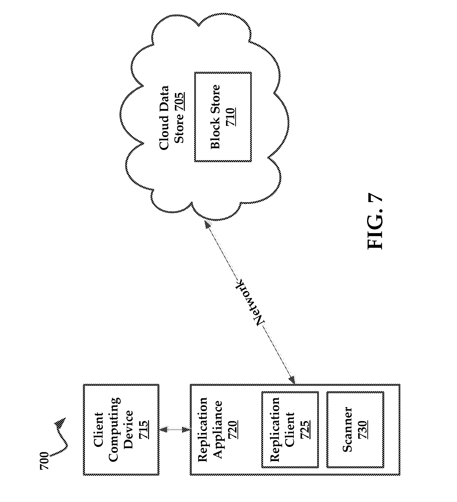
[0017] FIG. 7 is a block diagram of an exemplary architecture in which embodiments of the present technology may be practiced;
[0018] FIG. 8 illustrates an exemplary computing system that may be used to implement embodiments according to the present technology;
DESCRIPTION OF EXEMPLARY EMBODIMENTS
[0019] While this technology is susceptible of embodiment in many different forms, there is shown in the drawings and will herein be described in detail several specific embodiments with the understanding that the present disclosure is to be considered as an exemplification of the principles of the technology and is not intended to limit the technology to the embodiments illustrated.
[0020] It will be understood that like or analogous elements and/or components, referred to herein, may be identified throughout the drawings with like reference characters. It will be further understood that several of the figures are merely schematic representations of the present technology. As such, some of the components may have been distorted from their actual scale for pictorial clarity.
[0021] To be sure, each of the changes results in changes to blocks on the disk of the client computing device, which are referred to as "changed blocks". Once file system changes are deduced, the present technology can translate these file system changes to disk locations, allowing changed blocks of data to be obtained from the client computing device. The changed blocks can be replicated to a cloud data store over a network.
[0022] For context, the NTFS ondisk format is designed to be a collection of streams/files. Even the metadata about each stream, referred to as an "inode," is stored in a special stream/file called MFT (Master File Table) as series of entries with the first entry being a master file table entry (MFTEntry) for the MFT file itself. A MFTEntry can also be referred to herein as an "inode". First few MFTEntries in the MFT Table are reserved for special system files. The MFTEntry for a file contains one or more name attributes which specify a file name, parent identifier (such as an inode number or file identifier), a time entry, a sequence number, and a log sequence number--just to name a few. A time entry is a time stamp associated with a change in an inode which is recorded by the NTFS file system. A sequence number can include a numerical identifier that corresponds to a reuse of an inode. For example, if the object associated with an inode no longer exists (such as if it is deleted), the NTFS file system can update the sequence number of the inode if it is reused for a new object. The log sequence can refer to log entries for when the NTFS file system logs anticipated file system operations to objects, the actual changes, and a notation that the operation was completed. Each of these attributes provides clues as to what objects within the file system have actually changed between any two snapshots.
[0023] It is noteworthy to mention that NTFS MFTEntry contains the name of the object and also the file identifier (MFTEntry number) of the parent directory. Secondly, it is noteworthy to mention that NTFS does not allow hard links to directories. Using these two properties of NTFS, given a file identifier it is possible to do a reverse lookup of the paths of associated files and/or directories (referred to generally as "objects") including hard links by simply walking up the parent identifiers for the inodes. It will be understood that a hard link is a directory entry that associates a file name with a file on a file system. An NTFS replication client of the present technology can exploit this feature to replicate changes in file system namespace without a top down scan, which is a scan starting from a root directory.
[0024] File creation events can be determined by detecting the existence of a new MFTEntry in an MFT table and the entire path of the new file and/or a directory can be located without scanning the whole file system namespace, usually occurring in a top-down manner.
[0025] The present technology of cloud data store (or a replication appliance) uses file system metadata to allow pure inode based operations without ordering requirements. A new file and/or directory create operation can be executed by simply creating two entries with key value pairs of <dir-inode-number+entry-name, child-inode-num> and <child-inode-num, inode-attr> without requiring the corresponding entries for the full path of the new file and/or directory. Thus a full path like /foo/bar.txt can be created in reverse order (unlike traditional UNIX file systems) or any order. As long as all the create operations are applied for all the parents the file system will eventually be consistent.
[0026] It is noteworthy to mention that because cloud data store (or a replication appliance) can accept namespace operations in any order and because each MFTEntry of each NTFS file system contains all file names and parent identifiers it is possible to replicate the NTFS namespace to a cloud data store (or a replication appliance) by walking the MFT entries in file identifier order.
[0027] In some embodiments, the replication client walks through the MFT file one MFT entry at a time. For each MFT entry with a create time and/or a modified time after previous replication, the system will send the corresponding create/setattr (set attributes) operation with the parent identifier to the cloud data store (or a replication appliance). It is also possible for the system to determine if the MFT entry obtained got a new hard link (because link count increases) and a new name attribute will exist.
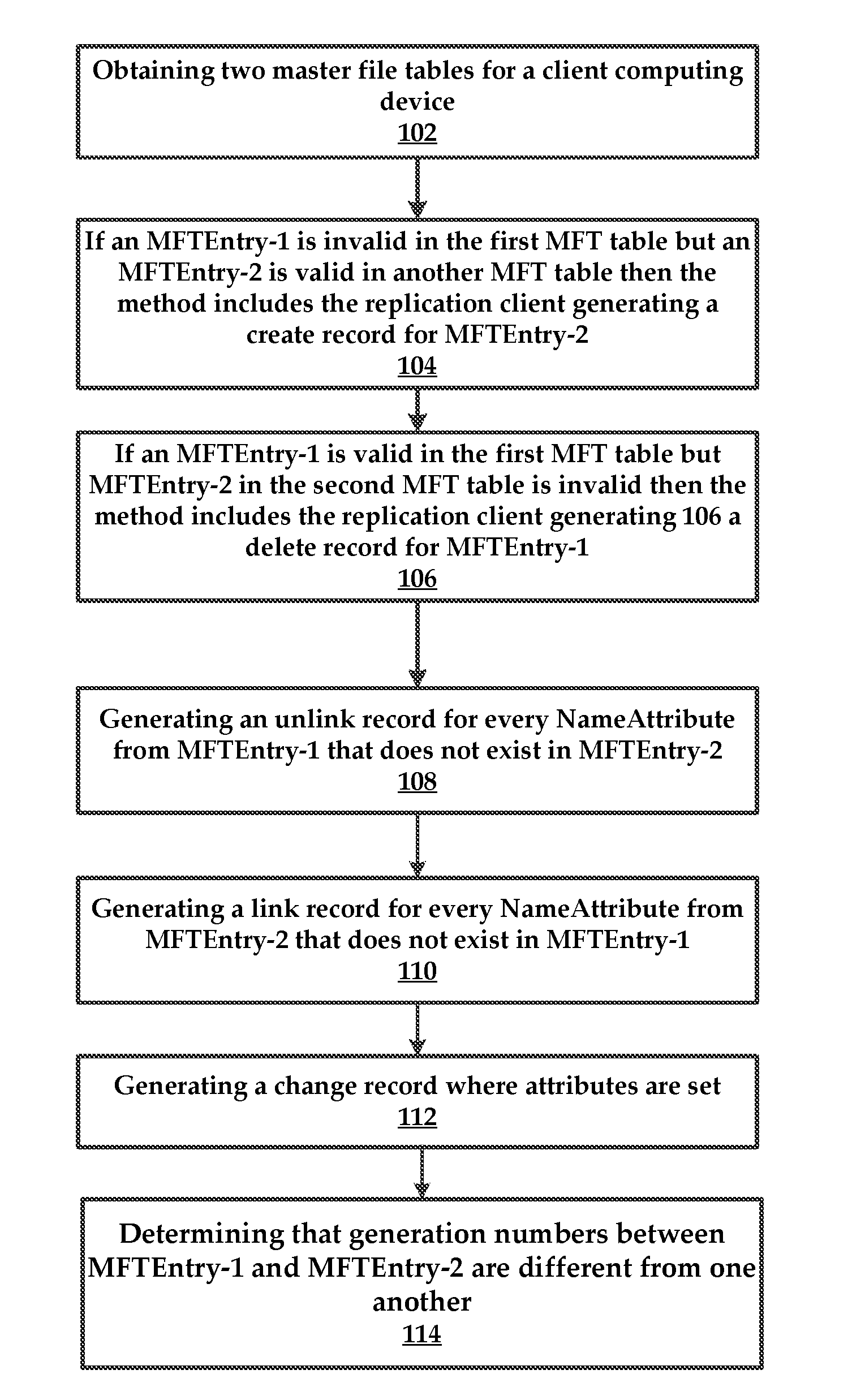
[0028] Referring now to FIG. 1, which comprises an example method for detecting changes to a file system of a client computing device. In some embodiments, the method will comprise a replication client obtaining 102 two master file tables for a client computing device. The first master file table will correspond with a first snapshot and the second master file table will correspond with a second snapshot. These snapshots are obtained at two different points in time. In some instances, the second snapshot can include a current version of a file system for the client computing device, while the first snapshot is a backup of the client computing device taken at some point in the past.
[0029] The method will include the replication client obtaining a master file table entry (MFTEntry) for a given file identifier from the first snapshot and the second snapshot. In more detail, in some embodiments this step includes obtaining the MFT tables from each of the first and second snapshots.
[0030] To be sure, the replication client reads the MFT tables together as pairs where the first MFT table is of previous version of the file system and second MFT table is the current version of the file system. For example, both MFT tables have a file identifier of "file 1" which is the first entry in each of respective MFT tables. The replication client will examine each of these pairs in sequential order such as "file 2" from the first MFT table and "file 2" from the second MFT table, and so on. Thus, the replication client need only walk the MFT tables to deduce changes. The exact details of how these changes can be detected are provided below.
[0031] An MFT table is comprised of an ordered list of entries referred to as "inodes".
[0032] In some embodiments, changes to MFT table entries can correspond to changes in a file name, a parent identifier, a time entry, sequence number, log sequence number, and any combinations thereof. These attributes are described in greater detail above.
[0033] In some embodiments, if an MFTEntry-1 is invalid in the first MFT table but an MFTEntry-2 is valid in another MFT table then the method includes the replication client generating 104 a create record for MFTEntry-2.
[0034] Similarly, if an MFTEntry-1 is valid in the first MFT table but MFTEntry-2 in the second MFT table is invalid then the method includes the replication client generating 106 a delete record for MFTEntry-1.
[0035] In some embodiments, if both MFTEntries are valid and generation numbers are same the replication client determines that both MFTEntries refer to same file. In these instances where it is determined that both MFTEntries refer to same file, the method can include the replication client inspecting the name attributes in both MFTEntries. The method can include replication client generating an unlink record 108 for every NameAttribute from MFTEntry-1 that does not exist in MFTEntry-2. Similarly, the method can include the replication client generating 110 a link record for every NameAttribute from MFTEntry-2 that does not exist in MFTEntry-1.
[0036] Similarly, in the instances where the replication client has determined that both MFTEntries refer to same same file, the method can include the replication client inspecting all other attributes in both MFTEntries. If some attributes are not the same between MFTEntry-1 and MFTEntry-2, the method can include replication client generating a 112 a set-attribute record where attributes are set.
[0037] In some embodiments, the method includes the replication client determining 114 that generation numbers between MFTEntry-1 and MFTEntry-2 are different from one another. In these instances, the method can include replication client generating a link record 110 for every NameAttribute from MFTEntry-2 illustrated in FIG. 2.
[0038] FIG. 2 illustrates an example method of data stream (e.g., file) replication, which occurs once differences are detected between MFTEntry-1 and MFTEntry-2 which indicate that an object change (e.g., file or directory) has occurred. For example, if a file name has changed the replication client can determine that a file name property has changed (e.g., a user changed the file name) or that the original file has been replaced by a new file with a different name.
[0039] For context, the method refers also to replication using SHA1 (e.g., secure hashing) maps of the client computing device to replicate changes over a network connection, as is discussed in U.S. patent application Ser. No. ______, (Attorney Docket No. PA7073US) filed on Dec. 21, 2015, entitled "Cloud Storage using Merkle Trees."
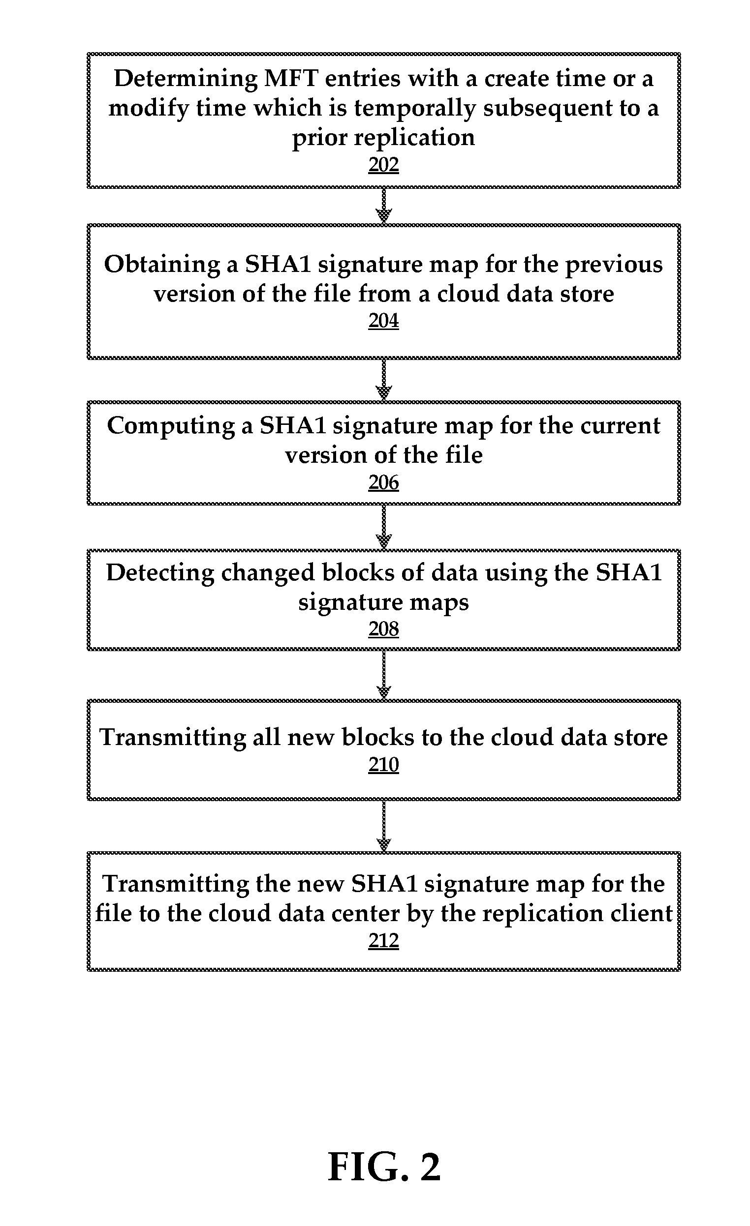
[0040] In some embodiments, the method comprises the replication client determining 202 MFT entries with a create time or a modify time which is temporally subsequent to a prior replication (e.g., snapshot).
[0041] According to some embodiments, the method includes obtaining 204 a SHA1 signature map for the previous version of the file from a cloud data store, as well as computing 206 a SHA1 signature map for the current version of the file.
[0042] The method can comprise detecting 208 changed blocks of data using the SHA1 signature maps. Once the changed blocks of data are determined the method can comprise the replication client transmitting 210 all new blocks to the cloud data store. For example, the replication client can use BULK_PUT_BLOCK application programming interface (API).
[0043] In some embodiments, the method includes transmitting 212 the new SHA1 signature map for the file to the cloud data center by the replication client. Note that the actual data blocks are replicated to the cloud data store in an operation that is separate from the process used to transmit the SHA1 signature map.
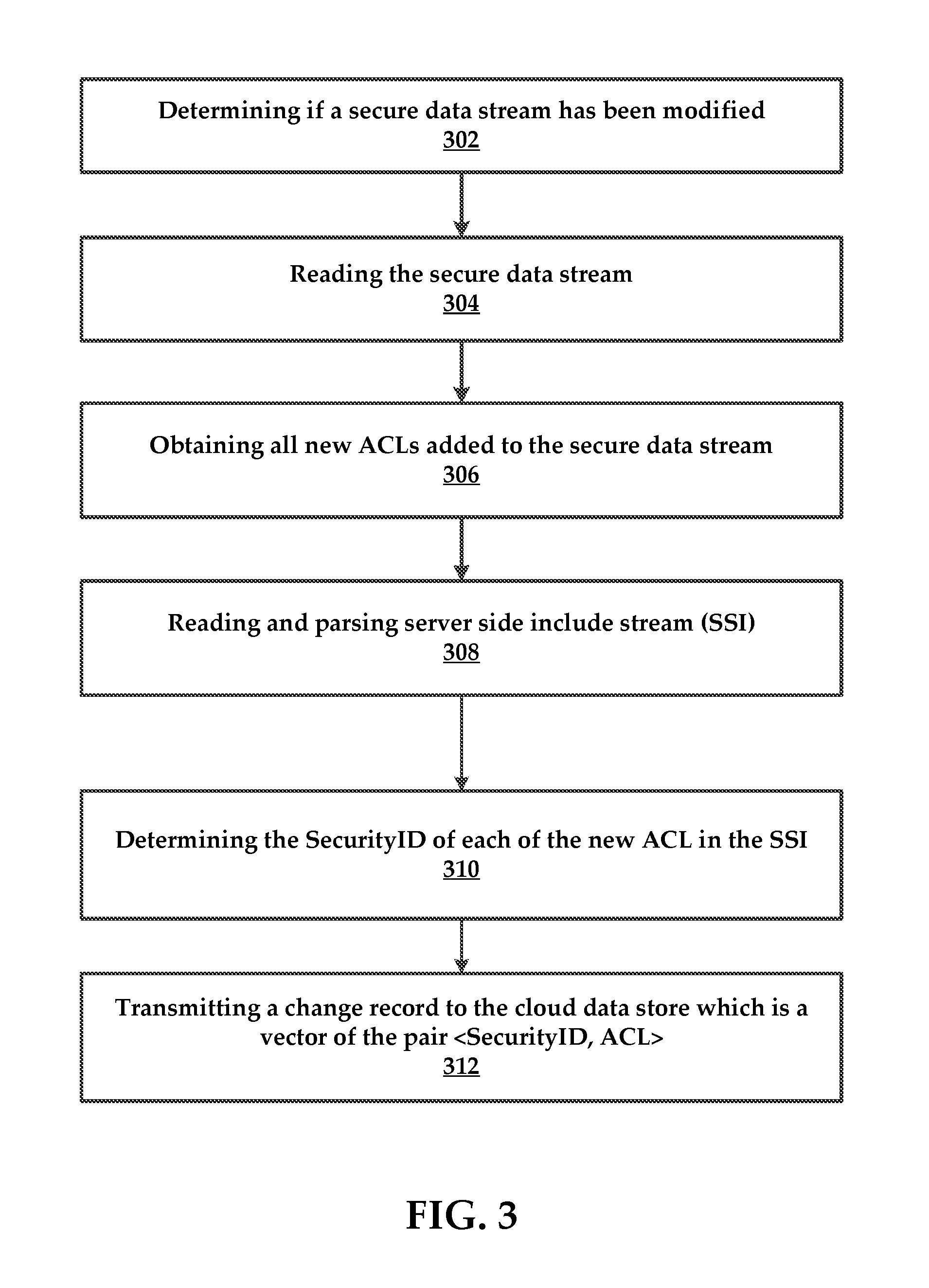
[0044] One of the reserved MFTEntry is used for access control lists (ACL) information and is called secure file in an NFTS formatted file system. All ACLs are stored in a data stream in the secure file in a sequential manner. The ACLs in the data stream are indexed by two indices stored in the secure file where one index called SDH maps `hash` of the ACL to the location of the ACL in the data stream and other index called SSI contains mapping from SecurityID security identifier to offset into the secure data where an ACL is stored. This SecurityID is stored in the STANDARD_INFORMATION of the MFTEntry of all files. Note that NTFS stores an ACL only once and every time a new file is created with an ACL, if the ACL is already stored in the secure data stream then the new MFTEntry gets the same SecurityID. If a new ACL which does not already exists in the data stream is created by the system, only then it is stored and it gets appended to the data stream and is assigned a new SecurityID.
[0045] In some embodiments, the replication client will detect change in the size and or update time of the secure file and replicate the changes. In some embodiments, the replication client will utilize metadata that will maintain the same SecurityID as in the source NTFS volume. In some embodiments, the metadata is provided with a new key-value pair as <SecurityID, ACL> and the SecurityID can be stored in the inode attributes just the way NTFS stores it in MFTEntry.
[0046] An example ACL replication process is illustrated in FIG. 3. The method can comprise a step of determining 302 if a $Secure data stream has been modified. If so, the method comprises reading 304 the $Secure data stream and obtaining 306 all new ACLs added to the $Secure data stream.
[0047] Next, the method can comprise reading and parsing 308 $SSI, as well as determining 310 the SecurityID of each of the new ACL in the SSI.
[0048] The method includes transmitting 312 a change record to the cloud data store which is a vector of the pair <SecurityID, ACL>.
[0049] In some embodiments, the present technology can be applied to systems and methods that utilize snapshots and differential files for replication of the client computing device.
[0050] FIG. 4 illustrates an example method for replicating metadata changes for a client computing device.
[0051] In some embodiments, the method includes a scanner of a replication client performing 402 a top-down walk of an entire file system tree (taken from a snapshot) and comparing 404 the file system tree with a previous snapshot to determine namespace changes. The method includes generating 406 a metadata log with the namespace changes. The method comprises the scanner comparing 408 the file modified time for inode pairs to determine list of changed files. Next, the method includes evaluating 410 the file system metadata and namespace (directory hierarchy) in two locations on the appliance. The method further comprises generating 412 a shell NTFS volume image that has all file system metadata (ACLs and even file block map) and namespace (directory hierarchy). No file data is obtained in this step, in some embodiments.
[0052] In one embodiment, the method comprises obtaining differential metadata which stores only the file system name space (directory hierarchy).
[0053] In some embodiments, the method includes the scanner transferring 414 the metadata log to the replication appliance where it is applied to the NTFS shell volume. According to some embodiments, the method includes performing 416 another top-down walk of NTFS shell volume (via fuse mount for example) and comparing 418 with a previous version of differential metadata. In some embodiments the method includes generating 420 new differential metadata based on the comparison.
[0054] For context, the method refers to U.S. patent application Ser. No. 14/864,850, filed Sep. 24, 2015, entitled "Distributed and Deduplicating Data Storage System and Methods of Use."
[0055] In some embodiments, no metadata log is required or applied to backup server. The metadata and namespace changes are replicated by copying all the disk blocks of the file system that are used to store the file system metadata and namespace information. For context, most file systems support cloning of just the file system namespace and metadata without the file data. The replication client can be configured to use existing file system cloning tools (like ntfsclone for NTFS) to replicate full file system namespace and metadata from the client computing device to the replication appliance. By using NTFSclone a NTFS shell volume is generated and saved on the replication appliance, thus keeping the ondisk format the same.
[0056] Optimized Namespace Change Tracking
[0057] As mentioned above, most file systems allocate inodes for each object (file/directory) in a simple indexed table MFT giving each inode a number, referred to as a file number. On deletion of an inode the index number is free and can be used for new object (file/directory) later. Using file system tools it is possible to walk through all the inodes starting from index zero to max allocated. Instead of performing a full directory walk of two versions of the file system to compare metadata of two versions of files (like modified time or other attributes) to determine if a file has changed, the replication client can directly compare two versions of the file inodes. Since this solution directly reads the inodes one by one the replication client can avoid having to read the directories, which is required in top down namespace walk.
[0058] The replication client uses one or more of the following properties/attributes of a NTFS ondisk inode (called MFT entry). In one embodiment, NTFS stores a generation number in the inode that makes it possible to detect reuse of inode for new object (file/directory). In another embodiment, NTFS stores object (file/directory) name in the inode itself which makes it possible to detect "rename" operations on inodes. NTFS also stores parent file identifiers of an object (file/directory) in the inode itself which makes it possible to detect "move" operations on inodes. In NTFS all the inodes are stored as a simple ondisk array in a special file called MFT Table. Two versions of MFT table are compared for each MFT record and change log is generated as follows:
[0059] FIG. 5 an example method that is executed by the replication client using the rules set forth above. If the two MFT records are same the replication client does nothing. Again, the comparison includes comparing pairs of MFT entries to one another in a sequential manner (e.g., following inode file identifiers in numerical order from top to bottom).
[0060] If the first MFT entry is unused and used in second MFT entry then enter a create entry 502 into a log record. If the first MFT entry is unused in a new MFT table and unused in an older MFT table then create 504 a log entry that reflects a delete operation.
[0061] If the generation number is different, a log object (file/dir) is created 506 for the new first MFT entry and the old first MFT entry is deleted.
[0062] If the MFT entry in both versions is identical except for a modified time then a log entry is created 508 that indicates that the file/directory has changed. In some embodiments, the method ignores directory changes and log entries are created only for files. This is due to directories being replicated in other processes, such as when metadata is replicated.
[0063] If the MFT record has (same generation number) a different name (or additional name) then a log entry is created 510 that is indicative of a rename.
[0064] If the MFT record has (same generation number) a different parent identifier then a log entry is created 512 that indicate a move.
[0065] In some embodiments the backup server can require that change records are addressed by a full file path and not only by inode numbers. However, the file change log address files using file identifiers. The backup-sender converts the file identifier to a namespace path by opening the file by using file identifier and then performing a getFileInformation operation on the handle to get full path of the file.
[0066] A change log for this process can be converted or transformed into a "refined log" as follows. For every directory rename or move record, the replication client is configured to perform a full tree walk of a directory and add a "create file" record for all the children files within the directory. If one of the child files already had a "modified file" record, that record is replaced with "create file" record. For every file rename or move record the replication client can add a "create file" record for that file and delete any "modified file" record for that file.
[0067] A refined log contains only "file data change" records which are either "incremental change" (modify) or "full backup" (create). This refined log is used by the replication client to send FCRs to the appliance.
[0068] Following is an example list of pseudo-code to generate the FILE_CHANGE_LOG and DIR_CHANGE_LOG:
[0069] Example code for generating the refined version of the FILE_CHANGE_LOG generated is provided below. The refine log generation is done by a separate program whose input is the DIR_CHANGE_LOG and FILE_CHANGE_LOG and output is REFINED_FILE_CHANGE_LOG. In one embodiment, the code specifies:
TABLE-US-00001 HashMap FILE_LOG = read(FILE_CHANGE_LOG) List DIR_LOG = read(DIR_CHANGE_LOG) for dir in DIR_LOG do //Walk the directory pointed by record for file in dir do //Remove any record that exist in FILE_LOG for this file FILE_LOG.remove(file) //Add file as create record in FILE_LOG FILE_LOG.add(file, "Created") done done Flush(FILE_LOG)
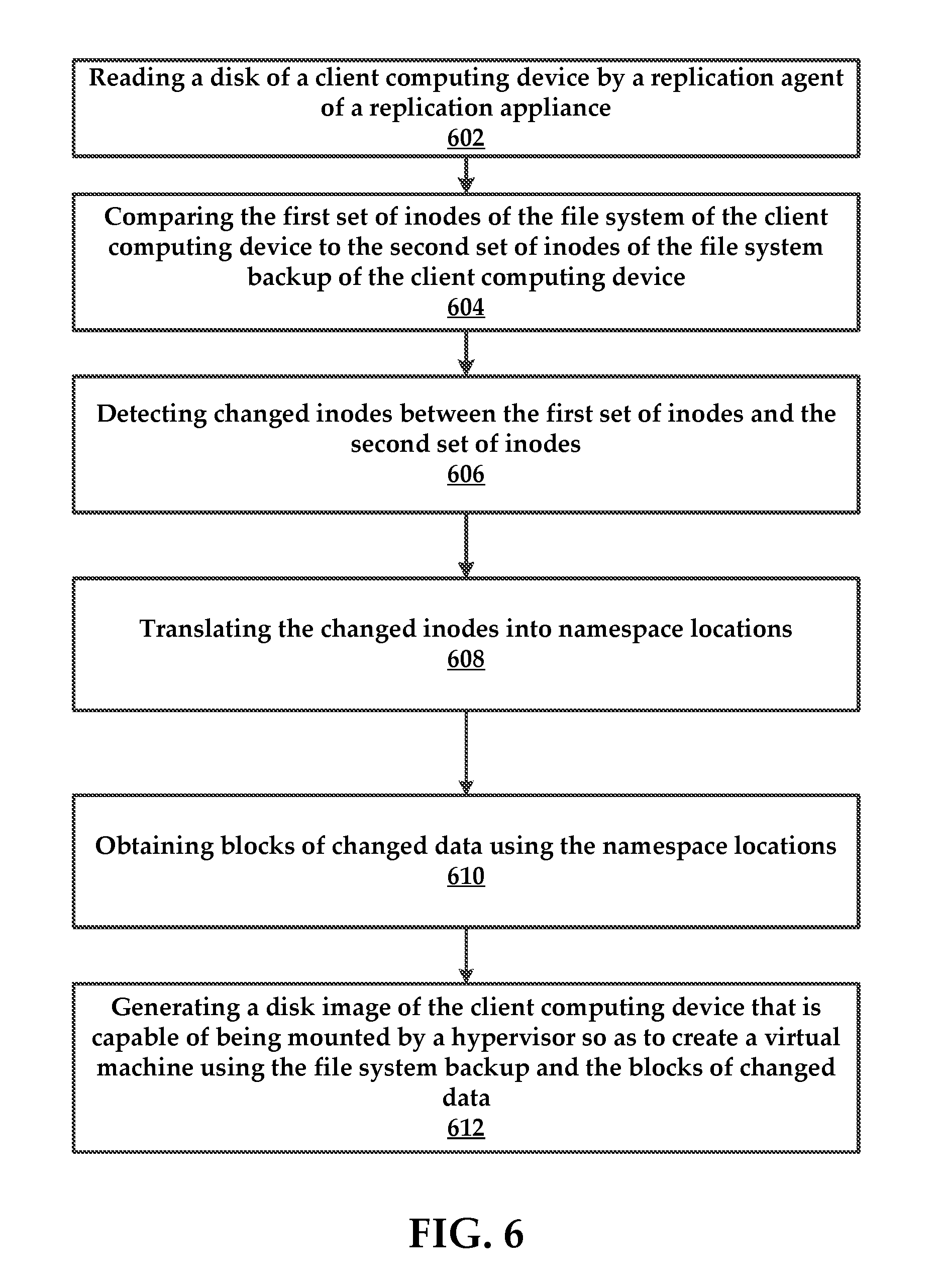
[0070] FIG. 6 illustrates an example method for determining changes to a file system and using the changes to create a disk image that can be booted by a hypervisor (for example) to instantiate a virtual machine. The disk image can also be booted by a physical device (e.g., bare metal hardware).
[0071] In some embodiments, the method comprises reading 602 a disk of a client computing device by a replication agent of a replication appliance. In one example, reading comprises walking a first set of inodes of a file system of the client computing device at a first point in time. Again, these inodes belong to an MFT table for the client computing device. A second set of inodes of a file system backup are also read for the client computing device.
[0072] Next, the method includes comparing 604 the first set of inodes of the file system of the client computing device to the second set of inodes of the file system backup of the client computing device.
[0073] In some embodiments, the method comprises detecting 606 changed inodes between the first set of inodes and the second set of inodes and translating 608 the changed inodes into namespace locations. Again, this can be accomplished by using file identifiers, which point to locations on the disk where objects within the file system are located.
[0074] Next, the method can comprise obtaining 610 blocks of changed data using the namespace locations.
[0075] The method can also include generating 612 a disk image of the client computing device that is capable of being mounted by a hypervisor so as to create a virtual machine using the file system backup and the blocks of changed data.
[0076] Referring now to the drawings, and more particularly, to FIG. 7, which includes a schematic diagram of an exemplary architecture 700 for practicing the present invention. Architecture 700 may include a cloud data store 705, which can comprise a block store 710 for storing blocks of data for a client computing device 715.
[0077] In some embodiments the client computing device 715 is coupled to a replication appliance 720 that employs a replication client 725 (NTFS based) and a scanner 730. The replication client 725 and scanner 730 are described in many of the embodiments above.
[0078] A cloud-based computing environment. In general, a cloud-based computing environment is a resource that typically combines the computational power of a large model of processors and/or that combines the storage capacity of a large model of computer memories or storage devices. For example, systems that provide a cloud resource may be utilized exclusively by their owners, such as Google.TM. or Yahoo!.TM.; or such systems may be accessible to outside users who deploy applications within the computing infrastructure to obtain the benefit of large computational or storage resources.
[0079] The cloud may be formed, for example, by a network of servers, with each server (or at least a plurality thereof) providing processor and/or storage resources. These servers may manage workloads provided by multiple users (e.g., cloud resource consumers or other users). Typically, each user places workload demands upon the cloud that vary in real-time, sometimes dramatically. The nature and extent of these variations typically depend on the type of business associated with the user.
[0080] In some instances the block store 710 may include a deduplicating block store that stores blocks of data for one or more objects, such as a file, a group of files, or an entire disk. Additionally the block store 710 may comprise Merkle trees that include hash-type representations of objects within the deduplicating block store. That is, for each object (or group of blocks), a Merkle tree exists that represents the blocks of the object.
[0081] In other embodiments, the block store 705 can implement storage for differential backups instead of Merkle trees.
[0082] According to some embodiments, the deduplicating block store may include immutable object addressable block storage. The deduplicating block store may form an underlying storage foundation that allows for the storing of blocks of objects. The identifiers of the blocks are a unique representation of the block, generated for example by using a uniform hash function.
[0083] FIG. 8 illustrates an exemplary computing system 800 that may be used to implement an embodiment of the present technology. The computing system 800 of FIG. 8 includes one or more processors 810 and memory 820. Main memory 820 stores, in part, instructions and data for execution by processor 810. Main memory 820 can store the executable code when the system 800 is in operation. The system 800 of FIG. 8 may further include a mass storage device 830, portable storage medium drive(s) 840, output devices 850, user input devices 860, a graphics display 870, and other peripheral devices 880. The system 800 may also comprise network storage 845.
[0084] The components shown in FIG. 8 are depicted as being connected via a single bus 890. The components may be connected through one or more data transport means. Processor unit 810 and main memory 820 may be connected via a local microprocessor bus, and the mass storage device 830, peripheral device(s) 880, portable storage device 840, and graphics display 870 may be connected via one or more input/output (I/O) buses.
[0085] Mass storage device 830, which may be implemented with a magnetic disk drive or an optical disk drive, is a non-volatile storage device for storing data and instructions for use by processor unit 810. Mass storage device 830 can store the system software for implementing embodiments of the present technology for purposes of loading that software into main memory 820.
[0086] Portable storage device 840 operates in conjunction with a portable non-volatile storage medium, such as a floppy disk, compact disk or digital video disc, to input and output data and code to and from the computing system 800 of FIG. 8. The system software for implementing embodiments of the present technology may be stored on such a portable medium and input to the computing system 800 via the portable storage device 840.
[0087] Input devices 860 provide a portion of a user interface. Input devices 860 may include an alphanumeric keypad, such as a keyboard, for inputting alphanumeric and other information, or a pointing device, such as a mouse, a trackball, stylus, or cursor direction keys. Additionally, the system 800 as shown in FIG. 8 includes output devices 850. Suitable output devices include speakers, printers, network interfaces, and monitors.
[0088] Graphics display 870 may include a liquid crystal display (LCD) or other suitable display device. Graphics display 870 receives textual and graphical information, and processes the information for output to the display device.
[0089] Peripherals 880 may include any type of computer support device to add additional functionality to the computing system. Peripheral device(s) 880 may include a modem or a router.
[0090] The components contained in the computing system 800 of FIG. 8 are those typically found in computing systems that may be suitable for use with embodiments of the present technology and are intended to represent a broad category of such computer components that are well known in the art. Thus, the computing system 800 can be a personal computer, hand held computing system, telephone, mobile computing system, workstation, server, minicomputer, mainframe computer, or any other computing system. The computer can also include different bus configurations, networked platforms, multi-processor platforms, etc. Various operating systems can be used including UNIX, Linux, Windows, Macintosh OS, Palm OS, and other suitable operating systems.
[0091] As used herein, the term "module" may also refer to any of an application-specific integrated circuit ("ASIC"), an electronic circuit, a processor (shared, dedicated, or group) that executes one or more software or firmware programs, a combinational logic circuit, and/or other suitable components that provide the described functionality. In other embodiments, individual modules may include separately configured web servers.
[0092] Some of the above-described functions may be composed of instructions that are stored on storage media (e.g., computer-readable medium). The instructions may be retrieved and executed by the processor. Some examples of storage media are memory devices, tapes, disks, and the like. The instructions are operational when executed by the processor to direct the processor to operate in accord with the technology. Those skilled in the art are familiar with instructions, processor(s), and storage media.
[0093] It is noteworthy that any hardware platform suitable for performing the processing described herein is suitable for use with the technology. The terms "computer-readable storage medium" and "computer-readable storage media" as used herein refer to any medium or media that participate in providing instructions to a CPU for execution. Such media can take many forms, including, but not limited to, non-volatile media, volatile media and transmission media. Non-volatile media include, for example, optical or magnetic disks, such as a fixed disk. Volatile media include dynamic memory, such as system RAM. Transmission media include coaxial cables, copper wire and fiber optics, among others, including the wires that comprise one embodiment of a bus. Transmission media can also take the form of acoustic or light waves, such as those generated during radio frequency (RF) and infrared (IR) data communications. Common forms of computer-readable media include, for example, a floppy disk, a flexible disk, a hard disk, magnetic tape, any other magnetic medium, a CD-ROM disk, digital video disk (DVD), any other optical medium, any other physical medium with patterns of marks or holes, a RAM, a PROM, an EPROM, an EEPROM, a FLASHEPROM, any other memory chip or data exchange adapter, a carrier wave, or any other medium from which a computer can read.
[0094] Various forms of computer-readable media may be involved in carrying one or more sequences of one or more instructions to a CPU for execution. A bus carries the data to system RAM, from which a CPU retrieves and executes the instructions. The instructions received by system RAM can optionally be stored on a fixed disk either before or after execution by a CPU.
[0095] Computer program code for carrying out operations for aspects of the present invention may be written in any combination of one or more programming languages, including an object oriented programming language such as Java, Smalltalk, C++ or the like and conventional procedural programming languages, such as the "C" programming language or similar programming languages. The program code may execute entirely on the user's computer, partly on the user's computer, as a stand-alone software package, partly on the user's computer and partly on a remote computer or entirely on the remote computer or server. In the latter scenario, the remote computer may be connected to the user's computer through any type of network, including a local area network (LAN) or a wide area network (WAN), or the connection may be made to an external computer (for example, through the Internet using an Internet Service Provider).
[0096] The corresponding structures, materials, acts, and equivalents of all means or step plus function elements in the claims below are intended to include any structure, material, or act for performing the function in combination with other claimed elements as specifically claimed. The description of the present invention has been presented for purposes of illustration and description, but is not intended to be exhaustive or limited to the invention in the form disclosed. Many modifications and variations will be apparent to those of ordinary skill in the art without departing from the scope and spirit of the invention. Exemplary embodiments were chosen and described in order to best explain the principles of the present technology and its practical application, and to enable others of ordinary skill in the art to understand the invention for various embodiments with various modifications as are suited to the particular use contemplated.
[0097] Aspects of the present invention are described above with reference to flowchart illustrations and/or block diagrams of methods, apparatus (systems) and computer program products according to embodiments of the invention. It will be understood that each block of the flowchart illustrations and/or block diagrams, and combinations of blocks in the flowchart illustrations and/or block diagrams, can be implemented by computer program instructions. These computer program instructions may be provided to a processor of a general purpose computer, special purpose computer, or other programmable data processing apparatus to produce a machine, such that the instructions, which execute via the processor of the computer or other programmable data processing apparatus, create means for implementing the functions/acts specified in the flowchart and/or block diagram block or blocks.
[0098] These computer program instructions may also be stored in a computer readable medium that can direct a computer, other programmable data processing apparatus, or other devices to function in a particular manner, such that the instructions stored in the computer readable medium produce an article of manufacture including instructions which implement the function/act specified in the flowchart and/or block diagram block or blocks.
[0099] The computer program instructions may also be loaded onto a computer, other programmable data processing apparatus, or other devices to cause a series of operational steps to be performed on the computer, other programmable apparatus or other devices to produce a computer implemented process such that the instructions which execute on the computer or other programmable apparatus provide processes for implementing the functions/acts specified in the flowchart and/or block diagram block or blocks.
[0100] The flowchart and block diagrams in the Figures illustrate the architecture, functionality, and operation of possible implementations of systems, methods and computer program products according to various embodiments of the present invention. In this regard, each block in the flowchart or block diagrams may represent a module, segment, or portion of code, which comprises one or more executable instructions for implementing the specified logical function(s). It should also be noted that, in some alternative implementations, the functions noted in the block may occur out of the order noted in the figures. For example, two blocks shown in succession may, in fact, be executed substantially concurrently, or the blocks may sometimes be executed in the reverse order, depending upon the functionality involved. It will also be noted that each block of the block diagrams and/or flowchart illustration, and combinations of blocks in the block diagrams and/or flowchart illustration, can be implemented by special purpose hardware-based systems that perform the specified functions or acts, or combinations of special purpose hardware and computer instructions.
[0101] While various embodiments have been described above, it should be understood that they have been presented by way of example only, and not limitation. The descriptions are not intended to limit the scope of the technology to the particular forms set forth herein. Thus, the breadth and scope of a preferred embodiment should not be limited by any of the above-described exemplary embodiments. It should be understood that the above description is illustrative and not restrictive. To the contrary, the present descriptions are intended to cover such alternatives, modifications, and equivalents as may be included within the spirit and scope of the technology as defined by the appended claims and otherwise appreciated by one of ordinary skill in the art. The scope of the technology should, therefore, be determined not with reference to the above description, but instead should be determined with reference to the appended claims along with their full scope of equivalents.
* * * * *
D00000
D00001
D00002
D00003
D00004
D00005
D00006
D00007
D00008
XML
uspto.report is an independent third-party trademark research tool that is not affiliated, endorsed, or sponsored by the United States Patent and Trademark Office (USPTO) or any other governmental organization. The information provided by uspto.report is based on publicly available data at the time of writing and is intended for informational purposes only.
While we strive to provide accurate and up-to-date information, we do not guarantee the accuracy, completeness, reliability, or suitability of the information displayed on this site. The use of this site is at your own risk. Any reliance you place on such information is therefore strictly at your own risk.
All official trademark data, including owner information, should be verified by visiting the official USPTO website at www.uspto.gov. This site is not intended to replace professional legal advice and should not be used as a substitute for consulting with a legal professional who is knowledgeable about trademark law.