Optical Imaging Lens Assembly
WENREN; Jianke
U.S. patent application number 16/211696 was filed with the patent office on 2019-04-11 for optical imaging lens assembly. The applicant listed for this patent is Zhejiang Sunny Optical Co., Ltd. Invention is credited to Jianke WENREN.
| Application Number | 20190107690 16/211696 |
| Document ID | / |
| Family ID | 64949719 |
| Filed Date | 2019-04-11 |


View All Diagrams
| United States Patent Application | 20190107690 |
| Kind Code | A1 |
| WENREN; Jianke | April 11, 2019 |
OPTICAL IMAGING LENS ASSEMBLY
Abstract
The present disclosure discloses an optical imaging lens assembly. The optical imaging lens assembly includes a first lens, a second lens, a third lens, a fourth lens, a fifth lens, a sixth lens, a seventh lens, and an eighth lens, sequentially arranged from an object side to an image side along an optical axis. The first lens, the second lens, the fifth lens, the seventh lens, and the eighth lens may respectively have a positive focal power or a negative focal power. A combined focal power of the third lens and the fourth lens is a positive focal power. The sixth lens may have a positive focal power. An effective focal length f of the optical imaging lens assembly and a combined focal length f34 of the third lens and the fourth lens satisfy: 0.5.ltoreq.f/f34<1.0.
| Inventors: | WENREN; Jianke; (Ningbo, CN) | ||||||||||
| Applicant: |
|
||||||||||
|---|---|---|---|---|---|---|---|---|---|---|---|
| Family ID: | 64949719 | ||||||||||
| Appl. No.: | 16/211696 | ||||||||||
| Filed: | December 6, 2018 |
Related U.S. Patent Documents
| Application Number | Filing Date | Patent Number | ||
|---|---|---|---|---|
| PCT/CN2018/072776 | Jan 16, 2018 | |||
| 16211696 | ||||
| Current U.S. Class: | 1/1 |
| Current CPC Class: | G02B 13/00 20130101; G02B 13/0045 20130101; G02B 26/123 20130101; G02B 13/18 20130101; G02B 13/0005 20130101; G02B 9/64 20130101 |
| International Class: | G02B 13/00 20060101 G02B013/00; G02B 13/18 20060101 G02B013/18; G02B 26/12 20060101 G02B026/12 |
Foreign Application Data
| Date | Code | Application Number |
|---|---|---|
| Jul 5, 2017 | CN | 201710542434.8 |
| Jul 5, 2017 | CN | 201720806420.8 |
Claims
1. An optical imaging lens assembly, comprising a first lens, a second lens, a third lens, a fourth lens, a fifth lens, a sixth lens, a seventh lens, and an eighth lens, sequentially arranged from an object side to an image side along an optical axis, wherein each of the first lens, the second lens, the fifth lens, the seventh lens, and the eighth lens has a positive focal power or a negative focal power; a combined focal power of the third lens and the fourth lens is a positive focal power; the sixth lens has a positive focal power; and an effective focal length f of the optical imaging lens assembly and a combined focal length f34 of the third lens and the fourth lens satisfy: 0.5.ltoreq.f/f34<1.0.
2. The optical imaging lens assembly according to claim 1, wherein the third lens has a positive focal power and the fourth lens has a negative focal power.
3. The optical imaging lens assembly according to claim 2, wherein a radius R7 of curvature of an object-side surface of the fourth lens and a radius R8 of curvature of an image-side surface of the fourth lens satisfy: 0<(R7-R8)/(R7+R8)<1.0.
4. The optical imaging lens assembly according to claim I, wherein an optical-axis distance TTL from an object-side surface of the first lens to an image plane of the optical imaging lens assembly and a half of a diagonal length ImgH of an effective pixel area on the image plane of the optical imaging lens assembly satisfy: TTL/ImgH.ltoreq.1.7.
5. The optical imaging lens assembly according to claim 1, wherein the effective focal length f of the optical imaging lens assembly and a combined focal length f12 of the first lens and the second lens satisfy: 0<f/f12<0.5.
6. The optical imaging lens assembly according to claim 1, wherein the effective focal length f of the optical imaging lens assembly and an effective focal length f1 of the first lens satisfy: |f/f1|.ltoreq.0.1.
7. The optical imaging lens assembly according to claim 1, wherein a radius R3 of curvature of an object-side surface of the second lens and a radius R4 of curvature of an image-side surface of the second lens satisfy: 0.6<R3/R4<1.2.
8. The optical imaging lens assembly according to claim 1, wherein a center thickness CT2 of the second lens on the optical axis and a center thickness CT3 of the third lens on the optical axis satisfy: 0.5<CT2/CT3<0.8.
9. The optical imaging lens assembly according to claim 1, wherein the effective focal length f of the optical imaging lens assembly and an effective focal length f5 of the fifth lens satisfy: |f/f5|.ltoreq.10.1.
10. The optical imaging lens assembly according to claim I, wherein a center thickness CT6 of the sixth lens on the optical axis and a center thickness CT7 of the seventh lens on the optical axis satisfy: 0.7<CT6/CT7<1.2.
11. The optical imaging lens assembly according to claim 1, wherein the effective focal length f of the optical imaging lens assembly and a combined focal length f78 of the seventh lens and the eighth lens satisfy: -0.5<f/f78<0.
12. The optical imaging lens assembly according to claim 1, wherein the effective focal length f of the optical imaging lens assembly and an entrance pupil diameter EPD of the optical imaging lens assembly satisfy: f/EPD.ltoreq.1.8.
13. An optical imaging lens assembly, comprising a first lens, a second lens, a third lens, a fourth lens, a fifth lens, a sixth lens, a seventh lens, and an. eighth lens, sequentially arranged from an object side to an image side along an optical axis. wherein each of the first lens, the second lens, and the fifth lens has a positive focal power or a negative focal power; each of the third lens and the sixth lens has a positive focal power; the fourth lens has a negative focal power; a combined focal power of the seventh lens and the eighth lens is a negative focal power; and an effective focal length f of the optical imaging lens assembly and a combined focal length f78 of the seventh lens and the eighth lens satisfy: -0.5<f/f78<0.
14. The optical imaging lens assembly according to claim 13, wherein at least one of the seventh lens and. the eighth lens has a negative focal power.
15. The optical imaging lens assembly according to claim 13, wherein a combined focal power of the third lens and the fourth. lens is a positive focal power.
16. The optical imaging lens assembly according to claim 13, wherein an optical-axis distance iii from an object-side surface of the first lens to an image plane of the optical imaging lens assembly and a half of a diagonal length ImgH of an effective pixel area on the image plane of the optical imaging lens assembly satisfy: TTL/ImgH.ltoreq.1.7.
17. The optical imaging lens assembly according to claim 16, wherein the effective focal length f of the optical imaging lens assembly and an entrance pupil diameter EPD of the optical imaging lens assembly satisfy: f/EPD.ltoreq.1.8.
18. The optical imaging lens assembly according to claim 17, wherein the effective focal length f of the optical imaging lens assembly and an effective focal length f6 of the sixth lens satisfy: 0<f/f6<0.5.
19. The optical imaging lens assembly according to claim 17, wherein the effective focal length f of the optical imaging lens assembly and an effective focal length f5 of the fifth lens satisfy: |f/f5|0.1.
20. The optical imaging lens assembly according to claim 17, wherein the effective focal length f of the optical imaging lens assembly and a radius R11 of curvature of an object-side surface of the sixth lens satisfy: 5<f/R11<1.0.
21. The optical imaging lens assembly according to claim 17, wherein a center thickness CT6 of the sixth lens on the optical axis and a center thickness CT7 of the seventh lens on the optical axis satisfy: 0.7<CT6/CT7<1.2.
22. The optical imaging lens assembly according to claim 17, wherein a radius R13 of curvature of an object-side surface of the seventh lens and a radius R14 of curvature of an image-side surface of the seventh lens satisfy: |(R13-R14)/(R13+R14)|.ltoreq.0.5.
23. The optical .imaging lens assembly according to claim 17, wherein a radius R15 of curvature of an object-side surface of the eighth lens and a radius R16 of curvature of an image---side surface of the eighth lens satisfy: 1.ltoreq.R15/R16<1.5.
Description
CROSS-REFERENCE TO RELATED APPLICATIONS
[0001] This application is a continuation of International Application No. PCT/CN2018/072776, filed on Jan. 16, 2018, which claims the priorities and rights from Chinese Patent Application No. 201710542434.8 and Chinese Patent Application No. 201720806420.8 filed with the China National Intellectual Property Administration (CNIPA) on Jul. 5, 2017. All of the aforementioned applications are hereby incorporated by reference in their entireties.
TECHNICAL FIELD
[0002] The present disclosure relates to an optical imaging lens assembly, and more specifically to an optical imaging lens assembly including eight lenses.
BACKGROUND
[0003] As the science and technology develop, the semiconductor technology is continuously improved. Accordingly, high-quality imaging lens assemblies have gradually become the mainstream trend in the market. With their continuous developments, the portable electronic products such as mobile phones and tablet computers have become thinner and smaller. In particular, a 360-degree around view application currently having a growing market has brought forward higher requirements on performances of the optical imaging lens assembly such as miniaturization, lightweight, and image quality.
[0004] In order to satisfy the requirements of miniaturization and high quality, with the continuous development of the portable electronic products such as smart phones, higher requirements on the imaging lens assembly have been brought forward, especially in situations such as insufficient lights (e.g., cloudy and rainy days, at dusk, night view, and a starry sky). Accordingly, an F-number of 2.0 or above has been unable to meet higher-order imaging requirements. In order to acquire more entrance lights, the imaging lens assembly having a smaller F-number is required. In order to satisfy a higher image quality to provide a better imaging experience for a user, more lenses are needed, and thus the lens assembly having a plurality of lenses becomes a mainstream product in the high-end market.
[0005] Therefore, the present disclosure proposes an optical imaging lens assembly having optical characteristics such as multi-piece, ultra-thin, large aperture, miniaturization, and good image quality and applicable to the portable electronic products.
SUMMARY
[0006] The technical solution provided by the present disclosure at least partially solves the technical problem described above.
[0007] According to an aspect, the present disclosure provides an optical imaging lens assembly. The optical imaging lens assembly includes a first lens, a second lens, a third lens, a fourth lens, a fifth lens, a sixth lens, a seventh lens, and an eighth lens, sequentially arranged from an object side to an image side along an optical axis. Each of the first lens, the second lens, the fifth lens, the seventh lens, and the eighth lens may have a positive focal power or a negative focal power. A combined focal power of the third lens and the fourth lens is a positive focal power. The sixth lens may have a positive focal power. An effective focal length f of the optical imaging lens assembly and a combined focal length f34 of the third lens and the fourth lens may satisfy: 0.5.ltoreq.f/f34<1.0, for example, 0.53.ltoreq.f/f34<0.74.
[0008] According to another aspect, the present disclosure further provides an optical imaging lens assembly. The optical imaging lens assembly includes a first lens, a second lens, a third lens, a fourth lens, a fifth lens, a sixth lens, a seventh lens, and an eighth lens, sequentially arranged from an object side to an image side along an optical axis. Each of the first lens, the second lens, and the fifth lens may have a positive focal power or a negative focal power. Each of the third lens and the sixth lens may have a positive focal power. The fourth lens may have a negative focal power. A combined focal power of the seventh lens and the eighth lens is a negative focal power. An effective focal length f of the optical imaging lens assembly and a combined focal length f78 of the seventh lens and the eighth lens satisfy: -0.5<f/f78<0.
[0009] In an implementation, a combined focal power of the third lens and the fourth lens is a positive focal power.
[0010] In an implementation, the third lens may have a positive focal power, and the fourth lens may have a negative focal power.
[0011] In an implementation, the combined focal power of the seventh lens and the eighth lens is a negative focal power.
[0012] In an implementation, at least one of the seventh lens and the eighth lens has a negative focal power.
[0013] In an implementation, the effective focal length f of the optical imaging lens assembly and a combined focal length f34 of the third lens and the fourth lens may satisfy: 0.5.ltoreq.f/f34<1.0.
[0014] In an implementation, an optical-axis distance TTL from an object-side surface of the first lens to an image plane of the optical imaging lens assembly and a half of a diagonal length ImgH of an effective pixel area on the image plane of the optical imaging lens assembly may satisfy: TTL/ImgH.ltoreq.1.7.
[0015] In an implementation, the effective focal length f of the optical imaging lens assembly and an effective focal length f6 of the sixth lens may satisfy: 0<f/f6<0.5, for example, 0.31.ltoreq.f/f6.ltoreq.0.41.
[0016] In an implementation, the effective focal length f of the optical imaging lens assembly and a combined focal length f12 of the first lens and the second lens may satisfy: 021 f/f12<0.5, for example, 0.05.ltoreq.f/f12.ltoreq.0.23.
[0017] In an implementation, the effective focal length f of the optical imaging lens assembly and an effective focal length f1 of the first lens may satisfy: |f/f1|.ltoreq.0.1, for example, |f/f1|.ltoreq.0.05.
[0018] In an implementation, a radius R3 of curvature of an object-side surface of the second lens and a radius R4 of curvature of an image-side surface of the second lens may satisfy: 0.6<R3/R4<1.2, for example, 0.88.ltoreq.R3/R4.ltoreq.1.07.
[0019] In an implementation, a center thickness CT2 of the second lens on the optical axis and a center thickness CT3 of the third lens on the optical axis may satisfy: 0.5<CT2/CT3<0.8, for example, 0.66.ltoreq.CT2/CT3.ltoreq.0.69.
[0020] In an implementation, a radius R7 of curvature of an object-side surface of the fourth lens and a radius R8 of curvature of an image-side surface of the fourth lens may satisfy: 0<(R7-R8)/(R7+R8)<1.0, for example, 0.46.ltoreq.(R7-R8)/(R7+R8).ltoreq.0.54.
[0021] In an implementation, the effective focal length f of the optical imaging lens assembly and an effective focal length f5 of the fifth lens may satisfy: |f/f5|.ltoreq.0.1, for example |f/f5|.ltoreq.0.06.
[0022] In an implementation, the effective focal length f of the optical imaging lens assembly and a radius R11 of curvature of an object-side surface of the sixth lens may satisfy: 0.5<f/R11<1.0, for example, 0.65.ltoreq.f/R11.ltoreq.0.85.
[0023] In an implementation, a center thickness CT6 of the sixth lens on the optical axis and a center thickness CI7 of the seventh lens on the optical axis may satisfy: 0.7<CT6/CT7<1.2, for example, 0.82.ltoreq.CT6//CT7.ltoreq.1.03.
[0024] In an implementation, the effective focal length f of the optical imaging lens assembly and the combined focal length f78 of the seventh lens and the eighth lens may satisfy: -0.5<f/f78<0, for example, -0.38.ltoreq.f/f78.ltoreq.-0.25.
[0025] In an implementation, a radius R13 of curvature of an object-side surface of the seventh lens and a radius R14 of curvature of an image-side surface of the seventh lens may satisfy: |(R13-R14)/(R13+R14)|.ltoreq.0.5, for example, |(R13-R14)/(R13+R14)|.ltoreq.0.43.
[0026] In an implementation, a radius R15 of curvature of an object-side surface of the eighth lens and a radius R16 of curvature of an image-side surface of the eighth lens may satisfy: 1.ltoreq.R15/R16<1.5, for example, 1.08.ltoreq.R15/R16.ltoreq.1.4.
[0027] In an implementation, the effective focal length f of the optical imaging lens assembly and an entrance pupil diameter EPD of the optical imaging lens assembly may satisfy: f/EPD.ltoreq.1.8, for example, f/EPD.ltoreq.1.73.
[0028] The optical imaging lens assembly with the above configuration may further have at least one of the beneficial effects such as multi-piece, ultra-thin, miniaturization, high image quality, low sensitivity, balanced aberration and the like.
BRIEF DESCRIPTION OF THE DRAWINGS
[0029] The above and other advantages of implementations of the present disclosure will become apparent from the following detailed description given with reference to the accompanying drawings, which are intended to illustrate the exemplary implementations of the present disclosure rather than limit them. In the accompanying drawings:
[0030] FIG. 1 is a schematic structural diagram of an optical imaging lens assembly according to a first embodiment of the present disclosure;
[0031] FIGS. 2A-2D respectively illustrate an axial aberration curve, an astigmatic curve, a distortion curve, and a lateral color aberration curve of the optical imaging lens assembly according to the first embodiment;
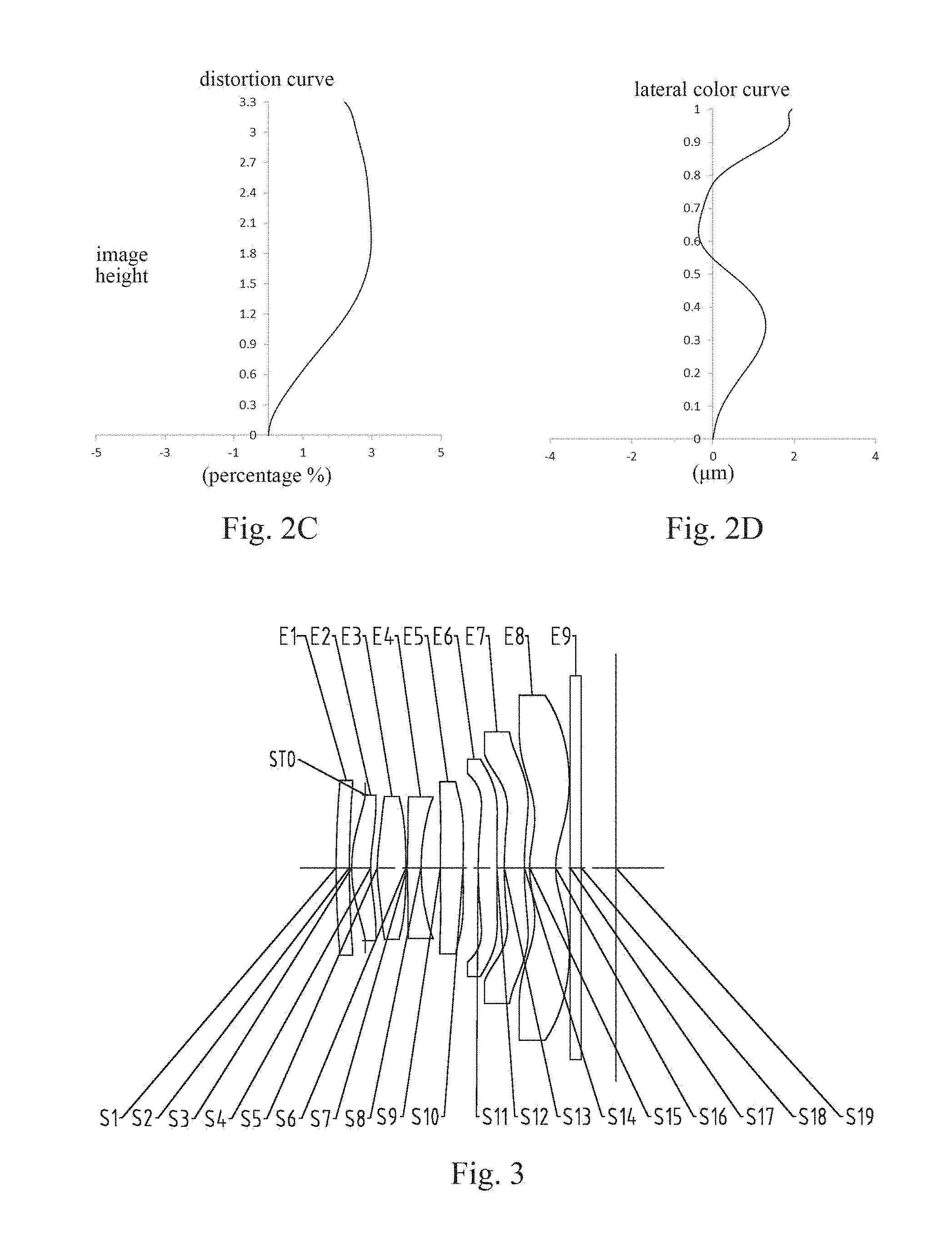
[0032] FIG. 3 is a schematic structural diagram of an optical imaging lens assembly according to a second embodiment of the present disclosure;
[0033] FIGS. 4A-4D respectively illustrate an axial color aberration curve, an astigmatic curve, a distortion curve, and a lateral color aberration curve of the optical imaging lens assembly according to the second embodiment;
[0034] FIG. 5 is a schematic structural diagram of an optical imaging lens assembly according to a third embodiment of the present disclosure;
[0035] FIGS. 6A-6D respectively illustrate an axial color aberration curve, an astigmatic curve, a distortion curve, and a lateral color aberration curve of the optical imaging lens assembly according to the third embodiment;
[0036] FIG. 7 is a schematic structural diagram of an optical imaging lens assembly according to a fourth embodiment of the present disclosure;
[0037] FIGS. 8A-8D respectively illustrate an axial color aberration curve, an astigmatic curve, a distortion curve, and a lateral color aberration curve of the optical imaging lens assembly according to the fourth embodiment;
[0038] FIG. 9 is a schematic structural diagram of an optical imaging lens assembly according to a fifth embodiment of the present disclosure;
[0039] FIGS. 10A-10D respectively illustrate an axial color aberration. curve, an astigmatic curve, a distortion curve, and a lateral color aberration. curve of the optical imaging lens assembly according to the fifth embodiment;
[0040] FIG. 11 is a schematic structural diagram of an optical imaging lens assembly according to a sixth embodiment of the present disclosure;
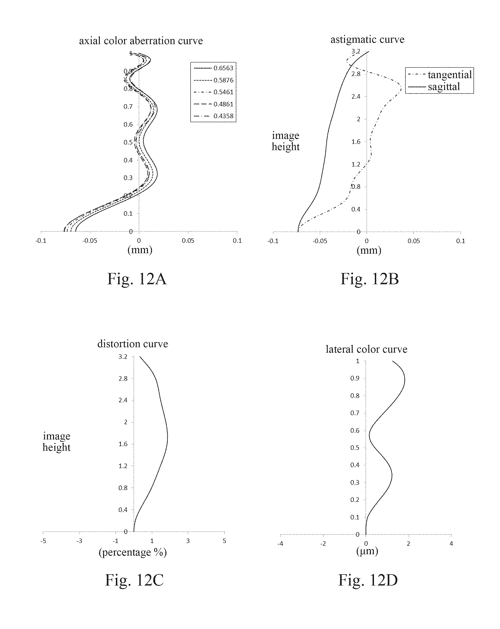
[0041] FIGS. 12A-12D respectively illustrate an axial color aberration curve, an astigmatic curve, a distortion curve, and a lateral color aberration curve of the optical imaging lens assembly according to the sixth embodiment;
[0042] FIG. 13 is a schematic structural diagram of an optical imaging lens assembly according to a seventh embodiment of the present disclosure;
[0043] FIGS. 14A-14D respectively illustrate an axial color aberration curve, an astigmatic curve, a distortion curve, and a lateral color aberration curve of the optical imaging lens assembly according to the seventh embodiment;
[0044] FIG. 15 is a schematic structural diagram of an optical imaging lens assembly according to an eighth embodiment of the present disclosure;
[0045] FIGS. 16A-16D respectively illustrate an axial color aberration curve, an astigmatic curve, a distortion curve, and a lateral color aberration curve of the optical imaging lens assembly according to the eighth embodiment;
[0046] FIG. 17 is a schematic structural diagram of an optical imaging lens assembly according to a ninth embodiment of the present disclosure;
[0047] FIGS. 18A-18D respectively illustrate an axial color aberration curve, an astigmatic curve, a distortion curve, and a lateral color aberration curve of the optical imaging lens assembly according to the ninth embodiment;
[0048] FIG. 19 is a schematic structural diagram of an optical imaging lens assembly according to a tenth embodiment of the present disclosure;
[0049] FIGS. 20A-20D respectively illustrate an axial color aberration curve, an astigmatic curve, a distortion curve, and a lateral color aberration curve of the optical imaging lens assembly according to the tenth embodiment;
[0050] FIG. 21 is a schematic structural diagram of an optical imaging lens assembly according to an eleventh embodiment of the present disclosure;
[0051] FIGS. 22A-22D respectively illustrate an axial color aberration curve, an astigmatic curve, a distortion curve, and a lateral color aberration curve of the optical imaging lens assembly according to the eleventh embodiment;
[0052] FIG. 23 is a schematic structural diagram of an optical imagine lens assembly according to a twelfth embodiment of the present disclosure;
[0053] FIGS. 24A-24D respectively illustrate an axial color aberration curve, an astigmatic curve, a distortion curve, and a lateral color aberration curve of the optical imaging lens assembly according to the twelfth embodiment;
[0054] FIG. 25 is a schematic structural diagram of an optical imaging lens assembly according to a thirteenth embodiment of the present disclosure; and
[0055] FIGS. 26A-26D respectively illustrate an axial color aberration curve, an astigmatic curve, a distortion curve, and a lateral color aberration curve of the optical imaging lens assembly according to the thirteenth embodiment.
DETAILED DESCRIPTION
[0056] For a better understanding of the present disclosure, various aspects of the present disclosure will be described in more detail with reference to the accompanying drawings. It should be understood that the detailed description is merely an illustration for the exemplary implementations of the present disclosure rather than a limitation to the scope of the present disclosure in any way. Throughout the specification, the same reference numerals designate the same elements. The expression "and/or" includes any and all combinations of one or more of the associated listed items.
[0057] It should be noted that in the specification, the expressions, such as "first," and "second" are only used to distinguish one feature from another, rather than represent any limitations to the features. Thus, the first lens discussed below may also be referred to as the second lens without departing from the teachings of the present disclosure.
[0058] In the accompanying drawings, the thicknesses, sizes and shapes of the lenses have been slightly exaggerated for the convenience of explanation. Specifically, shapes of spherical surfaces or aspheric surfaces shown in the accompanying drawings are examples. That is, the shapes of the spherical surfaces or the aspheric surfaces are not limited to the shapes of the spherical surfaces or the aspheric surfaces shown in the accompanying drawings. The accompanying drawings are merely illustrative and not strictly drawn to scale.
[0059] It should be further understood that the terms "comprising," "including," "having" and variants thereof, when used in the specification, specify the presence of stated features, entireties, steps, operations, elements and/or components, but do not exclude the presence or addition of one or more other features, entireties, steps, operations, elements, components and/or combinations thereof. In addition, expressions, such as "at least one of," when preceding a list of listed features, modify the entire list of features rather than an individual element in the list. Further, the use of "may," when describing the implementations of the present disclosure, relates to "one or more implementations of the present disclosure." Also, the term "exemplary" is intended to refer to an example or illustration.
[0060] As used herein, the terms "substantially," "about" and similar terms are used to indicate an approximation rather than a degree, and are intended to be illustrative of the inherent deviations of measured or calculated values as recognized by those of ordinary skill in the art.
[0061] Unless otherwise defined, all terms (including technical and scientific terms) used herein have the same meaning as commonly understood by those of ordinary skill in the art to which the present disclosure belongs. It should be further understood that terms, such as those defined in commonly used dictionaries, should be interpreted as having a meaning that is consistent with their meaning in the context of the relevant art and will not be interpreted in an idealized or overly formal sense unless expressly so defined herein.
[0062] In addition, the paraxial area refers to an area in proximity to the optical axis. The first lens is the lens closest to the object and the eighth lens is the lens closest to the photosensitive element. In this text, the surface closest to the object in each lens is referred to as the object-side surface, and the surface closest to the image plane in each lens is referred to as the image-side surface.
[0063] It should also be noted that the embodiments in the present disclosure and the features in the embodiments may be combined with each other on a non-conflict basis. The present disclosure will be described below in detail with reference to the accompanying drawings and in combination with the embodiments.
[0064] The present disclosure is further described below with reference to the specific embodiments.
[0065] The optical imaging lens assembly according to exemplary implementations of the present disclosure has, a for example, eight lenses, i.e., a first lens, a second lens, a third lens, a fourth lens, a fifth lens, a sixth lens, a seventh lens, and an eighth lens. The eight lenses are arranged in sequence from an object side to an image side along an optical axis.
[0066] In the exemplary implementations, the first lens, the second lens, the fifth lens, the seventh lens, and the eighth lens each may have a positive focal power or a negative focal power. Each of the third lens and the sixth lens may have a positive focal power. The fourth lens may have a negative focal power. By reasonably controlling the distribution of positive and negative focal powers of the lenses, not only low-order aberrations of the control system may be effectively balanced, which makes the optical imaging lens assembly obtain a good image quality, but also an ultra-thin large aperture characteristic may be achieved.
[0067] In the exemplary implementations, an effective focal length f of the optical imaging lens assembly and a combined focal length f34 of the third lens and the fourth lens may satisfy: 0.5.ltoreq.f/f34<1.0, and more specifically, may further satisfy: 0.53f/f34<0.74. By reasonably configuring the combined. focal length of the third lens and the fourth. lens, it may be conductive to shortening the total length of the optical imaging lens assembly system, and may effectively correct the astigmatism at the same time.
[0068] In the exemplary implementations, an optical-axis distance TTL from an object-side surface of the first lens to an image plane of the optical imaging lens assembly and a half of a diagonal length ImgH of an effective pixel area on the image plane of the optical imaging lens assembly may satisfy: TTL/ImgH.ltoreq.1.7. Through this configuration, an aberration of the edge field may be reduced, and the size of the optical imaging lens assembly system is effectively compressed, which ensures the ultra-thin characteristic and the miniaturization requirement of the lens assembly.
[0069] In the exemplary implementations, the effective focal length f of the optical imaging lens assembly and an effective focal length f6 of the sixth lens may satisfy: 0<f/f6<0.5, and more specifically, may further satisfy: 0.31.ltoreq.f/f6.ltoreq.0.41. Through this configuration, the sixth lens undertakes a small positive focal power, which may be conductive to controlling the volume of the lens, improving a space utilization rate of the lens, and ensureing the satisfaction of the miniaturization requirement for the system.
[0070] In the exemplary implementations, the effective focal length f of the optical imaging lens assembly and a combined focal length f12 of the first lens and the second lens may satisfy: 0<f/f12<0.5, and more specifically, may further satisfy: 0.05.ltoreq.f(/f12.ltoreq.0.23. By reasonably configuring the combined focal length of the first lens and the second lens, it may be conductive to shortening a field curvature of the optical imaging lens assembly system, and reducing an axial spherical aberration.
[0071] In the exemplary implementations, the effective focal length f of the optical imaging lens assembly and an effective focal length f1 of the first lens may satisfy: |f/f1|.ltoreq.0.1, and more specifically, may further satisfy: |f/f1|.ltoreq.0.05. Through this configuration, the first lens undertakes a small focal power, so that the aspheric feature of the first lens is mainly used, which may be conductive to increasing an aperture and correcting an edge field aberration.
[0072] In the exemplary implementations, a radius R3 of curvature of an object-side surface of the second lens and a radius R4 of curvature of an image-side surface of the second lens may satisfy: 0.6<R3/R4<1.2, and more specifically, may further satisfy: 0.88.ltoreq.R3/R4.ltoreq.1.07. By reasonably controlling the radis of curvature of the second lens, object-side lights may be better converged and an axial color aberration of the optical imaging lens assembly system is reduced.
[0073] In the exemplary implementations, a center thickness CT2 of the second lens on the optical axis and a center thickness CT3 of the third lens on the optical axis may satisfy: 0.5<CT2/CT3<0.8, and more specifically, may further satisfy: 0.66.ltoreq.(CT2/CT3.ltoreq.0.69. Through this configuration, the lens group has a more reasonable space utilization rate, and meets an assembly process requirement, which reduces an assembly sensitivity of the second lens.
[0074] In the exemplary implementations, a radius R7 of curvature of an object-side surface of the fourth lens and a radius R8 of curvature of an image-side surface of the fourth lines may satisfy: 0<(R7-R8)/(R7+R8)<1.0, and more specifically, may further satisfy: 0.46.ltoreq.(R7-R8)/(R7+R8).ltoreq.0.54. Under the premise that the image plane satisfies the specification, by reasonably selecting the effective radii of the object-side surface and the image -side surface of the fourth lens, an incidence angle of lights may be reasonably reduced, thereby reducing the system sensitivity and ensuring the stability of the assembly.
[0075] In the exemplary implementations, the effective focal length f of the optical imaging lens assembly and an effective focal length f5 of the fifth lens may satisfy: |f/f5|.ltoreq.0.1, and more specifically, may further satisfy: |f/f5|.ltoreq.0.06. Through this configuration, the fifth lens undertakes a small focal power, so that the aspheric feature of the fifth lens is mainly used, which may effectively reduce a deflection angle of the Lights, and the sensitivity of the optical imaging lens assembly.
[0076] In the exemplary implementations, the effective focal length f of the optical imaging lens assembly and a radius R11 of curvature of an object-side surface of the sixth lens may satisfy: 0.5<f/R11<1.0, and more specifically, may further satisfy: 0.65.ltoreq.f//R11.ltoreq.0.85. By restricting the radius of curvature of the sixth lens within a reasonable range, it may be conductive to adjusting the field curvature and the astigmatism of the imaging edge to meet the peripheral image quality.
[0077] In the exemplary implementations, a center thickness CT6 of the sixth lens on the optical axis and a center thickness CT7 of the seventh lens on the optical axis may satisfy: 0.7<CT6/CT7<1.2, and more specifically, may further satisfy: 0.82.ltoreq.CT6/CT7.ltoreq.1.03. Through this configuration, the lens group has a more reasonable space utilization rate, and meets the assembly process requirement, which reduces the assembly sensitivity of the sixth lens and the seventh lens.
[0078] In the exemplary implementations, the effective focal length f of the optical imaging lens assembly and a combined focal length f78 of the seventh lens and the eighth lens may satisfy: -0.5<f/f78<0, and more specifically, may further satisfy: -0.381.ltoreq.f/f78.ltoreq.-0.25. By reasonably configuring the combined focal lengths of the seventh lens and the eighth lens, the seventh lens and the eighth lens undertake a small negative focal power, which may balance the change of the refractive power of the lens group, thereby improving the image quality.
[0079] In the exemplary implementations, a radius R13 of curvature of an object-side surface of the seventh lens and a radius R14 of curvature of an image-side surface of the seventh lens satisfy: |(R13-R14)/(R13+R14)|.ltoreq.10.5, and more specifically, may further satisfy: |(R13-R14)/(R13+R14)|10.43. Under the premise that the image plane satisfies the specification, by reasonably selecting the effective radii of the object-side surface and the image-side surface of the seventh lens, the exit angle of the lights can be reasonably adjusted to better match the sensor.
[0080] In the exemplary implementations, a radius R15 of curvature of an object-side surface of the eighth lens and a radius R16 of curvature of an image-side surface of the eighth lens satisfy: 1.ltoreq.R15/R16<1.5, and more specifically, may further satisfy: 1.08.ltoreq.R15/R16.ltoreq.1.4. By reasonably allocating the radii of curvature of the eighth lens, the system may obtain a smaller axial aberration.
[0081] In the exemplary implementations, the effective focal length f of the optical imaging lens assembly and an entrance pupil diameter EPD of the optical imaging lens assembly may satisfy: f/EPD.ltoreq.1.8, and more specifically, may further satisfy: f/EPD.ltoreq.1.73. Through this configuration, more sufficient lights can enter into the optical imaging lens assembly system, thereby improving the image quality.
[0082] In the exemplary implementations, the optical imaging lens assembly may also include an aperture STO for limiting light beams to adjust the amount of lights entering the lens assembly and improve the image quality. The optical imaging lens assembly according to the above implementations of the present disclosure may use multiple lenses, for example, eight lenses as described above. By reasonably distributing the focal power, and the surface type of each lens, the center thickness of each lens, the axial distances between the lenses, etc., the aperture of the optical imaging lens assembly may be effectively enlarged, the system sensitivity may be reduced, the miniaturization of the lens assembly may be ensured and the image quality may be improved, such that the optical imaging lens assembly is more conductive to the production and processing and applicable to portable electronic products. In the implementations of the present disclosure, at least one of the mirror surfaces of the lenses is an aspheric mirror surface. The aspheric lens is characterized in that the curvature continuously changes from the center of the lens to the periphery. Different from a spherical lens having a constant curvature from the center of the lens to the periphery, the aspheric lens has a better radius-of-curvature characteristic, and has advantages of improving a distortion aberration and an astigmatic aberration, which can make the visual field larger and more realistic. The use of the aspheric lens can eliminate as much as possible the aberrations that occur during the imaging, thereby improving the image quality. In addition, the use of the aspheric lens may also effectively reduce the number of lenses in the optical system.
[0083] However, it should be understood by those skilled in the art that the various results and advantages described in the present specification may be obtained by changing the number of the lenses constituting the lens assembly without departing from the technical solution claimed by the present disclosure. For example, although eight lenses are described as an example in the implementations, the optical imaging lens assembly is not limited to include eight lenses. If desired, the optical imaging lens assembly may also include other numbers of lenses.
[0084] Specific embodiments of the optical imaging lens assembly that may be applied to the above implementations are further described below with reference to the accompanying drawings.
First Embodiments
[0085] An optical imaging lens assembly according to a first embodiment of the present disclosure is described below with reference to FIGS. 1-2D.
[0086] FIG. 1 is a schematic structural diagram of the optical imaging lens assembly according to the first embodiment of the present disclosure. As shown in FIG. 1, the optical imaging lens assembly includes, along an optical axis, eight lenses E1-E8 arranged in sequence from an object side to an image side. The first lens E1 has an object-side surface S1 and an image-side surface S2. The second lens S2 has an object-side surface S3 and an image -side surface S4. The third lens E3 has an object-side surface S5 and an image-side surface S6. The fourth lens S4 has an object-side surface S7 and an image-side surface S8. The fifth lens E5 has an object-side surface S9 and an image-side surface S11 and an image-side surface S12. The seventh lens S7 has an object-side surface S13 and an image-side surface S14. The eighth lens E8 has an object-side surface S15 and an image-side surface S16.
[0087] In this embodiment, each of the first lens, the second lens, the third lens, the fifth lens, and the sixth lens has a positive focal power. Each of the fourth lens, the seventh lens, and the eighth lens has a negative focal power.
[0088] The optical imaging lens assembly in this embodiment further includes an aperture STO for limiting light beams. The optical imaging lens assembly according to the first embodiment may include an optical filter E9 having an object-side surface S17 and an image-side surface S18. The optical filter E9 may be used to correct color deviations. Lights from an object sequentially passes through the surfaces S1-S18 and finally forms an image on an image plane S19.
[0089] Table 1 shows the surface type, the radius of curvature, the thickness, the material and the conic coefficient of each lens of the optical imaging lens assembly in the first embodiment.
TABLE-US-00001 TABLE 1 material refrac- abbe conic surface surface radius of thick- tive num- coef- number type curvature ness index ber ficient OBJ spherical infinite infinite S1 aspheric 10.6144 0.2500 1.64 23.8 -24.2641 S2 aspheric 10.9492 0.3000 -27.9364 STO spherical infinite -0.2519 S3 aspheric 1.8448 0.3575 1.55 56.1 -14.9645 S4 aspheric 2.0720 0.1224 -18.0645 S5 aspheric 2.2830 0.5419 1.55 56.1 -16.3614 S6 aspheric -13.7026 0.0250 82.4227 S7 aspheric 9.2836 0.2600 1.67 20.4 42.3398 S8 aspheric 2.8417 0.3579 -14.9169 S9 aspheric 9.9531 0.4107 1.65 23.5 -89.2006 S10 aspheric 11.3299 0.2788 4.1190 S11 aspheric 5.9566 0.3488 1.55 56.1 -30.0462 S12 aspheric -300.0000 0.1535 99.0000 S13 aspheric 7.6853 0.3711 1.65 23.5 -43.2969 S14 aspheric 4.8957 0.1000 -99.0000 S15 aspheric 1.2842 0.4935 1.55 56.1 -7.2778 S16 aspheric 1.0220 0.2767 -3.9170 S17 spherical infinite 0.2100 1.52 64.2 S18 spherical infinite 0.6522 S19 spherical infinite
[0090] As may be obtained from Table 1, the radius R3 of curvature of the object-side surface S3 of the second lens E2 and the radius R4 of curvature of the image-side surface S4 of the second lens E2 satisfy: R3/R4=0.89. The center thickness CT2 of the second lens E2 on the optical axis and the center thickness CT3 of the third lens E3 on the optical axis satisfy: CT2/CT3=0.66. The radius R7 of curvature of the object-side surface S7 of the fourth lens E4 and the radius R8 of curvature of the image-side surface S0 of the fourth lens E4 satisfy: (R7-R8)/(R7+R8)=0.53. The center thickness CT6 of the sixth lens E6 on the optical axis and the center thickness CT7 of the seventh lens E7 on the optical axis satisfy: CT6/CT7=0.94. The radius R13 of curvature of the object-side surface S13 of the seventh lens E7 and the radius R14 of curvature of the image-side surface S14 of the seventh lens E7 satisfy: |)R13-R14)/(R13+R14)|=0.22. The radius R15 of curvature of the object-side surface S15 of the eighth lens E8 and the radius R16 of curvature of the image-side surface S16 of the eighth lens E8 satisfy: R15/R16=1.26.
[0091] In this embodiment, the optical imaging lens assembly having eight lenses is used as an example. By reasonably distributing the focal lengths and the surface types of the lenses, the aperture of the lens assembly is effectively enlarged, and the total length of the lens assembly is shortened, thereby ensuring the large aperture and the miniaturization of the lens assembly. Meanwhile, various types of aberrations are corrected, which improves the resolution and the image quality of the lens assembly. The surface type x of each aspheric surface is defined by the following formula:
x = ch 2 1 + 1 - ( k + 1 ) c 2 h 2 + Aih i . ( 1 ) ##EQU00001##
[0092] Here, x is the sag of the displacement of the aspheric surface from the vertex of the aspheric surface, at distance h from the optical axis; c is the paraxial curvature of the aspheric surface, and c=1/R (i.e., the paraxial curvature c is the reciprocal of the radius R of curvature in Table 1 above); k is the conic coefficient (given in Table 1 above); and Ai is the i.sup.th order correction coefficient of the aspheric surface. Table 2 below shows the high-order coefficients A.sub.4, A.sub.6, A.sub.8, A.sub.10, A.sub.12, A.sub.14, A.sub.16, A.sub.18, and A.sub.20 applicable to the mirror surfaces S1-S16 in the first embodiment.
TABLE-US-00002 TABLE 2 surface number A4 A6 A8 A10 A12 S1 1.6544E-02 -1.8273E-02 -1.0185E-01 3.2971E-01 -4.6198E-01 S2 4.7143E-02 -1.8248E-01 2.2519E-01 4.8389E-02 -4.7633E-01 S3 2.6035E-01 -6.0092E-01 9.9496E-01 -1.1345E+00 8.0539E-01 S4 5.2480E-02 -3.1857E-01 5.1288E-01 -6.6276E-01 6.2381E-01 S5 1.8194E-02 -1.8904E-01 3.0565E-01 -4.9328E-01 6.5985E-01 S6 -9.5318E-02 2.7730E-01 -8.3348E-01 1.3347E+00 -1.2095E+00 S7 -7.7286E-02 2.2631E-01 -4.8940E-01 2.0659E-01 7.3584E-01 S8 6.7695E-02 -5.9921E-02 2.5621E-01 -8.5846E-01 1.4562E+00 S9 -6.6859E-02 7.4114E-02 -1.4553E-01 2.8475E-01 -3.7173E-01 S10 -9.6113E-02 2.0071E-02 -3.3310E-02 2.8657E-02 1.9385E-02 S11 1.0949E-02 9.1659E-02 -2.8265E-01 3.4490E-01 -2.8517E-01 S12 3.6830E-02 -3.2221E-03 -4.1848E-02 8.0258E-03 1.0963E-02 S13 1.9386E-01 -4.0640E-01 4.4838E-01 -3.9587E-01 2.3226E-01 S14 9.5593E-02 -1.0860E-01 1.7447E-02 1.4693E-02 -9.1221E-03 S15 -2.2838E-01 7.1654E-02 5.8030E-04 -5.4569E-03 1.5220E-03 S16 -1.6490E-01 8.5549E-02 -3.1552E-02 8.3826E-03 -1.5611E-03 surface number A14 A16 A18 A20 S1 3.6847E-01 -1.7207E-01 4.3737E-02 -4.6680E-03 S2 6.1917E-01 -3.9380E-01 1.2789E-01 -1.6922E-02 S3 -3.4969E-01 9.0578E-02 -1.2872E-02 7.7300E-04 S4 -3.5919E-01 1.1872E-01 -2.0768E-02 1.4931E-03 S5 -4.8956E-01 1.8504E-01 -3.2236E-02 1.8178E-03 S6 6.4252E-01 -1.9785E-01 3.2679E-02 -2.2402E-03 S7 -1.3269E+00 9.7920E-01 -3.4779E-01 4.8603E-02 S8 -1.3647E+00 7.2452E-01 -2.0169E-01 2.2671E-02 S9 2.9133E-01 -1.3033E-01 3.0519E-02 -2.8974E-03 S10 -5.0447E-02 3.6123E-02 -1.1211E-02 1.2885E-03 S11 1.5988E-01 -5.7875E-02 1.2090E-02 -1.0883E-03 S12 -6.3453E-03 1.4316E-03 -1.5162E-04 6.2634E-06 S13 -8.4347E-02 1.8427E-02 -2.2330E-03 1.1564E-04 S14 2.4379E-03 -3.5726E-04 2.7758E-05 -8.9215E-07 S15 -2.0784E-04 1.5452E-05 -5.8039E-07 8.1372E-09 S16 1.9384E-04 -1.5028E-05 6.5001E-07 -1.1868E-08
[0093] Table 3 below shows the effective focal lengths f1-f8 of the lenses in the first embodiment, the effective focal length f of the optical imaging lens assembly, the half of the maximal field-of-view HFOV of the optical imaging lens assembly, and the optical-axis distance TTL from the object-side surface S1 of the first lens E1 to the image plane S19 of the optical imaging lens assembly.
TABLE-US-00003 TABLE 3 f1 (mm) 419.80 f7 (mm) -22.06 f2 (mm) 19.79 f8 (mm) -27.35 f3 (mm) 3.62 f (mm 3.86 f4 (mm) -6.24 TTL (mm) 5.26 f5 (mm) 113.69 HFOV (.degree.) 40.4 f6 (mm) 10.69
[0094] According to Table 3, the effective focal length f of the optical imaging lens assembly and the effective focal length f1 of the first lens E1 satisfy: |f/f11=0.01. The effective focal length f of the optical imaging lens assembly and the effective focal length f5 of the fifth lens E5 satisfy: |f/f5|=0.03. The effective focal length f of the optical imaging lens assembly and the effective focal length f6 of the sixth lens E6 satisfy: f/f6=0.36.
[0095] In this embodiment, the effective focal length f of the optical imaging lens assembly and the combined focal length f12 of the first lens E1 and the second lens E2 satisfy: f/f12=0.2. The effective focal length f of the optical imaging lens assembly and the combined focal length f34 of the third lens E3 and the fourth lens E4 satisfy: f/f34=0.54. The effective focal length f of the optical imaging lens assembly and the radius R11 of curvature of the object-side surface S11 of the sixth lens E6 satisfy: f/R11=0.65. The effective focal length f of the optical imaging lens assembly and the combined focal length f78 of the seventh lens E7 and the eighth lens E8 satisfy: f/f78=-0.34. The effective focal length f of the optical imaging lens assembly and the entrance pupil diameter EPD of the optical imaging lens assembly satisfy: f/EPD-1.67. The optical-axis distance TTL from the object-side surface of the first lens to the image plane of the optical imaging lens assembly and the half of the diagonal length ImgH of the effective pixel area on the image plane of the optical imaging lens assembly satisfy: TTL/ImgH=1.59.
[0096] FIG. 2A illustrates an axial color aberration curve of the optical imaging lens assembly according to the first embodiment, representing deviations of focal points where lights of different wavelengths converge after passing through the optical imaging lens assembly. FIG. 2B illustrates an astigmatic curve of the optical imaging lens assembly according to the first embodiment, representing a curvature of a tangential image plane and a curvature of a sagittal image plane. FIG. 2C illustrates a distortion curve of the optical imaging lens assembly according to the first embodiment, representing degrees of distortion at different viewing angles. FIG. 2D illustrates a lateral color curve of the optical imaging lens assembly according to the first embodiment, representing deviations of different image heights on an image plane after lights pass through the optical imaging lens assembly. It can be seen from FIGS. 2A-2D that the optical imaging lens assembly according to the first embodiment can achieve a good image quality.
Second Embodiment
[0097] An optical imaging lens assembly according to a second embodiment of the present disclosure is described below with reference to FIGS. 3-4D. Except the parameters of the lenses in the optical imaging lens assembly, for example, except the radius of curvature, the thickness, the conic coefficient, the effective focal length of each lens, the axial spacing distances between the lenses, and the high-order coefficient of each mirror surface, etc., the optical imaging lens assemblies described in the second embodiment and the following embodiments have the same arrangement and same structure as the optical imaging lens assembly described in the first embodiment. For the purpose of brevity, the description of parts similar to those in the first embodiment will be omitted.
[0098] FIG. 3 is a schematic structural diagram of the optical imaging lens assembly according to the second embodiment of the present disclosure. As shown in FIG. 3, the optical imaging lens assembly according to the second embodiment includes first to eighth lenses E1-E8 having respective object-side surfaces and respective image-side surfaces.
[0099] In this embodiment, each of the first lens, the second lens, the third lens, the fifth lens, and the sixth lens has a positive focal power. Each of the fourth lens, the seventh lens, and the eighth lens has a negative focal power. Table 4 below shows the surface type, the radius of curvature, the thickness, the material and the conic coefficient of each lens of the optical imaging lens assembly in the second embodiment. Table 5 shows the high -order coefficients of the aspheric mirror surfaces in the second embodiment. Table 6 shows the effective focal lengths f1-f8 of the lenses in the second embodiment, the effective focal length f of the optical imaging lens assembly, the half of the maximal field-of-view HFOV of the optical imaging lens assembly, and the optical-axis distance TTL from the object-side surface SI of the first lens E1 to the image plane S19 of the optical imaging lens assembly. The surface type of each aspheric surface may be defined by the formula (1) given in the first embodiment.
TABLE-US-00004 TABLE 4 material refrac- abbe conic surface surface radius of Thick- tive num- coef- number type curvature ness index ber ficient OBJ spherical infinite Infinite S1 aspheric 12.4451 0.2500 1.64 23.8 -24.4053 S2 aspheric 13.2216 0.3000 -30.5456 STO spherical infinite -0.2559 S3 aspheric 1.8497 0.3615 1.55 56.1 -14.8503 S4 aspheric 2.0847 0.1245 -18.0693 S5 aspheric 2.2985 0.5418 1.55 56.1 -16.4828 S6 aspheric -13.7727 0.0250 81.6935 S7 aspheric 9.2582 0.2600 1.67 20.4 42.1167 S8 aspheric 2.8275 0.3668 -14.9611 S9 aspheric 10.6612 0.4325 1.65 23.5 -94.0599 S10 aspheric 12.0386 0.2830 1.7137 S11 aspheric 5.9767 0.3555 1.55 56.1 -29.0911 S12 aspheric -121.4285 0.1410 99.0000 S13 aspheric 8.2907 0.3780 1.65 23.5 -37.1581 S14 aspheric 5.1116 0.1000 -99.0000 S15 aspheric 1.2920 0.4925 1.55 56.1 -7.0020 S16 aspheric 1.0231 0.2775 -3.8172 S17 spherical infinite 0.2100 1.52 64.2 S18 spherical infinite 0.6530 S19 spherical infinite
TABLE-US-00005 TABLE 5 surface number A4 A6 A8 A10 A12 S1 1.8300E-02 -2.5888E-02 -7.9868E-02 2.8215E-01 -3.9487E-01 S2 5.1242E-02 -2.0409E-01 2.8079E-01 -5.8822E-02 -3.2140E-01 S3 2.6033E-01 -6.0465E-01 9.9339E-01 -1.1148E+00 7.8101E-01 S4 4.9951E-02 -3.0317E-01 4.6128E-01 -5.6186E-01 5.1424E-01 S5 1.5209E-02 -1.7425E-01 2.4925E-01 -3.6240E-01 4.8655E-01 S6 -1.0520E-01 3.1080E-01 -8.7298E-01 1.3465E+00 -1.1900E+00 S7 -8.5516E-02 2.5363E-01 -5.2549E-01 2.5802E-01 6.2919E-01 S8 6.4465E-02 -3.2827E-02 1.2733E-01 -5.0498E-01 8.7832E-01 S9 -6.5972E-02 7.4116E-02 -1.5307E-01 3.0262E-01 -3.9479E-01 S10 -8.9412E-02 -3.3205E-03 3.3797E-02 -8.4890E-02 1.3622E-01 S11 1.2588E-02 7.2812E-02 -2.3776E-01 2.9179E-01 -2.4574E-01 S12 4.1499E-02 -1.2942E-02 -3.4339E-02 7.4838E-03 8.8427E-03 S13 1.9201E-01 -4.0124E-01 4.4107E-01 -3.8966E-01 2.2942E-01 S14 9.0589E-02 -1.0264E-01 1.4450E-02 1.5557E-02 -9.2215E-03 S15 -2.2964E-01 7.1032E-02 2.2913E-04 -4.7544E-03 1.2136E-03 S16 -1.6785E-01 8.7785E-02 -3.2789E-02 8.8755E-03 -1.6897E-03 surface number A14 A16 A18 A20 S1 3.1033E-01 -1.4234E-01 3.5516E-02 -3.7207E-03 S2 4.6865E-01 -3.0403E-01 9.8483E-02 -1.2886E-02 S5 -3.3597E-01 8.6468E-02 -1.2230E-02 7.3171E-04 S4 -2.9235E-01 9.5839E-02 -1.6658E-02 1.1911E-03 S3 -3.5944E-01 1.3068E-01 -2.0548E-02 8.1950E-04 S6 6.1977E-01 -1.8763E-01 3.0523E-02 -2.0633E-03 S7 -1.1726E+00 8.5757E-01 -2.9990E-01 4.1209E-02 S8 -7.9343E-01 3.9165E-01 -9.7230E-02 9.1233E-03 S9 3.0807E-01 -1.3684E-01 3.1758E-02 -2.9854E-03 S10 -1.2479E-01 6.4333E-02 -1.7013E-02 1.7842E-03 S11 1.4155E-01 -5.2895E-02 1.1384E-02 -1.0490E-03 S12 -5.1674E-03 1.1542E-03 -1.2037E-04 4.8832E-06 S13 -8.3675E-02 1.8353E-02 -2.2311E-03 1.1580E-04 S14 2.4166E-03 -3.4831E-04 2.6631E-05 -8.4260E-07 S15 -1.4220E-04 7.8402E-06 -1.1729E-07 -3.4554E-09 S16 2.1503E-04 -1.7106E-05 7.5890E-07 -1.4197E-08
TABLE-US-00006 TABLE 6 f1 (mm) 293.99 f7 (mm) -21.68 f2 (mm) 19.45 f8 (mm) -25.50 f3 (mm) 3.65 f (mm) 3.89 f4 (mm) -6.20 TTL (mm) 5.30 f5 (mm) 128.63 HFOV (.degree.) 40.1 f6 (mm) 10.43
[0100] FIG. 4A illustrates an axial color aberration curve of the optical imaging lens assembly according to the second embodiment, representing deviations of focal points where lights of different. wavelengths converge after passing through the optical imaging lens assembly. FIG. 4B illustrates an astigmatic curve of the optical imaging lens assembly according to the second embodiment, representing a curvature of a tangential image plane and a curvature of a sagittal image plane. FIG. 4C illustrates a distortion curve of the optical imaging lens assembly according to the second embodiment, representing degrees of distortion at different viewing angles. FIG. 4D illustrates a lateral color curve of the optical imaging lens assembly according to the second embodiment, representing deviations of different image heights on an image plane after lights passes through the optical imaging lens assembly. It can be seen from FIGS. 4A-4D that the optical imaging lens assembly according to the second. embodiment can achieve a good image quality.
The Third Embodiment
[0101] An optical imaging lens assembly according to the third embodiment of the present disclosure is described below with reference to FIGS. 5-6D.
[0102] FIG. 5 is a schematic structural diagram of the optical imaging lens assembly according to the third embodiment of the present disclosure. As shown in FIG. 5, the optical imaging lens assembly according to the third. embodiment includes first to eighth lenses E1-E8 having repective object-side surfaces and respective image-side surfaces.
[0103] In this embodiment, each of the first lens, the second lens, the third lens, the fifth lens, the sixth lens, and the eighth lens has a positive focal power. Each of the fourth lens, and the seventh lens has a negative focal power.
[0104] Table 7 below shows the surface type, the radius of curvature, the thickness, the material and the conic coefficient of each lens of the optical imaging lens assembly in the third embodiment. Table 8 shows the high -order coefficients of the aspheric mirror surfaces in the third embodiment. Table 9 shows the effective focal lengths f1-f8 of the lenses in the third embodiment, the effective focal length f of the optical imaging lens assembly, the half of the maximal field-of-view HIV of the optical imaging lens assembly, and the optical-axis distance TIL from the object-side surface S1 of the first lens E1 to the image plane S19 of the optical imaging lens assembly. The surface type of each aspheric surface may be defined by the formula (1) given in the first embodiment.
TABLE-US-00007 TABLE 7 material refrac- abbe conic surface surface radius of thick- tive num- coef- number type curvature ness index ber ficient OBJ spherical infinite infinite S1 aspheric 15.8474 0.2500 1.64 23.8 -24.8345 S2 aspheric 17.8793 0.3000 -37.2277 STO spherical infinite -0.2628 S3 aspheric 1.8560 0.3686 1.55 56.1 -14.6476 S4 aspheric 2.1077 0.1272 -18.0807 S5 aspheric 2.3250 0.5423 1.55 56.1 -16.5339 S6 aspheric -13.9349 0.0250 81.7327 S7 aspheric 9.1928 0.2600 1.67 20.4 41.8299 S8 aspheric 2.8100 0.3843 -14.9439 S9 aspheric 11.6407 0.4428 1.65 23.5 -99.0000 S10 aspheric 13.0170 0.2850 4.6782 S11 aspheric 5.5780 0.3447 1.55 56.1 -26.5711 S12 aspheric 69.7384 0.1251 -99.0000 S13 aspheric 8.1669 0.3727 1.65 23.5 -27.9773 S14 aspheric 4.0593 0.1000 -68.3969 S15 aspheric 1.3073 0.5482 1.55 56.1 -6.9808 S16 aspheric 1.1231 0.2750 -3.4225 S17 spherical infinite 0.2100 1.52 64.2 S18 spherical infinite 0.6506 S19 spherical infinite
TABLE-US-00008 TABLE 8 surface number A4 A6 A8 A10 A12 S1 1.9336E-02 -3.1201E-02 -5.7429E-02 2.2347E-01 -3.0713E-01 S2 5.1110E-02 -2.0614E-01 2.9430E-01 -1.1557E-01 -1.9910E-01 S3 2.5482E-01 -5.8544E-01 9.4425E-01 -1.0354E+00 7.1106E-01 S4 4.6132E-02 -2.7631E-01 3.8108E-01 -4.2231E-01 3.7294E-01 S5 1.3104E-02 -1.5971E-01 2.0283E-01 -2.6928E-01 3.7272E-01 S6 -1.0760E-01 3.1023E-01 -8.2753E-01 1.2370E+00 -1.0665E+00 S7 -8.8603E-02 2.5218E-01 -5.0298E-01 2.6932E-01 4.9109E-01 S8 6.2704E-02 -1.4998E-02 2.3099E-02 -1.9239E-01 3.5441E-01 S9 -6.3786E-02 7.1626E-02 -1.5292E-01 3.0005E-01 -3.8564E-01 S10 -8.4667E-02 -1.5971E-02 6.8408E-02 -1.3859E-01 1.8547E-01 S11 1.3497E-02 6.7121E-02 -2.3444E-01 3.0644E-01 -2.6963E-01 S12 6.2265E-02 -6.1782E-02 1.6058E-02 -1.9614E-02 1.6635E-02 S13 1.9647E-01 -4.0935E-01 4.4367E-01 -3.8332E-01 2.2279E-01 S14 7.5709E-02 -8.9808E-02 9.8010E-03 1.6184E-02 -9.0853E-03 S15 -2.0415E-01 4.4857E-02 1.3165E-02 -8.5048E-03 1.8974E-03 S16 -1.6916E-01 8.7763E-02 -3.3253E-02 9.2151E-03 -1.7940E-03 surface number A14 A16 A18 A20 S1 2.3366E-01 -1.0348E-01 2.4928E-02 -2.5220E-03 S2 3.2604E-01 -2.1160E-01 6.7069E-02 -8.5181E-03 S3 -3.0112E-01 7.6522E-02 -1.0707E-02 6.3430E-04 S4 -2.0970E-01 6.8344E-02 -1.1824E-02 8.4223E-04 S5 -2.8112E-01 1.0231E-01 -1.5845E-02 5.9333E-04 S6 5.4288E-01 -1.6079E-01 2.5606E-02 -1.6956E-03 S7 -9.4198E-01 6.7995E-01 -2.3311E-01 3.1346E-02 S8 -2.7665E-01 9.4312E-02 -5.4135E-03 -2.5824E-03 S9 2.9633E-01 -1.2951E-01 2.9555E-02 -2.7309E-03 S10 -1.5179E-01 7.2673E-02 -1.8284E-02 1.8506E-03 S11 1.5868E-01 -5.9520E-02 1.2700E-02 -1.1524E-03 S12 -6.2776E-03 1.1978E-03 -1.1428E-04 4.3507E-06 S13 -8.0874E-02 1.7735E-02 -2.1599E-03 1.1239E-04 S14 2.3341E-03 -3.3129E-04 2.4963E-05 -7.7861E-07 S15 -2.2196E-04 1.3641E-05 -3.5795E-07 9.1772E-10 S16 2.3248E-04 -1.8754E-05 8.4109E-07 -1.5873E-08
TABLE-US-00009 TABLE 9 f1 (mm) 207.81 f7 (mm) -12.97 f2 (mm) 18.74 f8 (mm) 281.29 f3 (mm) 3.69 f (mm) 3.94 f4 (mm) -6.16 TTL (mm) 5.35 f5 (mm) 151.57 HFOV (.degree.) 39.7 f6 (mm) 11.07
[0105] FIG. 6A illustrates an axial color aberration curve of the optical imaging lens assembly according to the third embodiment, representing deviations of focal points where lights of different wavelengths converge after passing through the optical imaging lens assembly. FIG. 6B illustrates an astigmatic curve of the optical imaging lens assembly according to the third embodiment, representing a curvature of a tangential image plane and a curvature of a sagittal image plane. FIG. 6C illustrates a distortion curve of the optical imaging lens assembly according to the third embodiment, representing degrees of distortion at different viewing angles. FIG. 6D illustrates a lateral color curve of the optical imaging lens assembly according to the third embodiment, representing deviations of different image heights on an image plane after lights pass through the optical imaging lens assembly. It can be seen from FIGS. 6A-6D that the optical imaging lens assembly according to the third embodiment can achieve a good image quality.
Fourth Embodiment
[0106] An optical imaging lens assembly according to a fourth embodiment of the present disclosure is described below with reference to FIGS. 7-8D.
[0107] FIG. 7 is a schematic structural diagram of the optical imaging lens assembly according to the fourth embodiment of the present disclosure. As shown in FIG. 7, the optical imaging lens assembly according to the fourth embodiment includes first to eighth lenses E1-E8 having respective object-side surfaces and respective image-side surfaces.
[0108] In this embodiment, each of the first lens, the second lens, the third lens, the sixth lens, and the eighth lens has a positive focal power. Each of the fourth lens, the fifth lens, and the seventh lens has a negative focal power.
[0109] Table 10 below shows the surface type, the radius of curvature, the thickness, the material and the conic coefficient of each lens of the optical imaging lens assembly in the fourth. embodiment. Table 11 shows the high -order coefficients of the aspheric mirror surfaces in the fourth embodiment. Table 12 shows the effective focal lengths f1-f8 of the lenses in the fourth embodiment, the effective focal length f of the optical imaging lens assembly, the half of the maximal field-of-view HFOV of the optical imaging lens assembly, and the optical-axix distance TTL from the object-side surface S1 of the first lens E1 to the image plane S19 of the optical imaging lens assembly. The surface type of each aspheric surface may be defined by the formula (1) given in the first embodiment.
TABLE-US-00010 TABLE 10 Material refrac- abbe conic surface surface radius of thick- tive num- coef- number type curvature ness index ber ficient OBJ spherical infinite infinite S1 aspheric 40.0000 0.2500 1.64 23.8 -225.8938 S2 aspheric 122.6582 0.3000 -99.0000 STO spherical infinite -0.2545 S3 aspheric 1.9851 0.3454 1.55 56.1 -15.0576 S4 aspheric 2.0506 0.1031 -16.1597 S5 aspheric 2.4196 0.5247 1.55 56.1 -17.1049 S6 aspheric -12.8473 0.0590 78.2577 S7 aspheric 8.5808 0.3146 1.67 20.4 40.3223 S8 aspheric 3.0910 0.4686 -17.5113 S9 aspheric 9.3997 0.3480 1.65 23.5 -93.5229 S10 aspheric 9.0608 0.2908 0.4254 S11 aspheric 4.8227 0.3466 1.55 56.1 -32.5684 S12 aspheric 18.1550 0.1682 58.0172 S13 aspheric 8.9414 0.4203 1.65 23.5 -15.9950 S14 aspheric 3.5922 0.1000 -46.5965 S15 aspheric 1.3129 0.5992 1.55 56.1 -6.3593 S1 aspheric 1.2158 0.2706 -3.1941 S17 spherical infinite 0.2100 1.52 64.2 S18 spherical infinite 0.6653 S19 spherical infinite
TABLE-US-00011 TABLE 11 surface number A4 A6 A8 A10 A12 S1 1.1831E-02 -2.4531E-02 -4.2902E-02 1.6664E-01 -2.2075E-01 S2 6.6925E-02 -2.5085E-01 4.1083E-01 -3.5810E-01 1.4917E-01 S3 2.4449E-01 -5.5151E-01 8.4199E-01 -8.7585E-01 5.7469E-01 S4 5.1225E-02 -2.3457E-01 2.0072E-01 -1.4196E-01 1.5474E-01 S5 1.0290E-02 -1.1658E-01 6.3851E-02 -8.3207E-02 2.5259E-01 S6 -1.0737E-01 1.6516E-01 -2.9449E-01 3.7231E-01 -2.9087E-01 S7 -1.0323E-01 1.5921E-01 -2.3953E-01 2.1279E-01 -6.1339E-02 S8 4.5794E-02 5.1733E-03 -9.1739E-02 2.4047E-01 -4.0301E-01 S9 -5.8318E-02 9.2929E-02 -2.1623E-01 3.5547E-01 -3.7517E-01 S10 -1.0926E-01 1.1848E-01 -2.2035E-01 2.5554E-01 -1.7132E-01 S11 -3.1611E-02 1.7486E-01 -3.5440E-01 3.6707E-01 -2.5064E-01 S12 2.5543E-02 1.8013E-02 -1.0077E-01 8.8172E-02 -4.1290E-02 S13 1.9604E-01 -3.5758E-01 3.4727E-01 -2.7071E-01 1.4393E-01 S14 8.4834E-02 -1.0223E-01 3.4104E-02 -4.2292E-03 -2.5566E-04 S15 -1.6140E-01 2.0188E-02 1.6084E-02 -6.9677E-03 1.2238E-03 S16 -1.4815E-01 6.7781E-02 -2.3101E-02 6.0271E-03 -1.1403E-03 surface number A14 A16 A18 A20 S1 1.6133E-01 -6.8883E-02 1.6092E-02 -1.5889E-03 S2 9.4079E-03 -3.9129E-02 1.5889E-02 -2.1672E-03 S3 -2.3295E-01 5.6632E-02 -7.5735E-03 4.2869E-04 S4 -1.1666E-01 4.6614E-02 -9.2927E-03 7.3468E-04 S5 -2.5696E-01 1.1532E-01 -2.3639E-02 1.7551E-03 S6 1.3638E-01 -3.7253E-02 5.4626E-03 -3.3280E-04 S7 -7.1783E-02 8.6799E-02 -3.7005E-02 5.7623E-03 S8 4.3977E-01 -2.8534E-01 9.9860E-02 -1.4373E-02 S9 2.4292E-01 -9.1708E-02 1.8405E-02 -1.5139E-03 S10 5.9550E-02 -5.8662E-03 -1.8045E-03 3.7446E-04 S11 1.1574E-01 -3.5419E-02 6.4820E-03 -5.2632E-04 S12 1.1775E-02 -2.0218E-03 1.9079E-04 -7.5647E-06 S13 -4.8080E-02 9.6945E-03 -1.0818E-03 5.1402E-05 S14 1.5345E-04 -2.1283E-05 1.3993E-06 -3.7699E-08 S15 -1.0239E-04 2.4540E-06 1.7964E-07 -9.4393E-09 S16 1.4517E-04 -1.1509E-05 5.0565E-07 -9.3109E-09
TABLE-US-00012 TABLE 12 f1 (mm) 92.59 f7 (mm) -9.61 f2 (mm) 39.72 f8 (mm) 25.46 f3 (mm) 3.77 f (mm) 4.11 f4 (mm) -7.41 TTL (mm) 5.53 f5 (mm) -652.32 HFOV (.degree.) 38.9 f6 (mm) 11.91
[0110] FIG. 8A illustrates an axial color aberration curve of the optical imaging lens assembly according to the fourth embodiment, representing deviations of focal points where lights of different wavelengths converge after passing through the optical imaging lens assembly. FIG. 8B illustrates an astigmatic curve of the optical imaging lens assembly according to the fourth embodiment, representing a curvature of a tangential image plane and a curvature of a sagittal image plane. FIG. 8C illustrates a distortion curve of the optical imaging lens assembly according to the fourth embodiment, representing degrees of distortion at different viewing angles. FIG. 8D illustrates a lateral color curve of the optical imaging lens assembly according to the fourth embodiment, representing deviations of different image heights on an image plane after lights pass through the optical imaging lens assembly. It can be seen from FIGS. 8A-8D that the optical imaging lens assembly according to the fourth embodiment can achieve a good image quality.
Fifth Embodiment
[0111] An optical imaging lens assembly according to a fifth embodiment of the present disclosure is described below with reference to FIGS. 9-10D.
[0112] FIG. 9 is a schematic structural diagram of the optical imaging lens assembly according to the fifth embodiment of the present disclosure. As shown in FIG. 9, the optical imaging lens assembly according to the fifth embodiment includes first to eighth lenses E1-E8 having respective object-side surfaces and respective image-side surfaces.
[0113] In this embodiment, each of the first lens, the second lens, the third lens, the sixth lens, and the seventh lens has a positive focal power. Each of the fourth lens, the fifth lens, and the eighth lens has a negative focal power.
[0114] Table 13 below shows the surface type, the radius of curvature, the thickness, the material and the conic coefficient of each lens of the optical imaging lens assembly in the fifth embodiment. Table 14 shows the high -order coefficients of the aspheric mirror surfaces in the fifth embodiment. Table 15 shows the effective focal lengths f1-f8 of the lenses in the fifth embodiment, the effective focal length f of the optical imaging lens assembly, the half of the maximal field-of-view HFOV of the optical imaging lens assembly, and the optical-axis distance TTL from the object-side surface S1 of the first lens E1 to the image plane S19 of the optical imaging lens assembly. The surface type of each aspheric surface may be defined by the formula (1) given in the first embodiment.
TABLE-US-00013 TABLE 13 material refrac- abbe conic surface surface radius of thick- tive num- coef- number type curvature ness index ber ficient OBT spherical infinite infinite S1 aspheric 31.9514 0.2500 1.64 23.8 -133.8765 S2 aspheric 80.7125 0.3000 99.0000 STO spherical infinite -0.2450 S3 aspheric 1.9934 0.3559 1.55 56.1 -15.4778 S4 aspheric 1.9073 0.0880 -16.5029 S5 aspheric 2.2267 0.5265 1.55 56.1 -16.6828 S6 aspheric -14.3531 0.0484 88.7543 S7 aspheric 8.9155 0.3271 1.67 20.4 42.4148 S8 aspheric 3.1984 0.4466 -17.3344 S9 aspheric 10.0147 0.3770 1.65 23.5 -99.0000 S10 aspheric 8.5949 0.2813 -0.4524 S11 aspheric 5.6281 0.4112 1.55 56.1 -38.5387 S12 aspheric 300.0000 0.1977 99.0000 S13 aspheric 8.0768 0.3995 1.65 23.5 -25.9402 S14 aspheric 8.3277 0.1000 -40.7698 S15 aspheric 1.4541 0.4838 1.55 56.1 -6.2464 S16 aspheric 1.0389 0.2825 -3.7504 S17 spherical infinite 0.2100 1.52 64.2 S18 spherical infinite 0.6772 S19 spherical infinite
TABLE-US-00014 TABLE 14 surface number A4 A6 A8 A10 A12 S1 1.5905E-02 -3.8154E-02 -3.2506E-02 1.9625E-01 -2.9503E-01 S2 7.2785E-02 -3.0145E-01 5.5459E-01 -5.5965E-01 3.0162E-01 S3 2.4722E-01 -6.0521E-01 1.0015E+00 -1.1019E+00 7.5323E-01 S4 8.4937E-02 -3.7337E-01 4.3955E-01 -3.7703E-01 3.0285E-01 S5 2.6568E-02 -1.6171E-01 8.1893E-02 -1.8719E-02 1.6417E-01 S6 -1.1895E-01 2.2023E-01 -4.3880E-01 5.9609E-01 -5.0186E-01 S7 -1.0653E-01 1.9760E-01 -3.2580E-01 2.6992E-01 1.8474E-02 S8 4.4553E-02 1.1975E-02 -9.3798E-02 2.0072E-01 -3.0349E-01 S9 -6.2612E-02 9.7560E-02 -2.3491E-01 4.0744E-01 -4.5176E-01 S10 -1.0104E-01 8.3646E-02 -1.5243E-01 1.6955E-01 -9.9552E-02 S11 -1.1823E-02 9.1324E-02 -2.0684E-01 2.0499E-01 -1.3897E-01 S12 -8.2278E-03 4.4702E-02 -9.2580E-02 6.1770E-02 -2.3092E-02 S13 1.5853E-01 -2.7508E-01 2.4197E-01 -1.8442E-01 9.8714E-02 S14 1.1264E-01 -1.3410E-01 4.8345E-02 -6.5159E-03 -7.1234E-04 S15 -1.9049E-01 4.5272E-02 3.1217E-03 -2.3355E-03 1.0529E-04 S16 -1.4297E-01 6.5908E-02 -2.0948E-02 4.8272E-03 -8.0119E-04 surface number A14 A16 A18 A20 S1 2.3460E-01 -1.0698E-01 2.6428E-02 -2.7452E-03 S2 -4.7517E-02 -3.5843E-02 2.0332E-02 -3.2042E-03 S3 -3.1571E-01 7.9033E-02 -1.0854E-02 6.2968E-04 S4 -1.7795E-01 6.2715E-02 -1.1715E-02 8.9268E-04 S5 -2.1179E-01 1.0559E-01 -2.3164E-02 1.8231E-03 S6 2.5476E-01 -7.5513E-02 1.2021E-02 -7.9453E-04 S7 -2.5959E-01 2.3987E-01 -9.4912E-02 1.4219E-02 S8 3.2530E-01 -2.1397E-01 7.6702E-02 -1.1320E-02 S9 3.0674E-01 -1.2146E-01 2.5574E-02 -2.2073E-03 S10 2.0465E-02 7.5529E-03 -4.4315E-03 5.9633E-04 S11 6.6955E-02 -2.2458E-02 4.6324E-03 -4.2320E-04 S12 5.5585E-03 -8.6524E-04 7.8700E-05 -3.1275E-06 S13 -3.3101E-02 6.6768E-03 -7.4593E-04 3.5615E-05 S14 4.3841E-04 -7.6366E-05 6.3279E-06 -2.0919E-07 S15 7.3348E-05 -1.4600E-05 1.1025E-06 -3.0651E-08 S16 9.1557E-05 -6.6993E-06 2.7737E-07 -4.8739E-09
TABLE-US-00015 TABLE 15 f1 (mm) 82.43 f7 (mm) 255.86 f2 (mm) 175.42 f8 (mm) -11.32 f3 (mm) 3.57 f (mm) 4.07 f4 (mm) -7.65 TTL (mm) 5.52 f5 (mm) -104.91 HFOV (.degree.) 39.1 f6 (mm) 10.49
[0115] FIG. 10A illustrates an axial color aberration curve of the optical imaging lens assembly according to the fifth embodiment, representing deviations of focal points where lights of different wavelengths converge after passing through the optical imaging lens assembly. FIG. 10B illustrates an astigmatic curve of the optical imaging lens assembly according to the fifth embodiment, representing a curvature of a tangential image plane and a curvature of a sagittal image plane. FIG. 10C illustrates a distortion curve of the optical imaging lens assembly according to the fifth embodiment, representing degress of distortion at different viewing angles. FIG. 10D illustrates a lateral color curve of the optical imaging lens assembly according to the fifth embodiment, representing deviations of different image heights on an image plane after lights pass through the optical imaging lens assembly. It can be seen from FIGS. 10A-10D that the optical imaging lens assembly according to the fifth embodiment can achieve a good image quality.
Sixth Embodiment
[0116] An optical imaging lens assembly according to the sixth embodiment of the present disclosure is described below with reference to FIGS. 11-12D.
[0117] FIG. 11 is a schematic structural diagram of the optical imaging lens assembly according to the sixth embodiment of the present disclosure. As shown in FIG. 11, the optical imaging lens assembly according to the sixth embodiment includes first to eighth lenses E1-E8 having respective object-side surfaces and respective image-side surfaces.
[0118] In this embodiment, each of the first lens, the second lens, the third lens, the fifth lens, and the sixth lens has a positive focal power. Each of the fourth lens, the seventh lens, and the eighth lens has a negative focal power.
[0119] Table 16 below shows the surface type, the radius of curvature, the thickness, the material and the conic coefficient of each lens of the optical imaging lens assembly in the sixth embodiment. Table 17 shows the high -order coefficients of the aspheric mirror surfaces in the sixth embodiment. Table 18 shows the effective focal lengths f1-f8 of the lenses in the sixth embodiment, the effective focal length f of the optical imaging lens assembly, the half of the maximal field-of-view HFOV of the optical imaging lens assembly, and the optical-axis distance TTL from the object-side surface S1 of the first lens E1 to the image plane S19 of the optical imaging lens assembly. The surface type of each aspheric surface may be defined by the formula (1) given in the first embodiment.
TABLE-US-00016 TABLE 16 material refrac- abbe conic surface surface radius of thick- tive num- coef- number type curvature ness index ber ficient OBJ spherical infinite infinite S1 aspheric 40.0000 0.2500 1.55 56.1 -21.3820 S2 aspheric 40.1123 0.3000 -5.4865 STO spherical infinite -0.2480 S3 aspheric 1.8289 0.3730 1.55 56.1 -15.4209 S4 aspheric 1.9359 0.1253 -17.7254 S5 aspheric 2.1096 0.5441 1.55 56.1 -15.7186 S6 aspheric -13.9375 0.0557 89.8019 S7 aspheric 9.1286 0.2600 1.67 20.4 44.0757 S8 aspheric 2.7824 0.2993 -15.4738 S9 aspheric 7.3273 0.3686 1.65 23.5 -93.2779 S10 aspheric 8.5872 0.2695 5.1842 S11 aspheric 4.9347 0.3491 1.55 56.1 -27.7655 S12 aspheric 19.7139 0.1840 -76.4682 S13 aspheric 5.5254 0.3763 1.65 23.5 -62.8617 S14 aspheric 3.6349 0.0936 -91.1022 S15 aspheric 1.2671 0.5012 1.55 56.1 -8.0512 S16 aspheric 1.0529 0.2660 -4.5834 S17 spherical infinite 0.2100 1.52 64.2 S18 spherical infinite 0.6416 S19 spherical infinite
TABLE-US-00017 TABLE 17 surface number A4 A6 A8 A10 A12 S1 -1.4315E-05 4.3414E-05 8.8702E-06 7.3556E-05 -5.2208E-05 S2 -8.3651E-05 -4.6587E-05 4.5647E-05 -1.3876E-04 1.9039E-04 S3 2.3351E-01 -4.4367E-01 6.4491E-01 -7.4023E-01 5.4436E-01 S4 1.0760E-01 -4.7144E-01 6.9649E-01 -8.2470E-01 7.6223E-01 S5 4.9437E-02 -1.8191E-01 2.4211E-02 7.5848E-02 1.6479E-01 S6 -4.8348E-02 6.0300E-02 -3.7793E-01 7.9430E-01 -8.3196E-01 S7 -7.2673E-02 3.3108E-01 -1.2231E+00 2.3396E+00 -2.6285E+00 S8 7.4585E-02 -1.0074E-01 5.7027E-01 -1.9219E+00 3.4017E+00 S9 -8.0998E-02 1.3904E-01 -3.4997E-01 6.8943E-01 -8.3819E-01 S10 -1.2764E-01 1.0513E-01 -3.0212E-01 5.4144E-01 -5.5551E-01 S11 1.6904E-02 1.6715E-01 -5.7016E-01 8.1311E-01 -7.3014E-01 S12 7.0872E-02 -9.9267E-02 9.2306E-02 -1.0060E-01 6.3445E-02 S13 2.3838E-01 -5.1715E-01 5.1432E-01 -3.5456E-01 1.5879E-01 S14 1.5805E-01 -2.6180E-01 1.7629E-01 -7.6645E-02 2.2396E-02 S15 -2.4498E-01 1.2960E-01 -4.8551E-02 1.4960E-02 -3.3754E-03 S16 -1.6426E-01 9.4435E-02 -3.7604E-02 1.0043E-02 -1.7708E-03 surface number A14 A16 A18 A20 S1 3.6653E-05 -1.3273E-05 3.0258E-06 -1.8212E-07 S2 -1.4564E-04 7.4008E-05 -1.5966E-05 1.9826E-06 S3 -2.4299E-01 6.4044E-02 -9.1931E-03 5.5528E-04 S4 -4.4899E-01 1.5347E-01 -2.7779E-02 2.0615E-03 S5 -2.8622E-01 1.5647E-01 -3.6462E-02 3.0331E-03 S6 4.8548E-01 -1.5991E-01 2.7811E-02 -1.9876E-03 S7 1.7291E+00 -6.1343E-01 9.4570E-02 -2.1634E-03 S8 -3.4681E+00 2.0519E+00 -6.4860E-01 8.4285E-02 S9 6.0703E-01 -2.5539E-01 5.7495E-02 -5.3488E-03 S10 3.4223E-01 -1.2335E-01 2.3925E-02 -1.9318E-03 S11 4.1825E-01 -1.4717E-01 2.8897E-02 -2.4131E-03 S12 -2.1691E-02 4.0899E-03 -4.0229E-04 1.6167E-05 S13 -4.3783E-02 7.1777E-03 -6.4872E-04 2.5431E-05 S14 -4.2112E-03 4.7976E-04 -2.9853E-05 7.7317E-07 S15 5.0338E-04 -4.6250E-05 2.3602E-06 -5.1039E-08 S16 2.0060E-04 -1.3958E-05 5.4045E-07 -8.8752E-09
TABLE-US-00018 TABLE 18 f1 (mm) 14632.00 f7 (mm) -17.87 f2 (mm) 27.13 f8 (mm) -65.83 f3 (mm) 3.39 f (mm) 3.74 f4 (mm) -6.10 TTL (mm) 5.22 f5 (mm) 69.46 HFOV (.degree.) 41.3 f6 (mm) 11.94
[0120] FIG. 12A illustrates an axial color aberration curve of the optical imaging lens assembly according to the sixth embodiment, representing deviations of focal points where lights of different wavelengths converge after passing through the optical imaging lens assembly. FIG. 12B illustrates an astigmatic curve of the optical imaging lens assembly according to the sixth embodiment, representing a curvature of a tangential image plane and a curvature of a sagittal image plane. FIG. 12C illustrates a distortion curve of the optical imaging lens assembly according to the sixth embodiment, representing degrees of distortion at different viewing angles. FIG. 12D illustrates a lateral color curve of the optical imaging lens assembly according to the sixth embodiment, representing deviations of different image heights on an image plane after lights pass through the optical imaging lens assembly. It can be seen from FIGS. 12A-12D that the optical imaging lens assembly according to the sixth embodiment can. achieve a good image quality.
Seventh Embodiment
[0121] An optical imaging lens assembly according to the seventh embodiment of the present disclosure is described below with reference to FIGS. 13-14D.
[0122] FIG. 13 is a schematic structural diagram of the optical imaging lens assembly according to the seventh embodiment of the present. disclosure. As shown in FIG. 13, the optical imaging lens assembly according to the seventh embodiment includes first. to eighth lenses E1-E8 having respective object-side surfaces and respective image-side surfaces.
[0123] In this embodiment, each of the second lens, the third lens, the fifth lens, and the sixth lens has a positive focal power. Each of the first lens, the fourth lens, the seventh lens, and the eighth lens has a negative focal power.
[0124] Table 19 below shows the surface type, the radius of curvature, the thickness, the material and the conic coefficient of each lens of the optical imaging lens assembly in the seventh embodiment. Table 20 shows the high-order coefficients of the aspheric mirror surfaces in the seventh embodiment. Table 21 shows the effective focal lengths f1-f8 of the lenses in the seventh embodiment, the effective focal length f of the optical imaging lens assembly, the half of the maximal field-of-view HFOV of the optical imaging lens assembly, and the optical-axis distance TTL from the object-side surface S1 of the first lens E1 to the image plane S19 of the optical imaging lens assembly. The surface type of each aspheric surface may be defined by the formula (1) given in the first embodiment.
TABLE-US-00019 TABLE 19 material refrac- abbe conic surface surface radius of thick- tive num- coef- number type curvature ness index ber ficient OBJ spherical infinite infinite S1 aspheric 30.0000 0.2500 1.64 23.8 -15.2240 S2 aspheric 28.8912 0.3000 -10.7150 STO spherical infinite -0.2497 S3 aspheric 1.8311 0.3712 1.55 56.1 -15.4163 S4 aspheric 1.9418 0.1238 -17.7056 S5 aspheric 2.1140 0.5415 1.55 56.1 -15.7159 S6 aspheric -13.9074 0.0535 89.5788 S7 aspheric 9.1435 0.2600 1.67 20.4 44.0360 S8 aspheric 2.7570 0.3001 -15.5014 S9 aspheric 7.1646 0.3799 1.65 23.5 -93.8170 S10 aspheric 8.5418 0.2750 4.6262 S11 aspheric 5.0105 0.3489 1.55 56.1 -27.7813 S12 aspheric 20.0259 0.1840 -80.2619 S13 aspheric 5.4981 0.3818 1.65 23.5 -62.9529 S14 aspheric 3.7037 0.0967 -85.9382 S15 aspheric 1.2793 0.5012 1.55 56.1 -7.9349 S1 aspheric 1.0480 0.2662 -4.5816 S17 spherical infinite 0.2100 1.52 64.2 S18 spherical infinite 0.6417 S19 spherical infinite
TABLE-US-00020 TABLE 20 surface number A4 A6 A8 A10 A12 S1 1.8679E-03 -2.7328E-03 7.3471E-03 -2.5475E-02 3.7929E-02 S2 9.2908E-03 -7.9700E-02 3.1895E-01 -7.1719E-01 9.5674E-01 S3 2.3500E-01 -4.6649E-01 7.1655E-01 -8.3982E-01 6.2008E-01 S4 1.0964E-01 -4.9746E-01 7.8106E-01 -9.4730E-01 8.5788E-01 S5 5.7574E-02 -2.4028E-01 2.0219E-01 -2.2672E-01 4.7538E-01 S6 -4.2826E-02 3.4033E-02 -3.3277E-01 7.5525E-01 -8.1264E-01 S7 -6.6061E-02 2.8224E-01 -1.0576E+00 2.0063E+00 -2.2026E+00 S8 7.1167E-02 -8.2417E-02 5.1164E-01 -1.7987E+00 3.2405E+00 S9 -8.1739E-02 1.3562E-01 -3.3073E-01 6.4942E-01 -7.9406E-01 S10 -1.2678E-01 9.7383E-02 -2.7256E-01 4.8491E-01 -4.9417E-01 S11 1.5810E-02 1.7913E-01 -6.0971E-01 8.7888E-01 -7.9236E-01 S12 7.7993E-02 -1.1463E-01 1.0827E-01 -1.1064E-01 6.7440E-02 S13 2.4546E-01 -5.4265E-01 5.6100E-01 -4.0484E-01 1.9104E-01 S14 1.5630E-01 -2.5781E-01 1.7334E-01 -7.5674E-02 2.2257E-02 S15 -2.4625E-01 1.3189E-01 -5.0898E-02 1.6168E-02 -3.7202E-03 S16 -1.6300E-01 9.2717E-02 -3.6850E-02 9.8549E-03 -1.7366E-03 surface number A14 A16 A18 A20 S1 -2.7071E-02 9.7317E-03 -1.6082E-03 8.2029E-05 S2 -7.7349E-01 3.7268E-01 -9.8619E-02 1.1052E-02 S3 -2.7685E-01 7.2950E-02 -1.0470E-02 6.3243E-04 S4 -4.9199E-01 1.6460E-01 -2.9314E-02 2.1484E-03 S5 -4.8194E-01 2.3025E-01 -5.1694E-02 4.3551E-03 S6 4.7972E-01 -1.5885E-01 2.7697E-02 -1.9816E-03 S7 1.3841E+00 -4.4338E-01 4.8315E-02 3.1408E-03 S8 -3.3399E+00 1.9916E+00 -6.3314E-01 8.2616E-02 S9 5.7937E-01 -2.4556E-01 5.5655E-02 -5.2089E-03 S10 3.0244E-01 -1.0807E-01 2.0727E-02 -1.6509E-03 S11 4.5304E-01 -1.5856E-01 3.0919E-02 -2.5639E-03 S12 -2.2701E-02 4.2467E-03 -4.1589E-04 1.6671E-05 S13 -5.6199E-02 9.9906E-03 -9.9430E-04 4.3188E-05 S14 -4.2094E-03 4.8160E-04 -3.0051E-05 7.7968E-07 S15 5.6126E-04 -5.1966E-05 2.6676E-06 -5.7985E-08 S16 1.9617E-04 -1.3592E-05 5.2374E-07 -8.5593E-09
TABLE-US-00021 TABLE 21 f1 (mm) -1338.65 f7 (mm) -19.20 f2 (mm) 26.90 f8 (mm) -45.33 f3 (mm) 3.40 f (mm) 3.80 f4 (mm) -6.01 TTL (mm) 5.24 f5 (mm) 62.17 HFOV (.degree.) 38.2 f6 (mm) 12.13
[0125] FIG. 14A illustrates an axial color aberration curve of the optical imaging lens assembly according to the seventh embodiment, representing deviations of focal points where lights of different wavelengths converge after passing through the optical imaging lens assembly. FIG. 14B illustrates an astigmatic curve of the optical imaging lens assembly according to the seventh embodiment, representing a curvature of a tangential image plane and a curvature of a sagittal image plane. FIG. 14C illustrates a distortion curve of the optical imaging lens assembly according to the seventh embodiment, representing degrees of distortion at different viewing angles. FIG. 14D illustrates a lateral color curve of the optical imaging lens assembly according to the seventh embodiment, representing deviations of different image heights on an image plane after lights pass through the optical imaging lens assembly. It can be seen from FIGS. 14A-14D that the optical imaging lens assembly according to the seventh embodiment can achieve a good image quality.
Eighth Embodiment
[0126] An optical imaging lens assembly according to an eighth embodiment of the present disclosure is described below with reference to FIGS. 15-16D.
[0127] FIG. 15 is a schematic structural diagram of the optical imaging lens assembly according to the eighth embodiment of the present disclosure. As shown in FIG. 15, the optical imaging lens assembly according to the eighth embodiment includes first to eighth lenses E1-E8 having respective object-side surfaces and respective image-side surfaces.
[0128] In this embodiment, each of the second lens, the third lens, the fifth lens, and the sixth lens has a positive focal power. Each of the first lens, the fourth lens, the seventh lens, and the eighth lens has a negative focal power.
[0129] Table 22 below shows the surface type, the radius of curvature, the thickness, the material and the conic coefficient of each lens of the optical imaging lens assembly in the eighth embodiment. Table 23 shows the high -order coefficients of the aspheric mirror surfaces is the eighth. embodiment. Table 24 shows the effective focal lengths f1-f8 of the lenses in the eighth embodiment, the effective focal length f of the optical imaging lens assembly, the half of the maximal field-of-view HFOV of the optical imaging lens assembly, and the optical-axis distance TTL from the object-side surface S1 of the first lens E1 to the image plane S19 of the optical imaging lens assembly. The surface type of each aspheric surface may be defined by the formula (1) given in the first embodiment.
TABLE-US-00022 TABLE 22 material refrac- abbe conic surface surface radius of thick- tive num- coef- number type curvature ness index ber ficient OBJ spherical infinite infinite S1 aspheric 30.0000 0.2500 1.64 23.8 -13.9860 S2 aspheric 28.9129 0.3000 -11.5086 STO spherical infinite -0.2405 0.0000 S3 aspheric 1.8308 0.3701 1.55 56.1 -15.4137 S4 aspheric 1.9394 0.1234 -17.7099 S5 aspheric 2.1104 0.5392 1.55 56.1 -15.7115 S6 aspheric -14.0081 0.0530 89.5064 S7 aspheric 9.1002 0.2600 1.67 20.4 44.0386 S8 aspheric 2.7601 0.2924 -15.5136 S9 aspheric 7.2071 0.3737 1.65 23.5 -93.6597 S10 aspheric 8.5658 0.2731 4.4169 S11 aspheric 5.0952 0.3475 1.55 56.1 -27.4459 S12 aspheric 21.6325 0.1832 -94.4619 S13 aspheric 5.4604 0.3808 1.65 23.5 -60.6875 S14 aspheric 4.0411 0.0949 -86.4479 S15 aspheric 1.2900 0.5001 1.55 56.1 -7.9297 S16 aspheric 1.0520 0.2638 -4.5825 S17 spherical infinite 0.2100 1.52 64.2 S18 spherical infinite 0.6393 S19 spherical infinite
TABLE-US-00023 TABLE 23 surface number A4 A6 A8 A10 A12 S1 -1.5540E-03 2.1830E-02 -6.7818E-02 1.0021E-01 -8.7804E-02 S2 6.4635E-03 -5.4902E-02 2.2879E-01 -5.3931E-01 7.4802E-01 S3 2.3665E-01 -4.7494E-01 7.3577E-01 -8.6357E-01 6.3732E-01 S4 1.0818E-01 -4.9029E-01 7.6414E-01 -9.2541E-01 8.4140E-01 S5 6.0289E-02 -2.5774E-01 2.5335E-01 -3.0848E-01 5.5217E-01 S6 -4.2433E-02 2.7444E-02 -3.1158E-01 7.2476E-01 -7.8849E-01 S7 -6.4213E-02 2.6477E-01 -9.8113E-01 1.8228E+00 -1.9466E+00 S8 6.8864E-02 -6.8762E-02 4.8256E-01 -1.7711E+00 3.2301E+00 S9 -8.0341E-02 1.2533E-01 -3.0127E-01 6.0571E-01 -7.5613E-01 S10 -1.2823E-01 1.1023E-01 -3.1241E-01 5.4365E-01 -5.4197E-01 S11 1.3186E-02 1.9522E-01 -6.4617E-01 9.2488E-01 -8.2796E-01 S12 7.7832E-02 -1.1835E-01 1.1423E-01 -1.1519E-01 6.9470E-02 S13 2.4636E-01 -5.3889E-01 5.5160E-01 -3.9486E-01 1.8512E-01 S14 1.5464E-01 -2.5524E-01 1.7135E-01 -7.4787E-02 2.2012E-02 S15 -2.4310E-01 1.2670E-01 -4.7140E-02 1.4682E-02 -3.3739E-03 S16 -1.6356E-01 9.2091E-02 -3.6730E-02 9.8358E-03 -1.7331E-03 surface number A14 A16 A18 A20 S1 5.0448E-02 -1.9215E-02 4.4113E-03 -4.5409E-04 S2 -6.2398E-01 3.0864E-01 -8.3575E-02 9.5623E-03 S3 -2.8440E-01 7.4919E-02 -1.0752E-02 6.4941E-04 S4 -4.8456E-01 1.6263E-01 -2.9031E-02 2.1314E-03 S5 -5.2565E-01 2.4514E-01 -5.4498E-02 4.5808E-03 S6 4.6844E-01 -1.5575E-01 2.7230E-02 -1.9520E-03 S7 1.1713E+00 -3.3963E-01 2.0923E-02 6.1627E-03 S8 -3.3403E+00 1.9924E+00 -6.3295E-01 8.2511E-02 S9 5.5926E-01 -2.3911E-01 5.4504E-02 -5.1206E-03 S10 3.2510E-01 -1.1426E-01 2.1617E-02 -1.7018E-03 S11 4.7025E-01 -1.6361E-01 3.1741E-02 -2.6207E-03 S12 -2.3253E-02 4.3371E-03 -4.2407E-04 1.6985E-05 S13 -5.4100E-02 9.5485E-03 -9.4321E-04 4.0691E-05 S14 -4.1663E-03 4.7692E-04 -2.9765E-05 7.7216E-07 S15 5.1223E-04 -4.7806E-05 2.4728E-06 -5.4109E-08 S16 1.9575E-04 -1.3566E-05 5.2307E-07 -8.5562E-09
TABLE-US-00024 TABLE 24 f1 (mm) -1369.05 f7 (mm) -26.94 f2 (mm) 27.14 f8 (mm) -40.52 f3 (mm) 3.40 f (mm) 3.71 f4 (mm) -6.03 TTL (mm) 5.21 f5 (mm) 63.59 HFOV (.degree.) 38.8 f6 (mm) 12.11
[0130] FIG. 16A illustrates an axial color aberration curve of the optical imaging lens assembly according to the eighth embodiment, representing deviations of focal points where lights of different wavelengths converge after passing through the optical imaging lens assembly. FIG. 16B illustrates an astigmatic curve of the optical imaging lens assembly according to the eighth embodiment, representing a curvature of a tangential image plane and a curvature of a sagittal image plane. FIG. 16C illustrates a distortion curve of the optical imaging lens assembly according to the eighth embodiment, representing degrees of distortion at different viewing angles. FIG. 16D illustrates a lateral color curve of the optical imaging lens assembly according to the eighth embodiment, representing deviations of different image heights on an image plane after lights pass through the optical imaging lens assembly. It can be seen from FIGS. 16A-16D that the optical imaging lens assembly according to the eighth embodiment can achieve a good image quality.
Ninth Embodiment
[0131] An optical imaging lens assembly according to a ninth embodiment of the present disclosure is described below with reference to FIGS. 17-18D.
[0132] FIG. 17 is a schematic structural diagram of the optical imaging lens assembly according to the ninth embodiment of the present disclosure. As shown in FIG. 17, the optical imaging lens assembly according to the ninth embodiment includes first to eighth lenses E1-E8 having respective object-side surfaces and respective image-side surfaces.
[0133] In this embodiment, each of the first lens, the second lens, the third lens, and the sixth lens has a positive focal power. Each of the fourth lens, the fifth lens, the seventh lens, and the eighth lens has a negative focal power.
[0134] Table 25 below shows the surface type, the radius of curvature, the thickness, the material and the conic coefficient of each lens of the optical imaging lens assembly in the ninth embodiment. Table 26 shows the high -order coefficients of the aspheric mirror surfaces in the ninth embodiment. Table 27 shows the effective focal lengths f1-f8 of the lenses in the ninth embodiment, the effective focal length f of the optical imaging lens assembly, the half of the maximal field-of-view HFOV of the optical imaging lens assembly, and the optical-axis distance TTL from the object-side surface S1 of the first lens E1 to the image plane S19 of the optical imaging lens assembly. The surface type of each aspheric surface may be defined by the formula (1) given in the first embodiment.
TABLE-US-00025 TABLE 25 material refrac- abbe conic surface surface radius of thick- tive num- coef- number type curvature ness index ber ficient OBJ spherical infinite infinite S1 aspheric 26.8720 0.2500 1.64 23.8 -80.4313 S2 aspheric 53.8641 0.3000 99.0000 STO spherical infinite -0.2475 S3 aspheric 1.9669 0.3639 1.55 56.1 -15.5167 S4 aspheric 1.8800 0.0910 -16.8985 S5 aspheric 2.1883 0.5268 1.55 56.1 -16.6838 S6 aspheric -14.0465 0.0425 85.6876 S7 aspheric 9.0988 0.3028 1.67 20.4 41.5711 S8 aspheric 3.1188 0.4389 -17.0040 S9 aspheric 10.9609 0.3684 1.65 23.5 -99.0000 S10 aspheric 9.5468 0.2819 -2.1170 S11 aspheric 5.3049 0.4054 1.55 56.1 -36.0219 S12 aspheric 300.0000 0.1950 99.0000 S13 aspheric 7.8136 0.4005 1.65 23.5 -26.4376 S14 aspheric 5.0826 0.1000 -80.3828 S15 aspheric 1.3794 0.5196 1.55 56.1 -6.3497 S16 aspheric 1.0805 0.2778 -3.5946 S17 spherical infinite 0.2100 1.52 64.2 S18 spherical infinite 0.6725 S19 spherical infinite
TABLE-US-00026 TABLE 26 surface number A4 A6 A8 A10 A12 S1 1.7563E-02 -4.1324E-02 -1.9520E-02 1.6542E-01 -2.5608E-01 S2 6.4070E-02 -2.5446E-01 4.1175E-01 -2.8507E-01 -5.1954E-02 S3 2.4539E-01 -5.9378E-01 9.8806E-01 -1.1066E+00 7.7081E-01 S4 8.6771E-02 -3.9914E-01 5.3065E-01 -5.2486E-01 4.3320E-01 S5 2.7897E-02 -1.9911E-01 2.0658E-01 -2.1720E-01 3.5813E-01 S6 -9.3678E-02 1.1945E-01 -2.4259E-01 3.8621E-01 -3.7270E-01 S7 -7.7141E-02 1.0345E-01 -2.0200E-01 2.4934E-01 -1.4063E-01 S8 6.0144E-02 -2.6193E-02 -3.6120E-02 1.1705E-01 -1.9787E-01 S9 -5.8787E-02 8.1722E-02 -1.9929E-01 3.6252E-01 -4.2091E-01 S10 -9.8595E-02 7.0185E-02 -1.3628E-01 1.6146E-01 -9.9811E-02 S11 7.2842E-04 7.4297E-02 -2.1416E-01 2.4729E-01 -1.9477E-01 S12 2.0322E-02 -7.7719E-03 -3.7627E-02 2.1908E-02 -4.3083E-03 S13 1.6427E-01 -3.1141E-01 3.0194E-01 -2.4080E-01 1.3079E-01 S14 9.3328E-02 -1.0844E-01 3.0891E-02 1.0110E-03 -2.8962E-03 S15 -2.0529E-01 6.0889E-02 -3.9120E-03 -6.7825E-04 -8.8509E-05 S16 -1.5343E-01 7.6234E-02 -2.6840E-02 6.9138E-03 -1.2654E-03 surface number A14 A16 A18 A20 S1 2.0598E-01 -9.4476E-02 2.3380E-02 -2.4240E-03 S2 2.5070E-01 -1.9187E-01 6.5962E-02 -8.8907E-03 S3 -3.2883E-01 8.3689E-02 -1.1675E-02 6.8759E-04 S4 -2.4432E-01 8.2229E-02 -1.4794E-02 1.0947E-03 S5 -3.3432E-01 1.5355E-01 -3.3558E-02 2.7666E-03 S6 2.0845E-01 -6.6160E-02 1.1076E-02 -7.6106E-04 S7 -3.8830E-02 1.0605E-01 -5.5470E-02 9.6295E-03 S8 2.3364E-01 -1.6637E-01 6.3737E-02 -9.9263E-03 S9 2.9709E-01 -1.2147E-01 2.6278E-02 -2.3223E-03 S10 2.2202E-02 7.2487E-03 -4.5608E-03 6.2953E-04 S11 1.0587E-01 -3.7917E-02 7.9247E-03 -7.1399E-04 S12 1.1834E-04 6.1111E-05 -6.1696E-06 9.6751E-08 S13 -4.4335E-02 9.0703E-03 -1.0324E-03 5.0421E-05 S14 8.6383E-04 -1.2891E-04 9.9902E-06 -3.1795E-07 S15 7.8776E-05 -1.3477E-05 9.8671E-07 -2.7306E-08 S16 1.5603E-04 -1.2080E-05 5.2242E-07 -9.5248E-09
TABLE-US-00027 TABLE 27 f1 (mm) 83.45 f7 (mm) -23.92 f2 (mm) 162.03 f8 (mm) -23.65 f3 (mm) 3.50 f (mm) 4.07 f4 (mm) -7.26 TTL (mm) 5.50 f5 (mm) -127.78 HFOV (.degree.) 39.2 f6 (mm) 9.88
[0135] FIG. 18A illustrates an axial color aberration curve of the optical imaging lens assembly according to the ninth embodiment, representing deviations of focal points where lights of different wavelengths converge after passing through the optical imaging lens assembly. FIG. 18B illustrates an astigmatic curve of the optical imaging lens assembly according to the ninth embodiment, representing a curvature of a tangential image plane and a curvature of a sagittal image plane. FIG. 18C illustrates a distortion curve of the optical imaging lens assembly according to the ninth embodiment, representing degrees of distortion at different viewing angles. FIG. 18D illustrates a lateral color curve of the optical imaging lens assembly according to the ninth embodiment, representing deviations of different image heights on an image plane after lights pass through the optical imaging lens assembly. It can be seen from FIGS. 18A-18D that the optical imaging lens assembly according to the ninth embodiment can achieve a good image quality.
Tenth Embodiment
[0136] An optical imaging lens assembly according to a tenth embodiment of the present disclosure is described below with reference to FIGS. 19-20D.
[0137] FIG. 19 is a schematic structural diagram of the optical imaging lens assembly according to the tenth embodiment of the present disclosure. As shown in FIG. 19, the optical imaging lens assembly according to the tenth embodiment includes first to eighth lenses E1-E8 having respective object-side surfaces and respective image-side surfaces.
[0138] In this embodiment, each of the first lens, the second lens, the third lens, and the sixth lens has a positive focal power. Each of the fourth lens, the fifth lens, the seventh lens, and the eighth lens has a negative focal power.
[0139] Table 28 below shows the surface type, the radius of curvature, the thickness, the material and the conic coefficient of each lens of the optical imaging lens assembly in the tenth embodiment. Table 29 shows the high -order coefficients of the aspheric mirror surfaces in the tenth embodiment. Table 30 shows the effective focal lengths f1-f8 of the lenses in the tenth embodiment, the effective focal length f of the optical imaging lens assembly, the half of the maximal field-of-view HFOV of the optical imaging lens assembly, and the optical-axis distance TTL from the object-side surface S1 of the first lens E1 to the image plane S19 of the optical imaging lens assembly. The surface type of each aspheric surface may be defined by the formula (1) given in the first embodiment.
TABLE-US-00028 TABLE 28 material refrac- abbe conic surface surface radius of thick- tive num- coef- number type curvature ness index ber ficient OBJ spherical infinite infinite S1 aspheric 30.4755 0.2500 1.64 23.8 -178.5029 S2 aspheric 67.2497 0.3000 93.9283 STO spherical infinite -0.2456 S3 aspheric 1.9983 0.3513 1.55 56.1 -15.4408 S4 aspheric 1.9509 0.0897 -16.3113 S5 aspheric 2.2976 0.5268 1.55 56.1 -16.9256 S6 aspheric -12.8346 0.0435 78.0213 S7 aspheric 8.5724 0.3168 1.67 20.4 40.8274 S8 aspheric 3.1851 0.4636 -17.4010 S9 aspheric 9.6917 0.3725 1.65 23.5 -94.4315 S10 aspheric 8.4127 0.2894 -0.7097 S11 aspheric 5.5156 0.4080 1.55 56.1 -37.3823 S12 aspheric 799.6898 0.1862 99.0000 S13 aspheric 9.2690 0.4080 1.65 23.5 -28.1256 S14 aspheric 8.3201 0.1000 -49.0033 S15 aspheric 1.4129 0.4717 1.55 56.1 -6.5271 S16 aspheric 1.0158 0.2809 -3.8796 S17 spherical infinite 0.2100 1.52 64.2 S18 spherical infinite 0.6756 S19 spherical infinite
TABLE-US-00029 TABLE 29 surface number A4 A6 A8 A10 A12 S1 1.2972E-02 -2.6497E-02 -6.0451E-02 2.3476E-01 -3.2664E-01 S2 7.3501E-02 -2.9354E-01 5.1065E-01 -4.6812E-01 1.9704E-01 S3 2.5372E-01 -6.1523E-01 1.0006E+00 -1.0871E+00 7.3711E-01 S4 7.9193E-02 -3.4104E-01 3.6969E-01 -2.9686E-01 2.4928E-01 S5 2.5356E-02 -1.7132E-01 1.4746E-01 -1.8032E-01 3.7209E-01 S6 -1.1565E-01 2.0086E-01 -3.7970E-01 5.0151E-01 -4.1305E-01 S7 -1.0359E-01 1.7685E-01 -2.7961E-01 2.3013E-01 2.9488E-04 S8 4.9278E-02 -1.4961E-02 -1.2326E-02 3.9778E-02 -9.6895E-02 S9 -6.0144E-02 9.0133E-02 -2.2371E-01 3.9423E-01 -4.3935E-01 S10 -1.0172E-01 8.5335E-02 -1.5800E-01 1.7715E-01 -1.0482E-01 S11 -1.7438E-02 1.1562E-01 -2.5074E-01 2.5363E-01 -1.7508E-01 S12 -8.9633E-03 6.7182E-02 -1.2894E-01 8.9728E-02 -3.5408E-02 S13 1.6616E-01 -2.9294E-01 2.6772E-01 -2.1156E-01 1.1662E-01 S14 1.1786E-01 -1.4144E-01 5.4122E-02 -9.3723E-03 1.9110E-04 S15 -1.8740E-01 4.2442E-02 4.5537E-03 -2.9083E-03 2.7272E-04 S16 -1.4171E-01 6.4567E-02 -2.0532E-02 4.8460E-03 -8.3611E-04 surface number A14 A16 A18 A20 S1 2.5032E-01 -1.1151E-01 2.7085E-02 -2.7763E-03 S2 2.5036E-02 -6.6396E-02 2.7520E-02 -3.9291E-03 S3 -3.0728E-01 7.6628E-02 -1.0495E-02 6.0773E-04 S4 -1.5639E-01 5.7562E-02 -1.1041E-02 8.5561E-04 S5 -3.6509E-01 1.7063E-01 -3.7903E-02 3.2041E-03 S6 2.0530E-01 -5.9591E-02 9.2918E-03 -6.0176E-04 S7 -1.8871E-01 1.7745E-01 -7.0671E-02 1.0647E-02 S8 1.6010E-01 -1.3570E-01 5.6930E-02 -9.3069E-03 S9 2.9848E-01 -1.1802E-01 2.4790E-02 -2.1335E-03 S10 2.2535E-02 7.1167E-03 -4.3970E-03 5.9749E-04 S11 8.5041E-02 -2.8236E-02 5.6763E-03 -5.0337E-04 S12 8.8093E-03 -1.3722E-03 1.2171E-04 -4.6565E-06 S13 -4.0166E-02 8.2981E-03 -9.4561E-04 4.5820E-05 S14 2.5544E-04 -5.3462E-05 4.7219E-06 -1.6119E-07 S15 4.2136E-05 -1.1167E-05 9.0020E-07 -2.5741E-08 S16 9.9359E-05 -7.5022E-06 3.1775E-07 -5.6740E-09
TABLE-US-00030 TABLE 30 f1 (mm) 86.81 f7 (mm) -151.56 f2 (mm) 92.89 f8 (mm) -11.40 f3 (mm) 3.61 f (mm) 4.07 f4 (mm) -7.78 TTL (mm) 5.50 f5 (mm) -111.57 HFOV (.degree.) 39.1 f6 (mm) 10.16
[0140] FIG. 20A illustrates an axial color aberration curve of the optical imaging lens assembly according to the tenth embodiment, representing deviations of focal points where lights of different wavelengths converge after passing through the optical imaging lens assembly. FIG. 20B illustrates an astigmatic curve of the optical imaging lens assembly according to the tenth embodiment, representing a curvature of a tangential image plane and a curvature of a sagittal image plane. FIG. 20C illustrates a distortion curve of the optical imaging lens assembly according to the tenth embodiment, representing degrees of distortion at different viewing angles. FIG. 20D illustrates a lateral color curve of the optical imaging lens assembly according to the tenth embodiment, representing deviations of different image heights on an image plane after lights pass through the optical imaging lens assembly. It can be seen from FIGS. 20A-20D that the optical imaging lens assembly according to the tenth embodiment can achieve a good image quality.
Eleventh Embodiment
[0141] An optical imaging lens assembly according to an eleventh embodiment of the present disclosure is described below with reference to FIGS. 21-22D.
[0142] FIG. 21 is a schematic structural diagram of the optical imaging lens assembly according to the eleventh embodiment of the present disclosure. As shown in FIG. 21, the optical imaging lens assembly according to the eleventh embodiment includes first to eighth lenses E1-E8 having respective object-side surfaces and respective image-side surfaces.
[0143] In this embodiment, each of the first lens, the third lens, and the sixth lens has a positive focal power. Each of the second lens, the fourth lens, the fifth lens, the seventh lens, and the eighth lens has a negative focal power.
[0144] Table 31 below shows the surface type, the radius of curvature, the thickness, the material and the conic coefficient of each lens of the optical imaging lens assembly in the eleventh embodiment. Table 32 shows the high-order coefficients of the aspheric mirror surfaces in the eleventh embodiment. Table 33 shows the effective focal lengths f1-f8 of the lenses in the eleventh embodiment, the effective focal length f of the optical imaging lens assembly, the half of the maximal field-of-view HFOV of the optical imaging lens assembly, and the optical-axis distance TTL from the object-side surface S1 of the first lens E1 to the image plane S19 of the optical imaging lens assembly. The surface type of each aspheric surface may be defined by the formula (1) given in the first embodiment.
TABLE-US-00031 TABLE 31 material refrac- abbe conic surface surface radius of thick- tive num- coef- number type curvature ness index ber ficient OBJ spherical infinite infinite S1 aspheric 31.6958 0.2500 1.64 23.8 -139.7326 S2 aspheric 81.2098 0.3000 99.0000 STO spherical infinite -0.2487 S3 aspheric 1.9969 0.3582 1.55 56.1 -15.5892 S4 aspheric 1.8600 0.0840 -16.5591 S5 aspheric 2.1670 0.5222 1.55 56.1 -16.7145 S6 aspheric -14.2191 0.0516 85.5477 S7 aspheric 8.9884 0.3260 1.67 20.4 41.8909 S8 aspheric 3.1918 0.4455 -17.3934 S9 aspheric 10.3055 0.3688 1.65 23.5 -99.0000 S10 aspheric 9.0685 0.2801 -0.4367 S11 aspheric 5.3816 0.4116 1.55 56.1 -40.3426 S12 aspheric 300.0000 0.2000 99.0000 S13 aspheric 9.0768 0.3990 1.65 23.5 -23.5476 S14 aspheric 6.3277 0.1000 -56.2394 S15 aspheric 1.4244 0.5133 1.55 56.1 -6.2572 S16 aspheric 1.0754 0.2794 -3.7147 S17 spherical infinite 0.2100 1.52 64.2 S18 spherical infinite 0.6741 S19 spherical infinite
TABLE-US-00032 TABLE 32 surface number A4 A6 A8 A10 A12 S1 1.5660E-02 -3.6702E-02 -3.8571E-02 2.1345E-01 -3.2392E-01 S2 7.0396E-02 -2.8436E-01 4.9470E-01 -4.3186E-01 1.2795E-01 S3 2.4312E-01 -5.9282E-01 9.8224E-01 -1.0859E+00 7.4551E-01 S4 8.6926E-02 -3.8350E-01 4.5240E-01 -3.8161E-01 3.0122E-01 S5 3.0272E-02 -1.7981E-01 1.1630E-01 -5.6663E-02 1.9814E-01 S6 -1.1111E-01 1.8721E-01 -3.7027E-01 5.1764E-01 -4.5112E-01 S7 -1.0251E-01 1.9490E-01 -3.9944E-01 5.6242E-01 -5.0459E-01 S8 4.4956E-02 1.6072E-02 -1.2292E-01 2.7568E-01 -4.0994E-01 S9 -6.1389E-02 9.5492E-02 -2.2769E-01 3.9449E-01 -4.4044E-01 S10 -1.0607E-01 1.0349E-01 -2.0175E-03 2.4589E-01 -1.7386E-01 S11 -1.4512E-02 1.0552E-01 -2.4050E-01 2.4649E-01 -1.7047E-01 S12 -2.4107E-03 4.3092E-02 -9.9079E-02 6.8377E-02 -2.6074E-02 S13 1.6185E-01 -2.9198E-01 2.7043E-01 -2.1172E-01 1.1418E-01 S14 9.2977E-02 -1.0846E-01 3.0730E-02 1.4338E-03 -3.1085E-03 S15 -1.9305E-01 4.8614E-02 2.0910E-03 -2.5266E-03 2.6756E-04 S16 -1.4238E-01 6.5559E-02 -2.0921E-02 4.8076E-03 -7.8694E-04 surface number A14 A16 A18 A20 S1 2.6283E-01 -1.2278E-01 3.1132E-02 -3.3235E-03 S2 1.0121E-01 -1.1297E-01 4.2377E-02 -5.8670E-03 S3 -3.1349E-01 7.8661E-02 -1.0822E-02 6.2859E-04 S4 -1.7635E-01 6.2333E-02 -1.1695E-02 8.9516E-04 S5 -2.3699E-01 1.1775E-01 -2.6277E-02 2.1404E-03 S6 2.3616E-01 -7.1824E-02 1.1683E-02 -7.8661E-04 S7 2.5700E-01 -4.8304E-02 -1.0204E-02 4.0405E-03 S8 4.1751E-01 -2.6248E-01 9.0970E-02 -1.3117E-02 S9 3.0184E-01 -1.2058E-01 2.5591E-02 -2.2241E-03 S10 6.5443E-02 -8.7200E-03 -1.2242E-03 3.3199E-04 S11 8.2268E-02 -2.7086E-02 5.4198E-03 -4.8063E-04 S12 6.3205E-03 -9.7991E-04 8.8253E-05 -3.4694E-06 S13 -3.8306E-02 7.7026E-03 -8.5567E-04 4.0560E-05 S14 9.0670E-04 -1.3265E-04 1.0085E-05 -3.1543E-07 S15 3.7356E-05 -1.0741E-05 8.9701E-07 -2.6301E-08 S16 8.7685E-05 -6.2092E-06 2.4813E-07 -4.2104E-09
TABLE-US-00033 TABLE 33 f1 (mm) 81.03 f7 (mm) -34.35 f2 (mm) -662.87 f8 (mm) -16.73 f3 (mm) 3.48 f (mm) 4.10 f4 (mm) -7.59 TTL (mm) 5.53 f5 (mm) -132.63 HFOV (.degree.) 39.0 f6 (mm) 10.02
[0145] FIG. 22A illustrates an axial color aberration curve of the optical imaging lens assembly according to the eleventh embodiment, representing deviations of focal points where lights of different wavelengths converge after passing through the optical imaging lens assembly. FIG. 22B illustrates an astigmatic curve of the optical imaging lens assembly according to the eleventh embodiment, representing a curvature of a tangential image plane and a curvature of a sagittal image plane. FIG. 22C illustrates a distortion curve of the optical imaging lens assembly according to the eleventh embodiment, representing degrees of distortion at different viewing angles. FIG. 22D illustrates a lateral color curve of the optical imaging lens assembly according to the eleventh embodiment, representing deviations of different image heights on an image plane after lights pass through the optical imaging lens assembly. It can be seen from FIGS. 22A-22D that the optical imaging lens assembly according to the eleventh embodiment can achieve a good image quality.
Twelfth Embodiment
[0146] An optical imaging lens assembly according to a twelfth embodiment of the present disclosure is described below with reference to FIGS. 23-24D.
[0147] FIG. 23 is a schematic structural diagram of the optical imaging lens assembly according to the twelfth embodiment of the present disclosure. As shown in FIG. 23, the optical imaging lens assembly according to the twelfth embodiment includes first to eighth lenses E1-E8 having respective object-side surfaces and respective image-side surfaces.
[0148] In this embodiment, each of the first lens, the second lens, the third lens, the fifth lens, and the sixth lens has a positive focal power. Each of the fourth lens, the seventh lens, and the eighth lens has a negative focal power.
[0149] Table 34 below shows the surface type, the radius of curvature, the thickness, the material and the conic coefficient of each lens of the optical imaging lens assembly in the twelfth embodiment. Table 35 shows the high-order coefficients of the aspheric mirror surfaces in the twelfth embodiment. Table 36 shows the effective focal lengths f1-f8 of the lenses in the twelfth embodiment, the effective focal length f of the optical imaging lens assembly, the half of the maximal field-of-view HFOV of the optical imaging lens assembly, and the optical-axis distance TTL from the object-side surface S1 of the first lens E1 to the image plane S19 of the optical imaging lens assembly. The surface type of each aspheric surface may be defined by the formula (1) given in the first embodiment.
TABLE-US-00034 TABLE 34 material refrac- abbe conic surface surface radius of thick- tive num- coef- number type curvature ness index ber ficient OBJ spherical infinite infinite S1 aspheric 8.7121 0.2500 1.64 23.8 -22.0984 S2 aspheric 8.6838 0.3000 -24.8790 STO spherical infinite -0.2440 0.0000 S3 aspheric 1.8329 0.3580 1.55 56.1 -15.1904 S4 aspheric 2.0229 0.1179 -17.9006 S5 aspheric 2.2127 0.5402 1.55 56.1 -15.8923 S6 aspheric -13.7783 0.0333 86.9955 S7 aspheric 9.2176 0.2600 1.67 20.4 43.7827 S8 aspheric 2.8169 0.3174 -14.7507 S9 aspheric 8.1645 0.3787 1.65 23.5 -90.5642 S10 aspheric 9.4730 0.2789 2.6480 S11 aspheric 5.2276 0.3299 1.55 56.1 -30.3341 S12 aspheric 30.0000 0.1807 33.8767 S13 aspheric 5.9039 0.3734 1.65 23.5 -61.9630 S14 aspheric 4.4249 0.1000 -87.1682 S15 aspheric 1.3344 0.4883 1.55 56.1 -7.8785 S16 aspheric 1.0529 0.2690 -4.4213 S17 spherical infinite 0.2100 1.52 64.2 S18 spherical infinite 0.6446 S19 spherical infinite
TABLE-US-00035 TABLE 35 surface number A4 A6 A8 A10 A12 S1 9.6173E-03 -1.2341E-02 -4.2005E-02 1.4639E-01 -2.1037E-01 S2 2.5280E-02 -1.1330E-01 2.3148E-01 -2.7087E-01 1.8363E-01 S3 2.5128E-01 -5.5100E-01 9.1058E-01 -1.0730E+00 7.8328E-01 S4 8.1715E-02 -4.3102E-01 7.4698E-01 -9.9291E-01 9.2853E-01 S3 4.4977E-02 -2.6938E-01 4.4957E-01 -7.3056E-01 9.8246E-01 S6 -4.2475E-02 2.4577E-02 -2.8406E-01 6.6206E-01 -7.2189E-01 S7 -4.7652E-02 1.2301E-01 -4.5845E-01 6.6313E-01 -3.3003E-01 S8 7.5556E-02 -1.3351E-01 6.5809E-01 -2.0012E+00 3.3563E+00 S9 -8.0236E-02 1.0891E-01 -1.9873E-01 3.4228E-01 -3.9964E-01 S10 -1.2662E-01 9.0640E-02 -2.0689E-01 3.1876E-01 -2.8241E-01 S11 2.0994E-02 1.0337E-01 -3.6713E-01 4.8651E-01 -4.1840E-01 S12 5.6591E-02 -5.8177E-02 3.0218E-02 -4.9463E-02 3.9259E-02 S13 2.1561E-01 -4.5414E-01 4.7082E-01 -3.7664E-01 2.0498E-01 S14 1.3052E-01 -1.7802E-01 8.0673E-02 -1.9010E-02 1.9391E-03 S15 -2.2970E-01 9.7637E-02 -2.3515E-02 4.6698E-03 -8.9438E-04 S16 -1.5188E-01 7.5246E-02 -2.6052E-02 6.4012E-03 -1.1046E-03 surface number A14 A16 A18 A20 S1 1.7172E-01 -8.1696E-02 2.0986E-02 -2.2438E-03 S2 -5.5768E-02 -6.4195E-03 8.7647E-03 -1.6330E-03 S3 -3.4599E-01 9.0453E-02 -1.2908E-02 7.7610E-04 S4 -5.3239E-01 1.7641E-01 -3.1064E-02 2.2522E-03 S3 -7.6929E-01 3.2315E-01 -6.7587E-02 5.4595E-03 S6 4.2996E-01 -1.4328E-01 2.5096E-02 -1.8017E-03 S7 -2.2789E-01 3.8537E-01 -1.8448E-01 3.0599E-02 S8 -3.2832E+00 1.8721E+00 -5.7217E-01 7.2110E-02 S9 2.8831E-01 -1.2252E-01 2.7934E-02 -2.6264E-03 S10 1.4724E-01 -4.2346E-02 5.8503E-03 -2.6090E-04 S11 2.3542E-01 -8.3063E-02 1.6643E-02 -1.4344E-03 S12 -1.4889E-02 2.9630E-03 -3.0060E-04 1.2309E-05 S13 -7.0610E-02 1.4851E-02 -1.7524E-03 8.9204E-05 S14 2.0227E-04 -8.8230E-05 1.0184E-05 -4.1489E-07 S15 1.4024E-04 -1.4518E-05 8.3810E-07 -2.0209E-08 S16 1.2761E-04 -9.2305E-06 3.7327E-07 -6.3835E-09
TABLE-US-00036 TABLE 36 f1 (mm) 1705.58 f7 (mm) -30.39 f2 (mm) 21.44 f8 (mm) -23.61 f3 (mm) 3.53 f (m) 3.80 f4 (mm) -6.18 TTL (mm) 5.19 f5 (mm) 82.30 HFOV (.degree.) 40.8 f6 (mm) 11.53
[0150] FIG. 24A illustrates an axial color aberration curve of the optical imaging lens assembly according to the twelfth embodiment, representing deviations of focal points where lights of different wavelengths converge after passing through the optical imaging lens assembly. FIG. 24B illustrates an astigmatic curve of the optical imaging lens assembly according to the twelfth embodiment, representing a curvature of a tangential image plane and a curvature of a sagittal image plane. FIG. 24C illustrates a distortion curve of the optical imaging lens assembly according to the twelfth embodiment, representing degrees of distortion at different viewing angles. FIG. 24D illustrates a lateral color curve of the optical imaging lens assembly according to the twelfth embodiment, representing deviations of different image heights on an image plane after lights pass through the optical imaging lens assembly. It can be seen from FIGS. 24A-24D that the optical imaging lens assembly according to the twelfth embodiment can achieve a good image quality.
Thirteenth Embodiment
[0151] An optical imaging lens assembly according to a thirteenth embodiment of the present disclosure is described below with reference to FIGS. 25-26D.
[0152] FIG. 25 is a schematic structural diagram of the optical imaging lens assembly according to the thirteenth embodiment of the present disclosure. As shown in FIG. 25, the optical imaging lens assembly according to the thirteenth embodiment includes first to eighth lenses E1-E8 having respective object-side surfaces and respective image-side surfaces.
[0153] In this embodiment, each of the first lens, the second lens, the third lens, the fifth lens, and the sixth lens has a positive focal power. Each of the fourth lens, the seventh lens, and the eighth lens has a negative focal power.
[0154] Table 37 below shows the surface type, the radius of curvature, the thickness, the material and the conic coefficient of each lens of the optical imaging lens assembly in the thirteenth embodiment. Table 38 shows the high-order coefficients of the aspheric mirror surfaces in the thirteenth embodiment. Table 39 shows the effective focal lengths f1-f8 of the lenses in the thirteenth embodiment, the effective focal length f of the optical imaging lens assembly, the half of the maximal field-of -view HFOV of the optical imaging lens assembly, and the optical-axis distance ITT from the object-side surface S1 of the first lens E1 to the image plane S19 of the optical imaging lens assembly. The surface type of each aspheric surface may be defined by the formula (1) given in the first embodiment.
TABLE-US-00037 TABLE 37 material refrac- abbe conic surface surface radius of thick- tive num- coef- number type curvature ness index ber ficient OBJ spherical infinite infinite S1 aspheric 14.3756 0.2500 1.64 23.8 -24.2325 S2 aspheric 15.7635 0.3000 -34.2339 STO spherical infinite -0.2599 0.0000 S3 aspheric 1.8530 0.3655 1.55 56.1 -14.7366 S4 aspheric 2.0964 0.1260 -18.0800 S5 aspheric 2.3118 0.5424 1.55 56.1 -16.5236 S6 aspheric -13.8740 0.0250 81.7287 S7 aspheric 9.2167 0.2600 1.67 20.4 41.9309 S8 aspheric 2.8090 0.3744 -14.9184 S9 aspheric 11.0344 0.4384 1.65 23.5 -95.9807 S10 aspheric 12.4916 0.2839 1.9642 S11 aspheric 5.6860 0.3460 1.55 56.1 -27.3427 S12 aspheric 156.2100 0.1302 -99.0000 S13 aspheric 8.1633 0.3723 1.65 23.5 -30.6240 S14 aspheric 4.4758 0.1000 -72.1303 S15 aspheric 1.3573 0.5407 1.55 56.1 -6.8935 S16 aspheric 1.1231 0.2750 -3.4476 S17 spherical infinite 0.2100 1.52 64.2 S18 spherical infinite 0.6506 S19 spherical infinite
TABLE-US-00038 TABLE 38 surface number A4 A6 A8 A10 A12 S1 1.9155E-02 -3.0281E-02 -6.2878E-02 2.3954E-01 -3.3188E-01 S2 5.2242E-02 -2.1047E-01 3.0123E-01 -1.1372E-01 -2.2163E-01 S3 2.5856E-01 -5.9925E-01 9.7569E-01 -1.0807E+00 7.4872E-01 S4 4.7956E-02 -2.8853E-01 4.1652E-01 -4.8263E-01 4.3311E-01 S5 1.3837E-02 -1.6720E-01 2.2831E-01 -3.1904E-01 4.3110E-01 S6 -1.0815E-01 3.1744E-01 -8.6226E-01 1.3033E+00 -1.1341E+00 S7 -8.7997E-02 2.5637E-01 -5.1679E-01 2.5530E-01 5.8093E-01 S8 6.3815E-02 -2.1740E-02 6.4124E-02 -3.2217E-01 5.7648E-01 S9 -6.5665E-02 7.7273E-02 -1.6052E-01 3.0877E-01 -3.9477E-01 S10 -8.7564E-02 -1.2716E-02 6.5301E-02 -1.3739E-01 1.8767E-01 S11 1.7679E-02 5.2170E-02 -2.0525E-01 2.6700E-01 -2.3510E-01 S12 6.5439E-02 -7.2445E-02 3.2449E-02 -3.3709E-02 2.3808E-02 S13 1.9592E-01 -4.0604E-01 4.2815E-01 -3.5988E-01 2.0495E-01 S14 8.6989E-02 -1.1058E-01 2.8620E-02 6.3480E-03 -5.9882E-03 S15 -2.0609E-01 4.7439E-02 1.1876E-02 -8.1997E-03 1.8684E-03 S16 -1.6889E-01 8.8233E-02 -3.3530E-02 9.2292E-03 -1.7715E-03 surface number A14 A16 A18 A20 S1 2.5534E-01 -1.1440E-01 2.7876E-02 -2.8524E-03 S2 3.5965E-01 -2.3530E-01 7.5409E-02 -9.6940E-03 S3 -3.1934E-01 8.1641E-02 -1.1484E-02 6.8371E-04 S4 -2.4452E-01 7.9831E-02 -1.3829E-02 9.8599E-04 S5 -3.2020E-01 1.1633E-01 -1.8203E-02 7.1709E-04 S6 5.8255E-01 -1.7408E-01 2.7969E-02 -1.8683E-03 S7 -1.0765E+00 7.7702E-01 -2.6795E-01 3.6312E-02 S8 -4.9615E-01 2.1965E-01 -4.3639E-02 2.2187E-03 S9 3.0352E-01 -1.3305E-01 3.0492E-02 -2.8311E-03 S10 -1.5576E-01 7.5414E-02 -1.9151E-02 1.9542E-03 S11 1.3937E-01 -5.2957E-02 1.1488E-02 -1.0605E-03 S12 -8.4522E-03 1.5819E-03 -1.5072E-04 5.7844E-06 S13 -7.3264E-02 1.5898E-02 -1.9257E-03 1.0014E-04 S14 1.7428E-03 -2.6466E-04 2.0906E-05 -6.7619E-07 S15 -2.2369E-04 1.4318E-05 -4.1772E-07 2.7481E-09 S16 2.2574E-04 -1.7918E-05 7.9209E-07 -1.4763E-08
TABLE-US-00039 TABLE 39 f1 (mm) 238.25 f7 (mm) -15.99 f2 (mm) 19.08 f8 (mm) -64.71 f3 (mm) 3.67 f (mm) 3.92 f4 (mm) -6.15 TTL (mm) 5.33 f5 (mm) 131.18 HFOV (.degree.) 39.9 f6 (mm) 10.79
[0155] FIG. 26A illustrates an axial color aberration curve of the optical imaging lens assembly according to the thirteenth embodiment, representing deviations of focal points where lights of different wavelengths converge after passing through the optical imaging lens assembly. FIG. 26B illustrates an astigmatic curve of the optical imaging lens assembly according to the thirteenth embodiment, representing a curvature of a tangential image plane and a curvature of a sagittal image plane. FIG. 26C illustrates a distortion curve of the optical imaging lens assembly according to the thirteenth embodiment, representing degrees of distortion at different viewing angles. FIG. 26D illustrates a lateral color curve of the optical imaging lens assembly according to the thirteenth embodiment, representing deviations of different image heights on an image plane after lights pass through the optical imaging lens assembly. It can be seen from FIGS. 26A-26D that the optical imaging lens assembly according to the thirteenth embodiment can achieve a good image quality.
[0156] To sum up, the first to the thirteenth embodiments respectively satisfy the relationships shown in Table 40 below.
TABLE-US-00040 TABLE 40 conditional embodiment expression 1 2 3 4 5 6 7 f/f34 0.54 0.54 0.53 0.63 0.71 0.60 0.59 f/f6 0.36 0.37 0.36 0.35 0.39 0.31 0.31 f/f12 0.20 0.21 0.23 0.15 0.08 0.14 0.14 f/f78 -0.34 -0.36 -0.34 -0.34 -0.33 -0.30 -0.31 f/f1 0.01 0.01 0.02 0.04 0.05 0.00 0.00 f/f5 0.03 0.03 0.03 -0.01 -0.04 0.05 0.06 f/R11 0.65 0.65 0.71 0.85 0.72 0.76 0.76 CT6/CT7 0.94 0.94 0.92 0.82 1.03 0.93 0.91 CT2/CT3 0.66 0.67 0.68 0.66 0.68 0.69 0.69 R3/R4 0.89 0.89 0.88 0.97 1.05 0.94 0.94 R15/R16 1.26 1.26 1.16 1.08 1.40 1.20 1.22 (R7 - R8)/ 0.53 0.53 0.53 0.47 0.47 0.53 0.54 (R7 + R8) |(R13 - R14)/ 0.22 0.2.4 0.34 0.43 0.02 0.21 0.19 (R13 + R14)| f/EPD 1.67 1.67 1.67 1.73 1.73 1.59 1.65 TTL/ImgH 1.59 1.58 1.60 1.65 1.65 1.63 1.70 conditional embodiment expression 8 9 10 11 12 13 f/f34 0.58 0.70 0.70 0.74 0.56 0.53 f/f6 0.31 0.41 0.40 0.41 0.33 0.36 f/f12 0.13 0.08 0.09 0.05 0.18 0.22 f/f78 -0.25 -0.37 -0.38 -0.38 -0.30 -0.35 f/f1 0.00 0.05 0.05 0.05 0.00 0.02 f/f5 0.06 -0.03 -0.04 -0.03 0.05 0.03 f/R11 0.73 0.77 0.74 0.76 0.73 0.69 CT6/CT7 0.91 1.01 1.00 1.03 0.88 0.93 CT2/CT3 0.69 0.69 0.67 0.69 0.66 0.67 R3/R4 0.94 1.05 1.02 1.07 0.91 0.88 R15/R16 1.23 1.28 1.39 1.32 1.27 1.21 (R7 - R8)/ 0.53 0.49 0.46 0.48 0.53 0.53 (R7 + R8) |(R13 - R14)/ 0.15 0.21 0.05 0.18 0.14 0.29 (R13 + R14)| f/EPD 1.65 1.70 1.73 1.73 1.67 1.67 TTL/ImgH 1.69 1.64 1.64 1.63 1.53 1.57
[0157] The foregoing is only a description for the preferred embodiments of the present disclosure and the applied technical principles. It should be appreciated by those skilled in the art that the inventive scope of the present disclosure is not limited to the technical solution formed by the particular combinations of the above technical features. The inventive scope should also cover other technical solutions formed by any combinations of the above technical features or equivalent features thereof without departing from the concept of the invention, such as technical solutions formed by replacing the features as disclosed in the present disclosure with (but not limited to) technical features with similar functions.
* * * * *
D00000
D00001
D00002
D00003
D00004
D00005
D00006
D00007
D00008
D00009
D00010
D00011
D00012

D00013

D00014

D00015

D00016

D00017

D00018

D00019

D00020
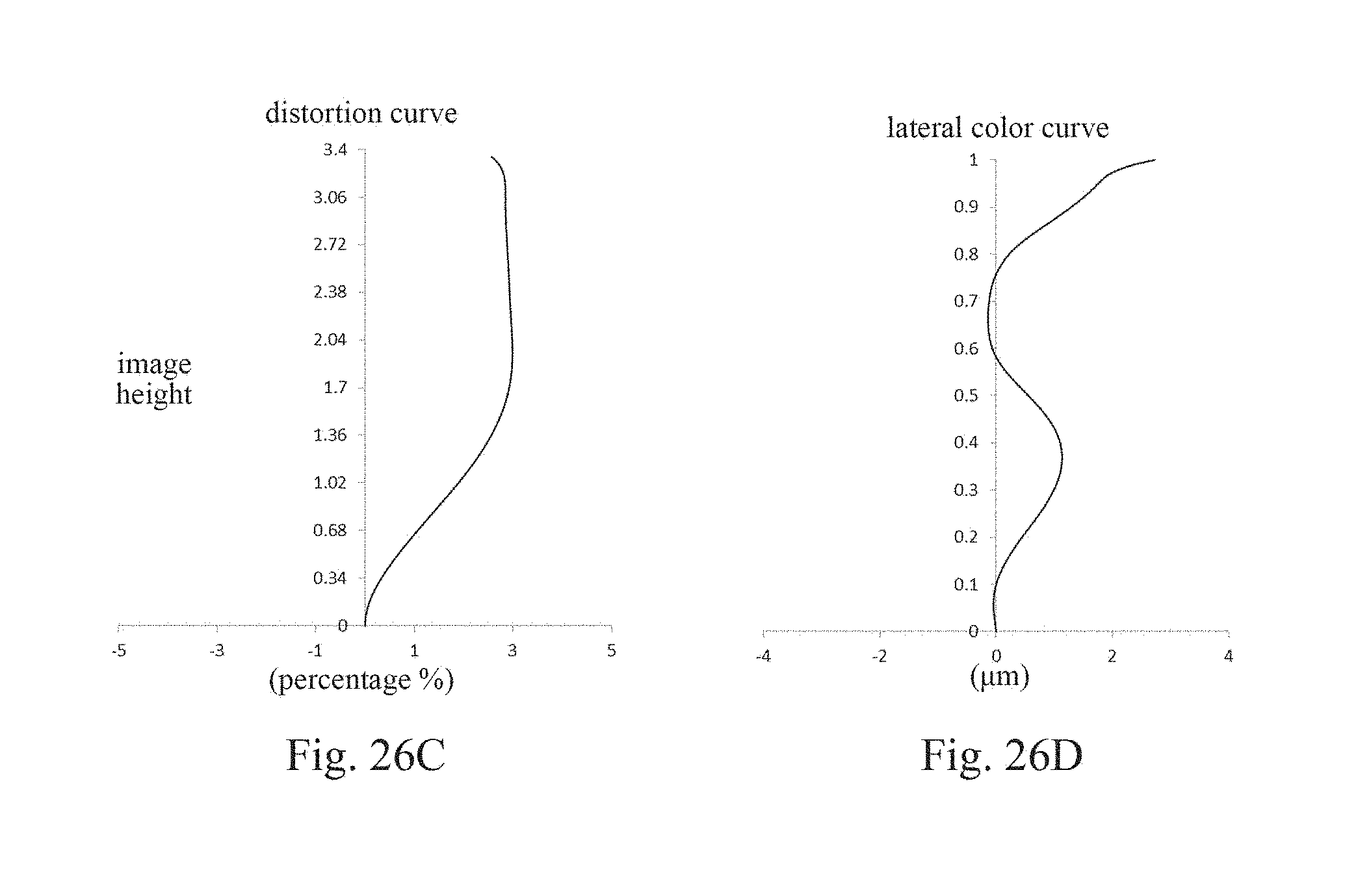

XML
uspto.report is an independent third-party trademark research tool that is not affiliated, endorsed, or sponsored by the United States Patent and Trademark Office (USPTO) or any other governmental organization. The information provided by uspto.report is based on publicly available data at the time of writing and is intended for informational purposes only.
While we strive to provide accurate and up-to-date information, we do not guarantee the accuracy, completeness, reliability, or suitability of the information displayed on this site. The use of this site is at your own risk. Any reliance you place on such information is therefore strictly at your own risk.
All official trademark data, including owner information, should be verified by visiting the official USPTO website at www.uspto.gov. This site is not intended to replace professional legal advice and should not be used as a substitute for consulting with a legal professional who is knowledgeable about trademark law.