Segmented Fuel Distributor
MORENKO; Oleg ; et al.
U.S. patent application number 15/726447 was filed with the patent office on 2019-04-11 for segmented fuel distributor. The applicant listed for this patent is PRATT & WHITNEY CANADA CORP.. Invention is credited to Gavin Rohiteshwar KISUN, Aleksandar KOJOVIC, Oleg MORENKO.
| Application Number | 20190107285 15/726447 |
| Document ID | / |
| Family ID | 65992247 |
| Filed Date | 2019-04-11 |


| United States Patent Application | 20190107285 |
| Kind Code | A1 |
| MORENKO; Oleg ; et al. | April 11, 2019 |
SEGMENTED FUEL DISTRIBUTOR
Abstract
There is provided a segmented fuel distributor for injecting fuel into a combustion chamber. The segmented fuel distributor comprises segments serially interconnected in to provide an annular structure. The segments include a main conduit defining a first axis along which a main fuel flow path extends. The segments having two or more secondary conduits extending from the main conduit and being in fluid flow communication therewith, and fuel injectors fluidly connected to the secondary conduits at remote ends thereof.
| Inventors: | MORENKO; Oleg; (Oakville, CA) ; KOJOVIC; Aleksandar; (Oakville, CA) ; KISUN; Gavin Rohiteshwar; (Mississauga, CA) | ||||||||||
| Applicant: |
|
||||||||||
|---|---|---|---|---|---|---|---|---|---|---|---|
| Family ID: | 65992247 | ||||||||||
| Appl. No.: | 15/726447 | ||||||||||
| Filed: | October 6, 2017 |
| Current U.S. Class: | 1/1 |
| Current CPC Class: | F23R 3/283 20130101; F02C 7/222 20130101; F05D 2240/40 20130101; F23R 3/286 20130101; F23R 3/002 20130101; F23R 3/50 20130101; F23R 3/34 20130101; F05D 2230/53 20130101 |
| International Class: | F23R 3/34 20060101 F23R003/34; F23R 3/28 20060101 F23R003/28 |
Claims
1. A segmented fuel distributor for injecting fuel into a combustion chamber of a gas turbine engine, the segmented fuel distributor comprising a plurality of segments configured to be serially interconnected in fuel flow communication to provide an annular structure, the segmented fuel distributor configured for mounting to an external casing of the gas turbine engine, the segments including a main conduit defining a first axis along which a main fuel flow path extends, the segments having two or more secondary conduits extending from the main conduit and being in fluid flow communication therewith, and fuel injectors fluidly connected to the secondary conduits at remote ends thereof.
2. The segmented fuel distributor of claim 1, wherein the main conduit of each of the segments is fluidly connected to main conduits of circumferentially adjacent segments via transfer tubes, a connection between the transfer tubes and the main conduits being flexible.
3. The segmented fuel distributor of claim 1, wherein each of the secondary conduits defines a second axis disposed at an angle relative to the first axis of the main conduit.
4. The segmented fuel distributor of claim 3, wherein the angle between the second axis and the main conduit is from 15.degree. to 90.degree..
5. The segmented fuel distributor of claim 1, wherein the main conduit and the secondary conduits are integrally formed.
6. The segmented fuel distributor of claim 1, wherein the segments have three of the secondary conduits.
7. The segmented fuel distributor of claim 1, wherein the secondary conduits extend away from each other from the first axis toward the remote ends.
8. The segmented fuel distributor of claim 1, further comprising fuel injector receiving members each affixed to a respective one of the remote ends of the secondary conduits, the fuel injectors fluidly connected to the secondary conduits via the fuel injector receiving members.
9. The segmented fuel distributor of claim 8, wherein the fuel injectors are slidingly received within cavities of the fuel injector receiving members.
10. The segmented fuel distributor of claim 8, wherein the fuel injector receiving members define cooling cavities fluidly connected to an environment of the segmented fuel distributor.
11. The segmented fuel distributor of claim 8, wherein fuel cavities are defined between the fuel injectors and the fuel injector receiving members, the fuel cavities fluidly connected to the secondary conduits.
12. A combustor for a gas turbine engine, comprising a casing and a segmented fuel distributor affixed to the casing and configured for injecting fuel into a combustion chamber of the combustor, the segmented fuel distributor comprising a plurality of segments serially interconnected in fuel flow communication, the segments including a main conduit defining a first axis along which a main fuel flow path extends, the segments having two or more secondary conduits extending from the main conduit and being in fluid flow communication therewith, and fuel injectors fluidly connected to the secondary conduits at remote ends thereof.
13. The combustor of claim 12, wherein the main conduit of each of the segments is fluidly connected to main conduits of circumferentially adjacent segments via transfer tubes, a connection between the transfer tubes and the main conduits being flexible.
14. The combustor of claim 12, wherein each of the secondary conduits defines a second axis disposed at an angle relative to the first axis of the main conduit.
15. The combustor of claim 14, wherein the angle between the second axis and the main conduit is from 15.degree. to 90.degree..
16. The combustor of claim 12, wherein the secondary conduits extend away from each other from the first axis toward the remote ends thereof.
17. The combustor of claim 12, further comprising fuel injector receiving members each affixed to a respective one of the remote ends of the secondary conduits, the fuel injectors fluidly connected the secondary conduits via the fuel injector receiving members.
18. The combustor of claim 12, wherein the casing defines apertures for receiving the fuel injectors therethrough, and wherein the casing defines cylindrical protrusions each disposed around a respective one of the apertures, fuel injector receiving members affixed to the remote ends of the secondary conduits being each received within a respective one of the cylindrical protrusions.
19. A method of assembling a combustor of a gas turbine engine, comprising: disposing fuel distribution segments circumferentially around a central axis of the combustor, the fuel distribution segments having two or more fuel injectors; fluidly connecting the fuel distribution segments with two respectively adjacent ones of the fuel distribution segments to form a segmented fuel distributor; and securing the segmented fuel distributor to a casing of the combustor.
20. The method of claim 19, wherein fluidly connecting the fuel distribution segments comprises fluidly connecting the fuel distribution segments with the two respectively adjacent ones of the fuel distribution segments with transfer tubes, a connection between the transfer tubes and the fuel distribution segments being flexible.
Description
TECHNICAL FIELD
[0001] The application relates generally to gas turbine engines and, more particularly, to systems and methods for injecting fuel in combustors of such engines.
BACKGROUND
[0002] Existing fuel manifolds for gas turbine engines include internal fuel manifolds and external fuel manifolds. While internal fuel manifolds are advantageous in a number of respects (e.g. weight, cost, etc.), they are not as easily removed and/or accessible for maintenance purposes as their more traditionally-used external counterparts. For example, a gas turbine engine with an internal fuel manifold must be split apart in order to access the fuel manifold for service and/or replacement. Consequently, such operations cannot be done in the field and involve more time, cost and engine downtime.
SUMMARY
[0003] In one aspect, there is provided a segmented fuel distributor for injecting fuel into a combustion chamber of a gas turbine engine, the segmented fuel distributor comprising a plurality of segments serially interconnected in fuel flow communication to provide an annular structure, the segmented fuel distributor configured for mounting to an external casing of the gas turbine engine, the segments including a main conduit defining a first axis along which a main fuel flow path extends, the segments having two or more secondary conduits extending from the main conduit and being in fluid flow communication therewith, and fuel injectors fluidly connected to the secondary conduits at remote ends thereof.
[0004] In another aspect, there is provided a combustor for a gas turbine engine, comprising a casing and a segmented fuel distributor affixed to the casing and configured for injecting fuel into a combustion chamber of the combustor, the segmented fuel distributor comprising a plurality of segments serially interconnected in fuel flow communication, the segments including a main conduit defining a first axis along which a main fuel flow path extends, the segments having two or more secondary conduits extending from the main conduit and being in fluid flow communication therewith, and fuel injectors fluidly connected to the secondary conduits at remote ends thereof.
[0005] In yet another aspect, there is provided a method of assembling a combustor of a gas turbine engine, comprising: disposing fuel distribution segments circumferentially around a central axis of the combustor, the fuel distribution segments having two or more fuel injectors; fluidly connecting the fuel distribution segments with two respectively adjacent ones of the fuel distribution segments to form a segmented fuel distributor; and securing the segmented fuel distributor to a casing of the combustor.
BRIEF DESCRIPTION OF THE DRAWINGS
[0006] Reference is now made to the accompanying figures in which:
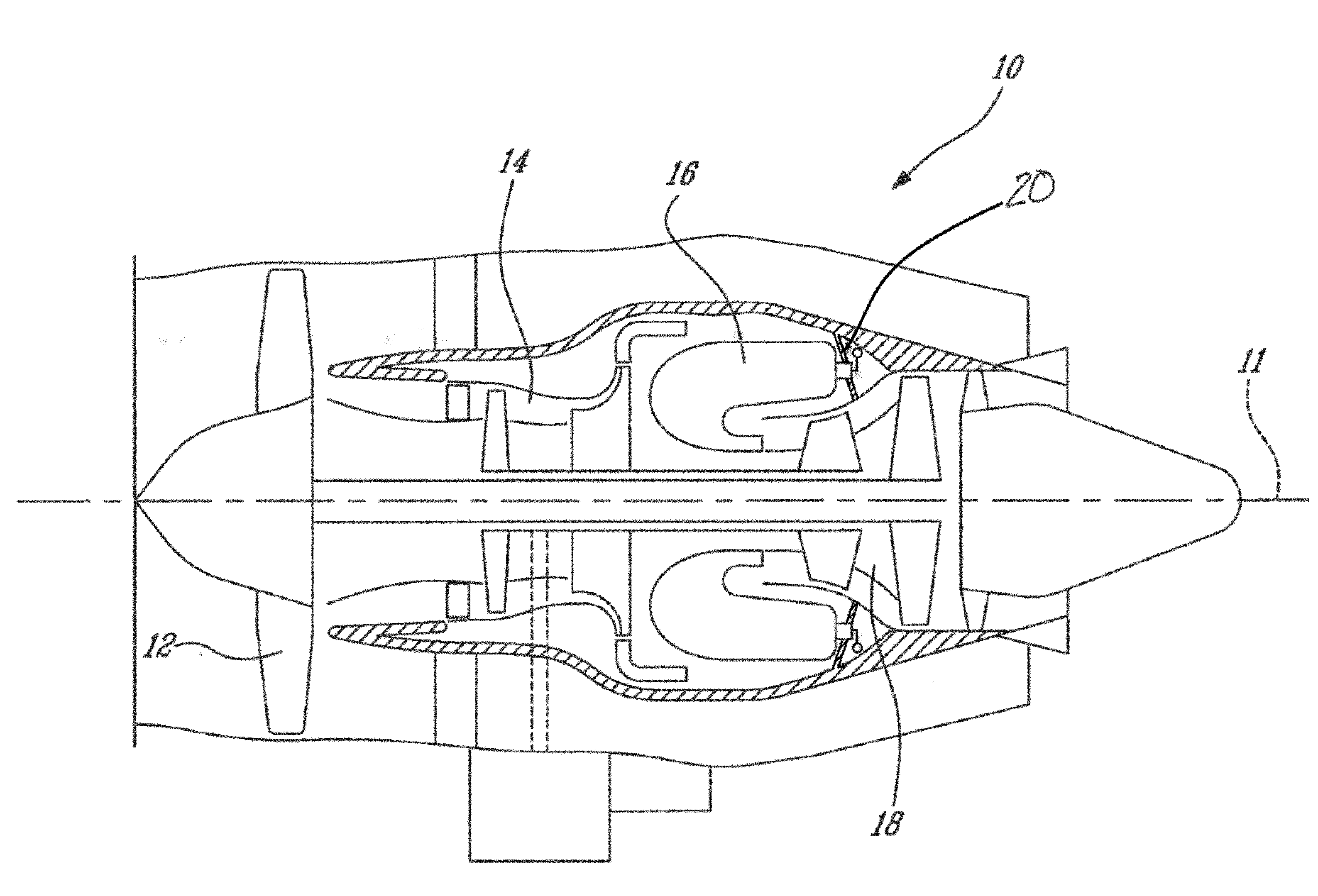
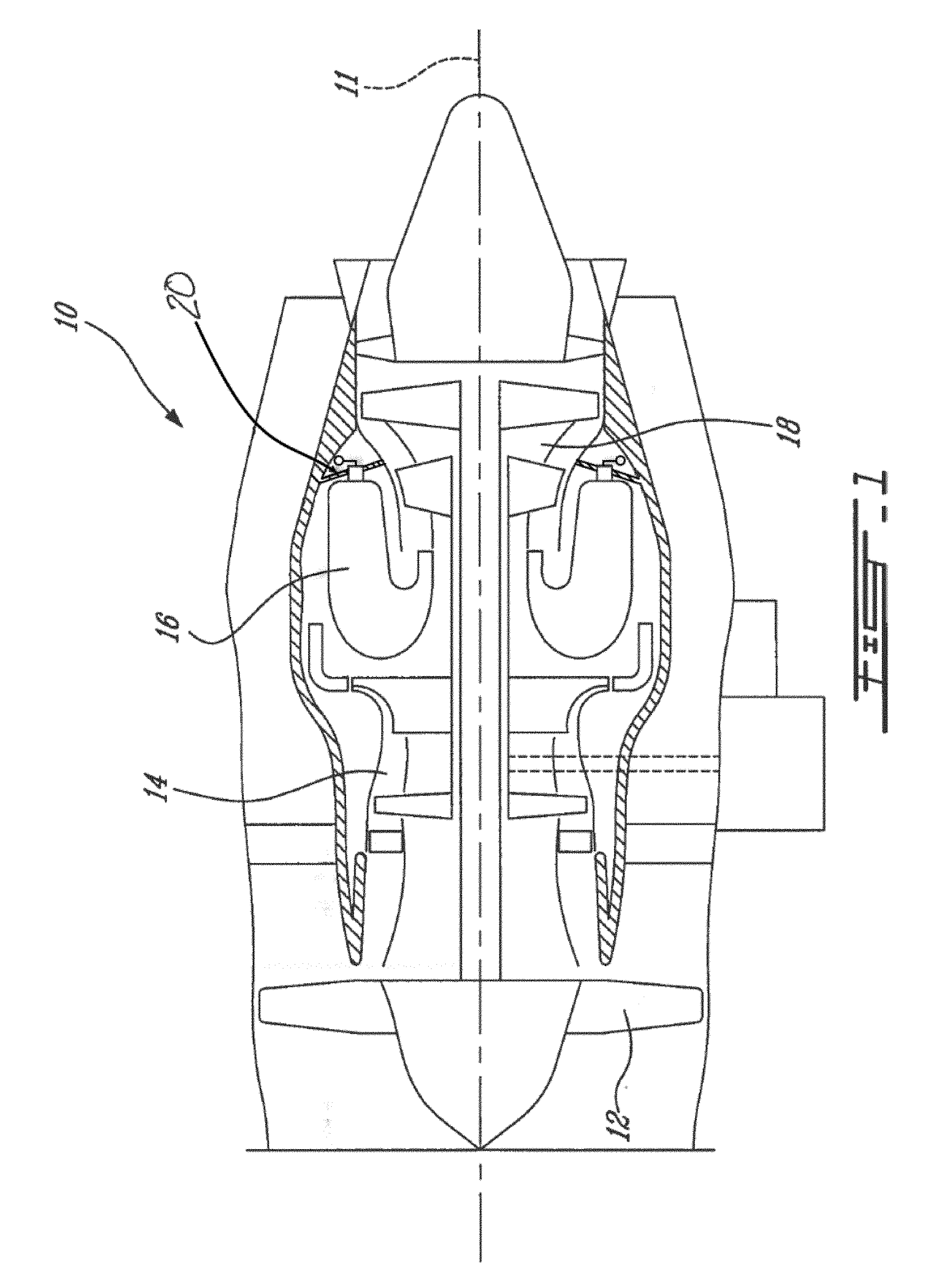
[0007] FIG. 1 is a schematic cross-sectional view of a gas turbine engine;
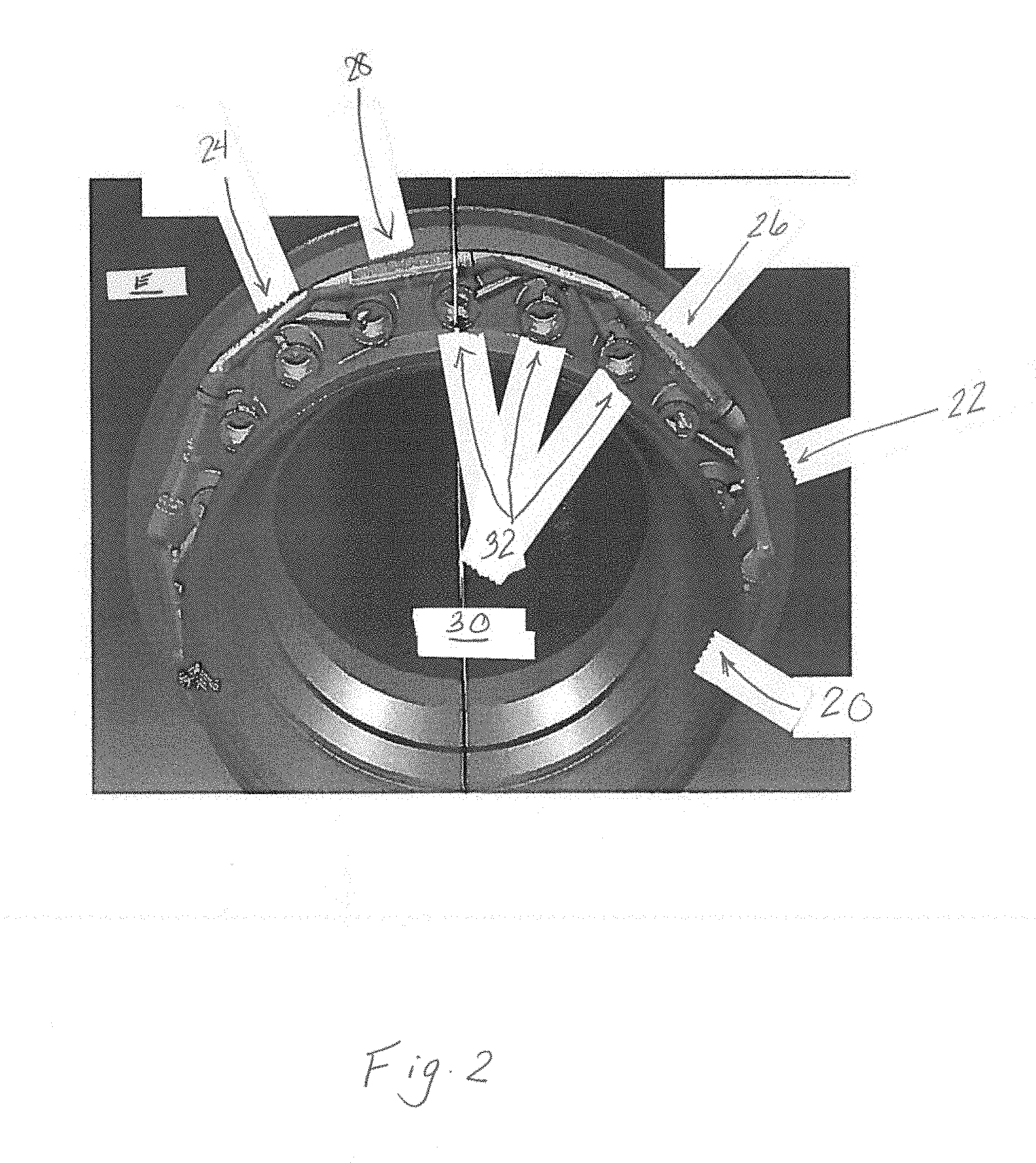
[0008] FIG. 2 is a schematic tridimensional view of a segmented fuel distributor in accordance with one embodiment;
[0009] FIG. 3 is a schematic front view of a fuel carrying segment of the segmented fuel distributor of FIG. 2;
[0010] FIG. 3a is a schematic top view of a segmented fuel distributor comprising fuel carrying segments in accordance with another embodiment;
[0011] FIG. 4 is a schematic cross-sectional view of a portion of the segmented fuel distributor of FIG. 2;
[0012] FIG. 5 is a schematic tridimensional cross-sectional view of a portion of the segmented fuel distributor of FIG. 2;
[0013] FIG. 6 is a schematic tridimensional view of the segmented fuel distributor of FIG. 3a; and
[0014] FIG. 7 is a schematic top cross-sectional view of the segmented fuel distributor of FIG. 6.
DETAILED DESCRIPTION
[0015] FIG. 1 illustrates a gas turbine engine 10 of a type preferably provided for use in subsonic flight, generally comprising in serial flow communication a fan 12 through which ambient air is propelled, a compressor section 14 for pressurizing the air, a combustor 16 in which the compressed air is mixed with fuel and ignited for generating an annular stream of hot combustion gases, and a turbine section 18 for extracting energy from the combustion gases. The compressor section 14, the fan 12, and the turbine section 18 rotate about a central axis 11 of the gas turbine engine 10. In the embodiment shown, the combustor 16 is surrounded by a casing 20 disposed around the central axis 11.
[0016] Referring now to FIG. 2, a portion of the casing 20 and a segmented fuel distributor 22 affixed thereto are shown. The segmented fuel distributor 22 comprises individual fuel carrying segments 24 serially interconnected in fuel flow communication to form an annular structure 26. In the embodiment shown, the individual fuel carrying segments 24 are interconnected with each other with transfer tube assemblies 28. The transfer tube assemblies 28 are configured to allow a flexibility of the segmented fuel distributor 22. A combustion chamber 30 is located radially inward to the casing 20 relative to the central axis 11. Using such transfer tube assemblies 28 might offer certain advantages. In a particular embodiment, the segmented fuel distributer 22 allows for the reduction of weight, components count, installation and service time, possible leak locations, and allows for movement resulting from radial thermal growth. In the embodiment shown, each of the fuel carrying segments 24 acts as a single fuel nozzle having several fuel injection points 32. In one particular embodiment, the fuel carrying segments 24 are made of AMS 5401/INCONEL 625 or other suitable metal.
[0017] Referring now to FIG. 3, one of the individual fuel carrying segments 24 is shown. In the embodiment shown, the fuel carrying segment 24 includes a main conduit 34 extending along a longitudinal axis L along which a primary fuel flow path 36 extends. The fuel carrying segment 24 further includes two or more secondary conduits 38, which may also be referred to as stems, extending away from the main conduit 34 and which each define a secondary fuel flow path. In the depicted embodiment, the fuel carrying segment 24 includes three secondary conduits 38, however it is to be understood that in alternate embodiments there may be only two secondary conduits 38 or there may be more than three secondary conduits 38. In one particular embodiment, the main conduit 34 and the secondary conduits 38 are integrally formed with each other to define a monolithic component. In the depicted embodiment, the secondary conduits 38 are disposed at respective angles .alpha. relative to the main conduit 34 along respective longitudinal axes L'. Secondary fuel flow paths 40 extend through the secondary conduits 38 and are fluidly connected with the main flow path 36 of the main conduit 34. The fuel carrying segment 24 may comprise from two to five, or more, secondary conduits 38. The segmented fuel distributor 22 may comprise simultaneously individual fuel carrying segments 24 having different numbers of secondary conduits 38. The angles between the longitudinal axes L and L' may range from 15.degree. to 90.degree.. The secondary conduits 38 extend away from each other from the longitudinal axis toward remote ends 38a of the secondary conduits 38 relative to a radial distance from the longitudinal axis L. In other words, an axial distance between two of the secondary conduits 38 relative to the longitudinal axis L increases with a radial distance from said longitudinal axis L.
[0018] The main conduit 34 defines two opposed ends 42 and 44 spaced apart from each other along the longitudinal axis L. The two opposed ends 42 and 44 circumscribe openings 46 for receiving a fuel flow to be injected into the combustion chamber 30. In the embodiment shown, the two opposed ends 42, 44 of the main conduit 34 are configured to be fluidly connected with circumferentially adjacent ones of the individual fuel carrying segments 24 via the transfer tube assemblies 28. For that purpose, the fuel carrying segment 24 defines coupling portions 34a adjacent the opposed ends 42, 44 and formed integrally with the main conduit 34.
[0019] The coupling portions 34a are configured for being sealingly connected to the transfer tube assemblies 28. In the embodiment shown, a diameter of the coupling portions 34a is greater than a diameter of the main conduit 34. Each of the coupling portions 34a defines a first annular groove 34b. One of the coupling portions 34a defines a second annular groove 34c of a depth less than that of the other annular grooves 34b and disposed beyond the first annular groove 34b relative to a distance from end 42. In a particular embodiment, the second annular groove 34c is configured for receiving external snap ring or circlip 45 (FIG. 3a) to limit movement of an outer sleeve 68 (FIG. 5). In the embodiment shown, the first annular grooves 34b are configured for receiving O-rings (not shown) for creating a sealing engagement between the coupling portions 34a and the outer sleeve 68. The outer sleeve 68 may then be able to contain a fuel leak. The leaked fuel may be able to drain through drain passages 34e (FIG. 5) defined in the fuel carrying segments 24.
[0020] The fuel carrying segment 24 further includes fuel injector receiving members 50 disposed at the remote, or distal ends 38a of the secondary conduits 38. The fuel carrying segment 24 further includes fuel injectors 52 (FIGS. 4-5) configured for being received by the fuel injector receiving members 50. The assembly of the fuel injectors 52 within the fuel injector receiving members 50 is described herein below.
[0021] In the embodiment shown, the main conduit 34, the secondary conduits 38, and the fuel injector receiving members 50 are integrally formed by suitable manufacturing processes. In the embodiment shown, the fuel carrying segment 24 is integrally formed and fuel passages are formed by manufacturing along the longitudinal axes L and L' of the main and secondary conduits 34 and 38. Manufactured holes 54 are shown for illustration purposes. It is understood that the manufactured holes 54 are suitably clogged to preclude fluid flow communication between the main and secondary flow paths 36 and 40 and an environment E (FIG. 2) of the segmented fuel distributor 22. The fuel carrying segments 24 may be manufactured using metal injection molding (MIM) or additive manufacturing (AM), or other technologies to create complex shapes which might be optimized for weight. In a particular embodiment, the MIM/AM manufacturing is unable to create the fuel passages within the conduits. Said passages may then be manufactured and plug welded at any location where they interface with the environment E. As discussed below, the shape of the fuel carrying segments 24 might improve cooling with ambient air.
[0022] Referring now to FIG. 3A, another embodiment of a fuel carrying segment 24' is illustrated. For the sake of clarity, only the elements that are different than the fuel carrying segment 24 of FIG. 3 are described herein below. In the embodiment shown, the secondary conduits 38' of the fuel carrying segment 24' have an L-shape and extend from the main conduit 34'. An angle .beta. between the main conduit 34' and the secondary conduits 38' may, in one particular embodiment, range from about 5 degrees to about 175 degrees. The secondary conduits 38' each define an angle .theta. such that the secondary conduits 38' curve radially inwardly to reach the fuel injector receiving members 50. In one particular embodiment, the angle .theta. may range from about 60 degrees to about 130 degrees, and an angle between said members 50 and the secondary conduits 38' may be about 90 degrees. However, it is to be understood that other configurations and other ranges for both angle .beta. and angle .theta. can also be used, and will depend upon the specific configuration required, engine architecture, design requirements and parameters, etc.
[0023] Referring now also to FIG. 4, each of the fuel injector receiving members 50 has a cylindrical shape extending perpendicularly to a respective one of the secondary conduits 38. In the embodiment shown, each of the fuel injector receiving members 50 defines two cavities 50a and 50b separated by a wall 50c. The two cavities 50a and 50b overlap each other along a given length relative to a central axis L'' of the fuel injector receiving member 50. In the embodiment shown, the two cavities 50a and 50b decrease in height, or diameter, toward a center of the fuel injector receiving member 50 relative to its central axis L''.
[0024] One of the two cavities 50b is shaped for slidingly and sealingly receiving one of the fuel injectors 52 therein. In the embodiment shown, the other of the two cavities 50a faces away from the casing 20 and is also referred to as a first cooling cavity 50a configured for receiving air from the environment E of the segmented fuel distributor 22. The air circulating in the first cooling cavity 50a might reduce a temperature of the fuel carrying segment 24. In the depicted embodiment, the fuel injector receiving member 50 further defines a second cooling cavity 50d configured for receiving a flow of air from the environment E and is fluidly connected with the first cooling cavity 50a.
[0025] The secondary flow paths 40 extend through the fuel injector receiving members 50 such that the fuel injectors 52 are in fluid flow communication with the one of the two cavities 50b. Fuel cavities 56 are defined between the fuel injectors 52 and cylindrical walls of the fuel injector receiving members 50. The fuel cavities 56 are fluidly connected with the one of the two cavities 50b and with the main conduit 34 via the secondary conduits 38. Stated otherwise, the fuel cavities 56 are fluidly connected with the main flow path 36 via the secondary flow paths 40.
[0026] Still referring to FIG. 4, the fuel injectors 52 define outlets 58 fluidly connected to the main conduit 34 via the secondary conduits 38, along the main and secondary flow paths 36 and 40, and via the fuel cavities 56, for injecting fuel in the combustion chamber 30. Any suitable fuel injector may be used. The fuel injectors 52 may be integrally formed with the fuel carrying segments 24 or separated as shown.
[0027] Referring now also to FIG. 5, apertures 20a are defined through the casing 20 for allowing the fuel injectors 52 to extend therethrough. Each of the apertures 20a is surrounded by a respective one of cylindrical protrusions 20b, also referred to as slotted bosses, that are hollow for slidingly receiving the fuel injector receiving members 50 therein. In the embodiment shown, a diameter of the apertures 20a is less than that of an inner diameter of the cylindrical protrusions 20b to define annular tabs 20c. The fuel injector receiving members 50, once disposed within the cylindrical protrusions 20b may abut against the annular tab 20c.
[0028] The cylindrical protrusions 20b are hollow and are each shaped for receiving therein a respective one of the fuel injector receiving members 50 of the fuel carrying segments 24. Each of the cylindrical protrusions 50 defines a slot 20d for allowing the secondary conduits 38 to extend through the cylindrical protrusions 20b. In the embodiment shown, inner surfaces of the cylindrical protrusions 20b are threaded for receiving nuts 64 to be screwed therein to limit movements of the fuel injector receiving members 50 when they are received within the cylindrical protrusions 20b. In the depicted embodiment, the nuts 64 are hollow for allowing fluid flow communication between the first cooling cavity 50a and the environment E.
[0029] In the embodiment shown, gaskets 62 are disposed between the fuel injector receiving members 50 and the cylindrical protrusions 20b for providing a sealing engagement therebetween. In the depicted embodiment, the gaskets 62 are annular and disposed adjacent to the annular tabs 20c to be sandwiched between said tabs 20c and the fuel injector receiving members 50. More specifically, air that has been compressed through its passage in the compressor section 14 is injected in the combustor chamber 30 for being mixed with fuel. The gaskets 62 are configured to preclude the compressed air to escape the combustion chamber 30 via an intersection between the cylindrical protrusions 20b and the fuel injector receiving members 50.
[0030] Still referring to FIG. 5, the transfer tube assemblies 28 are illustrated. The transfer tube assemblies 28 each include two transfer tubes 66 that are disposed within an outer sleeve 68 configured for maintaining a position of the transfer tubes 66 therein. In the embodiment shown, the main conduits 34 define two inlets 34d each receiving a respective one of the transfer tubes 66. It is understood that the transfer tube assemblies 28 may comprise less, or more, than two of the transfer tubes 66. Similarly, the main conduits 34 may comprise less, or more, than two of the inlets 34d. In the embodiment shown, the transfer tubes 66 are made of AMS 5648/SS 316 stainless steel or other suitable metal.
[0031] In the embodiment shown, the secondary conduits 38 define each two fuel passages (not shown) each fluidly connected to a respective one of the two transfer tubes 66. Therefore, the main flow path 36 defines two main sub-flow paths 36a and 36b and each of the secondary conduits 38 defines two secondary sub-flow paths 40a and 40b. The two main sub-flow paths 36a and 36b are in fluid flow communication with a respective one of the two secondary sub-flow paths 40a and 40b. In the embodiment shown, the fuel injectors 52 have each two of the fuel outlets 58 each fluidly connected to a respective one of the two secondary sub-flow paths 40a and 40b.
[0032] A connection C between the transfer tube assemblies 28 and the segments 24 offers a flexibility that allows some displacement of the segments 24 relative to the assemblies 28. Such displacement might be the result of thermal expansion during use. More specifically, the flexibility is provided by the interaction between the transfer tubes 66 and the inlets 34d of the main conduit 34. In the embodiment shown, the connection C is flexible and allows variations of about .+-.3 degrees between a longitudinal axis of each of the transfer tubes 66 and the main conduit 34 of the segments 24.
[0033] Referring now to FIGS. 3a, 6, and 7, the outer sleeve 68 has a cylindrical shape and defines two ends 68a and 68b that have a diameter greater than that of a central section 68c disposed between the two ends 68a, 68b. In the embodiment shown, two ends 68a, 68b are each configured for receiving therein the coupling portions 34a' of the segments 24'. O-rings (not shown) may be disposed within the annular grooves 34b' to create a sealing engagement between the coupling portions 34a and the outer sleeve ends 68a, 68b.
[0034] The outer sleeve 68 further includes two tabs 68d each defining an aperture. In the embodiment shown, the two tabs are diametrically opposed relative to a longitudinal axis of the outer sleeve 68. The tabs 68d are configured for manipulating the outer sleeve 68, and thus any transfer tube assemblies 28 mounted thereto, in order to position and move the transfer tube assemblies 28 and/or the outer sleeve 68 into or out of a desired position. Thus, the tabs 68d can be used to push or pull and simultaneously engage or disengage the transfer tubes and the outer sleeve with a corresponding fuel carrying segment 24 or fuel nozzle.
[0035] Referring more particularly to FIG. 7, the outer sleeve 68 encloses a support member 68e defining two apertures for receiving therein, and for supporting, the transfer tubes 66. In the embodiment shown, the support member 68e limits radial and/or axial movements of the tubes 66 relative to the outer sleeve 68. In the embodiment shown, each of the two transfer tubes 66 have two sections 66a, 66b that are jointed together at a location of the support member 68e. Each of the two sections 66a, 66b defines abutment portions 66c configured for abutting against the support member 68e. The abutment portions 66c are configured to limit axial movement of each of the two sections 66a, 66b toward each other.
[0036] Referring to FIGS. 1 to 7, to assemble the combustor 16 of the gas turbine engine 10 the fuel distribution segments 24 are first circumferentially distributed around the central axis of the combustor 11. Then, the fuel distribution segments 24 are each fluidly connected with two respectively adjacent ones of the fuel distribution segments 24 with the transfer tubes 66 of the transfer tube assemblies 28 to form the segmented fuel distributor 22. Then, the segmented fuel distributor 22 is secured to the casing 20.
[0037] More specifically, the fuel injector receiving members 50 are each secured to the casing 20, within a respective one of the cylindrical protrusions 20b, with the nuts 64 screwed in the cylindrical protrusions 20b.
[0038] Referring more particularly to FIG. 5, the two transfer tubes 66 are coupled with the inlets 34d defined by the main conduits 34 of the fuel carrying segments 24. Therefore, the fuel injectors 52 are each fluidly connected to both of the transfer tubes 66 via the connections C.
[0039] In the depicted embodiment, the fuel injector receiving members 50 are pushed in a sealing engagement against the gaskets 62 that abut against the annular tabs 20c defined by the casing 20. The nut 64 may be used for that purpose.
[0040] In the embodiment shown, the fuel injector receiving members 50, which are disposed at the remote ends 38a (FIG. 3) of the secondary conduits 38 are disposed in the cylindrical protrusions 20b extending from the casing 20. In the depicted embodiment, the fuel injectors 52 are fluidly connected to the fuel injector receiving members 50 of the fuel distribution segments 24 during the assembly.
[0041] Referring more particularly to FIG. 6, following installation of the fuel injector receiving members 50 within the cylindrical protrusions 20b, the transfer tube assemblies 28 are each slid and locked into position. More specifically, the outer sleeve ends 68a are slid over first coupling portions 34a of the main conduit 34. Then, the transfer tube assemblies 28 are each slid toward second coupling portions 34a of an adjacent one of the segments 24. Then, the circlips 45 (FIG. 3a) are each disposed within the second annular grooves 34c (FIG. 3) of the first coupling portions 34a to limit a sliding movement between the outer sleeves 68 and the coupling portions 34a.
[0042] The above description is meant to be exemplary only, and one skilled in the art will recognize that changes may be made to the embodiments described without departing from the scope of the invention disclosed. Still other modifications which fall within the scope of the present invention will be apparent to those skilled in the art, in light of a review of this disclosure, and such modifications are intended to fall within the appended claims.
* * * * *
D00000
D00001
D00002
D00003
D00004
D00005
D00006
D00007
D00008
XML
uspto.report is an independent third-party trademark research tool that is not affiliated, endorsed, or sponsored by the United States Patent and Trademark Office (USPTO) or any other governmental organization. The information provided by uspto.report is based on publicly available data at the time of writing and is intended for informational purposes only.
While we strive to provide accurate and up-to-date information, we do not guarantee the accuracy, completeness, reliability, or suitability of the information displayed on this site. The use of this site is at your own risk. Any reliance you place on such information is therefore strictly at your own risk.
All official trademark data, including owner information, should be verified by visiting the official USPTO website at www.uspto.gov. This site is not intended to replace professional legal advice and should not be used as a substitute for consulting with a legal professional who is knowledgeable about trademark law.