Bit Holder
Buhr; Karsten ; et al.
U.S. patent application number 16/149205 was filed with the patent office on 2019-04-11 for bit holder. The applicant listed for this patent is Wirtgen GmbH. Invention is credited to Karsten Buhr, Andreas Jost, Thomas Lehnert.
| Application Number | 20190106988 16/149205 |
| Document ID | / |
| Family ID | 63708230 |
| Filed Date | 2019-04-11 |


| United States Patent Application | 20190106988 |
| Kind Code | A1 |
| Buhr; Karsten ; et al. | April 11, 2019 |
BIT HOLDER
Abstract
The invention relates to a bit holder for an earth working machine, in particular a road milling machine, having a support body onto which a holding portion having a bit receptacle, and oppositely an insertion projection, are shaped. The holding portion is terminated at the end by a wear surface, and the bit receptacle by a centering receptacle opening in bevel fashion toward the wear surface. A centering height, measured in the direction of the longitudinal center axis, between an end of the centering receptacle and the wear surface or a maximum point of a projection projecting beyond the wear surface, is designed in such a way that the ratio between the inside diameter D.sub.i of the bit receptacle and the centering height is less than 8; and/or that the centering height is greater than an axial play of a round-shank bit installable in the bit holder; and that the support body comprises, on its side facing away from the holding portion, at least two bearing surfaces that are at an angle to one another and form a bearing-surface pair. Reduced wear on the holding portion and a reduced load on the insertion projection, and thus an extension of the service life of the bit holder, are achieved.
| Inventors: | Buhr; Karsten; (Willroth, DE) ; Jost; Andreas; (Konigswinter, DE) ; Lehnert; Thomas; (Oberraden, DE) | ||||||||||
| Applicant: |
|
||||||||||
|---|---|---|---|---|---|---|---|---|---|---|---|
| Family ID: | 63708230 | ||||||||||
| Appl. No.: | 16/149205 | ||||||||||
| Filed: | October 2, 2018 |
| Current U.S. Class: | 1/1 |
| Current CPC Class: | B28D 1/188 20130101; E21C 35/19 20130101; E21C 35/197 20130101; E21C 35/1933 20130101; E21C 35/18 20130101; E21C 35/191 20200501 |
| International Class: | E21C 35/197 20060101 E21C035/197; E21C 35/193 20060101 E21C035/193 |
Foreign Application Data
| Date | Code | Application Number |
|---|---|---|
| Oct 9, 2017 | DE | 102017123368.7 |
Claims
1-11: (canceled)
12: A bit holder for an earth working machine, comprising: a support body including a holding portion and an insertion projection, the holding portion being located on a working side of the support body, and the insertion projection extending from a side of the support body opposite from the holding portion; the holding portion including: a bit receptacle having a longitudinal center axis and an inside diameter; a wear surface defined on an end of the holding portion facing away from the support body, the wear surface surrounding the bit receptacle and being configured for abutment of a round-shank bit or of a support element for a round-shank bit; a centering surface oriented obliquely to the longitudinal center axis of the bit receptacle, the centering surface connecting the bit receptacle and the wear surface and defining a centering receptacle, the centering receptacle having a centering height measured parallel to the longitudinal center axis, the centering height extending between an end of the centering receptacle facing away from the wear surface and a maximum point of projection of the wear surface, a ratio of the inside diameter of the bit receptacle to the centering height being less than 8.0; wherein the support body includes at least one bearing surface on the second side of the support body, the at least one bearing surface extending on both sides of a center plane of the support body including the longitudinal center axis of the bit receptacle.
13: The bit holder of claim 12, wherein the ratio of the inside diameter of the bit receptacle to the centering height is less than 7.5.
14: The bit holder of claim 12, wherein the ratio of the inside diameter of the bit receptacle to the centering height is less than 7.0.
15: The bit holder of claim 12, wherein the ratio of the inside diameter of the bit receptacle to the centering height is less than 6.5.
16: The bit holder of claim 12, wherein the maximum point of projection surrounds the bit receptacle.
17: The bit holder of claim 12, wherein: the wear surface includes a plurality of projections projecting beyond a lowest part of the wear surface by the same or differing heights; and the centering height is defined with reference to one of the projections having a greatest height.
18: The bit holder of claim 12, wherein: the wear surface includes a guidance groove defined in the wear surface and spaced away from and surrounding the centering receptacle.
19: The bit holder of claim 18, wherein: the maximum point of projection is located between the centering receptacle and the guidance groove; and the centering receptacle has a greater depth with respect to another portion of the wear surface adjacent the guidance groove than does the guidance groove.
20: The bit holder of claim 12, wherein a transition between the centering surface and the maximum point of projection is continuous or rounded.
21: The bit holder of claim 12, wherein a height of the maximum point of projection with respect to a lowest part of the wear surface is greater than or equal to 0.3 mm.
22: The bit holder of claim 12, wherein the height of the maximum point of projection with respect to a lowest part of the wear surface is in a range of from 0.3 mm to 2.0 mm.
23: The bit holder of claim 12, wherein the height of the maximum point of projection with respect to a lowest part of the wear surface is in a range of from 0.5 mm to 1.5 mm.
24: The bit holder of claim 12, wherein the inside diameter of the bit receptacle is equal to 20 mm and the centering height is greater than 2.5 mm.
25: The bit holder of claim 12, wherein the inside diameter of the bit receptacle is equal to 22 mm and the centering height is greater than 2.75 mm.
26: The bit holder of claim 12, wherein the inside diameter of the bit receptacle is equal to 25 mm and the centering height is greater than 3.125 mm.
27: The bit holder of claim 12, wherein the inside diameter of the bit receptacle is equal to 42 mm and the centering height is greater than 5.25 mm.
28: The bit holder of claim 12, wherein the maximum point of projection is formed on the wear surface by a material-removing production method selected from the group consisting of turning, sinking and milling.
29: The bit holder of claim 12, wherein the at least one bearing surface comprises a bearing surface pair of two bearing surfaces on opposite sides of the center plane.
30: The bit holder of claim 29, wherein the at least one bearing surface further comprises at least one further bearing surface that is at an angle to the two bearing surfaces of the bearing surface pair.
31: The bit holder of claim 12, wherein the centering height is greater than an axial play of a round-shank bit installed in the bit holder.
Description
BACKGROUND OF THE INVENTION
1. Field of this Invention
[0001] The invention relates to a bit holder for an earth working machine, in particular a road milling machine, having a support body on which is shaped, in the region of a working side, a holding portion into which a bit receptacle for reception of the shank of a round-shank bit is shaped; the holding portion being terminated at its end facing away from the support body by a wear surface, enclosing the bit receptacle, for abutment of the round-shank bit or of a support element; the bit receptacle being transitioned indirectly or directly into the wear surface via a centering surface, oriented obliquely to the longitudinal center axis of the bit receptacle, of a centering receptacle; and an insertion projection, for fastening the bit holder onto a base mount, being shaped onto the support body on the side located oppositely from the holding portion.
2. Description of the Prior Art
[0002] Earth working machines are used to carry out milling tasks on hard substrates, for example on roads. Such machines each comprise a rotating milling drum. Fastened on the milling drum are a plurality of bits that, as a result of the rotation of the milling drum, penetrate into the substrate and remove it. The bits are subjected to considerable wear in this context. It is therefore known to fasten the bits replaceably on a milling drum tube of the milling drum. Base mounts can be mounted for that purpose fixedly, for example by welding, on the milling drum tube. A bit holder can then be detachably fastened on such a base mount. The bit holder comprises a bit receptacle in which a bit can also be detachably installed. Worn bits can thus easily be replaced. If the bit holder is also worn down after several bit changes, it can be detached from the base mount and replaced. It is known to mount the bits in the bit holder rotatably around their longitudinal axis and in axially immobilized fashion. The bits rotate around their longitudinal axes during the milling process, with the result that a bit tip or bit head engaging into the substrate becomes evenly worn over its periphery. In order to absorb axially acting forces, the bit head abuts against the bit holder directly or with interposition of a support element. As a result of the rotation, the bit holder is subjected to increased wear in the region where the bit head or support element rests. In addition to the axial forces, large transverse forces also act on the bit during earth working. These result in uneven erosion of the bit holder in the region where the bit head or support element rests. They also result in large forces at the transition from the bit holder to the base mount. If the bit holder wears unevenly, free rotatability of the bit is then limited and in particular it then tends to jam. If the rotatability of the bit is limited, however, it no longer wears evenly along its periphery in the desired manner. What occurs instead is one-sided wear, which leads to premature tool failure.
[0003] DE 10 2014 104 040 A1 (US 2017/030191) discloses a bit, in particular a round-shank bit, having a bit head and a bit shank. The bit is held with its bit shank in a cylindrical bit receptacle of a holding projection of a bit holder. For that purpose the bit shank is fastened in the bit receptacle, by means of a fastening sleeve, rotatably around its longitudinal center axis but in axially immobilized fashion. The bit head, whose diameter is larger as compared with the bit shank, rests, at the end and surroundingly with respect to the bit receptacle, on a wear surface of the holding projection via a disk-shaped support element. The holding projection is of cylindrical configuration. Oppositely from the bit, the holding projection is connected to a base part of the bit holder. The base part extends transversely with respect to the holding projection. Shaped onto the base part in laterally offset fashion, and located oppositely from the holding projection, is an insertion projection that serves to fasten the bit holder to an above-described base mount of a milling drum. The bit receptacle is embodied as a passthrough orifice that passes through the holding projection.
[0004] The bit receptacle widens toward the bit into a centering receptacle. The surface of the centering receptacle is oriented obliquely to the longitudinal center axis of the bit receptacle. It transitions via a ridge into the wear surface of the holding projection. The ridge projects out beyond the wear surface. That surface of the support element which faces toward the holding projection is embodied complementarily to the end face of the holding projection. The support element rests with a seating surface on the wear surface of the holding projection. Shaped into the support element in the region of the ridge is a surrounding groove that receives the ridge. A centering projection of the support element, projecting beyond the seating surface, engages positively into the centering receptacle of the bit holder. The support element is guided in a radial direction thanks to the engagement of the centering projection into the centering receptacle, and of the ridge into the groove.
[0005] Axial play of the bit in the bit mount is necessary in order to ensure rotatability of the bit around its longitudinal center axis. A larger axial play is provided for larger bits than for smaller bits. If the axial play exceeds the height of the centering receptacle, lateral guidance of the support element by the centering projection is lost. This results in elevated and uneven wear on the bit holder, thereby shortening its service life. This is true especially in the context of the large transverse forces that are transferred from the bit head via the support element to the wear surface of the holding projection and result in uneven abrasion there when the support element is not guided exactly. At the same time, the large transverse forces result in heavy loads on the insertion projection and on the fastening elements with which the insertion projection is held in the base mount. Those forces can result in fatigue breakages at the insertion projection or in wear on or detachment of the fastening elements, and thus in damage to or loss of the bit holder having the bit mounted thereon.
[0006] EP 1 427 913 B1 (U.S. Pat. No. 6,824,225) discloses a subassembly having a rotatable cutting bit and a disk. The disk comprises ribs on its front side facing toward the head of the cutting bit, and recesses on its oppositely located rear side, thereby improving the rotatability of the disk around its center axis. Shaped onto its rear side, surroundingly and adjacently to a central orifice, is a centering projection having a surface oriented obliquely to the center axis. When the bit is installed, the centering projection engages into a bevel mounted at the end on a cylindrical bit receptacle of a bit holder. The disk is thereby laterally guided. The bevel protrudes only slightly beyond the rear side of the disk. As a result of the required axial play of the cutting bit, the centering projection can be shifted out of engagement with the bevel so that its lateral guidance is lost. This results in elevated wear on both the disk and the bit holder, especially when large transverse forces are acting on the bit.
SUMMARY OF THE INVENTION
[0007] The object of the invention is to furnish a bit holder for an earth working machine, in particular a road milling machine, which has a long service life.
[0008] The object of the invention is achieved in that a centering height, measured in the direction of the longitudinal center axis, which extends between an end of the centering receptacle facing away from the wear surface and a maximum point of a projection projecting beyond the wear surface, is designed in such a way that the ratio between the inside diameter of the bit receptacle and the centering height is less than 8; and/or that the centering height is greater than an axial play of a round-shank bit installed in the bit holder; and that the support body comprises one or several bearing surfaces on its side facing away from the holding portion, the one bearing surface extending on both sides of a center plane that receives the center axis and extends in the advance direction, or that at least one bearing surface respectively extends on both sides of that center plane.
[0009] The centering receptacle serves to receive and guide a centering projection of a support element that can be arranged between a round-shank bit and the holding portion of the bit holder, or a centering projection shaped directly onto the round-shank bit if the latter abuts against the holding portion with no interposed support element. The centering projection is embodied complementarily in terms of shape with respect to the centering receptacle, and projects beyond a surface (seating surface or resting surface), facing toward the bit holder, of the support element or of the bit head. The centering projection is thus in engagement with the centering receptacle, and the support element or the round-shank bit is thereby radially guided. If a projection is shaped on in the region of the wear surface of the bit holder, that projection engages into a corresponding recess in the seating surface of the support element or in the resting surface of the bit head. Additional lateral guidance of the support element or of the bit head is thereby achieved. The result of the feature that the ratio between the inside diameter D.sub.i of the bit receptacle and the centering height is less than 8 is to ensure sufficient immobilization, or reduction of a lateral motion, of the support element or of the round-shank bit with respect to the bit holder. The centering height can be selected to be greater than the maximum axial play of the round-shank bit which is to be expected over the life expectancy of the round-shank bit. For large round-shank bits having correspondingly large bit shanks, the axial play is greater than for comparatively small round-shank bits. This is taken into account by specifying the numerical ratio between the inside diameter D.sub.i of the bit receptacle and the centering height. Good lateral guidance of the support element or of the round-shank bit is thus ensured, for all bit sizes being used, when a bit is withdrawn maximally out of the bit receptacle within the axial play. Longitudinal wear on the holding portion of the bit holder can be minimized thanks to the small lateral motion of the support element and of the round-shank bit. This also applies in particular in a context of large transverse forces acting on the round-shank bit, which are transferred onto the wear surface of the bit holder via the support element or directly from the bit head. With insufficient lateral guidance of the support element or round-shank bit, such uneven loads on the wear surface cause asymmetrical and thus more intense wear on that surface. Wear on the bit holder, in particular when large transverse forces occur, is thus significantly reduced because of the embodiment according to the present invention of the centering receptacle and, if applicable, of the projection as a function of the diameter of the bit receptacle. As a result thereof, the bit holder needs to be replaced significantly less often.
[0010] As already stated earlier, large transverse forces also result in heavy loading of the insertion projection and of the fastening elements with which the insertion projection of the bit holder is held in the base mount. In order to adapt the service life of the fastening system for the bit holder to the extended service life of the holding portion, provision is made according to the present invention that the support body comprises, on its side facing away from the holding portion, at least two bearing surfaces (first or second bearing surfaces) constituting a bearing-surface pair, which are at an angle to one another. When the bit holder is installed, these bearing surfaces abut against corresponding support surfaces of the base mount on which the bit holder is fastened with its insertion projection. Forces transferred to the round-shank bit and thus to the bit holder are discharged to the base mount both via the insertion projection and via the bearing surfaces. Stresses on the insertion projection and its fastening elements are thereby reduced, with the result that premature wear on or breakage of the insertion projection and the fastening elements can be avoided. In particular, large transverse forces can be transferred to the base mount by the bearing surfaces at an angle to one another. The bearing surfaces are preferably oriented in such a way that the forces to be transferred from the bearing surfaces to the support surfaces are oriented substantially in the direction of the surface normal line of one of the bearing surfaces or support surfaces. Because the bearing surfaces are at an angle to one another and constitute a bearing-surface pair, the support body and thus the bit holder can preferably be embodied symmetrically. The bit holder can thus be used at all positions on the milling drum which, for example, are oriented in mirror-image fashion with respect to one another on the opposite sides of the milling drum.
[0011] The centering receptacle, in interaction with the centering projection, also results in a labyrinth-like seal. Wear on the bit is thereby reduced. The sealing effect can be further improved by projections that are arranged on the wear surface and engage into recesses corresponding thereto.
[0012] According to a preferred variant embodiment of the invention, provision can be made that the ratio between the inside diameter D.sub.i of the bit receptacle and the centering height is less than 7.5, preferably less than 7.0, particularly preferably less than 6.5. With a ratio of less than 7.5, good lateral guidance is achieved even when transverse forces act directly on the support element or on the round-shank bit, for example as a result of impacts of removed material. A ratio of less than 7.0 again improves lateral guidance, so that even the simultaneous action of axially oriented forces unevenly distributed over the support element and radially acting transverse forces does not result in a tumbling motion of the support element with consequently severe wear. With a ratio of less than 6.5, sufficient lateral guidance is achieved even toward the end of the service life of the support element and of the round-shank bit, when the axial play of the round-shank bit may have become impermissibly large due to the wear that has already occurred.
[0013] Radially acting guidance of the support element and/or of the round-shank bit, along with good rotatability of the support element and/or of the bit, can be achieved by the fact that the projection is arranged surroundingly with respect to the bit receptacle.
[0014] Lateral guidance of the support element can furthermore be improved by the fact that several projections of the same or different height can be shaped onto the wear surface of the holding portion; and that the ratio between the inside diameter D.sub.i of the bit receptacle and the centering height with respect to one of the projections, preferably the ratio between the inside diameter D.sub.i of the bit receptacle and the greatest centering height determined with respect to a projection, is less than 8.
[0015] With several projections that are arranged radially next to one another and engage into recesses corresponding thereto, the projected area of the wear surface in an axial direction is maintained but the contact surface between the bit holder and the support element or the round-shank bit in a radial direction is enlarged. Greater transverse forces can be absorbed as a result. At the same time, the contact area between the bit holder and the support element or round-shank bit is enlarged, which has a positive effect on wear behavior. The sealing effect with regard to penetration of removed material is furthermore considerably improved thanks to the juxtaposition of the projections and the recesses that receive the projections. As a result of the ratio of less than 8 between the inside diameter D.sub.i of the bit receptacle of the bit holder and the centering height, sufficient radial guidance of the support element and of the round-shank bit is achieved even when a support element or round-shank bit is raised maximally off the wear surface in the context of the axial play.
[0016] A further improvement in lateral guidance can be achieved in that a guidance groove is shaped into the adjacent wear surface, spaced away from and surroundingly with respect to the centering receptacle. The guidance groove makes it possible for a guidance land, shaped onto the support element or round-shank bit, to engage thereinto. The rotatability of the support element or round-shank bit is thereby improved, resulting in decreased longitudinal wear on the holding portion of the bit holder.
[0017] Good rotatability of the support element or round-shank bit can be achieved by the fact that the projection is embodied between the centering receptacle and the guidance groove; and that the centering receptacle has, with respect to the adjacent wear surface, a greater depth than the guidance groove. Three-point radial guidance of the support element or of the round-shank bit on the bit holder is thereby achieved, namely in the region of the centering receptacle, at the projection, and at the guidance groove.
[0018] The rotatability of the support element or of the round-shank bit can be further improved by the fact that transitions between the centering surface, the wear surface, the projection, and/or the guidance groove proceed in continuous or rounded fashion. Sharp edges and rotation-blocking edges are thereby avoided.
[0019] Good lateral guidance of the support element or of the round-shank bit can result from the fact that the height of the projection with respect to the wear surface is greater than or equal to 0.3 mm, preferably between 0.3 mm and 2 mm, particularly preferably between 0.5 mm and 1.5 mm. A sufficient improvement in lateral guidance of the support element or round-shank bit cannot be achieved with a projection smaller than 0.3 mm. Good lateral guidance of the support element or round-shank bit can be attained with a projection in the range between 0.3 mm and 2 mm. Projections having a height of between 0.5 mm and 1.5 result in particular in good rotatability of the support element or the round-shank bit.
[0020] For usual bit sizes and associated bit holders, provision can be made that the inside diameter D.sub.i is equal to 20 mm and the centering height is greater than 2.5 mm; and/or that the inside diameter D.sub.i is equal to 22 mm and the centering height is greater than 2.75 mm; and/or that the inside diameter D.sub.i is equal to 25 mm and the centering height is greater than 3.125 mm; and/or that the inside diameter D.sub.i is equal to 42 mm and the centering height is greater than 5.25 mm. For smaller bits, for example for precision milling, bit receptacles having an inside diameter D.sub.i of 20 mm or 22 mm and a centering height respectively of at least 2.5 mm or 2.75 mm are suitable. For medium-sized bits, bit receptacles having an inside diameter D.sub.i of 25 mm and a centering height of 3.125 mm are suitable. For large bits and associated bit holders, bit receptacles having an inside diameter D.sub.i of 42 mm with a centering height of at least 5.25 mm can be used. With a ratio of less than 8 between the inside diameters D.sub.i of the bit receptacles and the respective centering height, suitable centering projections are provided for all usual sizes of the support elements or round-shank bits. This ensures that sufficient lateral guidance of the support elements or of the bit exists, for example, for larger bits with correspondingly greater forces that occur, and for a larger axial bit play.
[0021] Suitable projections or guidance grooves can be furnished by the fact that the projection and/or the guidance groove is produced on the wear surface by way of a material-removing production method in the context of manufacture of the bit holder. When the projection and/or guidance groove are already produced on the wear surface during manufacture of the bit holder, the bit shank and the bit receptacle are then protected by the resulting labyrinth-like seal from the entry of dirt as soon as operation begins. Good lateral guidance already exists when the bit holder is new, so that less wear is present from the outset.
[0022] Discharge of transverse forces acting on the bit, via the bit holder to the base mount, can be improved by the fact that the support body comprises at least one further bearing surface that is at an angle to the two bearing surfaces of the bearing-surface pair. The at least three, particularly preferably four bearing surfaces are preferably oriented in such a way that at least one of the surface normal lines of the bearing surfaces proceeds at least approximately in the direction of the force action in the context of the transverse forces that can possibly occur. The force can thus preferably be transferred from the bearing surfaces, oriented transversely to it, to the base mount. Substantial relief of the load on the insertion projection of the bit holder is thereby achieved.
BRIEF DESCRIPTION OF THE DRAWINGS
[0023] The invention will be explained in further detail below with reference to an exemplifying embodiment depicted in the drawings, in which:
[0024] FIG. 1 is a perspective side view of a bit holder connected detachably to a base mount;
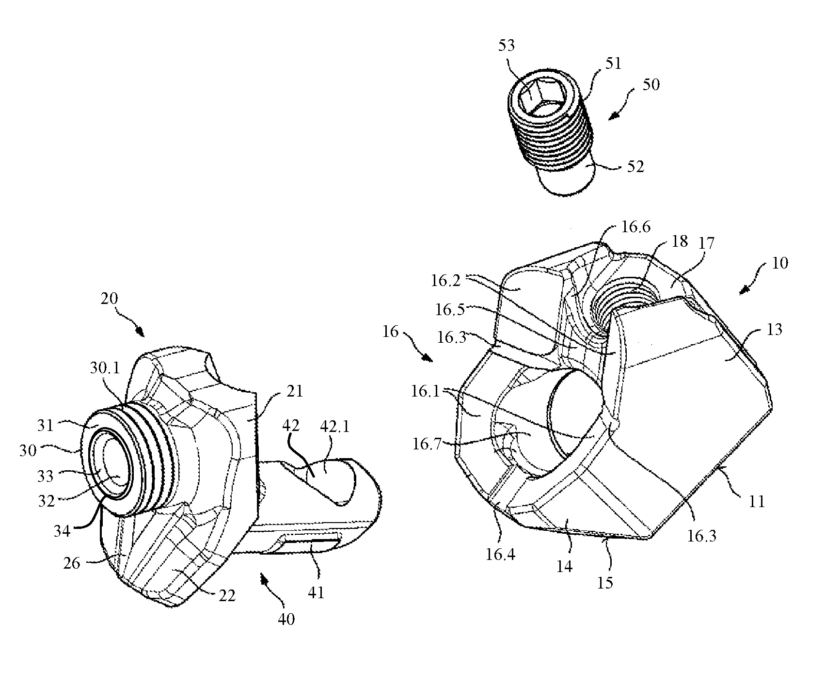
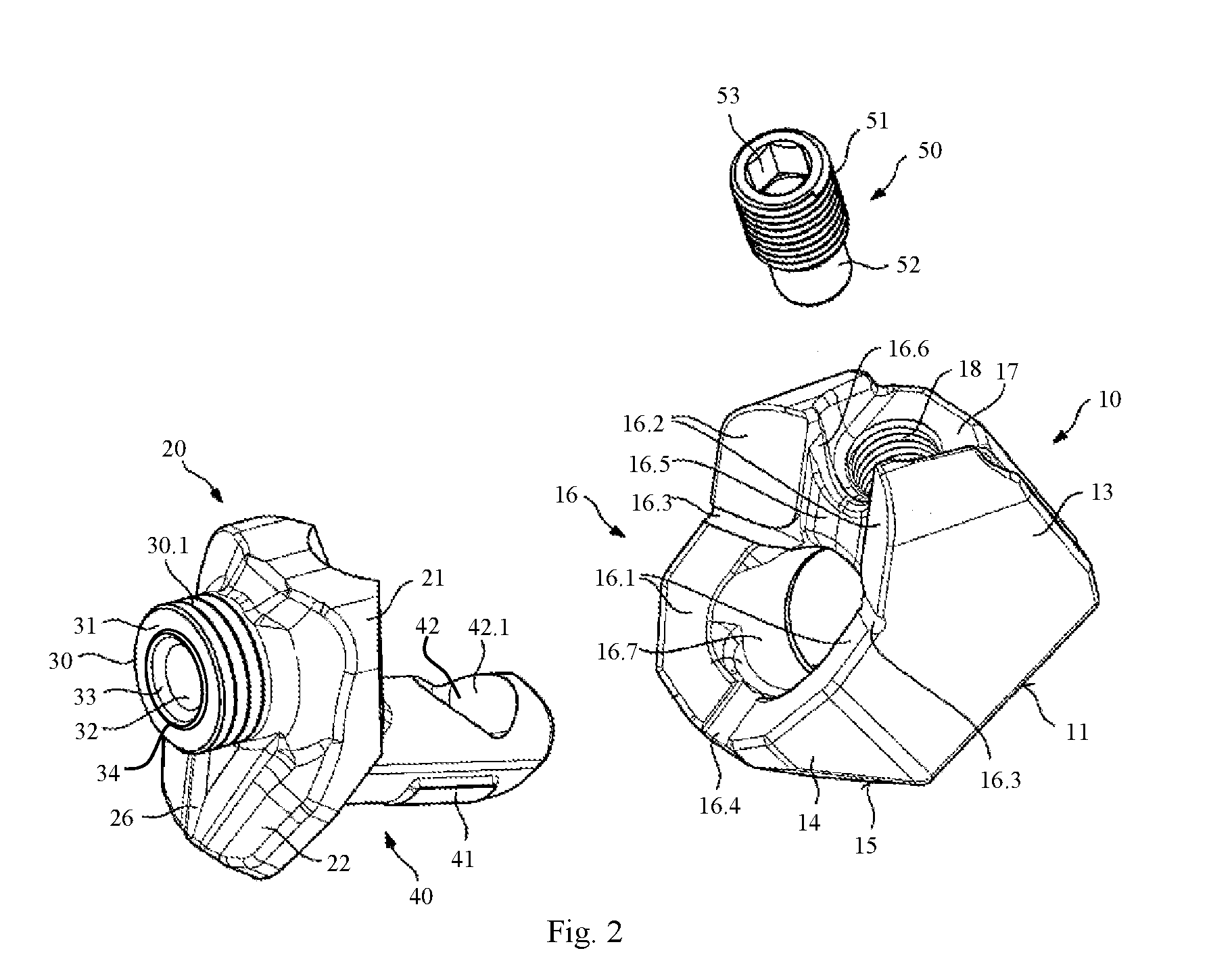
[0025] FIG. 2 is an exploded view of the base mount with bit holder shown in FIG. 1;
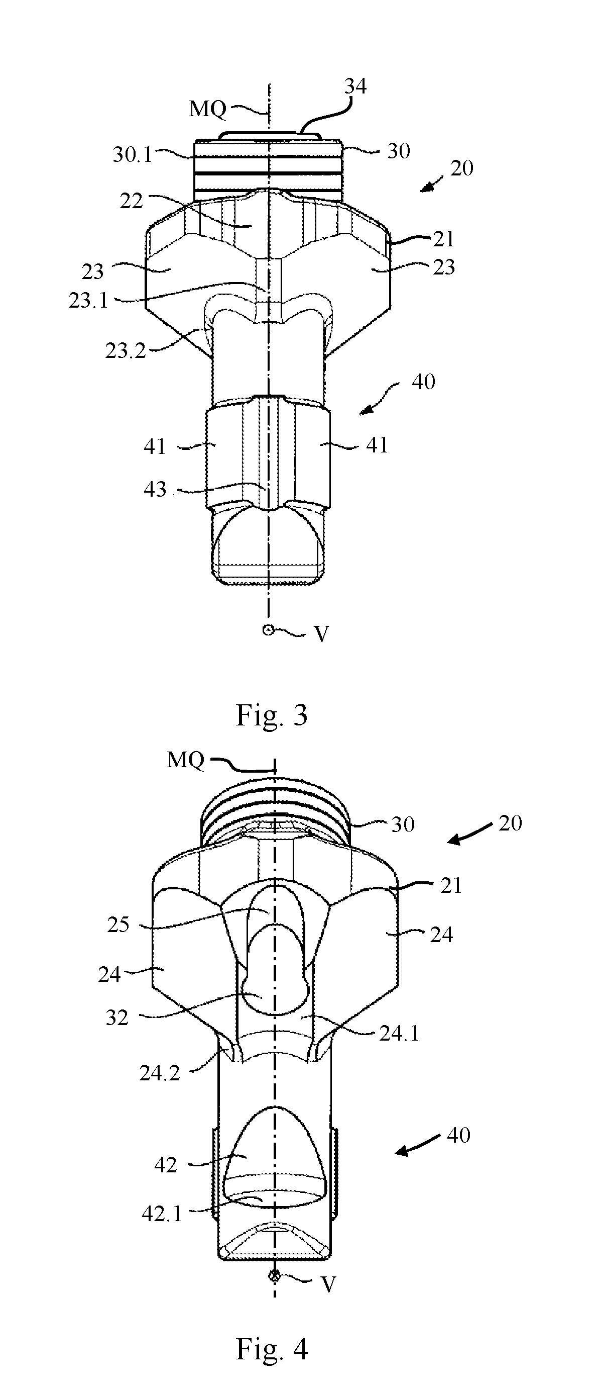
[0026] FIG. 3 is a front view of the bit holder shown in FIGS. 1 and 2;
[0027] FIG. 4 is a rear view of the bit holder shown in FIGS. 1, 2, and 3;
[0028] FIG. 5 is a detail of a tool system with a respective detail of a holding portion of the bit holder, a support element, and a round-shank bit held in the bit holder;
[0029] FIG. 6 schematically depicts the wear on a wear surface of a known bit holder; and
[0030] FIGS. 7 to 15 are respective schematic lateral section views of a detail of a holding portion in the region of a centering receptacle.
DETAILED DESCRIPTION
[0031] FIG. 1 is a perspective side view of a bit holder 20 detachably connected to a base mount 10. Oppositely from bit holder 20, base mount 10 is terminated by a concavely shaped lower terminating side 11. With this terminating side 11, base mount 10 can be fastened onto a milling drum tube (not shown) of an earth working machine, in the present case a road milling machine. Base mount 10 is preferably welded onto the milling drum tube so that large forces can be transferred. A base body 13 of base mount 10 has, at the front in a working direction, two inclined surfaces 15 arranged at an angle to one another and symmetrically with respect to one another in terms of a longitudinal center plane of base mount 10. Adjoining these at an angle are two oblique surfaces 14 arranged in mirror-image fashion with respect to the longitudinal center plane of base mount 10, only one of which is evident from the present perspective. Oblique surfaces 14 transition angularly into lateral surfaces of base body 13. The lateral surfaces are preferably oriented parallel to the working direction of base mount 10 during operation on a milling drum. The arrangement of inclined surfaces 15, oblique surfaces 14, and the adjoining lateral surfaces causes removed material to slide laterally past base mount 10.
[0032] Bit holder 20 comprises a support body 21 that is terminated at the front by a skirt 22. A holding portion 30 is shaped onto support body 21, facing away from base mount 10. Holding portion 30 is cylindrical in shape. Oppositely from support body 21, holding portion 30 is terminated by a wear surface 31. Wear surface 31 is arranged surroundingly with respect to a bit receptacle 32 of bit holder. Bit receptacle 32 is constituted by a cylindrical orifice; it is oriented along a longitudinal center axis M shown in FIGS. 6 to 15. Bit receptacle 32 widens in a beveled shape at its end facing toward wear surface 31, in the region of a centering receptacle 33. A projection 34, embodied in the present case in a ridge shape, is shaped on wear surface 31 surroundingly with respect to centering receptacle 33, and projects beyond the latter parallel to longitudinal center axis M. Wear markings 30.1 are provided on the outer surface of holding portion 30. Wear markings 30.1 are embodied in the present case as circumferential grooves. They are arranged at different distances from wear surface 31. Longitudinal wear on holding portion 30 can be recognized and evaluated on the basis of wear markings 30.1. Bit holder 20 is embodied symmetrically with respect to a transverse center plane MQ shown in FIGS. 3 and 4. That transverse center plane MQ receives longitudinal center axis M of bit receptacle 32 and extends in advance direction V, as is evident from FIGS. 3 and 4. Those surfaces of support body 21 and of skirt 22 which face away from base mount 10 constitute deflection surfaces for the removed material. They are oriented obliquely to transverse center plane MQ so that a land 26 oriented in the direction of transverse center plane MQ is formed in front of holding portion 30 in a working direction.
[0033] FIG. 2 is an exploded view of base mount 10, with bit holder 20, shown in FIG. 1. An insertion projection 40 is shaped onto support body 21 on that side of support body 21 which is located oppositely from holding portion 30 of bit holder 20. Insertion projection 40 is connected to support body 21 with an offset, in working direction V of bit holder 20, from holding portion 30. Said projection is oriented in its longitudinal extent toward base mount 10. Two abutment surfaces 41, only one of which is evident in the selected perspective, preferably project beyond the surface of insertion projection 40 in the working direction. In the context of the invention, a compression bolt receptacle 42 in the form of a recess is shaped into the insertion projection oppositely from the working direction. Compression bolt receptacle 42 is preferably terminated in a direction toward base mount 10 by a compression surface 42.1 proceeding obliquely to the longitudinal dimension of insertion projection 40.
[0034] Base mount 10 is penetrated by an insertion receptacle 16.7. Insertion receptacle 16.7 is oriented toward insertion projection 40 of bit holder 20. It serves to receive insertion projection 40. A threaded receptacle 18 is shaped into base mount 10, proceeding obliquely to insertion receptacle 16.7. It opens at the end into insertion receptacle 16.7. A compression bolt 50 is associated with threaded receptacle 18. Compression bolt 50 comprises a threaded portion 51, a tool receptacle 53, and a compression projection 52 located oppositely from tool receptacle 53. Said bolt can be screwed into threaded receptacle 18 of base mount 10 in such a way that compression projection 52 projects into insertion receptacle 16.7.
[0035] Laterally and frontwardly in the working direction, insertion receptacle 16.7 transitions into first support surfaces 16.1. The latter are oriented obliquely slopingly toward insertion receptacle 16.7, and symmetrically with respect to a center plane of base mount 10.
[0036] A surface 17 is embodied surroundingly with respect to threaded receptacle 18. Said surface is delimited laterally by protrusions projecting beyond surface 17. Toward insertion receptacle 16.7, the projections form two support surfaces 16.2. The latter are oriented at an angle to one another and obliquely slopingly with respect to insertion receptacle 16.7 and the center plane of base mount 10. They are furthermore arranged at an angle to first support surfaces 16.1. First and second support surfaces 16.1, 16.2 thus each constitute abutment surfaces, oriented in prism-shaped fashion toward one another, for support body 21 of bit holder 20. First and second support surfaces 16.1, 16.2 are oriented at an angle toward one another and are inclined slopingly toward insertion receptacle 16.2. Resetting spaces 16.3, 16.4, 16.5, in the form of depressions, are embodied along the angular transitions between support surfaces 16.1, 16.2. Resetting space 16.5 embodied between the two support surfaces 16.2 transitions via a cutout 16.6 into surface 17 that delimits threaded receptacle 18.
[0037] Insertion receptacle 16.7 and the delimiting support surfaces 16.1, 16.2 constitute a bit holder receptacle 16.
[0038] Bit holder 20 shown in FIGS. 1 and 2 is depicted in a front view in FIG. 3 and in a rear view in FIG. 4. Advance direction V, and thus the working direction of bit holder 20, are labeled in FIGS. 3 and 4 with the usual arrow depiction. Transverse center plane MQ proceeding in advance direction V forms a plane of symmetry of bit holder 20. As shown in FIG. 3, skirt 22 of support body 21, facing in advance direction V, forms on its side facing toward insertion projection 40 two first bearing surfaces 23 oriented at an angle to one another. First bearing surfaces 23 are preferably arranged mirror-symmetrically with respect to transverse center plane MQ. An asymmetrical arrangement is also conceivable. Bearing surfaces 23 are oriented to proceed obliquely to transverse center plane MQ. First bearing surfaces 23 form a first bearing-surface pair. A transition portion 23.1 can be provided between first bearing surfaces 23. First bearing surfaces 23 transition into insertion projection 40, preferably via a fillet transition 23.2. Insertion projection 40 comprises, in advance direction V, the two abutment surfaces 41 arranged mirror-symmetrically with respect to transverse center plane MQ. They can be separated from one another by a recess 43.
[0039] As depicted in FIG. 4, support body 21 forms second bearing surfaces 24 on its rear portion with respect to advance direction V, on its surface facing toward insertion projection 40. Second bearing surfaces 24 are oriented angularly and, with respect to transverse center plane MQ, preferably in mirror-image fashion with respect to one another. Second bearing surfaces 24 can of course also be located on both sides of transverse center plane MQ and do not need to be mirror images of one another. They can transition into insertion projection 40 via a fillet transition 24.2 or in sharp-edged fashion. An indirect transition is also conceivable. Second bearing surfaces 24 form a second bearing-surface pair. They can be separated from one another, for example, via a transition portion 24.1 embodied in throat-shaped fashion. Transition portion 24.1 can preferably proceed along transverse center plane MQ of bit holder 20. Bit receptacle 32, embodied as a passthrough orifice, opens into transition portion 24.1. A throat-shaped flushing channel 25 is guided to bit receptacle 32 oppositely to advance direction V. Flushing channel 25 forms a radially oriented opening in bit receptacle 32. Through it, removed material introduced into bit receptacle 32 during a milling process can be discharged outward.
[0040] For purposes of the present invention, for example, first bearing surfaces 23 can be interpreted as bearing surfaces of the bearing-surface pair, and one or both of second bearing surfaces 24 as (a) further bearing surface(s). Conversely, the two second bearing surfaces 24 can also form the bearing surfaces of the bearing-surface pair, and one or both first bearing surfaces 23 then form the further bearing surface(s). The "first/second bearing surfaces 23/24" terminology will continue to be used hereinafter.
[0041] For installation of bit holder 20 on base mount 10 shown in FIG. 2, insertion projection 40 is inserted into insertion receptacle 16.7 until support body 21 abuts with its first bearing surfaces 23 against first support surfaces 16.1, and with its second bearing surfaces 24 against second support surfaces 16.2, of base mount 10. Bearing surfaces 23, 24 and the associated support surfaces 16.1, 16.2 are each correspondingly oriented identically for that purpose. When bit holder 20 is completely inserted, compression bolt 50 is screwed into threaded receptacle 18 on base mount 10, in which context compression projection 52 engages into compression bolt receptacle 42 of insertion projection 40 and abuts at the end against compression surface 42.1. Bit holder 20 is thereby axially immobilized by compression bolt 50. Because of its orientation proceeding obliquely to the longitudinal dimension of insertion projection 40, compression bolt 50 presses the latter with its abutment surfaces 41 against the wall of insertion receptacle 16.7. At the same time, compression bolt 50 secures first and second bearing surfaces 23, 24 with respect to the associated first and second support surfaces 16.1, 16.2.
[0042] Bearing surfaces 23, 24 that proceed inclinedly with respect to insertion projection 40 make possible an optimized transfer of force to base mount 10 in a context of transverse forces acting from different directions on bit holder 20 and varying forces acting oppositely to advance direction V, since at least one of bearing surfaces 23, 24 is oriented with its surface normal line approximately in the direction of the resulting applied force. Force transfer from bit holder 20 to base mount 10 is thus accomplished in large part from bearing surfaces 23, 24 onto the corresponding support surfaces 16.1, 16.2. Loads on insertion projection 40 are thereby relieved, in particular in its transition region to support body 21. Premature fatigue breakage of insertion projection 40 can thus be avoided.
[0043] FIG. 5 shows a detail of a tool system with a respective detail of holding portion 30 of bit holder 20, a support element 70, and a round-shank bit 60 held in bit holder 20.
[0044] A bit head 61 of round-shank bit 60 is terminated, toward holding portion 30 of bit holder 20, by a collar 62. Collar 62 constitutes a resting surface 62.1 in a direction toward holding portion 30. That surface rests on a support surface 72 of support element 70. Support surface 72 is constituted inside a receptacle 71 on the upper side of support element 70, and is correspondingly delimited externally by a rim 71.1. On the sides located opposite support surface 72, support element 70 comprises a seating surface 73 with which it rests on wear surface 31 of holding portion 30 of bit holder 20. Support element 70 is constructed substantially rotationally symmetrically with respect to a longitudinal center axis of round-shank bit 60. Seating surface 73 transitions via a surrounding recess 75 into a counterpart centering surface 74.1, proceeding inclinedly with respect to the longitudinal center axis of support element 70, of a centering projection 74. As is clearly illustrated by FIG. 5, centering projection 74 of support element 70 is inserted into the correspondingly shaped centering receptacle 33 of bit holder 20. Counterpart centering surface 74.1 thus abuts against a corresponding centering surface 33.1 of centering receptacle 33. Projection 34 of holding portion 30 engages into recess 75.
[0045] Support element 70 has, along the longitudinal center axis, a receiving orifice 77 by which a guidance region 76 is constituted for guidance of round-shank bit 60. In the installed position shown, a centering portion 63 of a bit shank of round-shank bit 60 is associated with guidance region 76. A pivot bearing mount is thereby produced between guidance region 76 and centering portion 63. Care should be taken here that the outside diameter of the cylindrical centering portion 63 is coordinated with the inside diameter of receiving orifice 77 in guidance region 76 in such a way that free rotatability between support element 70 and centering portion 63 is maintained. The play between those two components should be selected so that the least possible lateral offset (transversely to the longitudinal center axis of round-shank bit 60) occurs. Centering portion 63 transitions, after a taper region 63.1, into the cylindrical bit shank that is concealed in the present case by a fastening sleeve 64.
[0046] The bit shank is retained axially by means of fastening sleeve 64 in bit receptacle 32 on holding portion 30 of bit holder 20. The retention permits an axial play 80. Fastening sleeve 64 comprises a bevel at its upper end.
[0047] During operation, round-shank bit 60 can rotate around its longitudinal center axis. The free rotatability ensures that round-shank bit 60 wears evenly over its entire circumference. Support element 70, which is loosely placed on and held by centering portion 63 of the bit shank, also rotates in this context, with the result that the overall rotatability of round-shank bit 60 is further improved. The rotation and the high mechanical loading of round-shank bit 60 cause wear to occur on bit holder 20, principally in the upper portion of holding portion 30. The load causes wear surface 31 to be worn away. The wear existing on holding portion 30 can be evaluated by way of wear markings 30.1.
[0048] The engagement of centering projection 74 into centering receptacle 33, and of projection 34 into recess 75, results in lateral guidance of support element 70, which has a positive effect on the rotatability of support element 70 and thus of round-shank bit 60. Centering surface 33.1 transitions tangentially into the surface of projection 34. Farther on, the surface of projection 34 is transitioned in rounded fashion into wear surface 31. Correspondingly, counterpart centering surface 74.1 of centering projection 74 of support element 70 transitions tangentially into recess 75, and the surface of recess 75 transitions in rounded fashion into seating surface 73 of support element 70. Edges that impede the rotatability of support element 70 and thus of round-shank bit 60 are thereby avoided. With its radial outer surface portion, projection 34 counteracts forces that act radially inward on support element 70. Forces directed radially outward are counteracted by the radially inner surface portion of projection 34. The force that must be absorbed by centering surface 33.1 of holding portion 30 is thereby reduced, resulting in decreased surface pressure, and correspondingly decreased wear, in this region. Guidance by projection 34 furthermore counteracts a tumbling motion in the disk plane of support element 70, producing a further reduction in wear at bit holder 20.
[0049] FIG. 6 schematically depicts the wear on wear surface 31 of a known bit holder 30 in the context of an asymmetrical load on support element 70 that is shaped complementarily to wear surface 31 and to centering receptacle 33. In the embodiment shown, the disk-shaped support element 70 is delimited by a flat support surface 72 and by an oppositely located, likewise flat, seating surface 73. Centering projection 74 is shaped on seating surface 73 with its counterpart centering surface 74.1 surrounding the central receiving orifice 77. Receiving orifice 77 has, on the side of support surface 72, an introduction chamfer 76.1 that facilitates insertion of the bit shank.
[0050] The asymmetrical load is depicted by way of two arrows of different lengths which symbolize a first force 83.1 and a second force 83.2 greater compared thereto. The asymmetrical force introduction can be brought about, for example, by the position of bit holder 20 with respect to the rotation direction of the milling drum. An uneven axial load of this kind results, in the context of a larger lateral motion (radial motion 82) of support element 70, in asymmetrical wear on wear surface 31 of bit holder 20. This is indicated by an orientation of wear surface 31 which is inclined at a wear angle 84 with respect to a plane proceeding perpendicularly to longitudinal center axis M. Radial motion 82 is made possible in a context of insufficient lateral guidance of support element 70. As a result of this kind of asymmetrical erosion of wear surface 31, support element 70 that guides round-shank bit 60 rests on wear surface 31 obliquely to longitudinal center axis M. Receiving orifice 77 is thus not aligned exactly with longitudinal center axis M of bit receptacle 32. Smooth rotatability of round-shank bit 60 can be impeded or suppressed by this misalignment. Uneven erosion of wear surface 31 also results in severe longitudinal wear on holding portion 30.
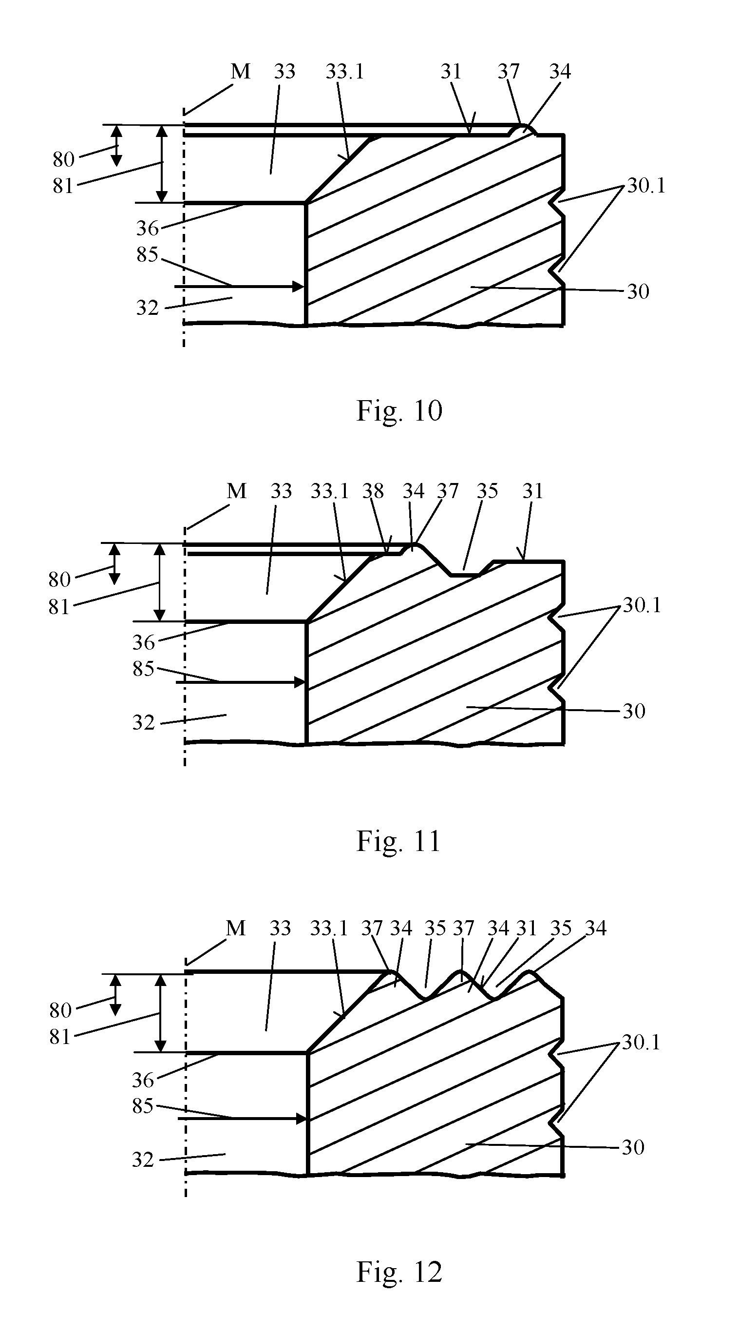
[0051] FIGS. 7 to 15 are schematic lateral section views each depicting a detail of a holding portion 30 of bit holder 20 in the region of centering receptacle 33. Only half of the rotationally symmetrically embodied holding portions 30, up to longitudinal center axis M of holding portion 30, is depicted in each case. The schematic depictions are not accurately to scale.
[0052] In the embodiment shown in FIG. 7, centering surface 33.1 of centering receptacle 33, oriented obliquely to longitudinal center axis M, transitions tangentially into the surface of projection 34. Projection 34 is transitioned at its outer termination in rounded fashion into wear surface 31 of holding portion 30. Projection 34 is embodied in the form of a ridge. It is arranged surroundingly with respect to centering receptacle 33. Projection 34 protrudes beyond wear surface 31. Projection 34 constitutes, at its highest point with respect to wear surface 31, a maximum point 37. The transition from centering surface 33.1 into the cylindrical enveloping surface of bit receptacle 32 forms one end 36 of centering receptacle 33. A centering height 81 labeled with a double arrow indicates in the present case the distance, measured in the direction of longitudinal center axis M, between end 36 of centering receptacle 33 and maximum point 37 of projection 34.
[0053] Projection 34 has a first radius 86 in a range between 0.5 mm and 6 mm, in the present case of 1.5 mm. The height of projection 34 with respect to wear surface 31 is preferably in a range between 0.3 mm and 2 mm, preferably between 0.5 mm and 1.5 mm, in the present case is 1.0 mm. Projection 34 transitions into wear surface 31 via the rounded region having a second radius 87. The transition from projection 34 to centering surface 33.1 of centering receptacle 33 proceeds continuously. Edges between centering surface 33.1, projection 34, and wear surface 31 are thus avoided. thereby improving free rotatability of an installed support element 70 around longitudinal center axis M.
[0054] Projection 34 is shaped onto holding portion 30 in the context of the manufacture of bit holder 20. When the tool system is installed, said projection engages into receptacle 75 of support element 70 as shown in FIG. 5. Inside diameter D.sub.i 85 of bit receptacle 32 is marked with an arrow.
[0055] According to the present invention, centering height 81 is designed in such a way that the ratio between inside diameter D.sub.i 85 of bit receptacle 32 and centering height 81 assumes a value of less than 8. Centering height 81 is defined by the axial dimensioning of centering receptacle 33 and of projection 34.
[0056] A ratio of less than 8 between inside diameter D.sub.i 85 of bit receptacle 32 of bit holder 20 and centering height 81 ensures good lateral guidance of support element 70 and thus of round-shank bit 60. In particular, centering height 81 is designed in such a way that it is greater than axial play 80 of round-shank bit 60 and thus of support element 70. The dimensioning of centering height 81 as a function of inside diameter D.sub.i 85 of bit receptacle 32 takes into account the greater permissible axial play 80 for larger tool systems. Sufficient lateral guidance of support element 70, and thus of round-shank bit 60, is thus ensured regardless of tool size.
[0057] Good radial guidance of support element 70 is also achieved, even with a maximum deflection of round-shank bit 60 out of bit receptacle 32 within the permissible axial play 80, by counterpart centering surface 74.1, abutting against centering surface 33.1 of centering receptacle 33, of centering projection 74 of support element 70. Further lateral guidance of support element 70 is achieved by way of recess 75 shown in FIG. 5 and projection 34, engaging thereinto, of bit holder 20. Lateral motions or tumbling motions of support element 70 can thereby reliably be avoided. Longitudinal wear on holding portion 30 of bit holder 20 can thus be considerably reduced. Asymmetrical wear on wear surface 31 in a context of uneven loading of support element 70, as described with reference to FIG. 6, can be avoided or at least considerably minimized. Consistently good rotation of round-shank bit 60 and of support element 70 is achieved by the absence of an angular offset, with reference to longitudinal center axis M, of wear surface 31 constituting an abutment surface for support element 70 and thus for round-shank bit 60.
[0058] Easy rotatability of support element 70 and of round-shank bit 60 is furthermore obtained by way of the rounded or continuous, and thus edge-free, transitions between centering surface 33.1, projection 34, and wear surface 31. Sharp transitions can easily cause support element 70 to tilt with respect to bit holder 20, and thereby prevent rotation. This can be avoided by the rounded or continuous transitions.
[0059] In the exemplifying embodiment of a holding portion 30 shown in FIG. 8, a guidance groove 35 is shaped into wear surface 31. Guidance groove 35 surrounds centering receptacle 33 at a distance. It has a trapezoidal contour having lateral surfaces proceeding inclinedly with respect to wear surface 31. Projection 34 is embodied between centering receptacle 33 and guidance groove 35. It too has a trapezoidal contour. In the exemplifying embodiment shown, projection 34 terminates in the same plane as wear surface 31 alongside guidance groove 35. Toward longitudinal center axis M, projection 34 transitions directly into the inclinedly proceeding centering surface 33.1 of centering receptacle 33. Here and in all the further embodiments described below, centering receptacle 33 is terminated by end 36 formed in the transition from centering surface 33.1 to the enveloping surface of bit receptacle 32.
[0060] A guidance land is shaped onto seating surface 73, surroundingly with respect to centering projection 74, onto seating surface 73 of a support element 70 that is not shown in FIG. 8 and is adapted to the end-face contour of holding portion 30. The guidance land has a contour complementary to guidance groove 35. The guidance land therefore engages into the corresponding guidance groove when the tool system is installed. Further lateral guidance of support element 70 is thereby achieved. Tumbling motions of support element 70 can thereby be very largely avoided. Longitudinal wear on holding portion 30 can be further reduced by way of guidance groove 35 and a guidance land engaging thereinto.
[0061] Centering height 81 is measured in the direction of longitudinal center axis M between end 36 of centering receptacle 33 and the upper surface of projection 34, as depicted by a double arrow. The ratio between inside diameter D.sub.i 85 of bit receptacle 32 and centering height 81 is selected to be less than 8, in the present case less than 6.5. Good lateral guidance of the support element is thereby achieved. With a ratio of less than 6.5, sufficient lateral guidance is achieved even toward the end of the service life of support element 70 and of round-shank bit 60, when axial play 80 of round-shank bit 60 may have become greater as a result of wear that has already occurred.
[0062] In a departure from the embodiment depicted, the transition from centering surface 33.1 to projection 34, and/or the transition from projection 34 to the adjoining lateral surface of guidance groove 35, and/or the transition from the oppositely located lateral surface of guidance groove 35 to the adjacent wear surface 31, can be rounded. The transitions from the lateral surfaces to the groove bottom can also be embodied in rounded fashion. Sharp edges can thereby be avoided, resulting in improved rotatability of support element 70.
[0063] With bit holder 20 shown in FIG. 9, a trapezoidal guidance groove 35 is once again shaped into wear surface 31. A projection 34 shaped on between guidance groove 35 and centering receptacle 33 has a ridge-shaped contour. The radius of projection 34 is selected so that its surface transitions tangentially into centering surface 33.1 of centering receptacle 33, and oppositely into the adjoining lateral surface of guidance groove 35. Centering height 81 corresponds to the distance, measured in the direction of longitudinal center axis M, between end 36 of centering receptacle 33 and maximum point 37 of projection 34. Good lateral guidance of support element 70 is achieved thanks to the immediately successive combination of centering recess 33, projection 34, and guidance groove 35 in conjunction with a seating surface 73, shaped correspondingly thereto, of a support element 70.
[0064] Wear surface 31 of holding portion 30 shown in FIG. 10 transitions directly into centering surface 33.1 of centering receptacle 33. In the outer region of wear surface 31, a ridge-shaped projection 34 is shaped thereonto. Centering height 81 is measured along longitudinal center axis M between end 36 of centering receptacle 33 and maximum point 37 of projection 34. The arrangement of projection 34 comparatively far outward on holding portion 30 results in particularly good stabilization of the rotational motion of an abutting support element 70 embodied correspondingly thereto.
[0065] FIG. 11 shows a holding projection 30 having a surface that faces toward a support element 70 (not shown) and is embodied in multiple steps. Centering surface 33.1 transitions into an abutment surface 38 arranged transversely to longitudinal center axis M, in particular perpendicularly to longitudinal center axis M. Adjoining abutment surface 38 is a projection 34 that protrudes beyond abutment surface 38. The surface of the ridge-shaped projection 34 transitions tangentially into the adjoining lateral surface of a trapezoidally embodied guidance groove 35. Wear surface 31 is arranged surroundingly with respect to the guidance groove. Abutment surface 38, maximum point 37 of projection 34, the groove bottom of guidance groove 35, and wear surface 31 are arranged on different planes along longitudinal center axis M. Measured parallel to longitudinal center axis M, maximum point 37 is spaced the farthest from end 36 of centering receptacle 33, followed by abutment surface 38, wear surface 31, and the groove bottom of guidance groove 35. Thanks to this profile, implemented over different planes, of the end surface of holding portion 30, very good lateral guidance of a support element 70 embodied correspondingly thereto is achieved. Both result in decreased wear on holding portion 30 and thus on bit holder 20.
[0066] In the exemplifying embodiment of bit holder 20 shown in FIG. 12, projections 34 arranged concentrically with one another are shaped onto holding portion 30 around centering receptacle 33. A wave-shaped contour, whose surface represents wear surface 31, is thereby formed. Centering height 81 is measured between end 36 of centering receptacle 33 and maximum point 37 of the innermost projection 34. When neighboring projections 34 have different heights, centering height 81 is preferably determined at maximum point 37 of the highest projection 34. Good rotatability of a corresponding support element 70 is ensured by projections 34 arranged surroundingly with respect to centering receptacle 33. As a result of the wave-shaped contour, the surface of holding portion 30 projected in an axial direction remains equivalent to a flat plane, so that the axial supporting effect is maintained. The radially effective area is considerably enlarged by the lateral flanks of projections 34. Transverse forces can thereby be better absorbed. The contact area between a support element 70 and holding portion 30 of bit holder 20 is enlarged by the wave shape. This leads to reduced wear on bit holder 20 and improved rotatability of support element 70 and thus of round-shank bit 60.
[0067] FIG. 13 shows a detail of a bit holder 20 having a flat wear surface 31 onto which two ridge-shaped projections 34, proceeding concentrically with one another, are shaped. Good rotatability and good lateral stabilization are achieved with this arrangement as well.
[0068] Bit holder 20 depicted in FIG. 14 has a wear surface 31 that proceeds linearly but is oriented obliquely to longitudinal center axis M. Maximum point 37 is embodied in the rounded transition region from centering surface 33.1 into wear surface 31. Because of their orientation obliquely to longitudinal center axis M, both centering surface 33.1 and wear surface 31 have a radially stabilizing effect on the position of a support element 70 that is adapted to wear surface 31 in terms of the contour of its seating surface 73. Centering height 81 is measured, in the direction of longitudinal center axis M, from end 36 of centering receptacle 33 to maximum point 37 at the transition from centering surface 33.1 to wear surface 31.
[0069] With bit holder 20 shown in FIG. 15, wear surface 31 proceeds obliquely to longitudinal center axis M of holding portion 30. The greatest distance, measured in the direction of longitudinal center axis M, between end 36 of centering receptacle 33 and wear surface 31 is obtained at the outer rim of holding portion 30, so that that distance constitutes centering height 81. In this exemplifying embodiment as well, both centering surface 33.1 and wear surface 31 oriented obliquely to longitudinal center axis M have a radially stabilizing effect on a correspondingly shaped abutting support element 70.
[0070] In summary, it can be stated that thanks to the embodiment according to the present invention of holding portion 30 of bit holder 20, in which the ratio between inside diameter D.sub.i 85 of bit receptacle 32 and centering height 81 is less than 8, and/or in which centering height 81 is greater than an axial play 80 of a round-shank bit 60 installed in bit holder 20, longitudinal wear on holding portion 30 in relation to the operating time of the tool system can be considerably reduced. Tilting of round-shank bit 60 upon initial operation can be almost avoided thanks to the improved and more-stable engagement of projection(s) 34 into recesses 75 of a support element 70 which correspond thereto. Longitudinal wear on holding portion 30 is thereby evened out. The bit shank, and bit receptacle 32, are better protected from contaminants by the enhanced sealing effect of the resting surface between support element 70 and holding portion 30. This too results in considerably reduced wear on bit holder 20 in the region of its holding portion 30. Premature wear on or fatigue breakage of insertion projection 40 of bit holder 20 can be avoided by embodying bearing surfaces 23, 24 to abut against correspondingly embodied support surfaces 16.1, 16.2 of base mount 10. The life expectancy of bit holder 20 as an assembly can thus be considerably extended by the features. This results in reduced costs for maintenance and replacement parts.
* * * * *
D00000
D00001
D00002
D00003
D00004
D00005
D00006
D00007
XML
uspto.report is an independent third-party trademark research tool that is not affiliated, endorsed, or sponsored by the United States Patent and Trademark Office (USPTO) or any other governmental organization. The information provided by uspto.report is based on publicly available data at the time of writing and is intended for informational purposes only.
While we strive to provide accurate and up-to-date information, we do not guarantee the accuracy, completeness, reliability, or suitability of the information displayed on this site. The use of this site is at your own risk. Any reliance you place on such information is therefore strictly at your own risk.
All official trademark data, including owner information, should be verified by visiting the official USPTO website at www.uspto.gov. This site is not intended to replace professional legal advice and should not be used as a substitute for consulting with a legal professional who is knowledgeable about trademark law.