Splash-proof Covers For Drains And Methods Of Use
Radl; Christopher L. ; et al.
U.S. patent application number 16/136640 was filed with the patent office on 2019-04-11 for splash-proof covers for drains and methods of use. The applicant listed for this patent is Boehringer Technologies, LP. Invention is credited to Bradley Boehringer, William C. Dackis, Kevin Klocek, Helmut Laenger, Barbara McConnell, Nora Powell, Christopher L. Radl, Trevor Smith.
| Application Number | 20190106869 16/136640 |
| Document ID | / |
| Family ID | 65993871 |
| Filed Date | 2019-04-11 |


| United States Patent Application | 20190106869 |
| Kind Code | A1 |
| Radl; Christopher L. ; et al. | April 11, 2019 |
SPLASH-PROOF COVERS FOR DRAINS AND METHODS OF USE
Abstract
Disclosed are splash-proof covers and methods of use to prevent liquid within a pipe under the drain of a sink having a basin from splashing out of the sink. The covers include a central body portion having an undersurface from which plural spaced apart, suction cups project downward. The covers may include an anti-microbial and/or anti-fungal agent and are configured to be disposed in the sink with each of the suction cups releasably engaging respective portions of the basin surrounding the drain and with the central body portion being located directly over the drain and spaced slightly thereabove. The central body portion enables water from a faucet to flow under it into the drain while providing a barrier to prevent any liquid within a pipe under the drain from splashing back into the sink.
| Inventors: | Radl; Christopher L.; (Malvern, PA) ; Boehringer; Bradley; (West Kingston, RI) ; McConnell; Barbara; (Malvern, PA) ; Klocek; Kevin; (Feasterville, PA) ; Laenger; Helmut; (Huntingdon Valley, PA) ; Powell; Nora; (West Chester, PA) ; Smith; Trevor; (West Chester, PA) ; Dackis; William C.; (Medford, NJ) | ||||||||||
| Applicant: |
|
||||||||||
|---|---|---|---|---|---|---|---|---|---|---|---|
| Family ID: | 65993871 | ||||||||||
| Appl. No.: | 16/136640 | ||||||||||
| Filed: | September 20, 2018 |
Related U.S. Patent Documents
| Application Number | Filing Date | Patent Number | ||
|---|---|---|---|---|
| 62570169 | Oct 10, 2017 | |||
| 62679126 | Jun 1, 2018 | |||
| Current U.S. Class: | 1/1 |
| Current CPC Class: | A47K 1/14 20130101; E03C 1/186 20130101; E03C 1/264 20130101; E03C 1/181 20130101 |
| International Class: | E03C 1/181 20060101 E03C001/181; E03C 1/186 20060101 E03C001/186 |
Claims
1. A splash-proof cover for a sink including drain and a basin surrounding the drain, said splash-proof cover comprising: a central body portion having an upper surface and an undersurface; and plural suction cups connected to said central body portion, each of said suction cups projecting downward from the undersurface of said central body portion, said suction cups being spaced from one another, said splash-proof cover being configured to be disposed in said sink with each of said suction cups releasably engaging by suction respective portions of the basin surrounding the drain and with said central body portion being located directly over the drain and spaced slightly thereabove, whereupon said central body portion shields the drain from above but enables water from a faucet to flow under said central body portion into the drain and with said central body portion providing a barrier to prevent any liquid within a pipe under the drain from splashing back into the sink.
2. The splash-proof cover of claim 1, wherein said upper surface is contoured to reduce splashing of water from the faucet which impacts said upper surface.
3. The splash-proof cover of claim 2, wherein said upper surface is convex and at least a portion of said undersurface is concave.
4. The splash-proof cover of claim 2, wherein said central body portion additionally comprises plural reinforcing ribs projecting downward from said undersurface.
5. The splash-proof cover of claim 1, wherein said splash-proof cover is formed of a flexible material.
6. The splash-proof cover of claim 5, wherein said flexible material comprises a plastic.
7. The splash-proof cover of claim 1, wherein said splash-proof cover additionally comprises three legs projecting outward from said central body portion, each of said legs including an undersurface from which a respective one of said suction cups projects downward.
8. The splash-proof cover of claim 2, wherein said contoured upper surface comprises a plurality of spikes.
9. The splash-proof cover of claim 1, additionally comprising at least one projection extending upward from said splash-proof cover to enable said splash proof cover to be grasped thereby to facilitate removal of said splash-proof cover from said sink.
10. The splash proof-cover of claim 9, wherein said at least one projection comprises a tab located adjacent one of said suction cups.
11. The splash-proof cover of claim 1, wherein said upper surface terminates in an annular rim in the form a return extending under a portion of said undersurface to increase the distance that any microbes on said undersurface have to traverse to reach said upper surface.
12. The splash-proof cover of claim 11, wherein said upper surface is convex.
13. The splash-proof cover of claim 1, additionally comprising an anti-microbial agent.
14. The splash-proof cover of claim 13, wherein said anti-microbial agent is an additive to a plastic resin which molded to form said splash-proof cover.
15. The splash-proof cover of claim 13, wherein said anti-microbial agent comprises a coating on said splash-proof cover.
16. The splash-proof cover of claim 13, wherein said anti-microbial agent comprises a flexible LED or OLED panel operative when activated to provide anti-microbial UV light from said upper surface.
17. The splash-proof cover of claim 16, wherein said LED or OLED panel is configured to be activated by water pressure.
18. The splash-proof cover of claim 1, additionally comprising a color change agent.
19. The splash-proof cover of claim 18, wherein said color change agent changes color upon exposure to gram negative bacteria.
20. The splash-proof cover of claim 18, wherein said color change agent changes color when the amount of gram negative bacteria reaches a predetermined threshold value.
21. The splash-proof cover of claim 18, wherein said color change agent provides a visible color that dissipates as water is run over said splash-proof cover.
22. The splash-proof cover of claim 18, wherein said color change agent changes color over time.
23. A method of preventing liquid within a pipe under a drain of a sink from splashing out of said sink, said sink including a drain and a basin surrounding said drain, said method comprising: providing a splash-proof cover comprising a central body portion having an undersurface, a plural suction cups projecting downward from said undersurface of said central body portion, wherein said splash-proof cover is configured to provide an anti-microbial and/or an anti-fungal effect; causing said suction cups to releasably engage respective portions of said basin surrounding said drain, whereupon said central body portion is located directly over said drain and spaced slightly thereabove to shield said drain from above but enabling water from a faucet to flow under said central body portion into said drain and with said central body portion providing a barrier to prevent any liquid within a piper under said drain from splashing back into said sink.
24. The method of claim 23, wherein said splash-proof cover is located in a room in a medical facility.
25. The method of claim 23, wherein said splash-proof cover is removed from said sink and disposed of upon cleaning of said room.
Description
FIELD OF THE INVENTION
[0001] This invention relates generally to infection control devices and methods and more particularly to devices and methods for preventing splashing of contaminated liquids from pipes under sink drains.
CROSS-REFERENCE TO RELATED APPLICATIONS
[0002] This utility application claims the benefit under 35 U.S.C. .sctn. 119(e) of Provisional Application Ser. No. 62/570,169 filed on Oct. 10, 2017, entitled Splash-Proof Sink Drain Cover and Method of Use, and Provisional Application Ser. No. 62/679,126, filed on Jun. 1, 2018, entitled Splash-Proof Covers for Drains and Methods of Use. The entire disclosures of these provisional applications are incorporated by reference herein.
SPECIFICATION
Background of the Invention
[0003] Infection control is an important issue in modern hospitals. With the increase in drug resistant bacteria, a greater emphasis is being placed on infection prevention than ever before. As new sources of contamination are identified, it has become apparent that sinks are a definitive culprit. Resting water in the pipe directly under the sink drain can become a breeding ground for bacteria, other microbes and viruses. In many sinks, the drains are positioned just under the faucet head so when water leaves the faucet it hits the standing water below the drain directly. This may create a spray of contaminated water that spreads the bacteria, fungi, etc., to neighboring surfaces.
[0004] Thus, a need exists for a device which will enable a sink drain to operate in a normal manner to enable water from a faucet to flow into the drain, while preventing any splashing of liquids from the drain pipe back into the sink, even if the faucet is located directly above the drain. The subject invention addresses that need.
BRIEF SUMMARY OF THE INVENTION
[0005] One aspect of this invention is a splash-proof cover for a sink including drain and a basin surrounding the drain. The splash-proof cover comprises a central body portion having an upper surface, an undersurface and plural suction cups connected to the central body portion. Each of the suction cups projects downward from the undersurface of the central body portion. The suction cups are spaced apart from one another. The splash-proof cover is configured to be disposed in the sink with each of the suction cups releasably engaging by suction respective portions of the basin surrounding the drain and with the central body portion being located directly over the drain and spaced slightly thereabove. As such, the central body portion shields the drain from above but enables water from a faucet to flow under the central body portion into the drain and with the central body portion providing a barrier to prevent any liquid within a pipe under the drain from splashing back into the sink.
[0006] In accordance with one preferred aspect of the splash-proof cover of this invention, the upper surface is contoured to reduce splashing of water from the faucet which impacts the upper surface.
[0007] In accordance with another preferred aspect of the splash-proof cover of this invention, the contoured upper surface comprises a plurality of spikes.
[0008] In accordance with another preferred aspect of the splash-proof cover of this invention, the splash-proof cover additionally comprises at least one projection extending upward from the splash-proof cover to enable the splash proof cover to be grasped thereby to facilitate removal of the splash-proof cover from the sink.
[0009] In accordance with another preferred aspect of the splash-proof cover of this invention, the at least one projection comprises a tab located adjacent one of the suction cups.
[0010] In accordance with another preferred aspect of the splash-proof cover of this invention, the upper surface terminates in an annular rim in the form a return extending under a portion of the undersurface to increase the distance that any microbes on the undersurface have to traverse to reach the upper surface.
[0011] In accordance with another preferred aspect of the splash-proof cover of this invention, the upper surface is convex.
[0012] In accordance with another preferred aspect of the splash-proof cover of this invention, the splash-proof cover additionally comprises an anti-microbial agent.
[0013] In accordance with another preferred aspect of the splash-proof cover of this invention, the anti-microbial agent is an additive to a plastic resin which molded to form the splash-proof cover.
[0014] In accordance with another preferred aspect of the splash-proof cover of this invention, the anti-microbial agent comprises a coating on the splash-proof cover.
[0015] In accordance with another preferred aspect of the splash-proof cover of this invention, the anti-microbial agent comprises a flexible light emitting diode ("LED") panel or organic light emitting diode ("OLED") panel that is operative when activated to provide anti-microbial UV light from its upper surface.
[0016] In accordance with another preferred aspect of the splash-proof cover of this invention, the LED panel or OLED panel is configured to be activated by water pressure.
[0017] In accordance with another preferred aspect of the splash-proof cover of this invention, the splash-proof cover additionally comprises a color change agent.
[0018] In accordance with another preferred aspect of the splash-proof cover of this invention, the color change agent changes color upon exposure to gram negative bacteria.
[0019] In accordance with another preferred aspect of the splash-proof cover of this invention, the color change agent changes color when the amount of gram negative bacteria reaches a predetermined threshold value.
[0020] In accordance with another preferred aspect of the splash-proof cover of this invention, the color change agent provides a visible color that dissipates as water is run over the splash-proof cover.
[0021] In accordance with another preferred aspect of the splash-proof cover of this invention, the color agent changes color over time.
[0022] Another aspect of this invention is a method of preventing liquid within a drain pipe under a drain of a sink from splashing out of the sink. The sink includes a drain and a basin surrounding the drain. The method comprises providing a splash-proof cover comprising a central body portion having an undersurface, and plural suction cups projecting downward from the undersurface of the central body portion. The splash-proof cover is configured to provide an anti-microbial and/or an anti-fungal effect and is located within the sink so that the suction cups releasably engage respective portions of the basin surrounding the drain, whereupon the central body portion is located directly over the drain and spaced slightly thereabove to shield the drain from above but enabling water from a faucet to flow under the central body portion into the drain. The central body portion provides a barrier to prevent any liquid within a pipe under the drain from splashing back into the sink.
[0023] In accordance with one preferred aspect of the method of this invention, the sink is located in a room in a medical facility.
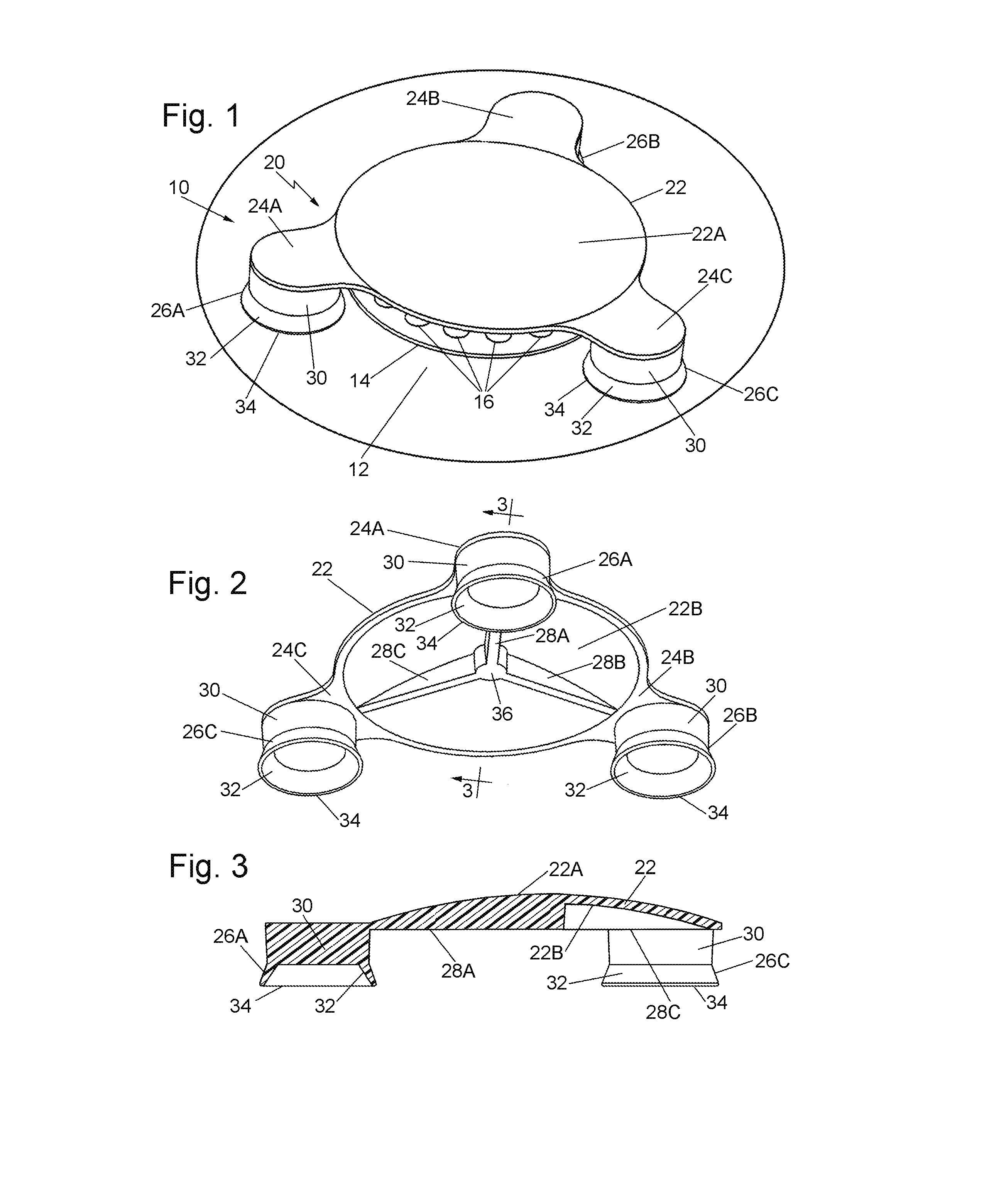
BRIEF DESCRIPTION OF SEVERAL VIEWS OF THE DRAWINGS
[0024] FIG. 1 is an isometric view of one exemplary embodiment of a splash-proof drain cover constructed in accordance with this invention and shown in place in an exemplary sink;
[0025] FIG. 2 is another enlarged isometric view of the splash-proof sink drain of FIG. 1, but showing the underside thereof;
[0026] FIG. 3 is sectional view taken along line 3-3 of FIG. 2;
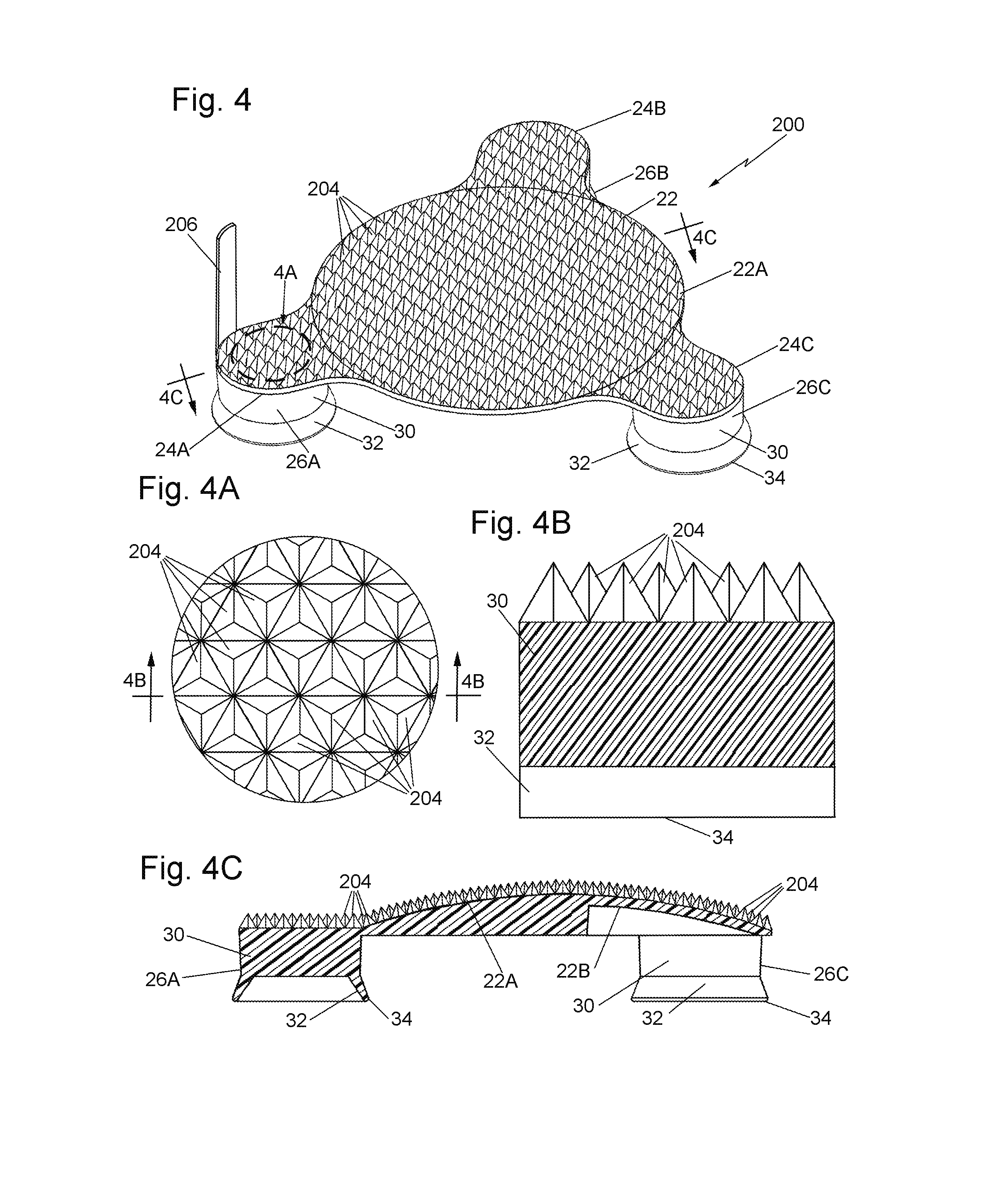
[0027] FIG. 4 is an isometric view similar to FIG. 1, but showing another exemplary embodiment of a splash-proof drain cover constructed in accordance with this invention, wherein the cover includes a contoured, e.g., spiked, upper surface to further reduce splashing;
[0028] FIG. 4A is an enlarged top plan view of the portion of the contoured upper surface of the splash-proof drain cover shown within the area designed by the reference number 4A in FIG. 4;
[0029] FIG. 4B is an enlarged sectional view taken along line 4B-4B of FIG. 4A;
[0030] FIG. 4C is a sectional view taken along line 4C-4C of FIG. 4;
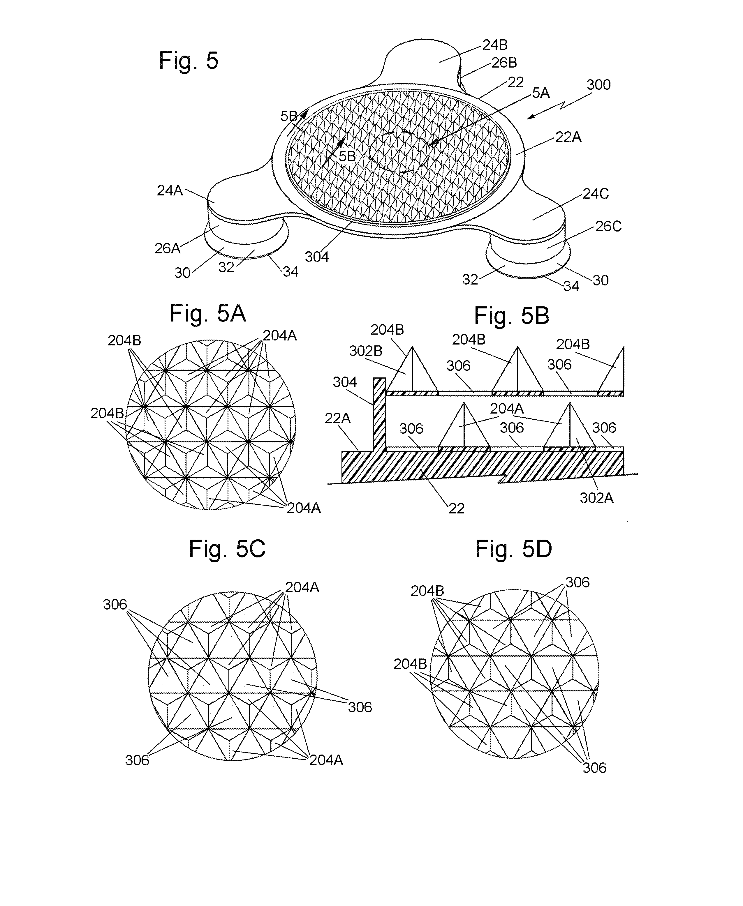
[0031] FIG. 5 is an isometric view similar to FIG. 4, but showing another exemplary embodiment of a splash-proof drain cover constructed in accordance with this invention and having a contoured, e.g., spiked, upper surface to further reduce splashing, wherein the spiked upper surface is formed by an uppermost spiked layer and a lowermost spiked layer which are interleaved;
[0032] FIG. 5A is an enlarged top plan view of the portion of the contoured upper surface of the splash-proof sink drain cover shown within the area designed by the reference number 5A in FIG. 5;
[0033] FIG. 5B is an enlarged sectional view taken along line 5B-5B of FIG. 5;
[0034] FIG. 5C is a top plan view of the lowermost of the two interleaved spiked layers shown within the same area as that of FIG. 5A;
[0035] FIG. 5D is a top plan view of the uppermost of the two interleaved spiked layers shown within the same area as that of FIG. 5A;
[0036] FIG. 6 is an isometric view similar to FIG. 1, but showing another exemplary embodiment of a splash-proof drain cover having constructed in accordance with this invention and having a peripheral underhanging annular rim to serve as a return;
[0037] FIG. 7 is an enlarged sectional view taken along line 7-7 of FIG. 6;
[0038] FIG. 8 is an isometric view similar to FIG. 6, but showing another exemplary embodiment of a splash-proof drain cover constructed in accordance with this invention, wherein the splash-proof cover includes an anti-microbial agent and/or a color indicating agent in the form of a coating or layer on the splash-proof cover;
[0039] FIG. 9 is an enlarged sectional view taken along line 9-9 of FIG. 8;
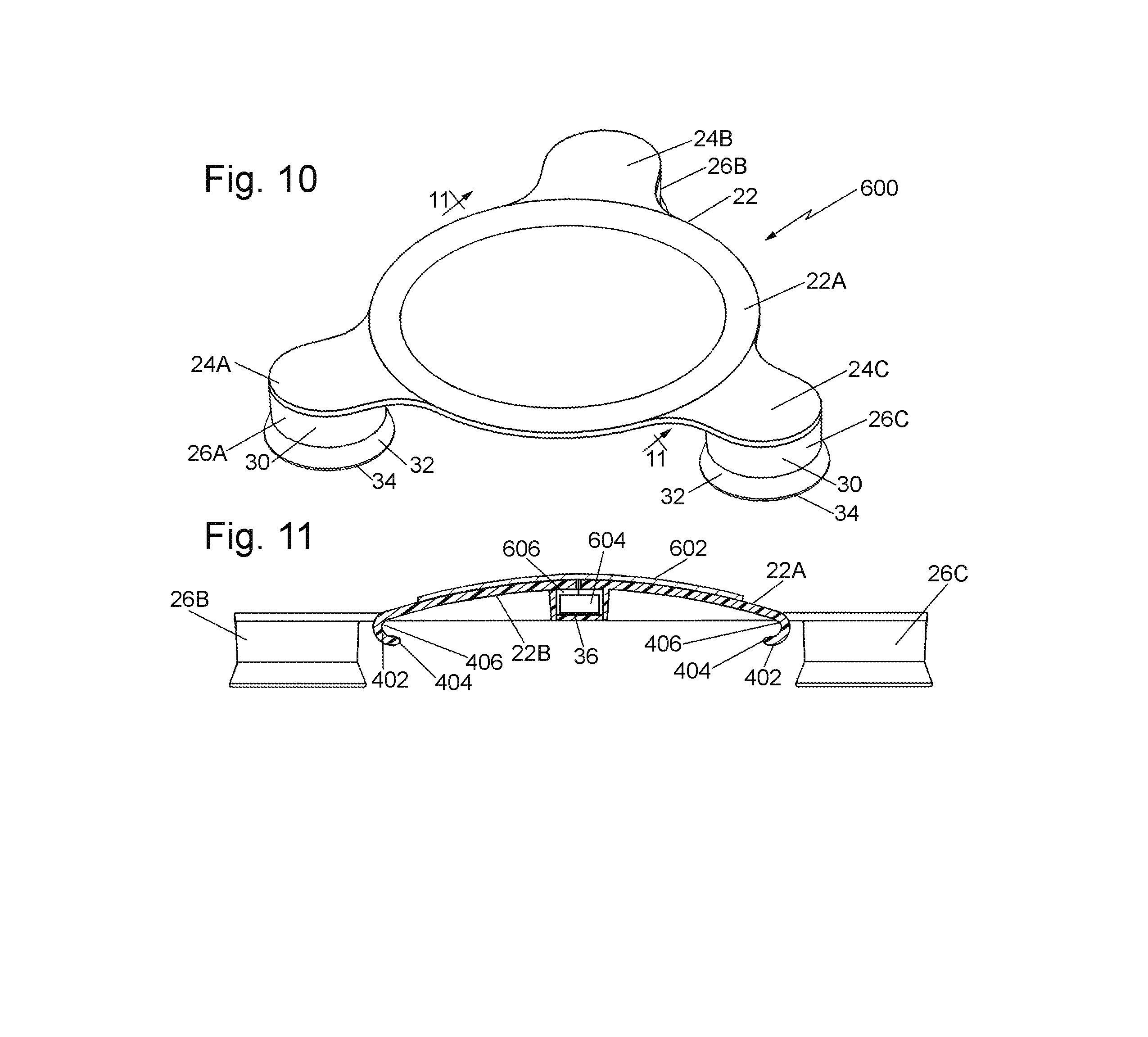
[0040] FIG. 10 is an isometric view, similar to FIGS. 6 and 8, but showing still another exemplary embodiment of a splash-proof sink drain cover constructed in accordance with this invention, wherein the splash-proof cover includes a flexible LED or OLED panel for producing anti-microbial UV light; and
[0041] FIG. 11 is an enlarged sectional view taken along line 11-11 of FIG. 10, and showing the components for activating and energizing the flexible LED or OLED panel.
DETAILED DESCRIPTION OF THE PREFERRED EMBODIMENTS OF THE INVENTION
[0042] Referring now to the various figures of the drawing wherein like reference characters refer to like parts, there is shown in FIG. 1 one exemplary splash-proof drain cover 20 constructed in accordance with this invention. The cover is shown in its operative position in a sink 10. The sink 10 is conventional and comprises a basin 12, a drain 14 at the bottom of the basin, a drain pipe (not shown) located under the drain, and a faucet (not shown) located over the basin. In the exemplary embodiment the drain includes plural holes or apertures 16 through which liquid in the basin can flow into the drain pipe. It should be pointed out at this juncture that the sink and drain are merely exemplary of a myriad of sinks and drains for which the subject splash-proof cover has utility.
[0043] The splash proof-cover 20 is constructed so that when in the operative position within the basin 12 and it creates a physical barrier between water leaving the faucet and contaminated standing water within the drain pipe under the drain. This prevents splash back and the spread of bacteria, etc., to surrounding surfaces.
[0044] The splash-proof cover 20 is preferably a one-piece unit comprising a central body portion 22 from which plural, e.g., three, legs 24A, 24B, and 24C project outward. The underside of each of the legs is in the form of a downwardly facing suction cup. Thus, there are three, flexible suction cups 26A, 26B, and 26C. Each suction cup includes a solid upper portion 30, from which a slightly outwardly flared flexible sidewall 32 extends downward. Each sidewall terminates in a circular free edge 34. The central body portion 22 is located above the sidewalls 32 of the suction cups and is of generally circular profile, although it could be of other shapes. In any case, the central body portion 22 includes an upper convex surface 22A (FIG. 3) and a lower concave surface 22B (FIG. 3). Three reinforcing ribs 28A, 28B, and 28C project downward from the concave surface 22B. Each of the ribs extends from a central hub 36 outward toward a respective suction cup. Thus, rib 28A extends from hub 36 toward suction cup 26A, rib 28B extends from hub 36 toward suction cup 26B, and rib 28C extends from hub 36 toward suction cup 26C. It should
[0045] In accordance with one preferred embodiment of this invention the splash-proof cover 20 is shown as an integral unit. It is formed of a somewhat flexible material, e.g., it is molded as an integral unit of vinyl, polyvinylchloride (PVC), or some other moldable somewhat flexible material. Moreover, the resin from which the splash-proof cover 20 is molded can include an additive in the form of an anti-microbial agent so that the resulting splash-proof cover 20 exhibits anti-microbial action, i.e., will tend to kill microbes which contact the cover. Such additives can be zinc, copper, silver or any other additive which can be incorporated into the material making up the cover and which will provide the cover with an anti-microbial effect.
[0046] The splash-proof cover 20 of the subject invention, as well as the other splash-proof covers of this invention (to be described later), have particular utility in a hospital setting, e.g., in a patient's room. However, it/they can be used in other rooms as well. In fact, the splash-proof covers of this invention and their methods of use are not limited to hospital settings. Thus, they can be used in any setting wherein infection control is or can be an issue.
[0047] Use of the splash-proof cover 20 is as follows. The cover 20 is inserted into the basin 12 of the sink 10 so that the flexible free edge 34 of each suction cup engages a respective surface of the basin surrounding the drain 14, like shown in FIG. 1. Downward pressure is then applied to the cover 20 to cause each sidewall 32 of each suction cup to flex and collapse to thereby adhere by suction to the respective portion of the basin. Since the central body section is located above the sidewalls 32, there will be a somewhat narrow space between the under surface of the central body section and the top surface of the drain 14. It is through this space that water from the faucet, not shown, can flow into the drain via the holes 16. Any standing water that may exist in the drain pipe, and which may be contaminated with bacteria, microbes, or other contaminants, will be prevented from splashing back into the sink's basin by the barrier created by the overlying central body section, even if the faucet with water running from it is located directly over the drain. Moreover, the concave undersurface of central body section acts to facilitate the barrier action of the cover by directing any liquid from the drain pipe which may attempt to splash out of the drain's holes to be directed back through those holes into the drain pipe. The splash-proof cover 20 can be left in place until the basin is cleaned, e.g., when the patient's room is cleaned during its turnover. At that time the splash-proof cover is discarded, and a new splash-proof cover mounted over the drain of the sink.
[0048] Turning now to FIG. 4 there is shown another exemplary splash-proof cover 200 constructed in accordance with this invention. The splash-proof cover 200 is configured for use over the drain 14 in a sink 10, like the splash-proof cover 20. The splash-proof cover 200 is virtually identical to the splash-proof cover 20 except for the configuration of its upper surface (to be described shortly) and the addition of a tab (also to be described shortly). In the interest of brevity those components of the splash-proof 200 which are identical in construction and operation to the like components of the splash-proof cover 20 will be given the same reference numbers and their description and operation will not be reiterated. Thus, as can be seen the upper surface 202 of the splash-proof cover 200 is particularly constructed, i.e., contoured, to reduce or minimize the chance that water impacting the surface 202, e.g., water from a faucet, will splash off that surface. In the exemplary embodiment the contoured, anti-splash surface 202 is in the form of a large plurality of pyramidal spikes 204. Each of the spikes is of short height, e.g., in the range of approximately 1/16 inch to 1/4 inch and of a width at its base in the range of approximately 1/16 inch to 1/4 inch.
[0049] It should be pointed out at this juncture that the use of pyramidal shaped spikes is merely one example of various shaped spikes which can be used to form the contoured anti-splash surface 202. Thus, the spikes may be in the form of short rod-like projections (not shown), like the kind used for anti-splash pads in urinals, or any other shape which will tend to reduce the splashing of a liquid hitting it.
[0050] The splash-proof cover 200 also includes at least one projection 206 which is provided to facilitate the removal of the splash-proof cover 200 from the sink. In the exemplary embodiment shown the cover 200 the projection 206 is in the form of a tab that is unitary with and extends upward from the leg 24B. It should be pointed out at this juncture that the tab 206 may be unitary with and extend upward from any or all of the legs 24A-24C, if desired. In any case, the tab 206 serves as a portion of the splash-proof cover 200 which can be readily grasped by a user to remove the splash-proof cover 200 from its operative position within the sink.
[0051] Turning now to FIG. 5 there is shown still another exemplary embodiment of a splash-proof cover 300 constructed in accordance with this invention. The cover 300 is also configured for use over the drain 14 in a sink 10, like the splash-proof covers 20 and 200, and is virtually identical to the splash-proof cover 200 except for the use of two spiked layers 302A and 302B (to be described shortly) which are interleaved to form the spiked upper surface of the cover. In the interest of brevity those components of the splash-proof 300 which are identical in construction and operation with the like components of the splash-proof cover 200 will be given the same reference numbers and their description and operation will not be reiterated.
[0052] The layer 302B, which forms the lower layer of the cover 300 is in the form of a thin, circularly shaped convex shaped member that is configured for disposition on the convex upper 22A surface of the central portion 22 of the cover 300. The layer 302A can be formed of any suitable material, e.g., a plastic, silicone, rubber, etc., and is located and secured within an annular wall 304 that projects slightly upward from the upper surface 22A. The annular wall 304 bounds the outer periphery of the circular layer 302A to secure that layer in place. The layer 302A includes a plurality of spike projections 204A, each of which is configured and sized like the spikes 204 of the splash-proof cover 200. However, instead of the spikes 204B being disposed immediately adjacent one another, like that of the splash-proof cover 200, the spikes 204A of the lower layer 302A are spaced from one another by respective openings or holes 306 (FIG. 5B). Each of the openings 306 is of the same size and shape, e.g., triangular shaped, as the base of each spike 204A. The upper layer 302B also comprises a thin, circularly shaped convex member formed of the same material as that of the layer 302A and is configured for disposition spaced slightly above the bottom layer 302A. The upper layer 302B is secured in place by the annular wall 304 as shown in FIG. 5B. Like the lower layer 302A, the upper layer 302B also includes a plurality of spikes 204B, each of which is configured like the spikes 204A. Moreover, the spikes 204B of the layer 302B are spaced from one another by respective openings or holes 306. Each of the openings 306 of the layer 302B is of the same size and shape as the base of each spike 204B.
[0053] As can be seen in FIGS. 5A and 5B, with the upper layer 302B disposed above the lower layer 302A the openings 306 of the upper layer are located over the spikes 204A of the lower layer, so that when viewed from above the spikes 204A and 204B of the layers 302A and 302B, respectively, appear interleaved. As should be appreciated by those skilled in the art, the use of the two interleaved and spaced layers 302A and 302B provides the splash-proof cover 300 with even greater splash suppression than the splash-proof cover 200, since some water reaching the upper layer 302B will pass through the openings 306 in that layer to the underlying bottom layer 302A and out through openings (not shown) in the annular wall 304.
[0054] Turning now to FIG. 6 there is shown still another exemplary embodiment of a splash-proof cover 400 constructed in accordance with this invention. The cover 400 is also configured for use over the drain 14 in a sink 10, like the splash-proof covers 20, 200 and 300, and is virtually identical to the splash-proof cover 20 except for the inclusion of a return 402 (to be described shortly). In the interest of brevity those components of the splash-proof 400 which are identical in construction and operation with the like components of the splash-proof cover 20 will be given the same reference numbers and their description and operation will not be reiterated. Thus, as can be seen in FIG. 7 the upper surface 22A of the splash-proof cover 400 terminates in an annular rim 402 in the form a "return" extending under a portion of the undersurface 22B. The annular rim thus extends the undersurface 22B from the point at which it ends in the embodiment 20 to the free end 404 of the rim, i.e., provides an additional surface 406 from the free end 404 to the point at which it merges with the undersurface 22B. This feature thus increases the distance that any microbes on the undersurface 22B have to traverse to reach the upper surface 22A.
[0055] Turning now to FIG. 8 there is shown still another exemplary embodiment of a splash-proof cover 500 constructed in accordance with this invention. The cover 500, is also configured for use over the drain 14 in a sink 10, like the splash-proof covers 20, 200, 300 and 400, and is virtually identical to the splash-proof cover 400 except for the inclusion of an anti-microbial layer or coating 502 (to be described shortly) on the cover. In the interest of brevity those components of the splash-proof 500 which are identical in construction and operation with the like components of the splash-proof cover 400 will be given the same reference numbers and their description and operation will not be reiterated. Thus, as can be seen in FIG. 9 the upper surface 22A and the contiguous surface of the return 402 includes a layer or coating 502 of an anti-microbial agent. That anti-microbial agent coating or layer may be in the form of single layer or multiple layers. Any suitable anti-microbial agent can be utilized. Moreover, if desired the layer or coating 502 may also include any suitable anti-fungal agent along with the anti-microbial agent or in lieu thereof.
[0056] It should be pointed out at this juncture that the use of an anti-microbial and/or anti-fungal agent in a layer or coating is also contemplated for use in the embodiment of the splash-proof cover 20 in lieu of incorporating such an agent(s) into the resin from which the splash-proof cover is molded. Moreover, it is also contemplated that an anti-microbial and/or anti-fungal agent can be applied as a coating of one or more layers onto a contoured splash-proof upper surface of the splash-proof covers 200 and 300.
[0057] As an alternative to or an addition to the use of an anti-microbial and/or anti-fungal agent in the layer or coating 502, that layer or coating may include any suitable coloring agent that will automatically change color in the presence of gram negative bacterial. That coloring agent can be selected so that it changes color to indicate the presence of any gram negative bacteria or to change color when the amount of gram negative bacteria reaches a predetermined threshold value. In either case, such a feature will enable the personnel to readily determine the presence of gram negative bacteria in the sink so that splash-proof cover can be removed, and the sink cleaned to remove any residual gram negative bacteria from it, whereupon a new splash proof cover can be put in its operative position in the sink over the drain.
[0058] It should be pointed out at this juncture that the coloring agent used in the layer or coating 502 need not be responsive to the presence of gram negative bacteria or any microbes for that matter. Instead the coloring agent may serve to indicate how long the splash-proof cover has been in use, thus providing an indication of when it should be removed. In this regard, the coloring agent may be selected so that its color changes or dissipates as water runs over it over time.
[0059] Turning now to FIG. 10 there is shown still another exemplary embodiment of a splash-proof cover 600 constructed in accordance with this invention. The cover 600, is also configured for use over the drain 14 in a sink 10, like the splash-proof covers 20, 200, 300, 400 and 500 and is virtually identical to the splash-proof cover 500 except for the inclusion of an ultra-violet (UV) producing panel 502 (to be described shortly) in lieu of the anti-microbial layer 502. In the interest of brevity those components of the splash-proof 600 which are identical in construction and operation with the like components of the splash-proof cover 500 will be given the same reference numbers and their description and operation will not be reiterated. Thus, as can be seen in FIGS. 10 and 11 the upper surface 22A includes a UV producing panel 602 mounted thereon. The UV-producing panel 602 can be any suitable flexible LED panel or OLED panel, which when activated or energized emits UV light t that is of a suitable wavelength and intensity to have an anti-microbial effect. The LED or OLED panel 602 is preferably flexible and configured so that it can be readily mounted and secured to the upper surface 22A or may be embedded in the central body portion 22 so that its upper surface forms the upper surface of the splash-proof cover 600. Any suitable means for activating the UV panel 602 to produce the microbe-killing UV light may be employed. However, it is preferred that the UV-producing panel 602 be configured to be activated or energized in response to water pressure on the splash-proof cover 600. To that end, the power source and associated electrical components 604 for activating/energizing the panel 602 may be located within a compartment 606 in the central hub 36.
[0060] It should be pointed out at this juncture, that while many of the splash-proof covers described above are preferably integrally molded units, those constructions are merely exemplary. Thus, if desired, a splash-proof cover in accordance with this invention may be formed of separate components which are secured or assembled together. For example, the cover may comprise a separate central body portion from which three arms project, and three separate suction cups each of which is secured into a slot at the end of each arm. Moreover, it is contemplated that the splash-proof cover need not be made up of three legs and three suction cups. Thus, the splash-proof cover can be configured to include any number of legs and any number of suction cups. Further still, while the central body section is shown being generally circular in shape and having a convex upper surface and a concave lower surface that is also merely exemplary. Thus, the central body portion can be of various different shapes. Further yet, the cover need not make use of projecting arms for mounting the suction cups. In such a case the suction cups can be mounted directly on the central body portion.
[0061] Without further elaboration the foregoing will so fully illustrate our invention that others may, by applying current or future knowledge, adopt the same for use under various conditions of service.
* * * * *
D00000
D00001
D00002
D00003
D00004
D00005
XML
uspto.report is an independent third-party trademark research tool that is not affiliated, endorsed, or sponsored by the United States Patent and Trademark Office (USPTO) or any other governmental organization. The information provided by uspto.report is based on publicly available data at the time of writing and is intended for informational purposes only.
While we strive to provide accurate and up-to-date information, we do not guarantee the accuracy, completeness, reliability, or suitability of the information displayed on this site. The use of this site is at your own risk. Any reliance you place on such information is therefore strictly at your own risk.
All official trademark data, including owner information, should be verified by visiting the official USPTO website at www.uspto.gov. This site is not intended to replace professional legal advice and should not be used as a substitute for consulting with a legal professional who is knowledgeable about trademark law.