Tamper-evident Containers
Maroofian; Ira ; et al.
U.S. patent application number 16/151660 was filed with the patent office on 2019-04-11 for tamper-evident containers. The applicant listed for this patent is PinnPack Packaging, LLC. Invention is credited to Dean R. Brown, Ira Maroofian, Shannon Smith.
| Application Number | 20190106248 16/151660 |
| Document ID | / |
| Family ID | 65992528 |
| Filed Date | 2019-04-11 |


| United States Patent Application | 20190106248 |
| Kind Code | A1 |
| Maroofian; Ira ; et al. | April 11, 2019 |
TAMPER-EVIDENT CONTAINERS
Abstract
Various tamper-evident and/or tamper-resistant containers are disclosed. In some embodiments, the container comprises a base and a lid. The base can receive a food product. The lid can be engaged with the base to form a closed chamber in the container. In some embodiments, the lid is received in a peripheral channel in the base and/or recessed below an upper lip of the base to inhibit grasping of a peripheral edge of the lid. The lid can have a tab and a recess. The tab can be positioned in the recess. An indicator can overlay the tab in the recess. To open the container, the tab is drawn upward which pulls the lid out of engagement with the base. Removing the tab from the recess tears or otherwise mars the appearance of the indicator.
| Inventors: | Maroofian; Ira; (Woodland Hills, CA) ; Brown; Dean R.; (La Habra, CA) ; Smith; Shannon; (Yorba Linda, CA) | ||||||||||
| Applicant: |
|
||||||||||
|---|---|---|---|---|---|---|---|---|---|---|---|
| Family ID: | 65992528 | ||||||||||
| Appl. No.: | 16/151660 | ||||||||||
| Filed: | October 4, 2018 |
Related U.S. Patent Documents
| Application Number | Filing Date | Patent Number | ||
|---|---|---|---|---|
| 62702277 | Jul 23, 2018 | |||
| 62568624 | Oct 5, 2017 | |||
| Current U.S. Class: | 1/1 |
| Current CPC Class: | B65D 2543/00731 20130101; B65D 2543/00796 20130101; B65D 2543/00194 20130101; B65D 2543/00685 20130101; B65D 2543/00296 20130101; B65D 43/0254 20130101; B65D 2401/15 20200501; B65D 2543/00842 20130101; B65D 2543/0062 20130101; B65D 51/20 20130101; B65D 77/2032 20130101 |
| International Class: | B65D 43/02 20060101 B65D043/02 |
Claims
1. A tamper-evident container comprising: a base comprising a bottom, an upper flange, and a sidewall, the base forming a chamber for holding one or more items; and a lid comprising: an outer periphery disposed around the upper surface; a tab hingedly coupled with the outer periphery; an upper surface having an indent, the indent including a cavity portion and a recess portion; and a tamper evident feature comprising an adhesive strip; wherein in a closed configuration of the container: the lid is attached to the base by a coupling between the outer periphery of the lid is coupled within the upper flange of the base; a head of the tab is disposed within the cavity of the indent and a neck of the tab is disposed within the recess of the indent; and the tamper evident feature covers at least a portion the head of the tab and the cavity; wherein the container is configured such that, to transition the container to an open configuration: the tab is removed from the indent and pulled outward relative to the upper surface, thereby pulling the outer periphery of the lid out of the upper flange of the base and removing the lid from the base; and the tamper-evident feature is irreversibly damaged, thereby providing a visible indication that the container has been opened.
2. The container of claim 1, wherein the tamper-evident feature overlays both the cavity and the recess.
3. The container of claim 1, wherein the adhesive strip comprises a plastic strip.
4. The container of claim 1, wherein the adhesive strip comprises a paper strip.
5. The container of claim 1, wherein the adhesive strip comprises one or more perforations and drawing the end of the tab upwards tears the perforations.
6. The container of claim 1, wherein the tab is biased to extend outwards from the outer periphery of the lid.
7. The container of claim 1, wherein the receptacle is generally circular.
8. The container of claim 1, wherein the tab is flush with the upper surface of the lid in the first configuration.
9. The container of claim 1, wherein the tab is below the upper surface of the lid in the first configuration.
10. The container of claim 1, wherein the upper surface of the lid is generally horizontal.
11. The container of claim 1, wherein the upper surface of the lid is at least partially vertical.
12. The container of claim 1, wherein the outer periphery of the lid includes a circumferential protrusion and the upper flange includes a peripheral channel to receive the circumferential protrusion of the lid in the first configuration.
13. A tamper-evident container comprising: a base having a bottom, a sidewall, and a chamber for holding one or more items; a lid configured to be fitted with the base, wherein the base and lid together form an enclosed receptacle; a tab coupled with the lid for removing the lid from the base; an indent in the lid configured to at least partially receive the tab therein; and a tamper evident feature at least partially covering the indent and the tab, the tamper evident feature comprising an adhesive strip.
14. The container of claim 13, wherein the lid is configured such that, to remove the lid from the base, the tab is pulled out of the indent and the tamper evident feature is irreversibly damaged.
15. The container of claim 14, wherein the lid is configured such that the tamper evident feature must first be ruptured in order for a user to grasp the tab.
16. The container of claim 14, wherein the lid is configured such that, during the pulling of the tab from the indent, the tamper evident feature is ruptured.
17. The container of claim 13, wherein the adhesive strip comprises one or more perforations and drawing the end of the tab upwards tears the perforations.
18. The container of claim 13, wherein the tab is biased to extend outwards from the outer periphery of the lid.
19. A method of opening a tamper-evident container that comprises a base and a lid, the lid comprising a pull tab with a head, the method comprising: rupturing an indicator on the lid to form an opening; grasping, through the opening in the indicator, the head of the pull tab of the lid of the container; rotating the head of the pull tab relative to the base; pulling the head of the pull tab relative to the base; and removing the lid from the base, thereby opening the container.
20. The method of claim 19, wherein rupturing the indicator comprises permanently and visibly damaging the indicator.
Description
CROSS REFERENCE
[0001] This application claims the priority benefit under 35 U.S.C. .sctn. 119 of U.S. Patent Application No. 62/568,624, filed Oct. 5, 2017 and U.S. Patent Application No. 62/702,277, filed Jul. 23, 2018. The entirety of each of the aforementioned applications, as well as the entirety of any applications for which a foreign or domestic priority claim is identified in the Application Data Sheet as filed with this application, are hereby incorporated by reference under 37 CFR 1.57.
BACKGROUND
Field
[0002] The present disclosure relates to packages, such as packages for holding food items that can indicate to a user whether the package has been opened.
Certain Related Art
[0003] Food items are commonly held in containers to facilitate storage, protection, and/or transport of the food item. The container can be opened to access the food.
SUMMARY OF CERTAIN FEATURES
[0004] Some containers include tamper-evident features, which can advantageously indicate whether the container has been opened. This can beneficially allow a consumer, merchant, and/or manufacturer to determine whether the contents of a container have been accessed with before completing a sale or accepting delivery of the container. Tamper-evident features can also beneficially allow a supplier to determine whether a container has been opened, and thus to determine what type of return policy applies to the container.
[0005] Tamper-evident features can be particularly important for certain types of containers, such as containers holding products that are to be ingested (e.g., foods, drinks, pharmaceuticals, etc.). In such containers, the tamper-evident features can provide an indication that the product in the container is sanitary, has not been adulterated, and/or is safe to ingest. In some situations, the tamper-evident features can discourage activities that could lead to product loss or unsanitary conditions. For example, the tamper-evident features can discourage a person in a store from opening a container of food, using their fingers to remove some of the food (thereby contaminating the remaining food in the container), and then replacing the lid.
[0006] Some containers include a tamper-evident plastic wrap around an edge of a lid of the container. To open the container, the wrap is removed. However, the wrap can be difficult to remove, such as by certain children or elderly persons, or those with maladies that cause decreased strength or dexterity (e.g., arthritis). Also, the wrap can be inconvenient. For example, it may require that a user obtain scissors or another tool to cut the wrap. Also, the wrap typically separates from the container, which requires the user to track and/or find the wrap (e.g., on the floor) which can be inconvenient. Further, the wrap can be replaced on the container, which may not be readily detectable. For example, an unscrupulous person may remove the wrapper, open and close the container, replace the wrap around the edge of the lid of the container, and adhere the wrap in place, such as with adhesive tape. Because the broken wrap and/or tape may be clear, on the side of the container, or otherwise hidden, the tampered condition of the container may not be readily detectable.
[0007] Some containers include tamper-evident features that are positioned in or protruding from an open recess in the lid. For example, some containers have a pull-tab that is received in an open indentation of the lid. Such an open indentation can be problematic because a container stacked on top of the container is not supported at the open indentation location, which can cause stress, tilting, or toppling of the container stacked on top. Moreover, the open indentation can be prone to collect dirt, dust, or other contaminants, which could drop into the product in the container during opening of the lid. Also, a recess observed to contain dirt or other material could cause a potential purchaser to perceive the container as being old or unsanitary, and thus to forgo purchasing the container.
[0008] In some tamper-evident containers, after the lid has been removed, the pull-tab extends upwardly (e.g., above a plane of the lid) and/or is positioned within the footprint of the lid. This too can inhibit stacking. For example, in the situation in which some but not all of the food in the container is removed and then the lid is replaced, the pull tab can present an upwardly extending protrusion, which can inhibit stacking of another article on top of the container.
[0009] Moreover, in some containers removal of the lid can be concealed. For example, even after the lid has been removed, a pull tab can be returned substantially to the position it was in prior to the lid being removed. This can enable the lid to be removed and the contents of the container accessed, then the lid to be replaced and the pull-tab repositioned in such a way that is not readily discernable. For example, some containers have a pull tab that is broken away from frangible portions during opening of the lid, yet even after the lid has been opened the pull-tab can be easily pushed back into and retained in, the position adjacent the frangible portions. This can obscure that the pull-tab has been used and/or that the frangible portions have been broken, thereby inhibiting an observer from detecting that the container has been opened.
[0010] Various containers with tamper-evident features are disclosed that address one or more of the concerns discussed above, or other concerns. For example, in some embodiments, the tamper-evident features remain connected to the container and/or are not configured to separate from the container during opening of a lid of the container. In some embodiments, in a state before the container has been opened, the tamper-evident features are generally flush with a planar upper wall of the lid and/or are not positioned in an open recess in the lid. In some embodiments, in a state after the container has been opened, the pull-tab is positioned outside of a footprint of the lid. In some embodiments, the tamper-evident features are configured to be readily detectable and/or to inhibit the tamper-evident features from being positioned back into a state that the features were in before the container was opened.
[0011] In some embodiments, the container comprises a base and a lid. The base can receive a product, such as a food or pharmaceutical. The lid can be engaged with the base to form a closed chamber in the container. In some embodiments, the lid is received in a peripheral channel in the base and/or recessed below an upper lip of the base to inhibit grasping of an outer periphery of the lid. The lid can have a tab and a recess. The tab can be positioned in the recess. An indicator can overlay the tab in the recess. To open the container, the tab is drawn upward which pulls the lid out of engagement with the base. Lifting of the tab from the recess and/or accessing the tab can tear or otherwise mar (e.g., irreversibly) the appearance and/or placement of the indicator. The torn indicator can indicate that the tab may have been used to open the container by removing the lid.
BRIEF DESCRIPTION OF THE DRAWINGS
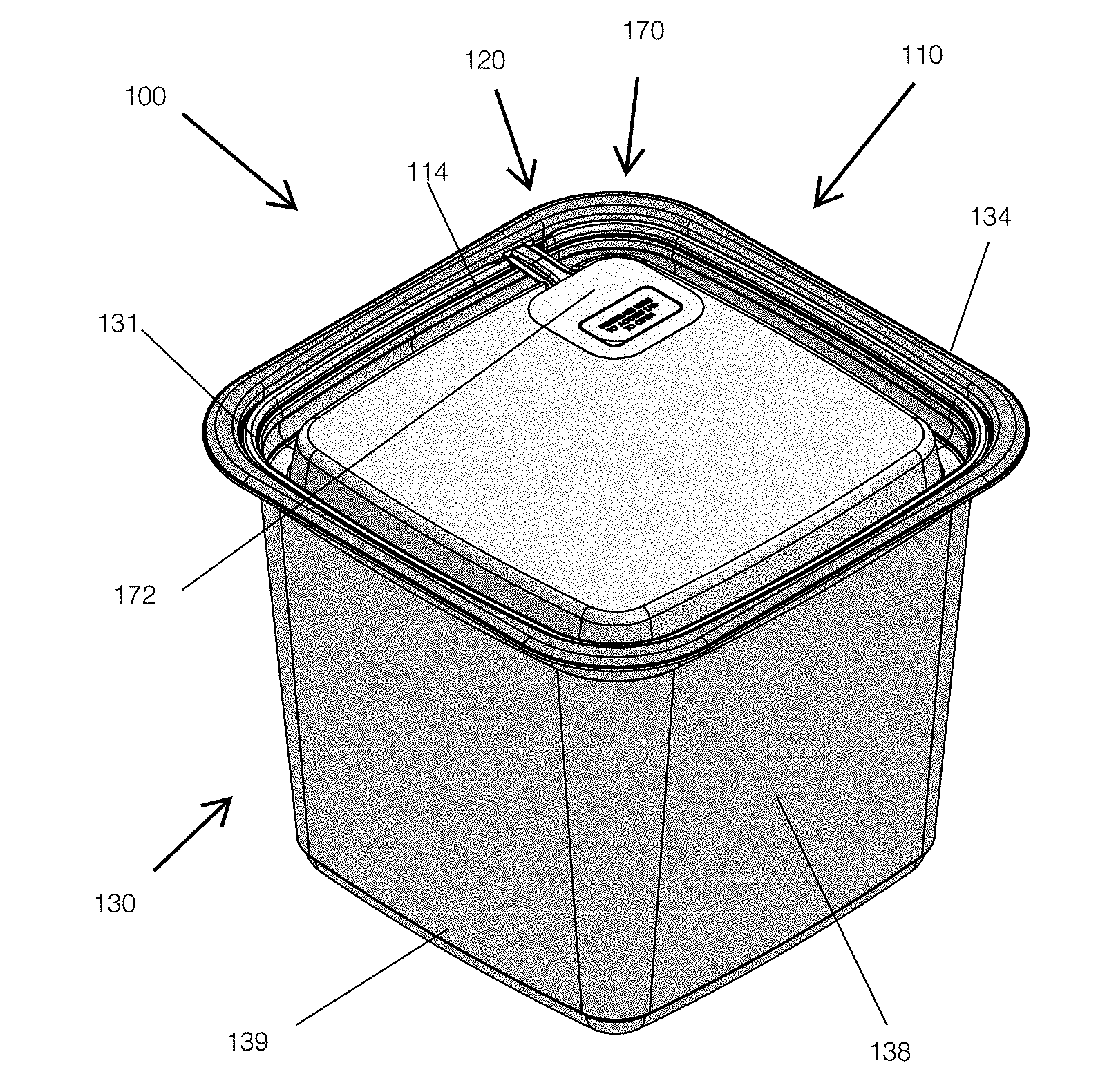
[0012] FIG. 1 illustrates a perspective view of a container with a tamper-evident feature.
[0013] FIG. 2A illustrates a perspective view of a lid of the container of FIG. 1 with a tab in an open position.
[0014] FIG. 2B illustrates a top view of a lid of the container of FIG. 1 with the tab in the open position.
[0015] FIG. 3 illustrates a top view of the container of FIG. 1.
[0016] FIG. 4 illustrates a section view taken along the line A-A in FIG. 3.
[0017] FIG. 5 illustrates detail C of FIG. 4.
[0018] FIG. 6 illustrates detail D of FIG. 4.
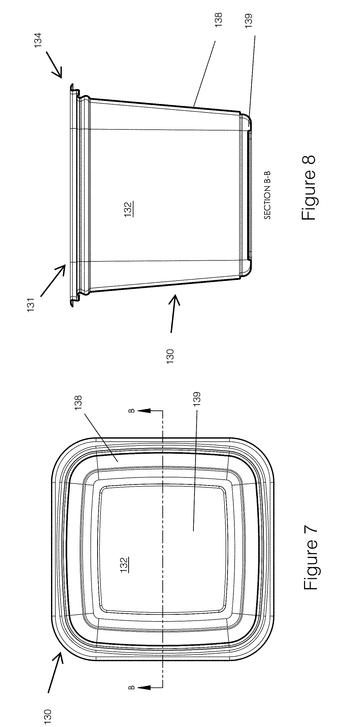
[0019] FIG. 7 illustrates a top view of a base of the container of FIG. 1.
[0020] FIG. 8 illustrates a section view taken along the line B-B in FIG. 7.
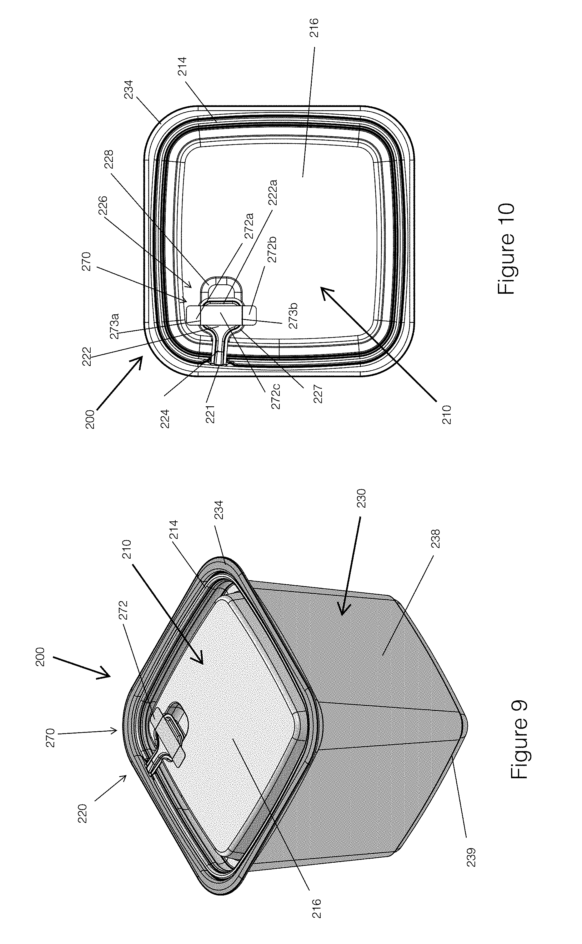
[0021] FIG. 9 is a perspective view of another embodiment of a container with a tamper-evident feature.
[0022] FIG. 10 is a top view of the container of FIG. 10.
[0023] FIG. 11 is a perspective view of another container.
[0024] FIG. 12 is a top view of the container of FIG. 11.
[0025] FIG. 13 is a section view of the container of FIG. 11.
[0026] FIG. 14 is a detail view of a portion of the container of FIG. 13.
[0027] FIG. 15 is a depiction of a tamper-evident feature that can be included in the container of FIG. 11, or otherwise.
[0028] FIG. 16 is another depiction of the tamper-evident feature shown in FIG. 15, with a tab in an open position.
DETAILED DESCRIPTION OF CERTAIN EMBODIMENTS
Overview
[0029] This disclosure relates to containers that can include tamper-proof or tamper-evident features. The technology of this disclosure may be applied to any type of container in which tamper-proof or tamper-evident features are beneficial. The container can include a lid and a base. The lid and base can couple together to form a closed container (e.g., a closed configuration). The closed container can comprise a sealed receptacle (e.g., a chamber) for receiving storable contents. In some variants, the receptacle is generally liquid or air tight. The closed container can be opened (e.g., an open configuration) to unseal the receptacle and allow access to the contents. For example, the lid can be removable from the base, such that the lid can be separated from the base to open the container. In some embodiments, the container can comprise discrete lid and base components. In some embodiments, the lid and base are hingedly connected, such that the lid can be pivoted relative to the base to open the container. For example, the container can comprise a clamshell container. In some embodiments, the lid and the base are separate components. The base can include a flange that can couple with the lid to close the container. The lid can fit within the flange of the base such that an outer periphery of the lid fits underneath a surface or protrusion of the flange. In some embodiments, the lid can be tightly fit within the flange of the base of the container. For example, the outer periphery can press outwardly against the flange. This configuration can prevent a user (e.g., a consumer) from easily removing the lid from the base to access the contents of the container by prying up a portion or side of the outer periphery of the lid.
[0030] To remove the lid from the base to obtain access to the contents of the container, the lid can include a tab. The tab can attach to the outer periphery of the lid. The tab can attach with the outer periphery at a hinge, such as a living hinge. The tab can be used to remove the lid. For example, in some embodiments, a user can grasp the tab, pull the tab away from the upper surface of the lid (e.g., by rotating the tab about the hinge), and use the tab to lift the lid apart from the base. In certain implementations, the tab is rotated and pulled relative to the base. For example, the tab can be rotated then pulled.
[0031] In some embodiments, the lid includes an indented region. The indented region can be configured to engage with the tab. For example, in some implementations, a portion of the tab (e.g., a head and/or neck of the tab) can be received in a recess of the indented region. In some embodiments, the recess can accommodate the tab such that the tab is generally flush with an upper surface of the lid in a closed configuration. In some implementations, the tab can be below the upper surface in the closed configuration.
[0032] The indented region can be configured to aid a user in accessing and/or grasping the tab. For example, the indented region can include a cavity that can be sized to accommodate the tip of a user's finger or thumb. The cavity can allow for a user to access, grasp, and/or pry (e.g., with a fingertip) underneath the head of the tab to lift the tab from the recess and/or away from the upper surface of the lid. This can facilitate removing the lid from the base of the container.
[0033] The lid can also include a tamper-evident feature. The tamper-evident feature can be an indicator overlaying at least a portion of the tab and/or the indented region. The indicator can be a strip (e.g., polymer, paper of other) attached to the upper surface of the lid. The indicator can go over all or a portion of the tab or indented region (e.g., cavity or recess). The indicator can cover and/or enclose the indented region (e.g., to prevent the buildup of dirt or debris). The indicator can inhibit or prevent a user from lifting the tab from the indented region without disturbing (e.g., tearing) the indicator. The container is configured such that, in order to access the tab and/or to pull the tab upward to remove the lid, a portion of the indicator is disturbed. For example, the user can push with their fingertip against the indicator where it covers the indented region, which can cause the indicator to break, thereby allowing the user's fingertip to enter at least partially into the indented region and grasp the tab. The broken indicator can provide lifting of the tab, which can alter and/or remove the indicator, or a part of the indicator, from its position on the lid or otherwise damage, tear, or alter the appearance of the indicator. In some embodiments, the indicator is damaged (e.g., torn) before the tab is moved relative to the lid. In certain variants, the indicator is damaged (e.g., torn) as the tab is moved relative to the lid. In some implementations, a tear is formed from a first side of the indicator to a second side of the indicator during movement of the tab relative to the lid and/or before the container is opened. The second side can be opposite the first side. In various embodiments, the indicator is irreversibly damaged (e.g., ruptured, torn, etc.) during opening of the container.
[0034] In some embodiments, the indicator may be a strip across a portion of the tab and/or the indented region. In some embodiments, the indicator can extend across the tab and leave the cavity uncovered to allow a user to lift the tab by inserting their finger into the cavity. In some embodiments, the indicator can include perforations. When the tab is lifted from the recess, the perforations can be torn and thereby provide an indication that the tab has been used.
[0035] The state of the indicator and/or tab can demonstrate that the tab has been removed from the indented region. For example, the indicator being ruptured and/or the tab being outside of the footprint of the base can indicate that the tab has been used to open the container. On the other hand, the indicator being intact (e.g., ruptured) and the tab is in the indented region can indicate that the contents of the container have not been accessed and/or adulterated.
[0036] The tab can be biased toward an opened or open position. In some embodiments, in the open position, the head of the tab is positioned outside of the outer periphery of the lid. This configuration can indicate that the container has been opened. Moreover, a biased tab can discourage or impede a user from opening the lid with the tab and then attempting to hide or obfuscate this act by replacing the tab within the indented region, since the tab will automatically move out of the indented region. A tab with a open position that is outside of the footprint of the base and/or the lid can facilitate stacking of multiple containers on top of each other without interference from the tab.
[0037] In various embodiments, the container includes multiple features that indicate whether the container has been opened. For example, in some embodiments, the location of the tab (e.g., in the cavity or not) and the state of the indicator (e.g., punctured or not) can each indicate whether the container has been opened. Thus, the container can provide multiple indications of the condition of the container to a user.
FIGS. 1-8
[0038] FIG. 1 illustrates a tamper-evident container 100. The container 100 can include a lid 110, a base 130, and a tamper-evident feature 170. The shape of the overall container 100 can be any suitable shape. For example, the shape of the container 100 when viewed from the top can be circular, oval, triangular, rectangular, hexagonal, or any other suitable shape (e.g., polygonal or other).
[0039] As shown in FIGS. 1, 7, and 8, the base 130 can include an opening 131 to a receptacle space 132. The receptacle space 132 can be configured for storage of an item or items (such as food, pharmaceuticals, or other items). As shown, the opening 131 can be on a top of the base 130. In some variants, the opening 131 is on a side or the bottom of the base 130.
[0040] The base 130 can be of any desirable shape. For example, as shown in FIG. 1, the base 130 can be generally rectangular. Other shapes are contemplated as well, such as circular, oval, triangular, square, hexagonal, or any other suitable shape (e.g., polygonal or other). The base 130 can include a plurality of sidewalls 138. A flange 134 can bound the opening 131 of the base 130. The flange 134 can be configured to couple the lid 110 to the base 130.
[0041] The lid 110 can be similarly shaped as the base 130 and/or can be configured to mate with the base 130. In some embodiments, the lid 110 can include an outer periphery 114. The outer periphery 114 can be configured to engage with the flange 134. Engagement of the outer periphery 114 and the flange 134 can removably couple together the lid 110 with the base 130. The shape of the outer periphery 114 can correspond to the shape of the flange 134 and/or the shape of the overall container 100 when viewed from the top.
[0042] As shown in FIG. 2A, the lid 110 can include a channel 113 and/or an upper surface 116. In some embodiments, the upper surface 116 can be generally planar. In some embodiments, the upper surface 116 can include one or more reinforcing ribs or channels. The upper surface 116 can be configured such that a label can be adhered thereto. For example, the label can indicate the contents of the container 100. The upper surface 116 can be raised with respect to a bottom surface of the channel 113a. A channel wall 115 can connect the upper surface 116 with the bottom wall 113a of the channel 113.
[0043] In some embodiments, the lid 110 can include an indented region 126. The indented region 126 can receive a tab 120. The indented region 126 can include a cavity 128. The cavity 128 can include a bottom surface 128a disposed below and offset from the upper surface 116. The cavity 128 can be configured to receive the tip of a user's finger or thumb. For example, the cavity 128 can include a width 128b that corresponds to the width of a thumb or finger of a user. In some embodiments, the width 128b can be between 1/4 inch to 1 inch wide, or more.
[0044] The indented region 126 can include a recess 127. The recess 127 can be at a lower elevation than, or offset with respect to, the upper surface 116. In certain variants, the recess 127 is at a higher elevation than a bottom 128a of the cavity 128. In some embodiments, the cavity 128 can have a width corresponding to the width 128b of the cavity 128. In certain implementations, the recess 127 can be wider than the cavity 128. As illustrated, in some embodiments, the recess 127 and the cavity 128 can intersect. In some variants, the indented region 126 comprises the recess 127 and the cavity 128.
[0045] The lid 110 can include the tab 120, which can be configured to facilitate removing the lid from the flange 134 of the base 130 and/or providing an indication of whether the container 100 can been opened. The tab 120 can be readily graspable by a user's fingers. The tab 120 can include a head 122 and neck 124. The tab and the neck 124 can be pivotally coupled with the lid 110. In some embodiments, the neck 124 can be coupled with an outer periphery 114 of the lid 110 at a hinge 121. In some embodiments, the hinge 121 can be a living hinge. The hinge 121 can comprise the material of the lid 110. The hinge 121 can be coupled with the outer periphery 114 of the lid 110. The hinge 121 can be generally aligned with the recess 127 and/or the cavity 128. For example, a line can be passed through the head 122, neck 124, recess 127, and cavity 128.
[0046] The tab 120 can be configured to lay generally flush with the upper surface 116 or below the upper surface 116. For example, the head 122 of the tab 120 can rest at least partially within the recess 127. An upper edge 122a of the head 122 can extend into the cavity 128. For example, the upper edge 122a of the head 122 can overlap, overhang, and/or be cantilever into cavity 128. This can enable a user to insert a fingertip into the cavity 128 to easily grasp the edge 122a of the head 122 and/or to lift the tab 120 from the indented region 126. For example, the tab 120 can be moved from the closed position shown in FIG. 1 to the open position shown in FIG. 2A. In some embodiments, in the open position, the tab 120 is positioned outside of the outer periphery 114 of the lid 110.
[0047] The tab 120 can be biased towards the open position. The tab 120 can be formed as a portion of the outer periphery 114 of the lid 110 (e.g., the tab 120 can be formed integrally with the lid 110). The tab 120 can extend outwardly from the outer periphery 114 of the lid 110 when formed (e.g., by molding of the plastic or other material). The tab 120 can then be placed into tension when rotated into the closed position (e.g., within the indent 126). Thus, when unconstrained (e.g., in the rest or opened positions after the container is opened by a user) the tab can have a natural tendency to extend outwardly from the outer periphery 114 of the lid 110.
[0048] The neck 124 can be flexible and/or resilient. For example, the neck 124 can be made from a flexible polymer and/or can be thin enough to allow for bending and twisting of the head 122 with respect to the upper surface 116, such as about the hinge 121. In some embodiments, the flexibility of the neck 124 can inhibit or prevent breakage or tearing of the hinge 121. For example, during movement of the tab 120 between the closed and open positions, the tab 120 may be bent and/or twisted, which can be accommodated by the flexible neck 124. The neck 124 can be configured to flex or bend such that the tab 120 does not easily break off or separate from the outer periphery 114. For example, the tab 120 can be configured to move between the closed and open positions at least once, twice, three times, or more without breaking. In some embodiments, the neck 124 can be the same width as the head 122. In certain embodiments, the neck 124 can be substantially narrower than the width of the head 122. This can provide the advantage of using less material and creating a lower footprint on the upper surface 116 of the lid 110. The neck 124 can form a bridge between the hinge 121 at the outer periphery 114 and the recess 127 of the indented region 126 (e.g., over the channel 113). In some embodiments, the neck 124 can provide a location for a user to grasp and move (e.g., rotate and/or pull) the tab 120 about the hinge 121.
[0049] The head 122 can have a width 120b that is measured parallel to the width 128b of the cavity 128. In some embodiments, the width 120b of the head 122 can generally correspond to, or be greater than, the width of a fingertip of a user. The tab 120 can have a length 120a that is measured from the hinge 121 to the outer edge 122a of the head 122. The length 120a can be any suitable length. In some embodiments, the length 120A is between 0.5 inches and 1.5 inches, or more. As illustrated, in some embodiments, the tab 120 can be substantially T-shaped between the head 122 and the neck 124. The head 122 can be configured (e.g., sized and shaped) to be received in the recess 127 of the lid 110.
[0050] Referring to FIGS. 1 and 3, the container 100 can include the tamper-evident feature 170. In some implementations, the tamper-evident feature 170 comprises the tab 120, such as the location of the tab 120 (e.g., in the open or closed position). In some embodiments, the tamper-evident feature 170 comprises an indicator 172. The indicator 172 can be a strip attached to the upper surface 116 of the lid 110. The indicator 172 can be made from any suitable material, such as polymers, papers, resin, stickers, labels, tape or other sheet-like materials. The indicator 172 can be adhered to the upper surface 116 using any suitable adhesive, such as epoxies, polyurethane, polyvinyl acetate, plastics, and cyanoacrylates. In some embodiments, the indicator 172 comprises tape or a sticker.
[0051] The indicator 172 can overlay some or all of the recess 127 and/or cavity 128. The indicator 172 can cover some or all of the head 122 and/or a portion of the neck 124 of the tab 120. An outer periphery 172a of the indicator 172 can be sealed against the upper surface 116 of the lid 110, such as with adhesive. In some embodiments, the indicator 172 can overlap at least a portion of the cavity 128 and/or the recess 127. In some embodiments, the indicator 172 covers the head 122 or a portion of the head 122. The indicator 172 can cover the top edge 122a of the head 122.
[0052] The indicator 172 can be configured to change state in response to accessing and/or movement of the tab 120. In some implementations, for a user to be able to pull up the tab 120 from within the indented region 126, the user must change the state of the indicator 172 (e.g., permanently). For example, to grasp the upper edge 122a of the head 122 that overhangs the cavity 128, the user must press against and rupture a portion of the indicator 172. In some implementations, the rupture occurs by tearing a central portion or of the indicator 172. In some implementations, the rupture occurs by moving one or more portions of the outer edge 172a (e.g., lifting the outer edge 172a from the upper surface 116). The rupture of the indicator 172 can provide a visual indicator that the container 100 has been tampered with. The tamper-evident feature 170 can provide a warning that the container 100 may have been opened and/or the contents accessed. This could signal that the container 100 should be avoided or discarded because of the potential for adulterated contents. The indicator 172 can include indicia (e.g., text) to provide instructions and/or indicate the purpose of the indicator 172 and the implications of a change of state. For example, the indicator 172, and/or other portions of the container 100, can instruct a user how to remove the lid, such as by penetrating the indicator 172, to access the tab 120 in order to open the lid 110. In addition, the text can include instructions for what to do with the container 100 if the indicator 172 suggests that the container 100 has been opened, such as an instruction to discard the container and to not use the contents. In some embodiments, the change of state of the indicator occurs in response to accessing the tab 120. In certain variants, the change of state of the indicator occurs before the tab 120 is moved relative to the lid 110.
[0053] In some embodiments, the indicator 172 can include frangible portions or perforations. This can facilitate penetrating the indicator 172, such as with a finger into the cavity 128. Breakage of the frangible or perforated portions can provide visual evidence that the indicator 172 has been tampered with. In some embodiments, the frangible portion and/or indicator 172 can define a sub-portion of the indicator that can easily be torn out by a user inserting their finger through the indicator 172. This frangible or portion defined by the perforations can be placed in a manner adjacent to the upper edge 122a of the head 122 of the tab 120. In certain embodiments, the frangible portion or the perforations can correspond to (e.g., follow) a profile of the cavity 128.
[0054] In certain embodiments, the user may grasp the head 122, such as to rotate and/or pull the tab 120 relative to the base 130. For example, in various implementations, the tab 120 can be rotated first and pulled second, pulled first and rotated second, or pulled and rotated concurrently. In some implementations, the user may grasp the neck 124 and rotate and/or pull (e.g., up) on the neck 124, such as to rotate the tab 120 about the hinge 121. When the user grasps the neck 124 instead of grasping the head 122, the indicator 172 can be damaged by movement of the tab 120 and thereby provide an indication of the tampering. For example, movement of the tab 120 relative to the indicator 172 can tear or otherwise damage a portion of the indicator 172. In some implementations, a user grasping the neck 124 may break the neck from the hinge 121, thereby providing another indication of the tampering. For example, because the neck 124 is fixed to the head 122 and the head 122 is fixed with respect to the upper surface 116 by the indicator 172, a user attempting to lift the tab 120 by the neck 124 can stress the hinge 121 and cause it to break or tear. In this manner, the lid 110 can provide evidence of tampering where a user has not directly crumpled or torn the indicator 172 but rather the hinge 121 and neck 124.
[0055] FIG. 4 illustrates a section view taken of the container 100. Detailed views of the interface of the lid 110 with the flange 134 are shown in FIGS. 5 and 6. The flange 134 of the base 130 can extend from the plurality of container walls 138. The flange 134 can include a peripheral channel 135. The peripheral channel 135 can aid in retaining the lid 110 within the opening 131 of the base 130. The peripheral channel 135 can be configured to engage with a corresponding circumferential protrusion 117 of the lid 110. The protrusion 117 can be disposed around the outer periphery 114 of the lid 110. The protrusion 117 can be engaged within the peripheral channel 135 when the lid 110 is fixed within the opening 131 and thereby removably engaged with the base 130. In other implementations, the base 130 can include the protrusion and the lid 110 can include the peripheral channel for receiving the protrusion.
[0056] The flange 134 can include an upper lip 137. The upper lip 137 of the flange 134 can extend above the angled panel 136 such that the outer periphery of the lid 110 can be disposed beneath and/or hidden under the upper lip 137 of the flange 134. This can inhibit or prevent, and/or discourage, a user from removing the lid 110 from the flange 134 by lifting or prying one edge of the lid 110. Instead, it encourages the user to use the tab 120 to open the container 100. The upper lip 137 can include an angled panel 136. The angled panel 136 can be angled towards a center of the container 100. The angled panel 136 can be angled inwardly such that a portion of the outer periphery 114 engages with the angled panel 136 when the lid 110 is attached with the flange 134. For example, an outer edge 114a can be engaged with or underneath the angled panel 136. Once the outer edge 114a is removed from underneath the angled panel 136, the lid 110 can be easily removed from the opening 131.
[0057] The channel 113 and/or other portions of the outer periphery 114 can provide an outward force on the flange 134 (e.g., against the concave peripheral channel 135 and/or the angled panel 136). This outward force, and/or a physical interference between parts of the lid 110 and parts of the base 130, can secure the lid 110 with the flange 134. In some embodiments, removal of the lid 110 from the flange 134 requires compression of the outer periphery 114 on multiple sides, which can be difficult for a user and may dissuade tampering with the container 100 in this manner.
[0058] As mentioned above, the container 100 can be configured to inhibit or prevent a user from inserting their finger underneath the outer edge 114a of the outer periphery 114, thereby prying up the lid 110 from the flange 134 in order to access the receptacle space 132. The tab 120 makes removal of the lid 110 much easier by providing a handle for prying up one side of the outer periphery 114. This can be by acting as a lever to move (e.g., compress inward) the portion of the outer edge 114a such that it can pass over the angled panel 136 and/or the panel concave peripheral channel 135. In some embodiments, the tab 120 can be pulled directly upwards, which can overcome the friction and the force exerted by the outer periphery 114 that contains it within the flange 134 (e.g., within the concave peripheral channel 135 and the angled portion panel 136).
FIGS. 9 and 10
[0059] FIGS. 9 and 10 illustrate another embodiment of a tamper-evident container 200. The tamper-evident container 200 can include any of the structure or other features described above in connection with the container 100. For example, the container 200 can include a base 230 and a lid 210 that can be similar to the base 130 and lid 110.
[0060] The outer periphery 214 of the lid 210 is disposed within a flange 234 of the base 230. The flange 234 can removably couple the lid 210 with the base 230. As previously described, the container 200 can be configured to inhibit or prevent an edge of the lid 210 from being grasped to lift the lid 210 out of the base 230.
[0061] The lid 210 can include a tab 220. The tab 220 can include a hinge 221, neck 224, and a head 222. The head 222 can be disposed within an indented region 226. The indented region 226 can include a recess 227 and/or a cavity 228. The indented region 226 can be configured to receive a portion of the tab 220. In some embodiments, when received in the indented region 226, the tab 220 can be generally flush with and/or at an elevation below an upper surface 216 of the lid 210. The lid 210 can be removed from the flange 234 by a user lifting up the head 222 from the indented region 226 and pivoting the head 222 and the neck 224 about the hinge 22. The tab 220 can provide a handle for a user to pry a portion of the outer periphery 214 of the lid 210 from the flange 234. The lid 210 can then be easily removed from the flange 234.
[0062] The lid 210 can include a tamper-evident feature 270. The tamper-evident feature 270 can include an indicator 272. The indicator 272 can include first and second ends 272a, 272b. First and second ends 272a, 272b can include adhesive such as adhesives described above in relation to the indicator 172. The first and second ends 272a, 272b can be adhered or otherwise affixed to the upper surface 216 of the lid 210. A central portion 272c of the indicator 272 can have no adhesive, in some embodiments. In other embodiments, the central portion 272c can be adhered to the tab 220. The indicator 272 can extend across the tab 220. For example, the indicator 272 can extend across the head 222 and/or the neck 224 of the tab 220. In some embodiments, the indicator 272 does not extend across the cavity 228, leaving the cavity 228 open for a user to grasp the tap 220. Lifting of the tab 220 can damage (e.g., tear) the indicator 272 and thereby indicate that the container 200 has potentially been opened. In some embodiments, lifting the tab 220 separates the central portion 272c from the first and/or second ends 272a, 272b.
[0063] In some embodiments, the indicator 272 can include one or more perforations or frangible portions 273. The frangible perforations 273 can tear off when a user pulls up on the tab 220. This can provide indication that the contents of the container have been contaminated or accessed.
FIGS. 11-16
[0064] FIGS. 11-16 illustrate another embodiment of a tamper-evident container 300. The tamper-evident container 300 illustrated is for enclosing a pie, however, the technology of this disclosure is not limited to only pie containers. Rather, as indicated above, the technology of this disclosure may be applied to most any type of container in which tamper-evident features are beneficial. The tamper-evident container 300 can include any of the structure or other features described above in connection with the containers 100 or 200. For example, the container 300 can include a base 330 and a lid 310 that can be similar to the base 130 and lid 110. The container 300 can have various shapes, such as circular, oval, hexagonal, octagonal, rectangular, triangular, star-shaped, or any other regular or irregular shape.
[0065] In various embodiments, an outer periphery 314 of the lid 310 is disposed within a flange 334 of the base 330. The flange 334 can provide a radial and/or axial interference with the outer periphery 314 of the lid 310. The flange 334 can secure together and/or removably couple the lid 310 with the base 330. As previously described, the container 300 can be configured to inhibit or prevent an edge of the lid 310 from being grasped to lift the lid 310 out of the base 330.
[0066] The lid 310 can include a tab 320. The tab 320 can include any of a hinge, neck, and a head. In a first state (e.g., a locked or closed state), the head can be disposed within an indent 326. The indent 326 can include a cavity and/or recess, as described above. The indent 326 can be configured to receive a portion of the tab 320. In some embodiments, when received in the indent 326, the tab 320 can be generally flush with and/or at an elevation below a surface (e.g., a side or upper surface) of the lid 310. The lid 310 can be removed from the flange 334 by a user moving the tab 320 out of the indent 326. For example, the tab 320 can be grasped, lifted-up, pried, or otherwise moved. The tab 320 can provide a handle for a user to grasp. In some embodiments, the tab 320 enables a user to pull or otherwise remove a portion of the outer periphery 314 of the lid 310 from the flange 334 of the base 330. The lid 310 can then be easily removed from the base 330. The indent 326 can be in a horizontal surface of the lid 310 or in a vertical or partially vertical surface of the lid 310, as illustrated in FIG. 11.
[0067] As shown in FIG. 14, in some embodiments, an end 329 of the tab 320 can be spaced apart from a wall 331 of the lid 310. For example, an upper end of the tab 320 can grasp and/or move the tab 320 relative to the wall 331.
[0068] The lid 310 can include a tamper-evident feature 370. The tamper-evident feature 370 can include an indicator 372. The indicator 372 can include adhesive, such as adhesives described above in relation to the indicator 172. The indicator 372 can be adhered or otherwise affixed to the surface of the lid 310. A central portion of the indicator 372 can have no adhesive, in some embodiments. In other embodiments, the central portion can be adhered to the tab 320. In certain embodiments, the indicator 372 extends across substantially the entire indent 326, as illustrated by the dashed line in FIG. 11. The indicator 372 can extend across the tab 320. In some embodiments, the indicator 372 does not extend across the indent 326, leaving the indent 326 open for a user to grasp the tab 320. Lifting of the tab 320 can damage (e.g., tear) the indicator 372 and thereby indicate that the container 300 has potentially been opened. In some embodiments, the container 300 is configured such that, in order to access the tab 320, a user must puncture the indicator 372, such as with a fingertip. The punctured indicator 372 can show that the tab 320 has been accessed and thus that the container 300 may have been opened.
[0069] In some embodiments, the indicator 372 can include one or more perforations or frangible portions. The frangible perforations can tear off when a user pulls up on the tab 320. This can provide indication that the contents of the container 300 have been contaminated or accessed.
Certain Terminology
[0070] Terms of orientation used herein, such as "top," "bottom," "horizontal," "vertical," "longitudinal," "lateral," and "end" are used in the context of the illustrated embodiment. However, the present disclosure should not be limited to the illustrated orientation. Indeed, other orientations are possible and are within the scope of this disclosure. Terms relating to circular shapes as used herein, such as diameter or radius, should be understood not to require perfect circular structures, but rather should be applied to any suitable structure with a cross-sectional region that can be measured from side-to-side. Terms relating to shapes generally, such as "circular" or "cylindrical" or "semi-circular" or "semi-cylindrical" or any related or similar terms, are not required to conform strictly to the mathematical definitions of circles or cylinders or other structures, but can encompass structures that are reasonably close approximations.
[0071] Some embodiments have been described in connection with the accompanying drawings. The figures are drawn to scale where appropriate, but such scale should not be limiting, since dimensions and proportions other than what are shown are contemplated and are within the scope of the disclosed invention. Distances, angles, etc. are merely illustrative and do not necessarily bear an exact relationship to actual dimensions and layout of the devices illustrated. Components can be added, removed, and/or rearranged. Further, the disclosure herein of any particular feature, aspect, method, property, characteristic, quality, attribute, element, or the like in connection with various embodiments can be used in all other embodiments set forth herein. Additionally, any methods described herein may be practiced using any device suitable for performing the recited steps.
[0072] The terms "approximately," "about," and "substantially" as used herein represent an amount close to the stated amount that still performs a desired function or achieves a desired result. For example, in some embodiments, as the context may permit, the terms "approximately", "about", and "substantially" may refer to an amount that is within less than or equal to 10% of the stated amount. The term "generally" as used herein represents a value, amount, or characteristic that predominantly includes or tends toward a particular value, amount, or characteristic. As an example, in certain embodiments, as the context may permit, the term "generally parallel" can refer to something that departs from exactly parallel by less than or equal to 20 degrees.
Summary
[0073] Although this invention has been disclosed in the context of certain embodiments and examples, the scope of this disclosure extends beyond the specifically disclosed embodiments to other alternative embodiments and/or uses of the invention and obvious modifications and equivalents thereof. Any system, method, and device described in this application can include any combination of the preceding features described in this and other paragraphs, among other features and combinations described herein, including features and combinations described in subsequent paragraphs. While several variations of the invention have been shown and described in detail, other modifications, which are within the scope of this invention, will be readily apparent to those of skill in the art based upon this disclosure. It is also contemplated that various combinations or sub-combinations of the specific features and aspects of the embodiments may be made and still fall within the scope of the invention. Various features and aspects of the disclosed embodiments can be combined with, or substituted for, one another in order to form varying modes of the disclosed invention. Thus, it is intended that the scope of the present invention herein disclosed should not be limited by the particular disclosed embodiments described above, but should be determined only by a fair reading of the claims that follow.
* * * * *
D00000
D00001
D00002
D00003
D00004
D00005
D00006
D00007
D00008
D00009
XML
uspto.report is an independent third-party trademark research tool that is not affiliated, endorsed, or sponsored by the United States Patent and Trademark Office (USPTO) or any other governmental organization. The information provided by uspto.report is based on publicly available data at the time of writing and is intended for informational purposes only.
While we strive to provide accurate and up-to-date information, we do not guarantee the accuracy, completeness, reliability, or suitability of the information displayed on this site. The use of this site is at your own risk. Any reliance you place on such information is therefore strictly at your own risk.
All official trademark data, including owner information, should be verified by visiting the official USPTO website at www.uspto.gov. This site is not intended to replace professional legal advice and should not be used as a substitute for consulting with a legal professional who is knowledgeable about trademark law.