Distance Adjustment Mechanism For Fence Assembly Of Table Saw
Chang; Chin-Chin
U.S. patent application number 16/214054 was filed with the patent office on 2019-04-11 for distance adjustment mechanism for fence assembly of table saw. The applicant listed for this patent is Chin-Chin Chang. Invention is credited to Chin-Chin Chang.
| Application Number | 20190105797 16/214054 |
| Document ID | / |
| Family ID | 65992908 |
| Filed Date | 2019-04-11 |


View All Diagrams
| United States Patent Application | 20190105797 |
| Kind Code | A1 |
| Chang; Chin-Chin | April 11, 2019 |
DISTANCE ADJUSTMENT MECHANISM FOR FENCE ASSEMBLY OF TABLE SAW
Abstract
A fence assembly of a table saw includes rear and front sliding members slidably disposed on two rails of a table respectively, the rear sliding member having three equally spaced top projections, the front sliding member having three equally spaced forward projections, a transverse member interconnecting the sliding members, and a spring biased workpiece guide bar on the transverse member. The workpiece guide bar includes a front locking element for locking the workpiece guide bar on the front sliding member, a rear locking element for locking the workpiece guide bar on the rear sliding member, the rear positioning element having a recess for receipt of the top projection, and a spring biased lever pivotably secured to the workpiece guide bar. A latch of the lever can be engaged with a protuberance of the front locking element to lock the workpiece guide bar or disengaged from the protuberance to unlock same.
| Inventors: | Chang; Chin-Chin; (Taichung City, TW) | ||||||||||
| Applicant: |
|
||||||||||
|---|---|---|---|---|---|---|---|---|---|---|---|
| Family ID: | 65992908 | ||||||||||
| Appl. No.: | 16/214054 | ||||||||||
| Filed: | December 8, 2018 |
Related U.S. Patent Documents
| Application Number | Filing Date | Patent Number | ||
|---|---|---|---|---|
| 15455136 | Mar 10, 2017 | 10183415 | ||
| 16214054 | ||||
| Current U.S. Class: | 1/1 |
| Current CPC Class: | B23D 47/025 20130101; B27B 27/02 20130101; B27B 27/10 20130101 |
| International Class: | B27B 27/10 20060101 B27B027/10 |
Claims
1. A table saw comprising: a table assembly including a table and two rails on front and rear ends of the table respectively; a base assembly for supporting the table assembly; a saw assembly disposed on the table assembly; a height adjustment assembly disposed on a front surface of the base assembly; and a fence assembly including rear and front sliding members slidably disposed on the rails respectively, the rear sliding member having three equally spaced top projections, the front sliding member having three equally spaced forward projections, a transverse member interconnecting the distal ends of the sliding members, and a workpiece guide bar disposed on the transverse member; wherein the workpiece guide bar is spring biased and pivotably secured to a rear end of the workpiece guide bar; wherein the workpiece guide bar includes a front locking element configured to lock the workpiece guide bar on the front sliding member, a rear locking element configured to lock the workpiece guide bar on the rear sliding member, the rear positioning element having a horizontally forward recess for complimentary receipt of the top projection, the front positioning element having a vertically downward recess for complimentary receipt of the forward projection and a spring biased lever pivotably secured to a front end of the workpiece guide bar, the lever having a latch; and wherein in a first position, the latch is disengaged from a protuberance of the front locking element, the front locking element is unlocked, and the rear and front locking elements are configured to unlock the workpiece guide bar on the rear and front sliding members respectively; and wherein in a second position, the latch is engaged with the protuberance, the front locking element is locked, and the rear and front locking elements are configured to lock the workpiece guide bar on the rear and front sliding members respectively.
2. The table saw of claim 1, wherein the workpiece guide bar further comprises a pivotal side plate on an outer surface, the side plate having two protrusions on two ends respectively, the protrusions configured to releasably secure to two cavities on an outer surface of the workpiece guide bar respectively.
3. The table saw of claim 1, further comprising a tab on a bottom of the support member for supporting the rear sliding member.
4. The table saw of claim 1, wherein the rear end of the workpiece guide bar and the rear positioning element are resiliently connected together.
5. The table saw of claim 1, wherein the front positioning element is secured to an inner surface of the workpiece guide bar.
Description
CROSS-REFERENCE TO RELATED APPLICATION
[0001] This application is a continuation-in-part (CIP) of U.S. patent application Ser. No. 15/455,136, filed Mar. 10, 2017, which is incorporated herein by reference in its entirety.
BACKGROUND OF THE INVENTION
1. Field of the Invention
[0002] The invention relates to table saws and more particularly to a fence assembly having a mechanism for adjusting a distance between itself and a saw assembly of a table saw.
2. Description of Related Art
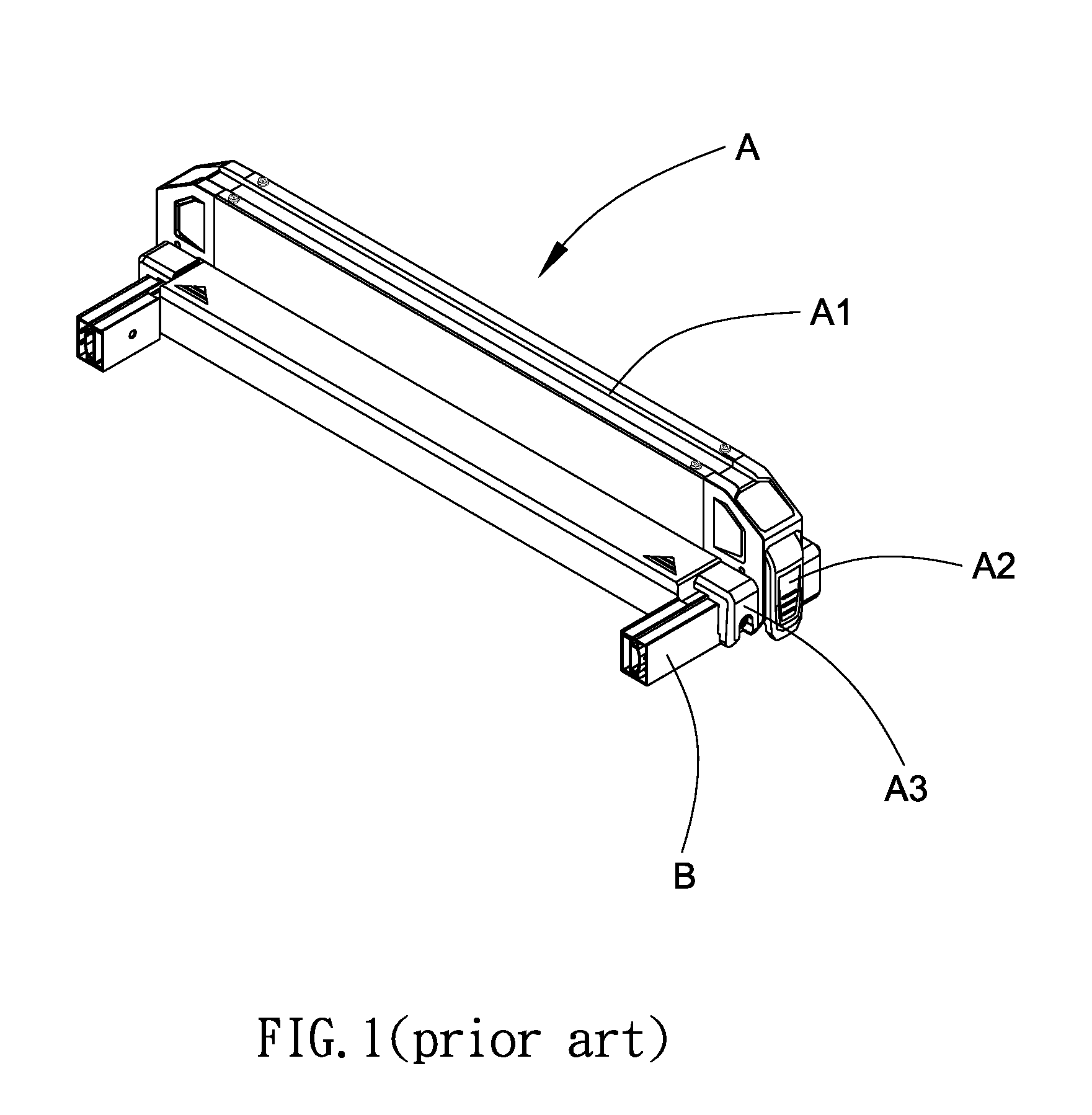
[0003] A conventional fence assembly A of a table saw is shown in FIGS. 1 and 2 and includes a transverse bar A1, two levers A2 at two ends of the bar A1 respectively, and two U-shaped openings A3 each secured to an end of the bar A1. Each U-shaped opening A3 is adapted to lockingly receive one of two lengthwise rails B.
[0004] In a positioning operation, a user has to manually operate the levers A2 to lock the lengthwise rails B respectively. However, the user may cross the table of the table saw to operate the levers A2 for locking and this operation is not convenient.
[0005] Thus, the need for improvement still exists.
SUMMARY OF THE INVENTION
[0006] It is therefore one object of the invention to provide a table saw comprising a table assembly including a table and two rails on front and rear ends of the table respectively; a base assembly for supporting the table assembly; a saw assembly disposed on the table assembly; a height adjustment assembly disposed on a front surface of the base assembly; and a fence assembly including rear and front sliding members slidably disposed on the rails respectively, the rear sliding member having three equally spaced top projections, the front sliding member having three equally spaced forward projections, a transverse member interconnecting the distal ends of the sliding members, and a workpiece guide bar disposed on the transverse member; wherein the workpiece guide bar is spring biased and pivotably secured to a rear end of the workpiece guide bar; wherein the workpiece guide bar includes a front locking element configured to be locked on the front sliding member, a rear locking element configured to be locked on the rear sliding member, the rear locking element having a recess for complimentary receipt of the top projection, and a spring biased lever pivotably secured to a front end of the workpiece guide bar, the lever having a latch; and wherein in a first position, the latch is disengaged from a protuberance of the front locking element, the front locking element is unlocked, and the rear and front locking elements are configured to unlock the workpiece on the rear and front sliding members respectively; and wherein in a second position, the latch is engaged with the protuberance, the front locking element is locked, and the rear and front locking elements are configured to lock the workpiece on the rear and front sliding members respectively.
[0007] The above and other objects, features and advantages of the invention will become apparent from the following detailed description taken with the accompanying drawings.
BRIEF DESCRIPTION OF THE DRAWINGS
[0008] FIG. 1 is a perspective view of a conventional fence assembly of a table saw;
[0009] FIG. 2 is an exploded view of the fence assembly to show how to manually operate the levers to lock the lengthwise rails respectively;
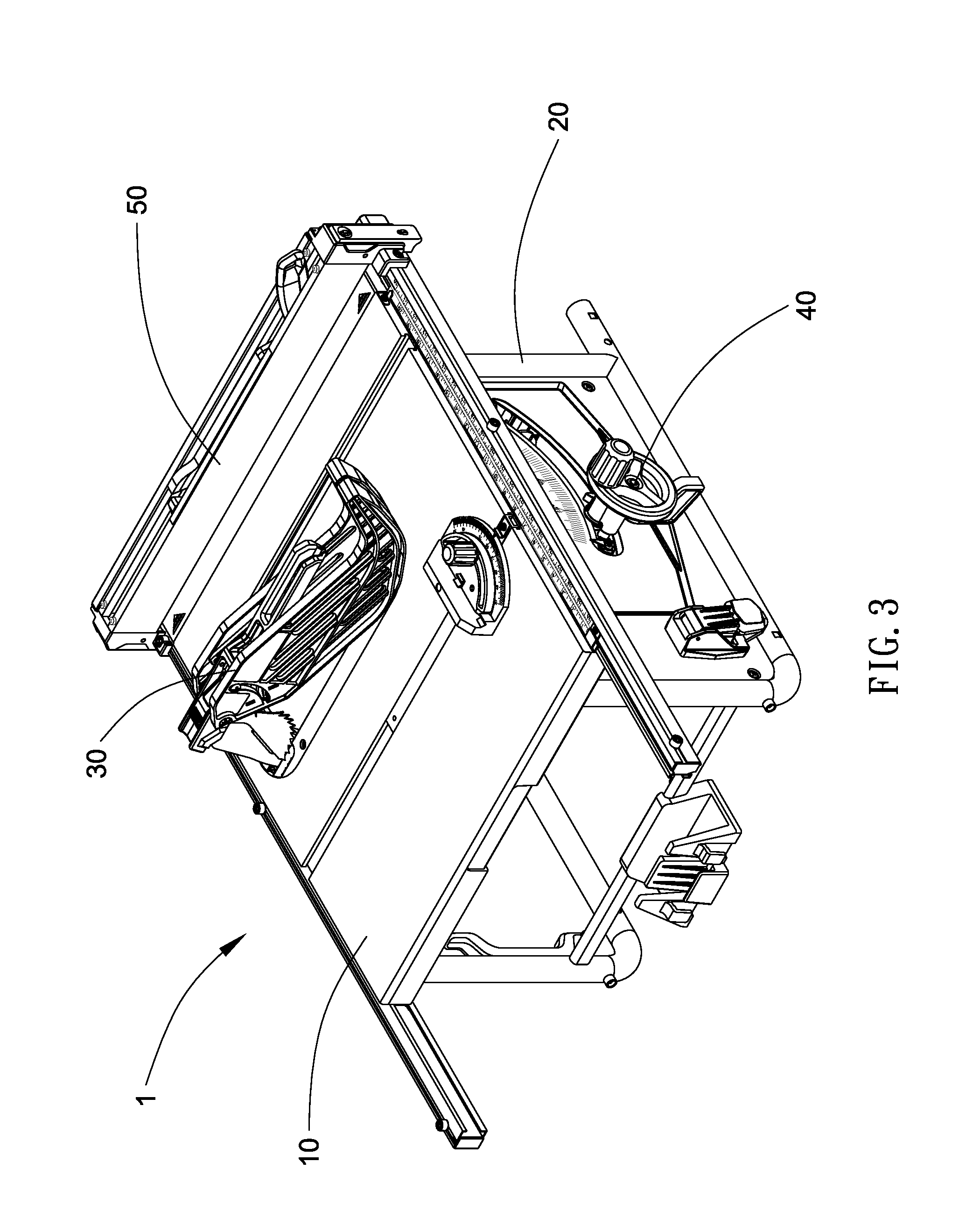
[0010] FIG. 3 is a perspective view of a table saw incorporating a distance adjustment mechanism for a fence assembly according to the invention;
[0011] FIG. 4 is a view similar to FIG. 3 showing the fence assembly being slid laterally about the rails;
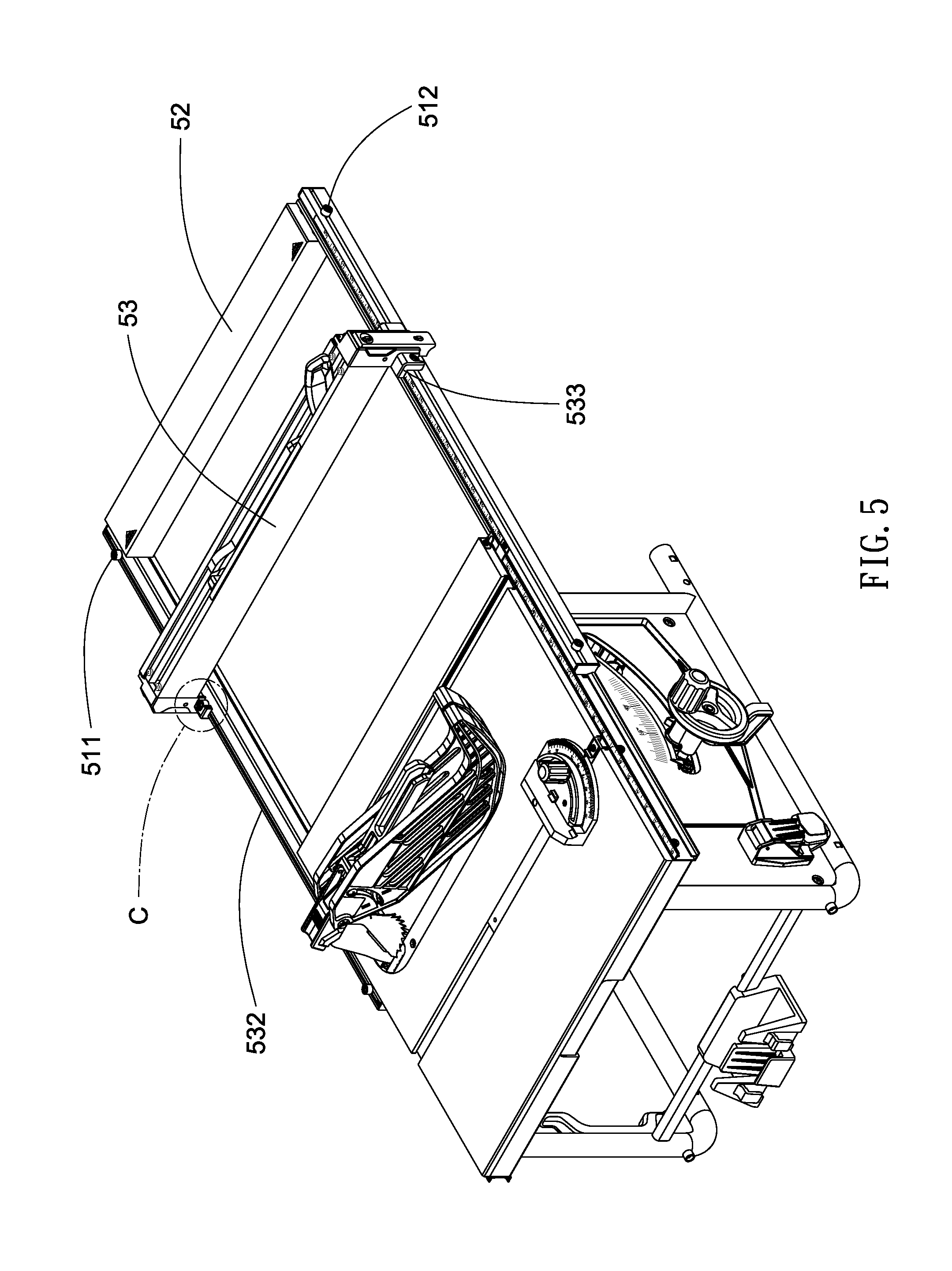
[0012] FIG. 5 is a view similar to FIG. 4 showing the fence assembly being removed and adjusted to position the transverse bar with respect to the locking elements toward the saw assembly;
[0013] FIG. 6 is a detailed view of the area in circle C of FIG. 5;
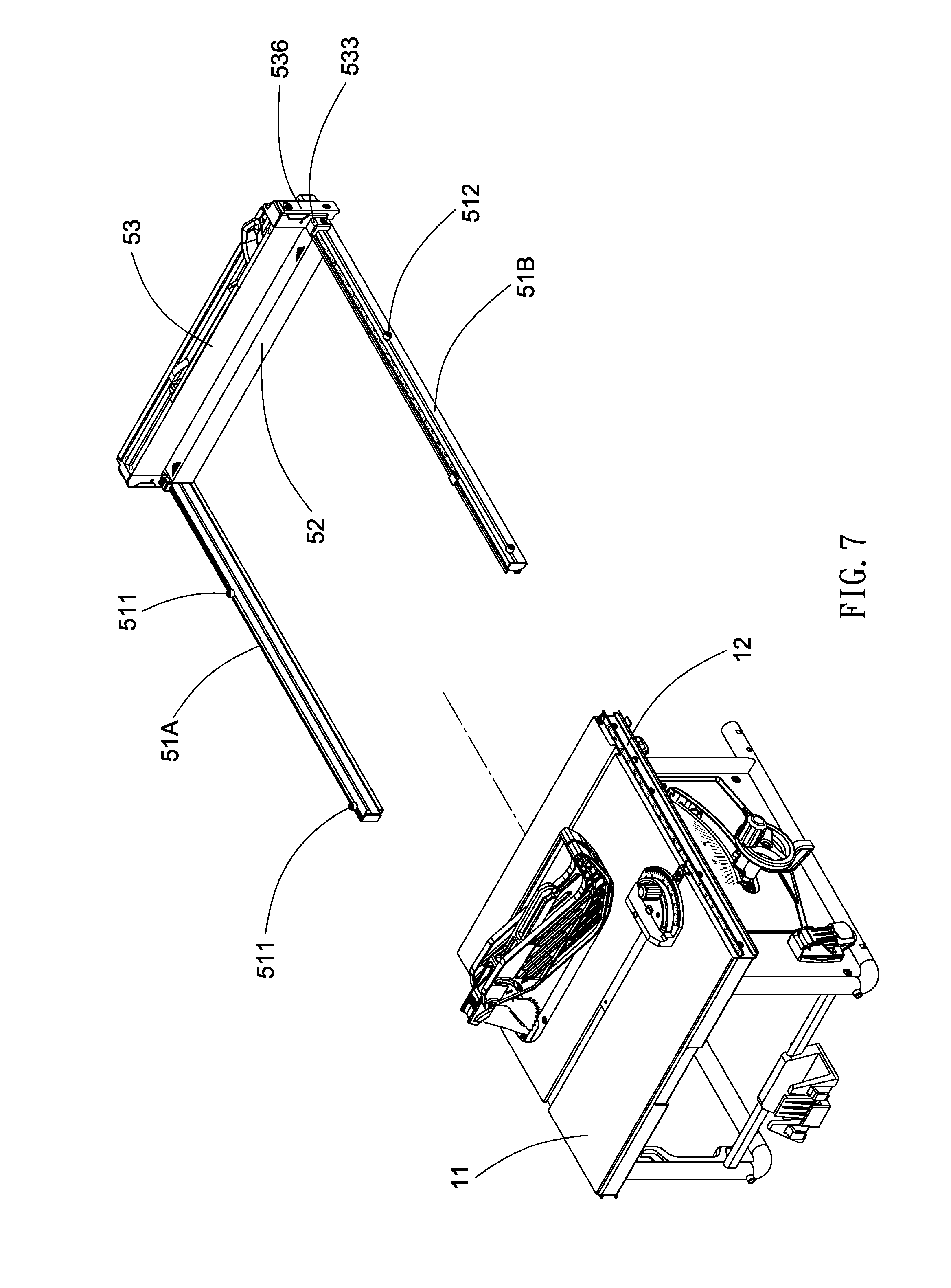
[0014] FIG. 7 is a perspective view showing the fence assembly being detached from the table saw;
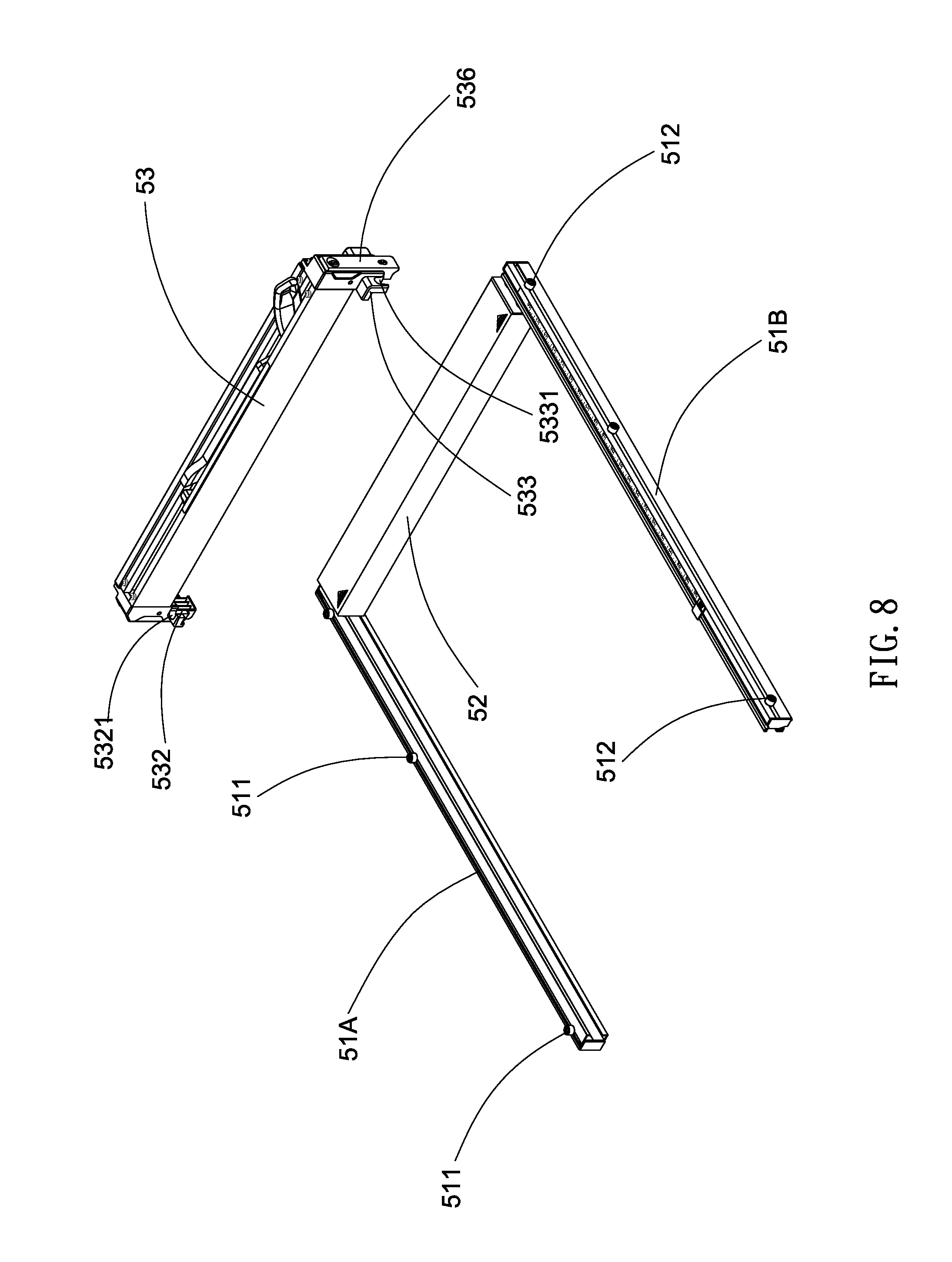
[0015] FIG. 8 is an exploded perspective view of the fence assembly;
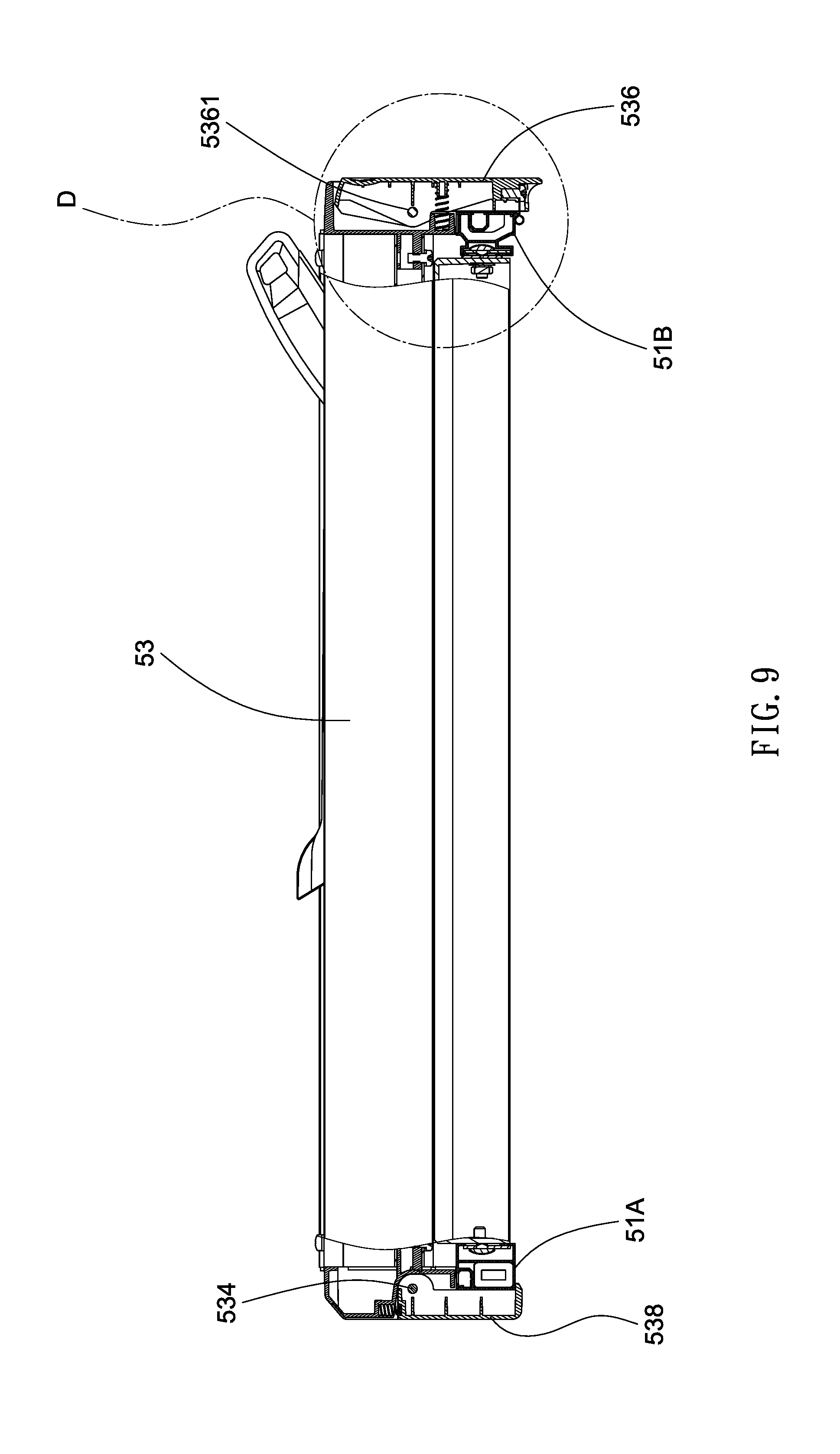
[0016] FIG. 9 is a longitudinal sectional view of the fence assembly where the lever is locked;
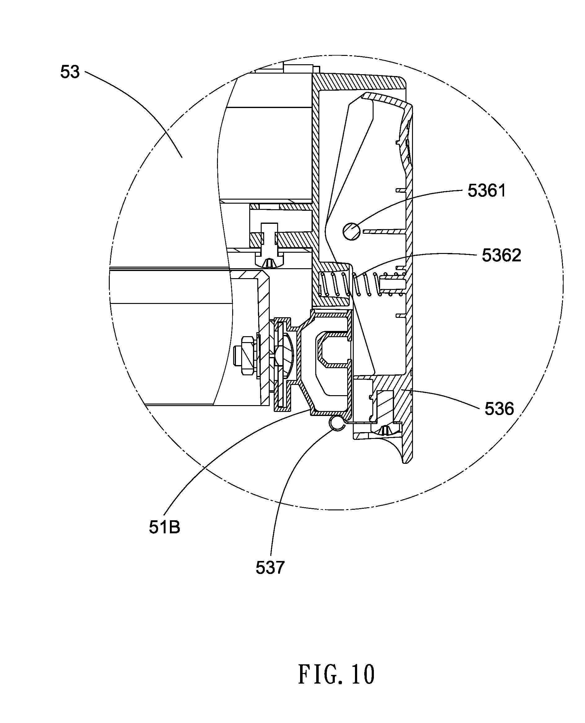
[0017] FIG. 10 is a detailed view of the area in circle D of FIG. 9;
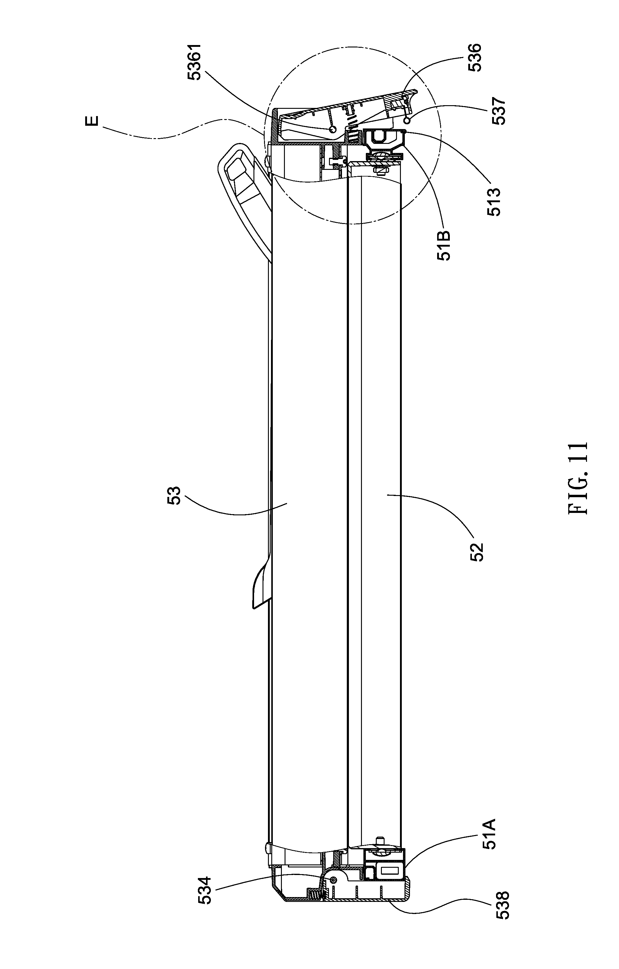
[0018] FIG. 11 is a view similar to FIG. 9 where the lever is unlocked;
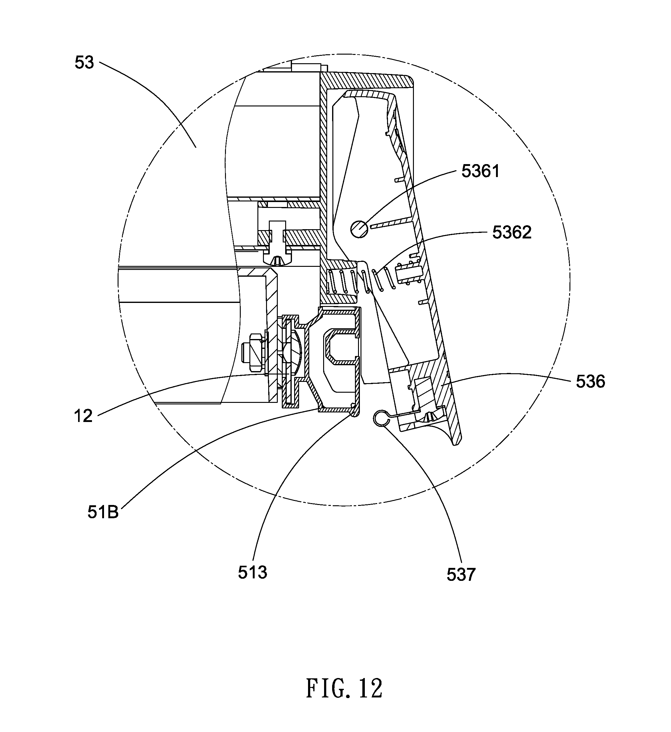
[0019] FIG. 12 is a detailed view of the area in circle E of FIG. 11;
[0020] FIG. 13 is another longitudinal sectional view of the fence assembly where the bar is pivoted about a rear end thereof;
[0021] FIG. 14 is a detailed view of the area in circle F of FIG. 13;
[0022] FIG. 15 is a perspective view of the main portion of the fence assembly; and
[0023] FIG. 16 is a view similar to FIG. 15 showing the side plat being open.
DETAILED DESCRIPTION OF THE INVENTION
[0024] Referring to FIGS. 3 to 16, a table saw 1 in accordance with the invention comprises the following components as discussed in detail below.
[0025] A table assembly 10 includes a rectangular table 11 and two rails 12 on front and rear ends of the table 11 respectively. A base assembly 20 supports the table assembly 10. A saw assembly 30 is disposed on the table assembly 10. A height adjustment assembly 40 is disposed on a front panel of the base assembly 20. A fence assembly 50 as the subject of the invention is discussed in detail below.
[0026] The fence assembly 50 includes lengthwise rear and front sliding members 51A, 51B slidably disposed on the rails 12 respectively, the rear sliding member 51A having three equally spaced top projections 511, the front sliding member 51B having three equally spaced forward projections 512, a transverse member 52 interconnecting the distal ends of the sliding members 51A, 51B, and a workpiece guide bar 53 disposed on the transverse member 52 and having two ends disposed on the sliding members 51A, 51B respectively.
[0027] The workpiece guide bar 53 includes a rectangular, pivotal side plat 531 on an outer surface, the side plate 531 having two protrusions 5311 on two ends respectively, the protrusions 5311 configured to releasably secure to two cavities 5312 on the outer surface of the workpiece guide bar 53 respectively so that the side plate 531 may be open or close.
[0028] An inner surface of either end of the workpiece guide bar 53 further comprises a rear positioning element 532 having a horizontally forward recess 5321 for complimentary receipt of the top projection 511, and a front positioning element 533 having a vertically downward recess 5331 for complimentary receipt of the forward projection 512. The front positioning element 533 is secured to an inner surface of the workpiece guide bar 532. The rear and front positioning elements 532, 533 are configured to position on the rear and front sliding members 51A, 51B respectively. Further, a rear end of the workpiece guide bar 53 is pivotably secured to a rear locking element 538 by means of a pivot 534 and a compression spring 535. Thus, the rear end of the workpiece guide bar 53 and the rear locking element 538 may be resiliently connected together. A bottom of the rear locking element 538 is provided with a tab 5381 for supporting the rear sliding member 51A. Side of the rear locking element 538 is secured to the rear positioning element 532. Thus, the rear end of the workpiece guide bar 53 and the rear positioning element 532 are resiliently connected together.
[0029] Furthermore, the receipt of the projection 511 in the recess 5321 slidably positions the workpiece guide bar 53 on the rear sliding members 51A, the receipt of the projection 512 in the recess 5331 slidably positions the workpiece guide bar 53 on the front sliding member 51B.
[0030] The workpiece guide bar 53 further comprises a lever 536 pivotably secured to a front end thereof by means of a pivot 5361 and a compression spring 5362, and a latch 537 on a lower, inner portion.
[0031] The latch 537 is disengaged from a protuberance 513 on a bottom of the front sliding member 51B (see FIG. 12). The workpiece guide bar 53 is unlocked. Thus, the rear and front positioning elements 532, 533 are capable of quick positioning on the projection 511 and the projection 512 on the rear and front sliding members 51A, 51B respectively. As a result, the workpiece guide bar 53 is unlocked and can be lifted obliquely (see FIG. 13). A user may press the lever 536 to lock the workpiece guide bar 53 (see FIG. 10). As a result, a distance between the workpiece guide bar 53 and the saw assembly 30 can be adjusted.
[0032] It is clear that the latch 537 is engaged with the protuberance 513 on the bottom of the front sliding member 51B by clockwise pivoting the lever 536 (see FIG. 10). The lever 536 is locked. Thus, the workpiece guide bar 53 is locked and can not be lifted. As a result, the distance between the workpiece guide bar 53 and the saw assembly 30 is fixed.
[0033] While the invention has been described in terms of preferred embodiments, those skilled in the art will recognize that the invention can be practiced with modifications within the spirit and scope of the appended claims.
* * * * *
D00000
D00001
D00002
D00003
D00004
D00005
D00006
D00007
D00008
D00009
D00010
D00011
D00012
D00013

D00014

D00015

D00016

XML
uspto.report is an independent third-party trademark research tool that is not affiliated, endorsed, or sponsored by the United States Patent and Trademark Office (USPTO) or any other governmental organization. The information provided by uspto.report is based on publicly available data at the time of writing and is intended for informational purposes only.
While we strive to provide accurate and up-to-date information, we do not guarantee the accuracy, completeness, reliability, or suitability of the information displayed on this site. The use of this site is at your own risk. Any reliance you place on such information is therefore strictly at your own risk.
All official trademark data, including owner information, should be verified by visiting the official USPTO website at www.uspto.gov. This site is not intended to replace professional legal advice and should not be used as a substitute for consulting with a legal professional who is knowledgeable about trademark law.