Staple Cartridge
Huitema; Thomas W. ; et al.
U.S. patent application number 16/153111 was filed with the patent office on 2019-04-11 for staple cartridge. The applicant listed for this patent is Ethicon LLC. Invention is credited to Thomas W. Huitema, Douglas J. Siebenaler.
| Application Number | 20190105042 16/153111 |
| Document ID | / |
| Family ID | 44774145 |
| Filed Date | 2019-04-11 |


View All Diagrams
| United States Patent Application | 20190105042 |
| Kind Code | A1 |
| Huitema; Thomas W. ; et al. | April 11, 2019 |
STAPLE CARTRIDGE
Abstract
A staple cartridge can comprise a plurality of staples positioned within a cartridge body, wherein the cartridge body can comprise a tissue-contacting deck and a plurality of ridges extending from the tissue-contacting deck. The ridges can be configured to prevent, or reduce the possibility of, tissue from moving relative to the staple cartridge during use. The staple cartridge can further comprise a plurality of staple cavities, wherein each staple cavity can comprise an opening in the deck which is at least partially surrounded by a ridge. The ridges can comprise a uniform height or a height which varies along the length thereof. The height can vary relative to a proximal end and a distal end of the cartridge body and/or between the center of the cartridge body and the side.
| Inventors: | Huitema; Thomas W.; (West Chester, OH) ; Siebenaler; Douglas J.; (Maineville, OH) | ||||||||||
| Applicant: |
|
||||||||||
|---|---|---|---|---|---|---|---|---|---|---|---|
| Family ID: | 44774145 | ||||||||||
| Appl. No.: | 16/153111 | ||||||||||
| Filed: | October 5, 2018 |
Related U.S. Patent Documents
| Application Number | Filing Date | Patent Number | ||
|---|---|---|---|---|
| 14733026 | Jun 8, 2015 | 10130363 | ||
| 16153111 | ||||
| 13772903 | Feb 21, 2013 | 9131940 | ||
| 14733026 | ||||
| 12893461 | Sep 29, 2010 | 8733613 | ||
| 13772903 | ||||
| Current U.S. Class: | 1/1 |
| Current CPC Class: | A61B 17/07207 20130101; A61B 17/0682 20130101; A61B 2017/07278 20130101; A61B 2017/07214 20130101; A61B 2017/07271 20130101 |
| International Class: | A61B 17/072 20060101 A61B017/072; A61B 17/068 20060101 A61B017/068 |
Claims
1. A staple cartridge, comprising: a plurality of staples; and a cartridge body, comprising: a tissue-contacting deck; a plurality of staple cavities, wherein each said staple cavity comprises an opening in said deck, and wherein a said staple is positioned in each said staple cavity; and a plurality of ridges extending from said tissue-contacting deck, wherein each said opening is at least partially surrounded by a said ridge.
2. The staple cartridge of claim 1, wherein each said opening is entirely encompassed by a said ridge.
3. The staple cartridge of claim 1, further comprising a plurality of staple drivers configured to eject said staples from said staple cavities, wherein each said staple is supported by a staple driver, wherein each said staple comprises at least one tip, and wherein said tips of said staples are positioned above said tissue-contacting deck.
4. The staple cartridge of claim 3, wherein each said ridge comprises a top surface, and wherein said tips are positioned below said top surfaces.
5. The staple cartridge of claim 1, wherein each said opening comprises a proximal end and a distal end, and wherein said ridges surround said proximal ends and said distal ends.
6. The staple cartridge of claim 5, wherein said plurality of staple cavities comprise a first row of staple cavities housing a first row of staples and a second row of staple cavities housing a second row of staples, and wherein the ridges surrounding the openings of said first row of stale cavities are connected to the ridges surrounding the openings of said second row of staple cavities.
7. The staple cartridge of claim 1, wherein each said ridge comprises an array of knurls.
8. The staple cartridge of claim 7, wherein said knurls each comprise one of a pyramid-shaped configuration and a cone-shaped configuration.
9. The staple cartridge of claim 7, wherein said knurls cover the entirety of said tissue-contacting deck.
10. The staple cartridge of claim 1, wherein said plurality of staple cavities comprises a row of staple cavities housing a row of staples, and wherein said ridges are positioned intermediate the staple cavities in said row of staple cavities.
11. The staple cartridge of claim 10, wherein each said ridge comprises an X-shaped configuration.
12. A staple cartridge, comprising: a plurality of staples; and a cartridge body, comprising: a middle portion; a lateral portion; a tissue-contacting deck; a plurality of staple cavities, wherein a said staple is positioned in each said staple cavity; and a plurality of ridges extending from said tissue-contacting deck, wherein each said ridge extends between said middle portion and said lateral portion.
13. The staple cartridge of claim 12, wherein each said ridge comprises a uniform height.
14. The staple cartridge of claim 12, wherein each said ridge comprises a height which varies along the length thereof.
15. The staple cartridge of claim 14, wherein each said ridge comprises a height which tapers from a tall portion positioned adjacent to said lateral portion of said cartridge body to a short portion positioned adjacent to said middle portion of said cartridge body.
16. The staple cartridge of claim 12, wherein said plurality of staple cavities comprises a first row of staple cavities housing a first row of staples and a second row of staple cavities housing a second row of staples, and wherein each said ridge extends along a line which transects said first row of staples and said second row of staples.
17. A staple cartridge, comprising: a plurality of staples; and a cartridge body, comprising: a proximal end; a distal end; a tissue-contacting deck; a plurality of staple cavities, wherein a said staple is positioned in each said staple cavity; and a plurality of ridges extending from said tissue-contacting deck, wherein each said ridge comprises a height which varies between a proximal height and a distal height, and wherein said proximal height is closer to said proximal end than said distal height.
18. The staple cartridge of claim 17, wherein said proximal height is taller than said distal height.
19. The staple cartridge of claim 18, wherein said height of each said ridge tapers between said proximal height and said distal height.
20. The staple cartridge of claim 17, wherein each said ridge comprises a ramp having a maximum height at said proximal end.
Description
CROSS-REFERENCE TO RELATED APPLICATIONS
[0001] This application is a continuation application claiming priority under 35 U.S.C. .sctn. 120 to U.S. patent application Ser. No. 14/733,026, entitled STAPLE CARTRIDGE, filed Jun. 8, 2015, now U.S. Patent Application Publication No. 2015/0265276, which is a continuation application claiming priority under 35 U.S.C. .sctn. 120 to U.S. patent application Ser. No. 13/772,903, entitled STAPLE CARTRIDGE, filed Feb. 21, 2013, which issued on Sep. 15, 2015 as U.S. Pat. No. 9,131,940, which is a continuation application claiming priority under 35 U.S.C. .sctn. 120 to U.S. patent application Ser. No. 12/893,461, entitled STAPLE CARTRIDGE, filed Sep. 29, 2010, which issued on May 27, 2014 as U.S. Pat. No. 8,733,613, the entire disclosures of which are hereby incorporated by reference herein.
BACKGROUND
i. Technical Field
[0002] The present invention relates to stapling instruments and, in various embodiments, to a surgical stapling instrument for producing one or more rows of staples.
ii. Background of the Related Art
[0003] A stapling instrument can include a pair of cooperating elongate jaw members, wherein each jaw member can be adapted to be inserted into a patient and positioned relative to tissue that is to be stapled and/or incised. In various embodiments, one of the jaw members can support a staple cartridge with at least two laterally spaced rows of staples contained therein, and the other jaw member can support an anvil with staple-forming pockets aligned with the rows of staples in the staple cartridge. Generally, the stapling instrument can further include a pusher bar and a knife blade which are slidable relative to the jaw members to sequentially eject the staples from the staple cartridge via camming surfaces on the pusher bar and/or camming surfaces on a wedge sled that is pushed by the pusher bar. In at least one embodiment, the camming surfaces can be configured to activate a plurality of staple drivers carried by the cartridge and associated with the staples in order to push the staples against the anvil and form laterally spaced rows of deformed staples in the tissue gripped between the jaw members. In at least one embodiment, the knife blade can trail the camming surfaces and cut the tissue along a line between the staple rows. Examples of such stapling instruments are disclosed in U.S. Pat. No. 7,794,475, entitled SURGICAL STAPLES HAVING COMPRESSIBLE OR CRUSHABLE MEMBERS FOR SECURING TISSUE THEREIN AND STAPLING INSTRUMENTS FOR DEPLOYING THE SAME, the entire disclosure of which is hereby incorporated by reference herein.
[0004] The foregoing discussion is intended only to illustrate various aspects of the related art in the field of the invention at the time, and should not be taken as a disavowal of claim scope.
SUMMARY
[0005] In at least one form, a staple cartridge can comprise a plurality of staples and a cartridge body. The cartridge body can comprise a tissue-contacting deck, a plurality of staple cavities, wherein each staple cavity comprises an opening in the deck, and wherein a staple is positioned in each staple cavity. The cartridge body can further comprise a plurality of ridges extending from the tissue-contacting deck, wherein each opening is at least partially surrounded by a ridge.
[0006] In at least one form, a staple cartridge can comprise a plurality of staples and a cartridge body. The cartridge body can comprise a middle portion, a side portion, a tissue-contacting deck, a plurality of staple cavities, wherein a staple is positioned in each staple cavity, and a plurality of ridges extending from the tissue-contacting deck, wherein each ridge extends between the middle portion and the side portion of the cartridge body.
[0007] In at least one form, a staple cartridge can comprise a plurality of staples and a cartridge body. The cartridge body can comprise a proximal end, a distal end, a tissue-contacting deck, a plurality of staple cavities, wherein a staple is positioned in each staple cavity, and a plurality of ridges extending from the tissue-contacting deck, wherein each ridge comprises a height which varies between a proximal height and a distal height, and wherein the proximal height is closer to the proximal end than the distal height.
[0008] The foregoing discussion should not be taken as a disavowal of claim scope.
BRIEF DESCRIPTION OF THE DRAWINGS
[0009] Various features of the embodiments described herein are set forth with particularity in the appended claims. The various embodiments, however, both as to organization and methods of operation, together with advantages thereof, may be understood in accordance with the following description taken in conjunction with the accompanying drawings as follows.
[0010] FIG. 1 is an elevational view of a surgical stapling instrument.
[0011] FIG. 2 is a cross-sectional view of an end effector of the surgical stapling instrument of FIG. 1 taken along line 2-2 in FIG. 1.
[0012] FIG. 3 is a cross-sectional perspective view of the end effector of FIG. 1.
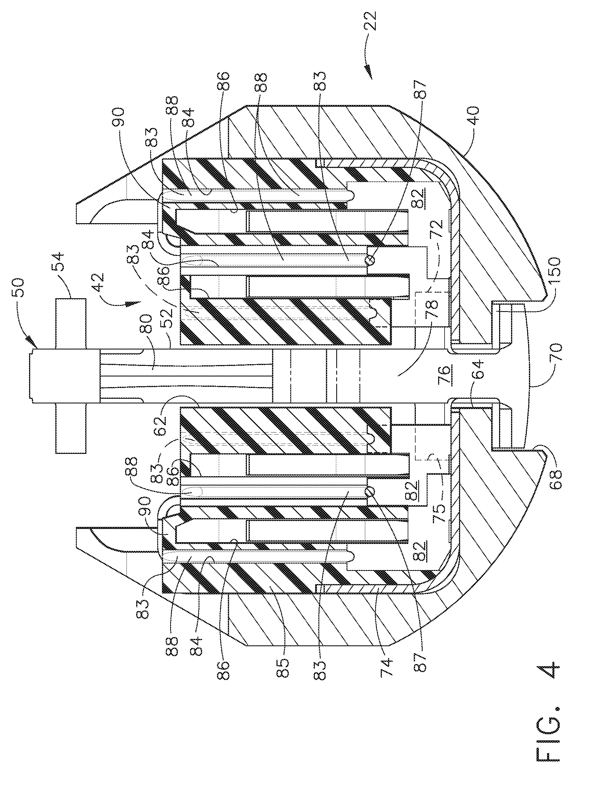
[0013] FIG. 4 is a cross-sectional view of the end effector of FIG. 1 illustrating staples contained therein in an unfired configuration.
[0014] FIG. 5 is a diagram illustrating the staples of FIG. 4 in a fired configuration.
[0015] FIG. 6 is a diagram illustrating the end effector of FIG. 1 being used to staple and transect tissue.
[0016] FIG. 7 is a perspective view of a staple cartridge in accordance with at least one embodiment comprising a plurality of ridges extending from a cartridge body.
[0017] FIG. 8 is a detail view of the staple cartridge of FIG. 7.
[0018] FIG. 8A is a cross-sectional view of the staple cartridge of FIG. 7.
[0019] FIG. 9 is a detail view illustrating staples positioned within staple cavities defined in the staple cartridge of FIG. 7.
[0020] FIG. 10 is a partial perspective view of a staple cartridge in accordance with at least one alternative embodiment comprising a plurality of transverse ridges extending from a cartridge body.
[0021] FIG. 11 is a partial perspective view of a staple cartridge in accordance with at least one alternative embodiment comprising a plurality of transverse ridges extending from a cartridge body.
[0022] FIG. 12 is a partial perspective view of a staple cartridge in accordance with at least one alternative embodiment comprising a plurality of ridges surrounding the proximal and distal ends of staple cavity openings defined in a cartridge body.
[0023] FIG. 13 is a partial perspective view of a staple cartridge in accordance with at least one alternative embodiment comprising a plurality of ridges surrounding the proximal and distal ends of staple cavity openings defined in a cartridge body.
[0024] FIG. 14 is a partial perspective view of a staple cartridge in accordance with at least one alternative embodiment comprising a plurality of knurled ridges extending from a cartridge body.
[0025] FIG. 15 is a partial perspective view of a staple cartridge in accordance with at least one alternative embodiment comprising a plurality of knurled ridges extending from a cartridge body.
[0026] FIG. 15A is a perspective view of a pyramidal knurl in accordance with at least one embodiment.
[0027] FIG. 15B is a perspective view of a frustoconical knurl in accordance with at least one embodiment.
[0028] FIG. 15C is a perspective view of a triangular knurl in accordance with at least one embodiment.
[0029] FIG. 16 is a partial perspective view of a staple cartridge in accordance with at least one alternative embodiment comprising a plurality of ridges entirely surrounding staple cavity openings defined in a cartridge body.
[0030] FIG. 16A is a partial perspective view of a staple cartridge in accordance with at least one alternative embodiment comprising a plurality of ridges entirely surrounding staple cavity openings defined in a cartridge body.
[0031] FIG. 17 is a perspective view of a staple cartridge in accordance with at least one alternative embodiment comprising a plurality of longitudinal ridges extending from a cartridge body.
[0032] FIG. 18 is a detail view of the staple cartridge of FIG. 17.
[0033] Corresponding reference characters indicate corresponding parts throughout the several views. The exemplifications set out herein illustrate various embodiments of the invention, in one form, and such exemplifications are not to be construed as limiting the scope of the invention in any manner.
DETAILED DESCRIPTION
[0034] Numerous specific details are set forth to provide a thorough understanding of the overall structure, function, manufacture, and use of the embodiments as described in the specification and illustrated in the accompanying drawings. It will be understood by those skilled in the art, however, that the embodiments may be practiced without such specific details. In other instances, well-known operations, components, and elements have not been described in detail so as not to obscure the embodiments described in the specification. Those of ordinary skill in the art will understand that the embodiments described and illustrated herein are non-limiting examples, and thus it can be appreciated that the specific structural and functional details disclosed herein may be representative and illustrative. Variations and changes thereto may be made without departing from the scope of the claims.
[0035] Reference throughout the specification to "various embodiments," "some embodiments," "one embodiment," or "an embodiment", or the like, means that a particular feature, structure, or characteristic described in connection with the embodiment is included in at least one embodiment. Thus, appearances of the phrases "in various embodiments," "in some embodiments," "in one embodiment," or "in an embodiment", or the like, in places throughout the specification are not necessarily all referring to the same embodiment. Furthermore, the particular features, structures, or characteristics may be combined in any suitable manner in one or more embodiments. Thus, the particular features, structures, or characteristics illustrated or described in connection with one embodiment may be combined, in whole or in part, with the features structures, or characteristics of one or more other embodiments without limitation. Furthermore, it will be appreciated that for conciseness and clarity, spatial terms such as "vertical," "horizontal," "up," and "down", for example, may be used herein with respect to the illustrated embodiments. However, these terms are used to assist the reader and are not intended to be limiting and absolute.
[0036] Turning to FIG. 1, a surgical stapling and severing instrument 10 can include a handle portion 12 that can be manipulated in order to position an implement portion 14 in a surgical site. In various embodiments, the implement portion 14 can include an end effector 16 attached to an elongate shaft 18. In various circumstances, the implement portion 14 can be sized and configured to be inserted through a cannula of a trocar (not shown) into the surgical site in order to perform an endoscopic or laparoscopic surgical procedure, for example. The end effector 16 can comprise an upper jaw, or anvil, 20 and a lower jaw 22, wherein the anvil 20 can be moved between an open position and a closed position when the closure trigger 24 of the handle portion 12 is moved, or depressed, toward a pistol grip 26 of the handle portion 12. In various embodiments, the depression of the closure trigger 24 can advance an outer closing sleeve 28 of the elongate shaft 18 wherein the outer closing sleeve 28 can contact the anvil 20 and pivot the anvil 20 into its closed position. In certain circumstances, the surgeon may rotate the implement potion 14 about its longitudinal axis by twisting a shaft rotation knob 30. In any event, once the end effector 16 has been inserted into an insufflated body cavity, for example, the closure trigger 24 may be released thereby allowing the anvil 20 to be biased open by a spring (not shown) and positioned relative to the targeted tissue. In various embodiments, the closure trigger 24 can be locked in its depressed condition and, in at least one embodiment, the handle portion 12 can further comprise a lock release actuator 44 which can be depressed to unlock the closure trigger 24. Once the anvil 20 and the lower jaw 22 have been suitably positioned relative to the tissue in the surgical site, the closure trigger 24 can be depressed once again in order to close the anvil 20 and compress the tissue against a staple cartridge 42 attached to the bottom jaw 22.
[0037] Once the anvil 20 has been closed, a firing trigger 32 can be drawn, or depressed, toward the closure trigger 24 and the pistol grip 26 in order to apply a firing force or motion to a firing member and advance the firing member from an unfired position. In various embodiments, the firing member can comprise a proximal firing rod 34 which is attached to a distal firing bar 36. In at least one such embodiment, the firing rod 34 and/or the firing bar 36 can be supported within a frame 38 in shaft 18 which can extend between the handle portion 12 and the end effector 16. As a result of the firing motion applied to the firing member, the firing bar 36 can be advanced distally within a elongate staple cartridge channel 40 of the lower jaw 22 and a staple cartridge 42 positioned within the cartridge channel 40. In various embodiments, referring to FIG. 2, the firing bar 36 can comprise an attachment portion 48 that is attached to an E-beam 50 which can translate within the end effector 16. The E-beam 50 can comprise a vertical portion 52 which can pass through a narrow longitudinal anvil slot 58 extending through a tissue-contacting surface 60 in the anvil 20, a narrow vertical slot 62 in the staple cartridge 42, and a narrow longitudinal channel slot 64 in the elongate staple channel 40 when the E-beam 50 is advanced distally. Referring now to FIGS. 2 and 3, the anvil slot 58 can extend upwardly into the anvil 20 and can comprise an end which opens into a laterally-widened longitudinal channel 66 sized and configured to receive an upper pin 54 that extends laterally from the vertical portion 52. Similarly, the channel slot 64 can extend downwardly into the channel 40 and can comprise an end which opens into a laterally-widened longitudinal channel 68 sized and configured to receive one or more lower feet 70 extending laterally from the vertical portion 52.
[0038] In various embodiments, further to the above, the E-beam 50 can further comprise one or more middle pins 72 which can extend laterally from the vertical portion 52 and can be configured to slide along a top surface of a bottom tray 74 of the staple cartridge 42. In certain embodiments, the middle pins 72 can be configured to seat the staple cartridge 42, or assure that the staple cartridge 42 remains seated, in the channel 40. A longitudinal firing recess 75 formed in the staple cartridge 42 above the bottom tray 74 is sized to allow the middle pins 72 to translate through the staple cartridge 42. In various embodiments, the E-beam 50 can further comprise a distal drive surface 76 which can be configured to translate through the vertical slot 62 in the staple cartridge 42 and drive a wedge sled 78 distally through the staple cartridge 42. In certain embodiments, the wedge sled 78 can be integrally-formed within the E-beam 50 while, in other embodiments, the wedge sled 78 can reside in the staple cartridge 42 and can be contacted by the drive surface 76 as the E-beam 50 is advanced distally. The vertical portion 52 of the E-beam 50 can further comprise a cutting surface 80 which extends along a distal edge above the distal drive surface 76 and below the upper pin 54 that severs the clamped tissue 46 as the tissue 46 is being stapled. Referring now to FIG. 4, the wedge sled 78 can be configured to engage one or more staple drivers 82 and drive the staple drivers 82 upwardly toward the anvil 20. In various embodiments, staples, such as staples 83, for example, can be seated on and/or otherwise supported by the staple drivers 82 such that, as the staple drivers 82 are lifted upwardly, the staples 83 can be lifted upwardly as well. In at least one such embodiment, the staples 83 can also be at least partially positioned within staple cavities, or pockets, 84 in a staple cartridge body 85 of the staple cartridge 42 wherein, as the staples 83 are lifted upwardly, the staples 83 can contact the anvil 20 and can be ejected from the staple cavities 84. In at least one embodiment, referring again to FIG. 4, the bottom tray 74 can be attached to the cartridge body 85 in order to retain the staple drivers 82 and the staples 83 within the staple cartridge 42 until the staples 83 are deployed therefrom as described above.
[0039] In use, referring now to FIGS. 5 and 6, the anvil 20 can be positioned on one side of the tissue 46 and the bottom jaw 22 can be positioned on the opposite side of the tissue 46 such that, when the anvil 20 is closed onto the tissue, the tissue-contacting surface 60 of the anvil 20 and the tissue-contacting deck 90 of the staple cartridge 42 can compress the tissue 46 between an uncompressed thickness 91 and a compressed thickness 92. In order to staple and transect the tissue 46, as described above, the wedge sled 78 can be advanced distally within the staple cartridge 42 in order to lift the staple drivers 82 toward the anvil 20 and deform the staples 83. In various embodiments, each staple driver 82 can comprise one or more slots defined therein which can be configured to receive and releasably hold the bases 87 of the staples 83 in position. In at least one such embodiment, each staple 83 can comprise one or more staple legs 88 extending from the base 87, wherein the staple legs 88 can extend upwardly into the staple cavities 84. In various embodiments, the tips of the staple legs 88 can be recessed with respect to the deck, or tissue-contacting surface, 90 of the cartridge body 85 when the staples 83 are in their unfired position. As the staples 83 are being lifted upwardly by the drivers 82, the tips of the staple legs 88 can emerge from the staple cavities 84, penetrate the tissue 46, and contact the anvil forming pockets 89 positioned opposite the staple cavities 84. The anvil forming pockets 89 can be configured to deform the staples 83 into any suitable shape, such as the B-form shape depicted in FIG. 5, for example. As the staples 83 are deployed, referring now to FIG. 6, the cutting edge 80 can transect the tissue 46 into stapled portions 94.
[0040] As described above, the jaw members of an end effector can be configured to apply a compressive pressure, or force, to the tissue being stapled. In various circumstances, however, the tissue can be slippery, for example, and at least a portion of the tissue can slide relative to the jaw members. In certain circumstances, the tissue can slide out of the distal end of the end effector in a longitudinal direction and/or slide out of the sides of the end effector in a direction which is transverse to the longitudinal direction. In some circumstances, portions of the tissue can milk out of the distal end of the end effector and/or the sides of the end effector when the tissue is compressed. In various embodiments disclosed herein, a staple cartridge can comprise one or more tissue retention features which can be configured to prevent, or at least reduce the possibility of, tissue positioned within the end effector from moving relative to the end effector.
[0041] In various embodiments, referring now to FIGS. 7 and 8, a staple cartridge, such as staple cartridge 142, for example, can comprise a cartridge body 185 and a plurality of staples, such as staples 187 (FIG. 9), for example, positioned within the cartridge body 185. The cartridge body 185 can comprise a proximal end 141 and a distal end 143, wherein the proximal end 141 can be configured to be inserted into a proximal end of a staple cartridge channel and the distal end 143 can be configured to be inserted into a distal end of the staple cartridge channel. In at least one embodiment, the cartridge body 185 can comprise a plurality of staple cavities 184 which can each be configured to receive a staple 187 therein. In certain alternative embodiments, although not illustrated, a staple cavity can comprise more than one staple positioned therein. In any event, the staple cavities 184 can be arranged in a plurality of rows within the cartridge body 185. More particularly, in at least one embodiment, the staple cavities 184 can be arranged in three staple rows, for example, on a first side 145 of the cartridge body 185 and three staple rows, for example, on a second side 147 of the cartridge body 185. In at least one such embodiment, the first side 145 and the second side 147 of the cartridge body 185 can be separated by a knife slot 162 which can be configured to slidably receive a cutting member therein. In various other embodiments, a cartridge can comprise any other suitable number of staple rows, such as two staple rows or four staple rows, for example, on each side of the knife slot 162. Referring to FIG. 9, in various embodiments, the staple cartridge 142 can further comprise a plurality of staple drivers 182 configured to support the staples 187 and/or eject the staples 187 from the staple cavities 184. In certain embodiments, each staple cavity 184 can comprise an open end, or opening, 110 in the deck 190 of the cartridge body 185 through which the staples 187 can be ejected.
[0042] In various embodiments, referring primarily to FIG. 8, the staple cavities 184 can be arranged such that they are staggered longitudinally relative to one another. For example, the staple cavities 184 on the first side 145 of the cartridge body 185, for example, can be arranged in an innermost row of staple cavities 184, an intermediate row of staple cavities 184, and an outermost row of staple cavities 184, wherein the staple cavities 184 in one row may not be aligned transversely with the staple cavities 184 in one or both of the other rows. In at least one embodiment, each staple cavity 184 can comprise a proximal end 111 and a distal end 112, wherein the proximal end 111 of each staple cavity 184 can be positioned closer to the proximal end 141 of the cartridge body 185 than the distal end 112. Likewise, the distal end 112 of each cavity 184 can be positioned closer to the distal end 143 of the cartridge body 185 than the proximal end 111. In various embodiments, the innermost row of staple cavities 184 can be positioned such that the distal ends 112 of the staple cavities 184 within the innermost row are positioned distally with respect to the distal ends 112 of the staple cavities 184 in the intermediate row of staple cavities 184. Similarly, the outermost row of staple cavities 184 can be positioned such that the distal ends 112 of the staple cavities 184 within the outermost row are positioned distally with respect to the distal ends 112 of the staple cavities in the intermediate row of staple cavities 184. For example, the distalmost staple cavity 184 in the innermost row can be positioned distally with respect to the distalmost staple cavity 184 in the intermediate row and, similarly, the distalmost staple cavity 184 in the outermost row can be positioned distally with respect to the distalmost staple cavity 184 in the intermediate row. In certain embodiments, the staple cavities 184 of the innermost row and the staple cavities 184 of the outermost row can be aligned transversely with each other such that, one, the distal ends 112 of the innermost staple cavities 184 are aligned with the distal ends 112 of the outermost staple cavities 184 and, two, the proximal ends 111 of the innermost staple cavities 184 are aligned with the proximal ends 111 of the outermost staple cavities 184. In various embodiments, each staple cavity 184, and their openings 110, can have the same, or at least approximately the same, configuration and, in at least one embodiment, the staple cavities 184 can be spaced equidistantly, or at least substantially equidistantly, relative to one another within a staple row.
[0043] In various embodiments, referring again to FIGS. 7 and 8, the cartridge body 185 of the staple cartridge 142 can further comprise one or more ridges, such as ridges 113, 114, and 115, for example, which can be configured to contact and compress the targeted tissue. More particularly, referring now to FIG. 8A, the anvil 120 of an end effector can be closed in order to compress the tissue T against the staple cartridge 142 wherein, in such circumstances, the tissue-contacting deck 190 and the ridges 113, 114, and 115 extending therefrom can engage the tissue. As the anvil 120 is closed, in certain circumstances, the anvil 120 can push the tissue toward the staple cartridge 142 such that the tissue first contacts the ridges 113, 114, and 115 and then contacts the cartridge deck 190. In other circumstances, the staple cartridge 142 can be positioned against the tissue such that the ridges 113, 114, and 115 contact the tissue before the tissue is contacted by the cartridge deck 190. In any event, the ridges 113, 114, and 115, once in contact in with the tissue, can prevent, or at least limit, relative movement between the tissue and the staple cartridge 142. In certain embodiments, the ridges 113, 114, and 115 can extend upwardly from a flat, or at least substantially flat, cartridge deck 190 and can define one or more pockets or channels, for example, which can be configured to receive a portion of the tissue therein and, as a result, inhibit the relative movement of the tissue in the longitudinal direction and/or the transverse direction of the end effector, especially when the tissue is at least partially compressed between the anvil 120 and the ridges 113, 114, and 115. In various embodiments, as the ridges 113, 114, and 115 extend above the cartridge deck 190, the tissue positioned intermediate the anvil 120 and the ridges 113, 114, and 115 can be compressed before the tissue positioned intermediate the anvil 120 and the cartridge deck 190 is compressed. In some such circumstances, as a result, the tissue positioned between the anvil 120 and the ridges 113, 114, and 115 can be pre-compressed, i.e., at least partially compressed before the other portions of the tissue positioned between the anvil 120 and the cartridge deck 190 are compressed. Owing to this pre-compression, in various circumstances, portions of the tissue can be controlled or prevented from slipping out of the end effector before the tissue is fully compressed as described in greater detail below.
[0044] In various embodiments, referring again to FIGS. 7 and 8, the ridges 113 extending from the cartridge deck 190 can extend around the proximal ends 111 of the staple cavity openings 110. Similarly, the ridges 114 extending from the cartridge deck 190 can extend around the distal ends 112 of the staple cavity openings 110. These proximal ridges 113 and distal ridges 114, in various embodiments, can be configured to engage the tissue positioned above and/or around the staple cavities 184 and hold these portions of the tissue in position as the tissue is being compressed and/or stapled. Stated another way, holding the tissue positioned above and/or surrounding the staple cavities 184 can provide localized control over the portions of the tissue that are going to be stapled and, as a result, prevent, or at least limit, the relative movement between these portions of the tissue and the staple cartridge 142. In various embodiments, the ridges 113 and 114 can be positioned around the openings 110 of all of the staple cavities 184 or only some of the staple cavities 184. In at least one embodiment, a cartridge body may comprise ridges 113 and 114 surrounding only the staple cavities 184 in the outermost rows of the first and second sides 145 and 147. In such embodiments, the ridges surrounding the outermost rows of staple cavities 184 may be sufficient to block the lateral movement of the tissue within the end effector. In certain embodiments, a cartridge body may only comprise proximal ridges 113 surrounding the proximal ends 111 of the proximalmost staple cavities 184 and/or distal ridges 114 surrounding the distal ends 112 of the distalmost staple cavities 184. In such embodiments, the ridges surrounding the proximalmost and distalmost staple cavities 184 may be sufficient to block the longitudinal movement of the tissue within the end effector.
[0045] In various embodiments, further to the above, each proximal ridge 113 can comprise an arcuate or curved profile, for example, which surrounds a proximal end 111 of an opening 110. The arcuate profile of each proximal ridge 113 can be defined by one radius of curvature or more than one radius of curvature. Similarly, each distal ridge 114 can comprise an arcuate or curved profile, for example, which surrounds a distal end 112 of an opening 110. The arcuate profile of each distal ridge 114 can be defined by one radius of curvature or more than one radius of curvature. In certain embodiments, further to the above, each ridge 113 and 114 can form a pocket which can receive a portion of tissue that is being compressed and prevent that portion of tissue from moving longitudinally and/or transversely relative to the staple cartridge 142. In various embodiments, the staple cartridge 142 can further comprise intermediate ridges 115 which can extend between and/or connect adjacent ridges 113 and 114 in adjacent rows of staple cavities 184. In at least one such embodiment, one or more ridges 113, 114, and 115 can co-operatively form an undulating ridge extending across the first side 145 or the second side 147 of the cartridge body 185 wherein, in at least one embodiment, the undulating ridge can extend between a center portion and a side portion of the cartridge body 142. In various embodiments, each undulating ridge can comprise a plurality of wave portions winding around the proximal and distal ends of the staple cavities 184, for example. In various embodiments, each ridge 113, 114, and 115 can comprise a height defined from the cartridge deck 190 wherein, in certain embodiments, the height of each ridge 113, 114, and 115 can be uniform, or at least substantially uniform, across the length thereof. In at least one embodiment, each ridge 113, 114, and 115 can have the same, or at least substantially the same, height.
[0046] In various embodiments, as described above, the staple cavities defined in a staple cartridge body can comprise a staple positioned therein wherein the entirety of the staple can be positioned below the top surface, or tissue-contacting surface, of the cartridge deck when the staple is in its unfired position. In certain other embodiments, at least a portion of the staple, such as the tips of the staple legs, for example, can extend above the top surface, or tissue-contacting surface, of the cartridge deck when the staples are in their unfired position. In some such embodiments, the tips of the staples can protrude from the deck and may snag on tissue as the staple cartridge is inserted into a surgical site. In at least one embodiment, referring now to FIG. 9, the ridges 113 and 114, for example, which extend above the tissue-contacting cartridge deck 190, can at least partially surround and protect the staple legs 183 of staples 187 when they extend above the cartridge deck 190 in their unfired position. Although the ridges 113 and 114 may not extend entirely around each opening 110, in various embodiments, the proximal ridge 113 may sufficiently surround one of the staple leg tips and the distal ridge 114 may sufficiently surround the other staple leg tip such that the staple leg tips do not contact the tissue prior to the tissue being compressed against the staple cartridge 142 and/or the staples 187 being ejected from the staple cartridge 142. In at least one embodiment, the staple leg tips can be positioned below the top surfaces 116 of the ridges 113 and 114. In certain embodiments, the staple leg tips can lie in a common plane with the top surfaces 116 of the ridges 113 and 114. In various embodiments, as a result of the protection afforded by the ridges 113 and 114, for example, staples having a taller staple height can be used without the staple tips protruding from the staple cartridge 142 in their unfired position. In certain embodiments, referring again to FIG. 9, the ridges 113 and 114 can extend or increase the length in which the staple legs 183 of the staples 187 can be controlled and/or supported. In at least one such embodiment, each ridge 113 and 114 can extend or increase the length in which the staple legs 183 are supported on three sides thereof. Such embodiments can prevent, or at least reduce the possibility of, the staple legs 183 from buckling when they are inserted through dense tissue, such as bronchus tissue, for example.
[0047] In various embodiments, referring again to FIG. 4, the cartridge body 85 can comprise cavities 84, slot 62, and channels 86, for example, defined therein which can reduce the strength of the cartridge body 85. In various circumstances, especially when the cartridge body 85 is compressed by the anvil 20, for example, the cartridge body 85 can deflect as a result of the load applied thereto. In at least one such embodiment, the portions of the cartridge deck 90 extending over the channels 86, for example, may be especially thin and may be especially subject to deflection and/or breakage. In certain embodiments, referring again to FIGS. 7 and 8, the ridges 113, 114, and/or 115 can be configured to strengthen and/or stiffen the cartridge body 185. In at least one such embodiment, the ridges 113 and 114, for example, can extend around the openings 110 in order to strengthen and/or stiffen the portions of the cartridge body 185 surrounding the staple cavities 184. In certain embodiments, the ridges 115, for example, can extend transversely over channels 86, or the like, defined within the cartridge body 185 such that the ridges 115 can strengthen and/or stiffen the cartridge body 185 surrounding the channels 86. In various other embodiments, the cartridge body 185 can comprise any suitable number and configuration of ridges extending therefrom in order to achieve the advantages described herein.
[0048] In various embodiments, a staple cartridge body 185 can be comprised of plastic materials, metallic materials, and/or ceramic materials, for example. Some such materials can comprise liquid crystal polymers, such as Vectra, for example, thermoplastic polymers, such as polycarbonate, ABS, Noryl, polyamides (nylons), polyethersulfones, polyetherimides, such as Ultem, for example, and/or polymer blends of two or more of the aforementioned thermoplastic polymers, for example, wherein, in various embodiments, the cartridge body 185 can be formed by an injection molding process, for example. Some such materials can comprise thermoset polymers, like thermoset polyesters, for example, investment cast stainless steels, such as 17-4 PH, for example, and/or metal Injection molded stainless steels, such as 17-4 PH, for example. In at least one such embodiment, the ridges 113, 114, and/or 115 can be integrally formed with the cartridge deck 190 of the cartridge body 185. In certain embodiments, the ridges 113, 114, and/or 115 can be attached to the cartridge deck 190 by at least one adhesive, for example.
[0049] In various embodiments, referring now to FIG. 12, a staple cartridge, such as staple cartridge 342, for example, can comprise a cartridge body 385, a plurality of staple cavities 384 defined in the cartridge body 385, and a staple positioned in each of the staple cavities 384. In certain embodiments, the cartridge body 385 can further comprise a first side 345 comprising a first group of staple cavities 384, a second side 347 comprising a second group of staple cavities 384, and a cartridge deck 390. In various embodiments, the cartridge body 385 can further comprise a plurality of ridges 315 extending from the cartridge deck 390 which can be positioned intermediate adjacent staple cavities 384 in a row of staple cavities 384. In at least one embodiment, each ridge 315 can comprise a cross-shaped or X-shaped configuration, for example. In at least one such embodiment, for example, each ridge 315 can comprise a V-shaped portion 313 which can at least partially surround a proximal end 311 of a staple cavity opening 310 and, in addition, a V-shaped portion 314 which can at least partially surround a distal end 312 of another staple cavity opening 310. In certain embodiments, only the outermost rows of staple cavities 384 in cartridge body 385 can be at least partially surrounded by ridges 315. In certain other embodiments, referring now to FIG. 13, a staple cartridge body 385' can comprise ridges 315 which at least partially surround the opening 310 of every staple cavity 384 in the cartridge body. In any event, in various embodiments, each ridge 315 can be configured to compress and control tissue positioned against the staple cartridge 342 as described above and/or surround the staple legs of the staples extending above the deck 390.
[0050] In various embodiments, referring now to FIG. 16, a staple cartridge, such as staple cartridge 542, for example, can comprise a cartridge body 585, a plurality of staple cavities 584 defined in the cartridge body 585, and a staple positioned in each of the staple cavities 584. In certain embodiments, the cartridge body 585 can further comprise a first side 545 comprising a first group of staple cavities 584, a second side 547 comprising a second group of staple cavities 584, and a cartridge deck 590. In various embodiments, the cartridge body 585 can further comprise a plurality of ridges 515 extending from the cartridge deck 590, wherein each ridge 515 can entirely surround or encompass a staple cavity opening 510. As illustrated in FIG. 16, some cavity openings 510 in the cartridge body 585 may not be surrounded by a ridge 515; whereas, in various alternative embodiments, referring now to FIG. 16A, every cavity opening 510 in a cartridge body 585' can be surrounded by a ridge 515. Various embodiments are contemplated where a cartridge body comprises a first group of staple cavities 584 which are surrounded by a ridge 515 and a second group of staple cavities 584 which are not surrounded by a ridge 515, wherein staples having a taller staple height can be positioned in the first group of staple cavities 584 and wherein staples having a shorter staple height can be positioned in the second group of staple cavities 584 such that neither the taller staples nor the shorter staples protrude from the staple cartridge 542. In at least one such embodiment, for example, the cartridge body can be configured to utilize taller staples in one row of staple cavities 584 and shorter staples in another row of staple cavities 584. In certain embodiments, ridges 515 can surround all of the staple cavities 584 in the outermost rows of staple cavities 584 in the cartridge body such that taller staples can be utilized in the outermost rows and shorter staples can be utilized in the innermost rows and/or intermediate rows of staple cavities 584, for example.
[0051] In various embodiments, referring now to FIG. 14, a staple cartridge, such as staple cartridge 442, for example, can comprise a cartridge body 485, a plurality of staple cavities 484 defined in the cartridge body 485, and a staple positioned in each of the staple cavities 484. In certain embodiments, the cartridge body 485 can further comprise a first side 445 comprising a first group of staple cavities 484, a second side 447 comprising a second group of staple cavities 484, and a cartridge deck 490. In various embodiments, the cartridge body 445 can further comprise a plurality of ridges 415 extending from the cartridge deck 490, wherein each ridge 415 can comprise a plurality, or array, of knurls. In use, an anvil can be utilized to position tissue against the knurls such that the tissue conforms to the contour of the knurls. In various embodiments, each ridge 415 can comprise a plurality of pyramidal-shaped, or diamond-shaped, knurls, for example, at least partially surrounding one or more staple cavity openings 410 wherein, in at least one embodiment, the pyramidal-shaped knurls can point upwardly from the cartridge deck 490. In at least one embodiment, each pyramidal knurl can comprise four triangular sides which can converge together to form a sharp point. In certain embodiments, referring to FIG. 15A, the pyramidal knurls of ridges 415 can be truncated, wherein the top of each knurl can comprise a flat top surface surrounded by inclined sides. Although four-sided pyramidal knurls can be utilized, referring now to FIG. 15C, other pyramidal shapes are contemplated which have less than four sides or more than four sides, such as three sides, for example. In various embodiments, one or more ridges 415 can comprise a plurality of cone-shaped knurls, wherein each cone-shaped knurl can comprise a circular, or at least substantially circular, base which tapers upwardly to form a sharp point. In certain embodiments, referring now to FIG. 15B, the cone-shaped knurls can be truncated, wherein the top of each knurl can comprise a flat top surface surrounded by an annular side. In various embodiments, referring again to FIG. 14, the knurls of the ridges 415 can extend along the lateral sides of the staple cavity openings 410 and/or between adjacent staple cavity openings 410. In at least one embodiment, the knurls can extend around the proximal ends 411 and/or the distal ends 412 of the staple cavity openings 410. In certain embodiments, the knurls of ridges 415 may only surround some of the staple cavities 484 while, in certain other embodiments, referring to FIG. 15, the knurls of ridges 415 may cover the entirety, or at least the substantial entirety, of the cartridge deck 490, for example.
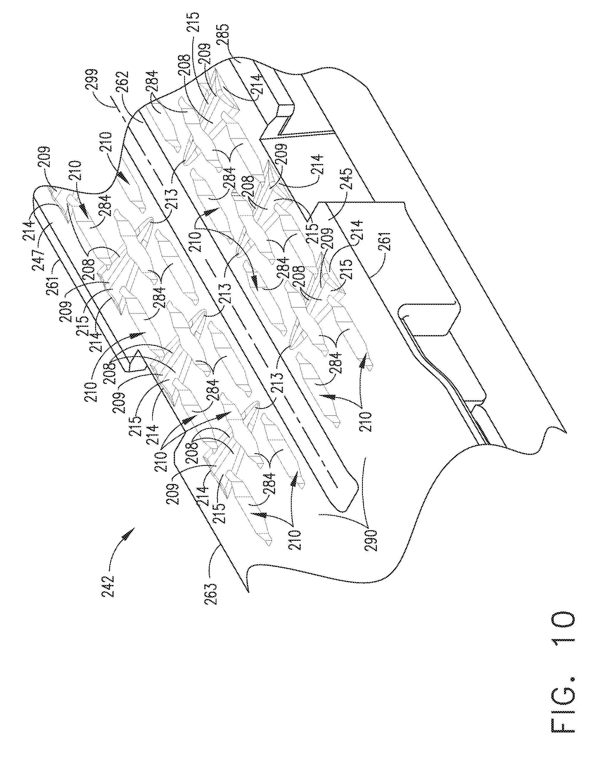
[0052] In various embodiments, referring now to FIG. 10, a staple cartridge, such as staple cartridge 242, for example, can comprise a cartridge body 285, a plurality of staple cavities 284 defined in the cartridge body 285, and a staple positioned in each of the staple cavities 284. In certain embodiments, the cartridge body 285 can further comprise a first side 245 comprising a first group of staple cavities 284, a second side 247 comprising a second group of staple cavities 284, and a cartridge deck 290. In various embodiments, the cartridge body 285 can further comprise a plurality of ridges, or bumps, 215 extending from the cartridge deck 290. In at least one such embodiment, each ridge 215 can extend transversely between a center, or middle, portion of the cartridge body 245 positioned adjacent to a knife slot 262 and a lateral portion of the cartridge body 245. More particularly, referring specifically to the first side 245 of the cartridge body 285, each ridge 215 can comprise a first end 213 positioned adjacent to the knife slot 262 and a second end 214 positioned adjacent to the first side 261 of the cartridge body 285. Similarly, referring now to the second side 247 of the cartridge body 285, each ridge 215 can comprise a first end 213 positioned adjacent to the knife slot 262 and a second end 214 positioned adjacent to the second side 263 of the cartridge body 285. In at least one embodiment, each ridge 215 can comprise a height measured from the deck 290 wherein, in at least one such embodiment, the height of each ridge 215 can vary along the length thereof. In certain embodiments, the second end 214 can be taller than the first end 213 and the height of each ridge 215 can taper between the second end 214 and the first end 213. In certain alternative embodiments, although not illustrated, the first end 213 of the ridge 215 can be taller than the second end 214. In at least one embodiment, the height of each ridge 215 can taper linearly, or at least substantially linearly, between the ends 213 and 214. In at least one such embodiment, the height of each ridge 215 can taper between a maximum height at the second end 214 down to no height at all at the first end 213. In certain embodiments, the height of each ridge 215 can vary geometrically between the ends 213 and 214. In certain alternative embodiments, referring now to FIG. 11, each ridge 215' can comprise a uniform height across the length thereof.
[0053] As described above, the inner ends 213 of the ridges 215 can be shorter than the outer ends 214 of the ridges 215. In various circumstances, as a result, the inner ends 213 can apply less pressure to the tissue clamped between an anvil and the staple cartridge 242 as compared to the outer ends 214. In various embodiments, as described above, each ridge 215 can extend transversely across the cartridge deck 290. In certain embodiments, each ridge 215 can extend along a ridge axis which transects a longitudinal axis 299 of the cartridge body 285. In at least one such embodiment, the ridge axes can be perpendicular, or at least substantially perpendicular, to the longitudinal axis 299. In various embodiments, the staple cavities 284 can be arranged in a plurality of rows, wherein each row of staple cavities 284 can be defined along a longitudinal axis which can be parallel to, or at least substantially parallel to, the longitudinal axis 299. In at least one embodiment, the ridge axes of the ridges 215 can extend in a direction which transect the longitudinal axes of the staple cavities 284. In at least one such embodiment, the ridge axes of the ridges 215 can extend in a direction which is perpendicular, or at least substantially perpendicular, to the longitudinal axes of the staple cavities 284. In various embodiments, referring again to FIG. 10, each ridge 215 can comprise a crest 209 and, in addition, sloped surfaces 208 extending between the crest 209 and the cartridge deck 290. In certain embodiments, each sloped surface 208 can comprise one or more flat surfaces, curved surfaces, concave surfaces, and/or convex surfaces, for example. In various embodiments, each ridge 215 can extend along a path which extends across one or more openings 210 of the staple cavities 284. In at least one such embodiment, such openings 210 can extend upwardly through the ridges 215. As the ridges 215 extend transversely across the cartridge deck 290, the ridges 215, similar to the ridges 115, can increase the strength and/or stiffness of the cartridge body 285.
[0054] In various embodiments, referring now to FIGS. 17 and 18, a staple cartridge, such as staple cartridge 642, for example, can comprise a cartridge body 685, a plurality of staple cavities 684 defined in the cartridge body 685, and a staple positioned in each of the staple cavities 684. In certain embodiments, the cartridge body 685 can further comprise a first side 645 comprising a first group of staple cavities 684, a second side 647 comprising a second group of staple cavities 684, and a cartridge deck 690. In various embodiments, the cartridge body 685 can further comprise a plurality of ridges, or bumps, 615 extending from the cartridge deck 690. In at least one such embodiment, each ridge 615 can extend in a longitudinal direction, wherein each ridge 615 can comprise a distal end 613 and a proximal end 614, wherein the distal end 613 of the ridge 615 can positioned closer to the distal end 643 of the cartridge body 685, and wherein the proximal end 614 of the ridge 615 can be positioned closer to the proximal end 641. In at least one embodiment, each ridge 615 can comprise a height measured from the deck 690 wherein, in at least one such embodiment, the height of each ridge 615 can vary along the length thereof. In certain embodiments, the proximal end 614 can be taller than the distal end 613 and the height of each ridge 615 can taper between the proximal end 614 and the distal end 613. In certain alternative embodiments, although not illustrated, the distal end 613 of the ridge 615 can be taller than the proximal end 614. In at least one embodiment, the height of each ridge 615 can taper linearly, or at least substantially linearly, between the ends 613 and 614. In at least one such embodiment, the height of each ridge 615 can taper between a maximum height at the proximal end 614 down to no height at all at the distal end 613. In certain embodiments, the height of each ridge 615 can vary geometrically between the ends 613 and 614. In certain alternative embodiments, each ridge 615 can comprise a uniform height across the length thereof.
[0055] As described above, the distal ends 613 of the ridges 615 can be shorter than the proximal ends 614 of the ridges 615. In various circumstances, as a result, the distal ends 613 can apply less pressure to the tissue clamped between an anvil and the staple cartridge 642 as compared to the proximal ends 614. In various embodiments, as described above, each ridge 615 can extend longitudinally across the cartridge deck 690. In certain embodiments, each ridge 615 can extend along a ridge axis which is parallel to, or at least substantially parallel to, a longitudinal axis 699 of the cartridge body 685. In various embodiments, the staple cavities 684 can be arranged in a plurality of rows, wherein each row of staple cavities 684 can be defined along a longitudinal axis which can be parallel to, or at least substantially parallel to, the ridge axes of ridges 615. In at least one embodiment, referring again to FIG. 18, each ridge 615 can comprise a ramped surface which can comprise one or more flat surfaces, curved surfaces, concave surfaces, and/or convex surfaces, for example. In at least one such embodiment, the bottom of the ramped surface can face distally which can facilitate the sliding of tissue across the staple cartridge 642 when the tissue is positioned in the end effector. In various embodiments, each ridge 615 can extend along a path which extends across one or more openings 610 of the staple cavities 684. In at least one such embodiment, such openings 610 can extend upwardly through the ridges 615. As the ridges 615 extend transversely across the cartridge deck 690, the ridges 615 can increase the strength and/or stiffness of the cartridge body 685.
[0056] In various embodiments, further to the above, a surgical staple can be comprised of titanium, such as titanium wire, for example. In certain embodiments, a surgical staple can be comprised of an alloy comprising titanium, aluminum, and/or vanadium, for example. In at least one embodiment, the surgical staple can be comprised of surgical stainless steel and/or an alloy comprised of cobalt and chromium, for example. In any event, the surgical staple can be comprised of metal, such as titanium, and a metal oxide outer surface, such as titanium oxide, for example. In various embodiments, the metal oxide outer surface can be coated with a material. In certain embodiments, the coating material can be comprised of polytetrafluoroethylene (PTFE), such as TEFLON.RTM., and/or a tetrafluoroethylene (TFE) such as ethylene-tetrafluoroethylene (ETFE), perfluroralkoxyethylene-tetrafluoroethylene (PFA), and/or Fluorinated Ethylene Propylene (FEP), for example. Certain coatings can comprise silicon. In various embodiments, such coating materials can prevent, or at least inhibit, further oxidation of the metal. In certain embodiments, the coating materials can provide one or more lubricious surfaces against which the anvil, or staple pockets, can contact the staples in order to reduce the friction force therebetween. In various circumstances, lower friction forces between the staples and the staple pockets can reduce the force required to deform the staples.
[0057] Although the various embodiments of the devices have been described herein in connection with certain disclosed embodiments, many modifications and variations to those embodiments may be implemented. Also, where materials are disclosed for certain components, other materials may be used. Furthermore, according to various embodiments, a single component may be replaced by multiple components, and multiple components may be replaced by a single component, to perform a given function or functions. The foregoing description and following claims are intended to cover all such modification and variations.
[0058] The devices disclosed herein can be designed to be disposed of after a single use, or they can be designed to be used multiple times. In either case, however, the device can be reconditioned for reuse after at least one use. Reconditioning can include any combination of the steps of disassembly of the device, followed by cleaning or replacement of particular pieces, and subsequent reassembly. In particular, the device can be disassembled, and any number of the particular pieces or parts of the device can be selectively replaced or removed in any combination. Upon cleaning and/or replacement of particular parts, the device can be reassembled for subsequent use either at a reconditioning facility, or by a surgical team immediately prior to a surgical procedure. Those skilled in the art will appreciate that reconditioning of a device can utilize a variety of techniques for disassembly, cleaning/replacement, and reassembly. Use of such techniques, and the resulting reconditioned device, are all within the scope of the present application.
[0059] Preferably, the invention described herein will be processed before surgery. First, a new or used instrument is obtained and if necessary cleaned. The instrument can then be sterilized. In one sterilization technique, the instrument is placed in a closed and sealed container, such as a plastic or TYVEK.RTM. bag. The container and instrument are then placed in a field of radiation that can penetrate the container, such as gamma radiation, x-rays, or high-energy electrons. The radiation kills bacteria on the instrument and in the container. The sterilized instrument can then be stored in the sterile container. The sealed container keeps the instrument sterile until it is opened in the medical facility.
[0060] While this invention has been described as having exemplary designs, the present invention may be further modified within the spirit and scope of the disclosure. This application is therefore intended to cover any variations, uses, or adaptations of the invention using its general principles. Further, this application is intended to cover such departures from the present disclosure as come within known or customary practice in the art to which this invention pertains.
[0061] Any patent, publication, or other disclosure material, in whole or in part, that is said to be incorporated by reference herein is incorporated herein only to the extent that the incorporated materials does not conflict with existing definitions, statements, or other disclosure material set forth in this disclosure. As such, and to the extent necessary, the disclosure as explicitly set forth herein supersedes any conflicting material incorporated herein by reference. Any material, or portion thereof, that is said to be incorporated by reference herein, but which conflicts with existing definitions, statements, or other disclosure material set forth herein will only be incorporated to the extent that no conflict arises between that incorporated material and the existing disclosure material.
* * * * *
D00000
D00001
D00002
D00003
D00004
D00005
D00006
D00007
D00008
D00009
D00010
D00011
D00012

D00013

D00014

D00015

D00016

D00017

D00018

D00019

D00020

XML
uspto.report is an independent third-party trademark research tool that is not affiliated, endorsed, or sponsored by the United States Patent and Trademark Office (USPTO) or any other governmental organization. The information provided by uspto.report is based on publicly available data at the time of writing and is intended for informational purposes only.
While we strive to provide accurate and up-to-date information, we do not guarantee the accuracy, completeness, reliability, or suitability of the information displayed on this site. The use of this site is at your own risk. Any reliance you place on such information is therefore strictly at your own risk.
All official trademark data, including owner information, should be verified by visiting the official USPTO website at www.uspto.gov. This site is not intended to replace professional legal advice and should not be used as a substitute for consulting with a legal professional who is knowledgeable about trademark law.