Product Display Units With Adjustable Widths
Illers; Marty ; et al.
U.S. patent application number 16/149296 was filed with the patent office on 2019-04-11 for product display units with adjustable widths. This patent application is currently assigned to Display Technologies, LLC. The applicant listed for this patent is Display Technologies, LLC. Invention is credited to Andrew Howard, Marty Illers.
| Application Number | 20190104863 16/149296 |
| Document ID | / |
| Family ID | 63762395 |
| Filed Date | 2019-04-11 |


View All Diagrams
| United States Patent Application | 20190104863 |
| Kind Code | A1 |
| Illers; Marty ; et al. | April 11, 2019 |
PRODUCT DISPLAY UNITS WITH ADJUSTABLE WIDTHS
Abstract
A product display unit includes a base, a first sidewall extending along a first side of the base, a second sidewall extending along an opposite, second side of the base, and a product support member that couples the base to the first sidewall and the second sidewall such that longitudinal movement of the product support member causes the first sidewall to transversely move relative to the second sidewall and such that transverse movement of the first sidewall relative to the second sidewall causes the product support member to longitudinally move.
| Inventors: | Illers; Marty; (Yonkers, NY) ; Howard; Andrew; (Windsor, CA) | ||||||||||
| Applicant: |
|
||||||||||
|---|---|---|---|---|---|---|---|---|---|---|---|
| Assignee: | Display Technologies, LLC Lake Success NY |
||||||||||
| Family ID: | 63762395 | ||||||||||
| Appl. No.: | 16/149296 | ||||||||||
| Filed: | October 2, 2018 |
Related U.S. Patent Documents
| Application Number | Filing Date | Patent Number | ||
|---|---|---|---|---|
| 62568379 | Oct 5, 2017 | |||
| Current U.S. Class: | 1/1 |
| Current CPC Class: | A47F 1/12 20130101; A47B 57/588 20130101; A47F 1/125 20130101; A47F 5/005 20130101; A47B 96/025 20130101; A47F 5/0093 20130101 |
| International Class: | A47F 5/00 20060101 A47F005/00; A47F 1/12 20060101 A47F001/12; A47B 57/58 20060101 A47B057/58 |
Claims
1. A product display unit comprising: a base extending from a first side to a second side in a transverse direction and from front to back in a longitudinal direction perpendicular to the transverse direction; a first sidewall extending along the first side of the base; a second sidewall extending along the second side of the base; and a product support member that couples the base to the first sidewall and the second sidewall such that longitudinal movement of the product support member causes the first sidewall to transversely move relative to the second sidewall and such that transverse movement of the first sidewall relative to the second sidewall causes the product support member to longitudinally move.
2. The product display unit according to claim 1, wherein the first sidewall and the second sidewall move toward each other as the product support member is moved toward the back of the base and away from each other as the product support member is moved toward the front the base.
3. The product display unit according to claim 1, further comprising an end member coupled to the front of the base and configured to prevent products from falling off the product support member.
4. The product display unit according to claim 3, wherein the first sidewall has a front end, and wherein the end member moves toward the front end as the product support member is moved toward the front of the base and away from the front end as the product support member is moved toward the back of the base.
5. The product display unit according to claim 1, wherein the first sidewall has a leg transversely extending toward the second sidewall and the second sidewall has a leg transversely extending toward the first sidewall, and wherein the leg of the first sidewall and the leg of the second sidewall are vertically positioned between the base and the product support member.
6. The product display unit according to claim 5, further comprising a first pin and a second pin that couple the product support member to the base; wherein the leg of the first sidewall has a first slot in which the first pin is received and the leg of the second sidewall has a second slot in which the second pin is received; and wherein as the product support member is moved the first pin slides in the first slot and the second pin slides in the second slot.
7. The product display unit according to claim 6, wherein the base has a center axis longitudinally extending along the base, and wherein the first slot and the second slot transversely extend relative to the center axis.
8. The product display unit according to claim 7, wherein the first slot and the center axis form a 30 degree angle, and wherein the second slot and the center axis form a 30 degree angle.
9. The product display unit according to claim 5, wherein the base has a first arm transversely extending toward the first sidewall and a second arm transversely extending toward the second sidewall; and wherein as the product support member is moved the first arm slides along the leg of the first sidewall and the second arm slides with the leg of the second sidewall.
10. The product display unit according to claim 9, wherein the base has a center axis longitudinally extending along the base, and wherein the leg of the first sidewall, the leg of the second sidewall, the first arm, and the second arm transversely extend relative to the center axis.
11. The product display unit according to claim 10, wherein the leg of the first sidewall, the leg of the second sidewall, the first arm, and the second arm each form a 30 degree angle with the center axis.
12. The product display unit according to claim 9, wherein the leg of the first sidewall is one of a plurality of legs spaced part along the first sidewall and extending toward the second sidewall; wherein the leg of the second sidewall is one of a plurality of legs spaced part along the second sidewall and extending toward the first sidewall; wherein the first arm is one of a first plurality of arms spaced apart along the base and extending toward the first sidewall; wherein the second arm is one of a second plurality of arms spaced apart along the base and extending toward the second sidewall; and wherein the legs of the plurality of legs of the first sidewall are interdigitated with the arms of the first plurality of arms and the legs of the plurality of legs of the second sidewall are interdigitated with the arms of the second plurality of arms.
13. The product display unit according to claim 12, wherein the base has a center axis longitudinally extending along the base, and wherein the legs of the plurality of legs of the first sidewall, the legs of the plurality of legs of the second sidewall, the arms of the first plurality of arms, and the arms of the second plurality of arms transversely extend relative to the center axis.
14. The product display unit according to claim 13, wherein each leg of the plurality of legs of the first sidewall, each leg of the plurality of legs of the second sidewall, each arm of the first plurality of arms, and each arm of the second plurality of arms from a 30 degree angle with the center axis.
15. The product display unit according to claim 14, wherein the legs of the plurality of legs of the first sidewall, the legs of the plurality of legs of the second sidewall, the arms of the first plurality of arms, and the arms of the second plurality of arms form a herringbone pattern.
16. A product display unit comprising: a base extending from a first side to a second side in a transverse direction and from front to back in a longitudinal direction perpendicular to the transverse direction; a first sidewall extending along the first side of the base; a second sidewall extending along the second side of the base; and a product support member that couples the base to the first sidewall and the second sidewall such that as one of the first sidewall and the second sidewall transversely moves the product support member is longitudinally moved and as the product support member longitudinally moves at least one of the first sidewall and the second sidewall is transversely moved.
17. The product display unit according to claim 16, wherein the first sidewall has a leg transversely extending toward the second sidewall and the second sidewall has a leg transversely extending toward the first sidewall, and wherein the leg of the first sidewall and the leg of the second sidewall are vertically positioned between the base and the product support member.
18. The product display unit according to claim 17, wherein the base has a first arm transversely extending toward the first sidewall and a second arm transversely extending toward the second sidewall; and wherein as the product support member is moved the first arm slides along the leg of the first sidewall and the second arm slides along the leg of the second sidewall.
19. The product display unit according to claim 18, wherein the leg of the first sidewall is one of a plurality of legs spaced part along the first sidewall and extending toward the second sidewall; wherein the leg of the second sidewall is one of a plurality of legs spaced part along the second sidewall and extending toward the first sidewall; wherein the first arm is one of a first plurality of arms spaced apart along the base and extending toward the first sidewall; wherein the second arm is one of a second plurality of arms spaced apart along the base and extending toward the second sidewall; and wherein the legs of the plurality of legs of the first sidewall are interdigitated with the arms of the first plurality of arms and the legs of the plurality of legs of the second sidewall are interdigitated with the arms of the second plurality of arms.
20. The product display unit according to claim 19, wherein the legs of the plurality of legs of the first sidewall, the legs of the plurality of legs of the second sidewall, the arms of the first plurality of arms, and the arms of the second plurality of arms form a herringbone pattern.
Description
CROSS-REFERENCE TO RELATED APPLICATION
[0001] The present application is based on and claims priority to U.S. Provisional Patent Application No. 62/568,379 filed Oct. 5, 2017, the disclosure of which is incorporated herein by reference.
FIELD
[0002] The present disclosure relates to product display units for dispensing products, and specifically to product display units with adjustable widths.
BACKGROUND
[0003] The following U.S. patents are incorporated herein by reference in entirety.
[0004] U.S. Pat. No. 9,392,882 discloses a merchandising system for a displaying a plurality of products. The system has a base and a pusher member. The base includes a product-supporting surface and a track disposed beneath the product-supporting surface. The base defines a longitudinal axis. The pusher member is disposed in mechanical cooperation with the base and is configured to slide longitudinally with respect to the base. The pusher member includes a base-contacting surface and a plurality of legs downwardly depending from the base-contacting surface. Each of the plurality of legs is configured to mechanically engage the track. The track includes a discontinuity to enable the legs of the pusher member to selectively mechanically engage the track.
[0005] U.S. Pat. No. 9,713,395 discloses a merchandising system with a track and a pusher. The track defines a longitudinal axis and includes a plurality of tabs. Each tab of the plurality of tabs includes a width that is perpendicular to the longitudinal axis. The pusher member is configured to slide longitudinally with respect to the track. The pusher member includes at least one leg configured to mechanically engage the track. The track includes a discontinuity to facilitate removal of the pusher member from the track. The discontinuity includes at least one other tab having a width less than a width of an adjacent tab of the plurality of tabs.
[0006] U.S. Pat. No. 10,045,637 discloses a product display unit that includes a first track and a second track. The first track defines a longitudinal axis and is configured to support products thereon. The first track is configured to guide the products along the longitudinal axis. The second track is configured to support products thereon. A first portion of the second track is configured to guide the products in a first direction that is disposed at an angle with respect to the longitudinal axis. A second portion of the second track is configured to guide the products in a second direction that is parallel to the longitudinal axis.
SUMMARY
[0007] This Summary is provided to introduce a selection of concepts that are further described below in the Detailed Description. This Summary is not intended to identify key or essential features of the claimed subject matter, nor is it intended to be used as an aid in limiting the scope of the claimed subject matter.
[0008] In certain examples, a product display unit includes a base extending from a first side to a second side in a transverse direction and from front to back in a longitudinal direction perpendicular to the transverse direction, a first sidewall extending along the first side of the base, a second sidewall extending along the second side of the base, and a product support member that couples the base to the first sidewall and the second sidewall such that longitudinal movement of the product support member causes the first sidewall to transversely move relative to the second sidewall and such that transverse movement of the first sidewall relative to the second sidewall causes the product support member to longitudinally move.
BRIEF DESCRIPTION OF THE DRAWINGS
[0009] The present disclosure is described with reference to the following Figures. The same numbers are used throughout the Figures to reference like features and like components.
[0010] FIG. 1 is a top perspective view of an example product display unit with six tracks.
[0011] FIG. 2 is an exploded view of two tracks of the product display unit of FIG. 1.
[0012] FIG. 3 is a perspective view of a base.
[0013] FIG. 4 is a top plan view of the base of FIG. 3.
[0014] FIG. 5 is a top perspective view of a left-side sidewall.
[0015] FIG. 6 is a top plan view of the left-side sidewall of FIG. 5.
[0016] FIG. 7 is a top perspective view of a right-side sidewall.
[0017] FIG. 8 is a top plan view of the right-side sidewall of FIG. 7.
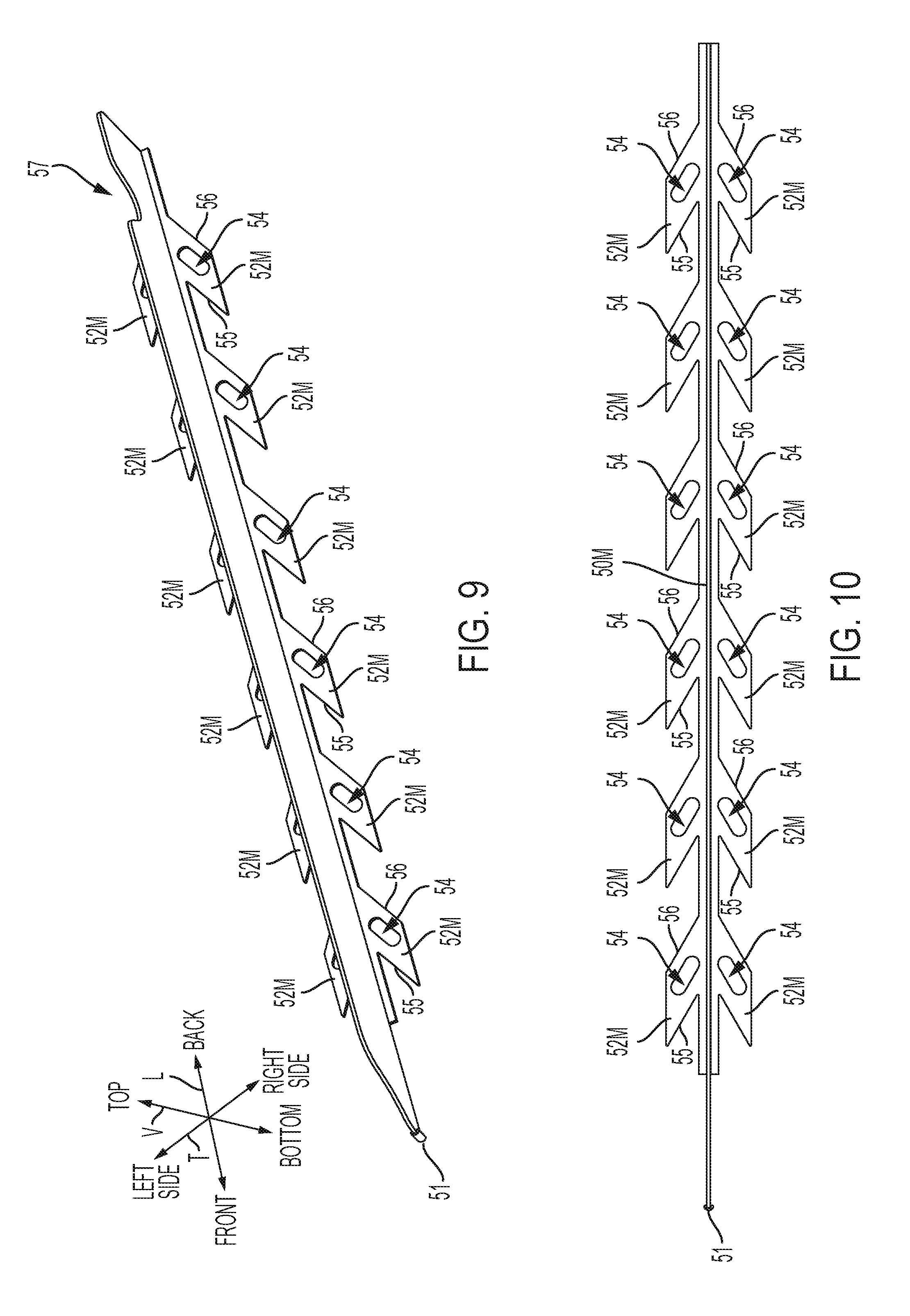
[0018] FIG. 9 is a top perspective view of a middle sidewall.
[0019] FIG. 10 is a top plan view of the middle sidewall of FIG. 9.
[0020] FIG. 11 is a top perspective view of a track member.
[0021] FIG. 12 is a top plan view of the track member of FIG. 11.
[0022] FIG. 13 is a bottom plan view of the track member of FIG. 11.
[0023] FIG. 14 is a top perspective view of a spine.
[0024] FIG. 15 is a top plan view of the spine of FIG. 14.
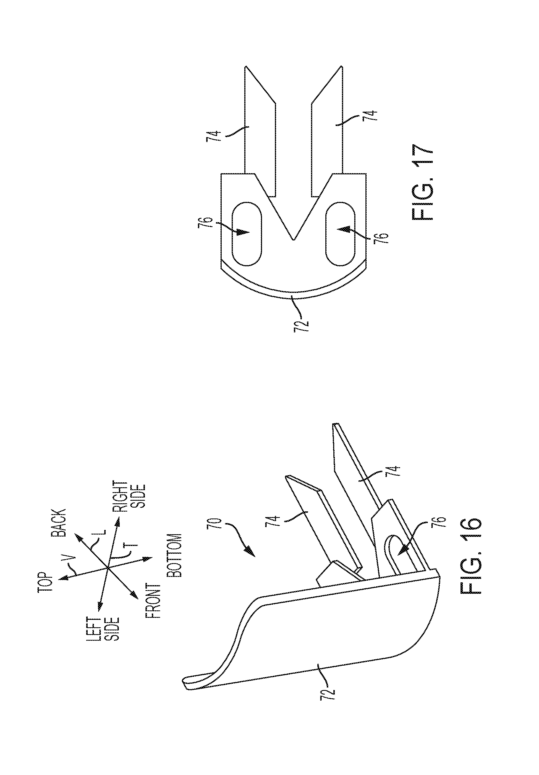
[0025] FIG. 16 is a top perspective view of an end member.
[0026] FIG. 17 is a top plan view of the end member of FIG. 16.
[0027] FIG. 18 is a cross-sectional view of a pin of the track member received into a slot of a leg and a hole of the base.
[0028] FIG. 19 is a cross-sectional view of a finger of the track member received into a slot of the spine and a slot of the base.
[0029] FIG. 20 is a top perspective view of a product display unit with two tracks each in a first position. The track member is removed to expose the spine and the sidewalls.
[0030] FIG. 21 is a view like FIG. 20 with each track in a second position.
[0031] FIG. 22 is a top perspective view of a product display unit with two tracks and two pusher assemblies.
[0032] FIG. 23 is an enlarged view of a bottom surface of a track member with a first end of a biasing member of the pusher assembly coupled to a boss.
DETAILED DISCLOSURE
[0033] Conventional product display units are used in retail stores for dispensing products to customers. These product display units are located on shelving units, such as wire-form shelves in refrigerated cabinets. Products, such as soda bottles, milk jugs, and juice cans, are located on the product display unit in tracks and can be removed by a customer from the front of the product display unit. Upon removal, the remaining products on the product display unit are caused to move under force of gravity or a pusher assembly toward the front of the product display unit.
[0034] The type, size, and shape Fof the products placed on the product display unit can vary. For example, the products placed on the product display unit may include 12-ounce soda cans, 20-ounce soda bottles, 40-ounce glass bottles, rectangular food product such as cheese, and the like. In addition, products may be moved from one product display unit or track to another as customer demand changes. Accordingly, the present inventors have realized that there is a need for improved product displays units with adjustable widths that permit the width of the product display units and/or the tracks to be adjusted based on the size and shape of the products placed on the product display unit.
[0035] FIG. 1 depicts an example product display unit 20 according to the present disclosure. The product display unit 20 is positioned on a shelf 16 (depicted in dashed lines) of a shelving unit (not shown). The product display unit 20 includes one or more tracks 22, each of which holds one or more products (not shown). Each track 22 extends from front to back in a longitudinal direction (see arrow L) and from side (e.g. left side) to side (e.g. right side) in a transverse direction (see arrow T) that is perpendicular to the longitudinal direction. The number of tracks 22 in the product display unit 20 can vary. In the illustrated example, the product display unit 20 has six tracks 22. The tracks 22 are removably coupled to each other with fasteners (e.g. bolts, dove-tail connections, rivets, detents, and projections) such that tracks 22 can be added or removed from the product display unit 20.
[0036] FIG. 2 is an exploded view of two tracks 22 of a product display unit 20. Each track 22 has a base 40 which rests on the shelf 16 (FIG. 1). The base 40 is coupled to a spine 33. An end member 70 is coupled to the base 40 and is configured to prevent products from inadvertently moving over the front of the product display unit 20. Sidewalls, namely a left-side sidewall 50L, middle sidewall 50M, and right-side sidewall 50R, extend along the sides of the tracks 22 and the sides of the base 40 to prevent products from inadvertently moving off the product support member 25 or into moving into adjacent tracks 22. The left-side sidewall 50L extends along the left side of the product display unit 20 and the leftmost track 22, the middle sidewall 50M separates the tracks 22, and the right-side sidewall 50R extends along the right side of the product display unit 20 and the rightmost track 22. Each track 22 also includes a product support member 25 on which the products are supported and moved. The product support member 25 couples adjacent sidewalls 50L, 50M, 50R to the base 40 to form the adjustable track 22.
[0037] The components of the track 22 briefly mentioned above are described in greater detail hereinbelow with reference to FIGS. 3-17. FIGS. 3-4 depict the base 40 in greater detail. The base 40 extends along a center axis 41 of the track 22 (see also FIG. 1) and has multiple cutouts 42, slots 44, and holes 46 which receive and engage with other components of the track 22. The base 40 is coupled to a spine 33 (FIG. 2) which is described hereinbelow. Note that the base 40 and the spine 33 are shown in FIG. 2 as separate components and separable from each other, however, in certain examples the base 40 and the spine 33 can be integral with each other or formed together as a unitary piece such that features of the spine 33 described hereinbelow are included with the base 40. In other examples, the spine 33 is plug welded to the base 40 such that the base 40 and the spine 33 are fixedly coupled together. The base 40 extends from a first side to a second side in the transverse direction and from front to back in the longitudinal direction.
[0038] FIGS. 5-10 depict the sidewalls in greater detail. In particular, FIGS. 5-6 depict the left-side sidewall 50L, FIGS. 7-8 depict the middle sidewall 50M, and FIGS. 9-10 depict the right-side sidewall 50R. Note that the right-side sidewall 50R is a mirror image of the left-side sidewall 50L. Each sidewall 50L, 50M, 50R extends vertically in the vertical direction (see arrow V) toward the top of the product display unit 20 (FIG. 1) and in the longitudinal direction along one or more sides of the tracks 22 (FIGS. 1-2). Each sidewall 50L, 50M, 50R has a front end 51 and at least one leg 52L, 52M, 52R extending in the transverse direction toward the adjacent sidewall 50L, 50M, 50R. For example, the left-side sidewall 50L has a plurality of legs 52L (FIGS. 5-6) transversely extending toward the middle sidewall 50M (see FIG. 20), the right-side sidewall 50R has a plurality of legs 52R (FIGS. 7-8) transversely extending toward the middle sidewall 50M (see FIG. 20), and the middle sidewall 52M has a plurality of legs 52M (FIGS. 9-10) transversely extending toward the left-side sidewall 50L and a plurality of legs 52M transversely extending toward the right-side sidewall 50R (see FIG. 20). Each leg 52L, 52M, 52R transversely extends toward the adjacent sidewall 50L, 50M, 50R at an angle relative to the center axis 41 (see FIG. 20). The angle formed between the leg 52L, 52M, 52R and the center axis 41 can vary, such as 45 degrees or 30 degrees. Each leg 52L, 52M, 52R has a first or front edge 55, an opposite second or back edge 56, and a slot 54 in which a pin 31 is received and slides (described further herein). The slots 54 transversely extend relative to the center axis 41 (e.g. each slot 54 and the center axis 41 form an angle such as a 30 degree angle). When the track 22 is assembled, the legs 52L, 52M, 52R are positioned vertically between the base 40 and the product support member 25 (see FIG. 18) (e.g. the legs 52L, 52M, 52R are sandwiched between the base 40 and the product support member 25). Each sidewall 50L, 50M, 50R has a cutout 57 in which an employee's hand can be placed to apply an amount of resistance to the product display unit 20 when the sidewalls 50L, 50M, 50R and the product support member 25 are moved relative to each other, as described herein.
[0039] A person having ordinary skill in the art will recognize that number and types of the sidewalls used in the product display unit can vary. For example, separate two-track units may be connected in side-by-side orientation to form the product display unit 20 such that right-side sidewalls 50R are immediately next to left-side sidewalls 50L, as shown in FIG. 1. In other examples, the tracks 22 of the product display unit 20 are separated by middle sidewalls 50M and only a single left-side sidewall 50L and a single right-side sidewall 50R are included at the sides of the product display unit 20.
[0040] FIGS. 11-13 depict the product support member 25 in greater detail. The product support member 25 has a top support surface 28 and an opposite, bottom surface 30. Products placed on the product display unit 20 contact and are moved along the top support surface 28. A fin 29 transversely extends away from the top support surface 28 in the vertical direction. The fin 29 is positioned at the back of the product support member 25. The fin 29 can be engaged by the employee to longitudinally move product support member 25. The fin 29 also prevents products from falling off the back of the product support member 25. The product support member 25 has one or more pins 31 vertically extending away from the bottom surface 30 that are received into the slots 54 of the legs 52L, 52M, 52R (see FIG. 6) and/or the holes 46 in the base 40 (see FIG. 4) (see also FIG. 18). The pins 31 are arranged in pairs such that a pin 31 is on either side of the center axis 41. The product support member 25 also has one or more fingers 32 which extend through slots 37 in the spine 33 (described herein) and/or the slots 44 of base 40 (FIG. 4) (see also FIG. 19) to couple the product support member 25 to the base 40 and the sidewalls 50L, 50M, 50R. In certain examples, the product support member 25 and the base 40 (and spine 33) move together when coupled to each other.
[0041] Referring to FIGS. 14-15 the spine 33 has a plurality of arms 34 extending in the transverse direction toward adjacent sidewalls 50L, 50M, 50R, at an angle relative to the center axis 41 (see FIG. 20). The angle formed between the arm 34 and the center axis 41 can vary, such as 45 degrees or 30 degrees. In certain examples, the angle formed between the arm 34 and the center axis 41 is equal to the angle formed between the leg 52 and the center axis 41. Each arm 34 has a first or front edge 35 and an opposite second or back edge 36. The spine 33 includes one or more slots 37 that receive the fingers 32 of the product support member 25. When the product support member 25 is coupled to the base 40 and the spine 33 and the sidewalls 50L, 50M, 50R (see FIG. 20), the arms 34 interlock or are interdigitated with the legs of adjacent sidewalls 50L, 50M, 50R. For example with reference to FIG. 20, the arms 34 extending toward the left-side sidewall 50L are interdigitated with the legs 52L of the left-side sidewall 50L and the arms 34 extending toward the middle sidewall 50M are interdigitated with the legs 52M of the middle sidewall 50L. When assembled the arms 34 and the legs 52L, 52M, 52R form a herringbone pattern.
[0042] FIGS. 16-17 depict the end member 70 in greater detail. The end member 70 has an end wall 72 that extends toward the top of the product display unit 20 in the vertical direction (see FIG. 1). Forks 74 extend in the longitudinal direction away from the end wall 72. The forks 74 are slidably received and retained in the cutouts 42 of the base 40 (FIG. 3) when the product support member 25 couples to the base 40 and the sidewalls 50L, 50M, 50R. The end member 70 includes slots 76 in which the front-most pins 31 of the product support member 25 are slidably received. The end member 70 can contact and be braced against a lip 17 of the shelf 16 (both the lip 17 and the shelf 16 are shown in dashed lines on FIG. 1).
[0043] The components of the track 22 are coupled or assembled together as described hereinbelow with reference to FIGS. 18-19. Referring to FIG. 18, a cross-sectional view of an example pin 31 relative to other components of the track 22 is depicted. To assemble the track 22, the pins 31 of the product support member 25 (see also FIG. 13) are received into the slots 54 of the legs 52L, 52M, 52R (see also FIGS. 5, 7, and 9) and the holes 46 of the base 40 (see also FIG. 4). The two front-most pins 31 are also received into the slots 76 of the end member 70 (FIG. 17) and the forks 74 of the end member 70 (FIG. 17) are received and restrained in the cutouts 42 defined by the base 40 (FIG. 4). Referring now to FIG. 19, a cross-sectional view of an example finger 32 relative to the other components of the track 22 is depicted. As the track 22 is assembled, the fingers 32 of the product support member 25 (see also FIG. 13) are received in the slots 37 of the spine 33 (also FIG. 14) and the slots 44 of the base 40 (see also FIG. 4). When the track 22 is fully assembled, the arms 34 of the spine 33 are interdigitated with the legs 52L, 52M, 52R of the adjacent sidewalls 50L, 50M, 50R (see FIG. 19) and the width of each track 22 can be easily adjusted, as described hereinbelow.
[0044] Now referring to FIGS. 20-21, each track 22 is adjustable into and between a first or closed position (FIG. 20) in which the track 22 has a first or minimum width W1 and a second or open position (FIG. 21) in which the track 22 has a second or maximum width W2 which is greater than the first width W1. The track 22 can be moved into and the between the first and second positions together or independently. The track 22 can also be adjusted to any intermediate position between the first position (FIG. 20) and the second position (FIG. 21). Note that the product support member 25 (see FIG. 11) have been removed from FIGS. 20-21 to expose the legs 52L, 52M, 52R of the sidewalls 50L, 50M, 50R and the arms 34 of the spine 33.
[0045] To move the track 22 into and between the first position (FIG. 20) and the second position (FIG. 21), the product support member 25 (FIG. 2) is moved by the employee in the longitudinal direction such that the adjacent sidewalls 50L, 50M, 50R (e.g. the left-side sidewall 50L and the middle sidewall 50M) move relative to each other in the transverse direction. That is, longitudinal movement of the product support member 25 causes a first adjacent sidewall 50L, 50M, 50R to transversely move relative to an opposite second adjacent sidewall 50L, 50M, 50R.
[0046] Specifically, as the product support member 25 longitudinally moves in a direction toward the front of the base 40 the first adjacent sidewall 50L, 50M, 50R and the second adjacent sidewall 50L, 50M, 50R are moved away from each other and the track 22 moves away from the first position (FIG. 20) toward the second position (FIG. 21). The longitudinal movement of the product support member 25 in a direction toward the front of the base 40 causes the arms 34 of the spine 33 to slide along and engage with or act on the legs 52L, 52M, 52R of the sidewalls 50L, 50M, 50R such that the sidewalls 50L, 50M, 50R move away from each other and the pins 31 (FIG. 13) slide in the slots 54 of the legs 52L, 52M, 52R (e.g. the arms 34 cam the legs 52L, 52M, 52R thereby causing the sidewalls 50L, 50M, 50R to laterally move outwardly). In particular, the front edges 35 of the arm 34 act on and slide along the back edge 56 of the legs 52L, 52M, 52R. As the track 22 is moved from the first position (FIG. 20) to the second position (FIG. 21), the width of the track 22 increases. Referring to FIG. 21, the legs 52L, 52M, 52R are spaced apart from the center axis 41 when the track 22 is in the second position. In addition, the end member 70 is also moved in the longitudinal direction as the product support member 25 is moved in a direction toward the front of the base 40 such that the distance between the end member 70 and the front ends 51 of the legs 52L, 52M, 52R decreases. That is, the end member 70 and the front ends 51 are spaced apart a first distance D1 (FIG. 20) when the track 22 is in the first position (FIG. 20) and a second distance D2 (FIG. 21) when the track 22 is in the second position (FIG. 21). The end member 70 may also freely move or "float" relative to the product support member 25 as the forks 74 (FIG. 16) slide in the cutouts 42 (FIG. 3) of the base 40. In certain examples, the end member 70 moves relative to the base 40 as the track 22 is moved into and between the first position (FIG. 20) and the second position (FIG. 21) such that the end wall 72 of end member 70 is consistently contacting or resting on the lip 17 of the shelf 16 (FIG. 1).
[0047] Alternatively, as the product support member 25 longitudinally moves in a direction toward the back of the base 40 the first adjacent sidewall 50L, 50M, 50R and the second adjacent sidewall 50L, 50M, 50R move toward from each other and the track 22 moves away from the second position (FIG. 21) toward the first position (FIG. 20). The longitudinal movement of the product support member 25 in a direction toward the back of the base 40 causes the arms 34 of the spine 33 to engage with or act on the legs 52L, 52M, 52R of the sidewalls 50L, 50M, 50R such that the sidewalls 50L, 50M, 50R move toward each other and the pins 31 (FIG. 13) slide in the slots 54 of the legs 52L, 52M, 52R. In particular, the back edges 36 of the arms 34 act on and slide along the front edges 55 of the legs 52L, 52M, 52R. As the track 22 is moved from the second position (FIG. 21) to the first position (FIG. 20), the width of the track 22 decrease. The end member 70 is moved in the longitudinal direction as the product support member 25 is moved in a direction toward the back of the base 40 such that the distance between the end member 70 and the front end 51 of the legs 52L, 52M, 52R increases. The legs 52L, 52M, 52R are next to the center axis 41 when the track 22 is in the first position (FIG. 20) and spaced apart from the center axis 41 when the track 22 is the second position (FIG. 21).
[0048] The track 22 can also be moved into and the between the first position (FIG. 20) and the second position (FIG. 21) by moving the sidewalls 50L, 50M, 50R relative to each other. For example, to move the track 22 into and between the first position (FIG. 20) and the second position (FIG. 21), at least one of the sidewalls 50L, 50M, 50R is moved by the employee in the transverse direction such that the product support member 25 moves in the longitudinal direction. That is, transverse movement of one of the sidewall 50L, 50M, 50R causes product support member 25 to longitudinally move.
[0049] In one specific example, when the employee transversely pulls one the sidewalls 50L, 50M, 50R away from the center axis 41 the product support member 25 is moved in the longitudinal direction toward the front of the base 40 and the track 22 is moved toward the second position (FIG. 21). Alternatively, when the employee transversely pushes one the sidewalls 50L, 50M, 50R toward from the center axis 41 the product support member 25 is moved in the longitudinal direction toward the back of the base 40 and the track is moved toward the first position (FIG. 20).
[0050] Referring to FIGS. 22-23, in certain examples a pusher assembly 100 can be provided at each track 22 and is coupled to the product support member 25. The pusher assembly is configured to push or urge products along the product support member 25 toward the front of the product display unit 20 as products are removed from the front of the product display unit 20 by the customer. The pusher assembly 100 is also configured to move toward the back of the product display unit 20 as products are restocked into the tracks 22. The pusher assembly 100 includes a biasing member 110 coupled to a base member 102. The biasing member 110 has a first end 111 (FIG. 23) coupled to the bottom surface 30 of the product support member 25. In the example depicted, the biasing member 110 is a spring (e.g. constant force spring). Referring specifically to FIG. 23, the first end 11 of the biasing member extends through a hole in the product support member 25 and coupled to a boss 114 that extends away from the bottom surface 30. A tab 116 is provided on the bottom surface 30 to restrain the first end 11 on the boss 114. Reference is made to above-incorporated U.S. Pat. No. 9,392,882 for description of a conventional pusher assembly.
[0051] In certain examples, a product display unit includes a base extending from a first side to a second side in a transverse direction and from front to back in a longitudinal direction perpendicular to the transverse direction, a first sidewall extending along the first side of the base, a second sidewall extending along the second side of the base, and a product support member that couples the base to the first sidewall and the second sidewall such that longitudinal movement of the product support member causes the first sidewall to transversely move relative to the second sidewall and such that transverse movement of the first sidewall relative to the second sidewall causes the product support member to longitudinally move. The first sidewall and the second sidewall move toward each other as the product support member is moved toward the back of the base and away from each other as the product support member is moved toward the front the base. An end member coupled to the front of the base and configured to prevent products from falling off the product support member. The first sidewall has a front end, and the end member moves toward the front end as the product support member is moved toward the front of the base and away from the front end as the product support member is moved toward the back of the base. The first sidewall has a leg transversely extending toward the second sidewall and the second sidewall has a leg transversely extending toward the first sidewall. The leg of the first sidewall and the leg of the second sidewall are vertically positioned between the base and the product support member. A first pin and a second pin couple the product support member to the base, and the leg of the first sidewall has a first slot in which the first pin is received and the leg of the second sidewall has a second slot in which the second pin is received. As the product support member is moved, the first pin slides in the first slot and the second pin slides in the second slot. The base has a center axis longitudinally extending along the base, and the first slot and the second slot transversely extend relative to the center axis. In certain examples, the first slot and the center axis form a 30 degree angle and the second slot and the center axis form a 30 degree angle. The base has a first arm transversely extending toward the first sidewall and a second arm transversely extending toward the second sidewall. As the product support member is moved the first arm slides along the leg of the first sidewall and the second arm slides with the leg of the second sidewall. The leg of the first sidewall, the leg of the second sidewall, the first arm, and the second arm transversely extend relative to the center axis. In certain examples, the leg of the first sidewall, the leg of the second sidewall, the first arm, and the second arm each form a 30 degree angle with the center axis.
[0052] In certain examples, the leg of the first sidewall is one of a plurality of legs spaced part along the first sidewall and extending toward the second sidewall, the leg of the second sidewall is one of a plurality of legs spaced part along the second sidewall and extending toward the first sidewall, the first arm is one of a first plurality of arms spaced apart along the base and extending toward the first sidewall, and the second arm is one of a second plurality of arms spaced apart along the base and extending toward the second sidewall. The legs of the plurality of legs of the first sidewall are interdigitated with the arms of the first plurality of arms and the legs of the plurality of legs of the second sidewall are interdigitated with the arms of the second plurality of arms. The plurality of legs of the first sidewall, the legs of the plurality of legs of the second sidewall, the arms of the first plurality of arms, and the arms of the second plurality of arms transversely extend relative to the center axis. In certain examples, the each leg of the plurality of legs of the first sidewall, each leg of the plurality of legs of the second sidewall, each arm the first plurality of arms, and each arm second plurality of arms from a 30 degree angle with the center axis. The legs of the plurality of legs of the first sidewall, the legs of the plurality of legs of the second sidewall, the arms of the first plurality of arms, and the arms of the second plurality of arms form a herringbone pattern.
[0053] In certain examples, the product display unit includes a base extending from a first side to a second side in a transverse direction and from front to back in a longitudinal direction perpendicular to the transverse direction, a first sidewall extending along the first side of the base, a second sidewall extending along the second side of the base, and a product support member that couples the base to the first sidewall and the second sidewall such that as one of the first sidewall and the second sidewall transversely moves the product support member is longitudinally moved and as the product support member longitudinally moves at least one of the first sidewall and the second sidewall is transversely moved.
[0054] In the present description, certain terms have been used for brevity, clarity, and understanding. No unnecessary limitations are to be inferred therefrom beyond the requirement of the prior art because such terms are used for descriptive purposes only and are intended to be broadly construed. The different apparatuses and systems described herein may be used alone or in combination with other apparatuses and systems. Various equivalents, alternatives, and modifications are possible within the scope of the appended claims.
* * * * *
D00000
D00001
D00002
D00003
D00004
D00005
D00006
D00007
D00008
D00009
D00010
D00011
D00012

D00013

XML
uspto.report is an independent third-party trademark research tool that is not affiliated, endorsed, or sponsored by the United States Patent and Trademark Office (USPTO) or any other governmental organization. The information provided by uspto.report is based on publicly available data at the time of writing and is intended for informational purposes only.
While we strive to provide accurate and up-to-date information, we do not guarantee the accuracy, completeness, reliability, or suitability of the information displayed on this site. The use of this site is at your own risk. Any reliance you place on such information is therefore strictly at your own risk.
All official trademark data, including owner information, should be verified by visiting the official USPTO website at www.uspto.gov. This site is not intended to replace professional legal advice and should not be used as a substitute for consulting with a legal professional who is knowledgeable about trademark law.