Ultra-low Latency Audio Over Bluetooth
HARIHARAN; Sriram ; et al.
U.S. patent application number 16/146571 was filed with the patent office on 2019-04-04 for ultra-low latency audio over bluetooth. The applicant listed for this patent is Apple Inc.. Invention is credited to Sreeraman ANANTHARAMAN, Sriram HARIHARAN, Ran IRONY, Alon PAYCHER, Robert D. SILFVAST.
| Application Number | 20190104424 16/146571 |
| Document ID | / |
| Family ID | 65896310 |
| Filed Date | 2019-04-04 |


View All Diagrams
| United States Patent Application | 20190104424 |
| Kind Code | A1 |
| HARIHARAN; Sriram ; et al. | April 4, 2019 |
ULTRA-LOW LATENCY AUDIO OVER BLUETOOTH
Abstract
Methods and apparatus for communicating audio packets with ultra-low latency at high data rates from an audio source device to one or more audio output devices over a wireless personal area network (WPAN) connection, such as via a Bluetooth connection. Latency is reduced by using time-efficient audio coding and decoding, limited retransmissions, reduced time and frequency of acknowledgements, and by combining Bluetooth Classic (BTC) packets for downlink audio and downlink control with Bluetooth Low Energy (BTLE) packets for uplink control, uplink acknowledgements, and inter-device wireless communication. The number of retransmissions and packet concealments per frame cycle can be limited to an upper threshold number to satisfy a low latency requirement.
| Inventors: | HARIHARAN; Sriram; (San Jose, CA) ; PAYCHER; Alon; (Beit Hananya, IL) ; IRONY; Ran; (Hod Hasharon, IL) ; ANANTHARAMAN; Sreeraman; (Los Altos, CA) ; SILFVAST; Robert D.; (Belmont, CA) | ||||||||||
| Applicant: |
|
||||||||||
|---|---|---|---|---|---|---|---|---|---|---|---|
| Family ID: | 65896310 | ||||||||||
| Appl. No.: | 16/146571 | ||||||||||
| Filed: | September 28, 2018 |
Related U.S. Patent Documents
| Application Number | Filing Date | Patent Number | ||
|---|---|---|---|---|
| 62565416 | Sep 29, 2017 | |||
| Current U.S. Class: | 1/1 |
| Current CPC Class: | H04W 84/18 20130101; H04R 2420/07 20130101; H04R 3/12 20130101; H04L 5/0055 20130101; H04L 1/1621 20130101; H04L 43/0847 20130101; H04W 24/02 20130101; H04W 84/12 20130101; H04L 1/1867 20130101 |
| International Class: | H04W 24/02 20060101 H04W024/02; H04L 5/00 20060101 H04L005/00; H04R 3/12 20060101 H04R003/12 |
Claims
1. A method for low latency communication between an audio source device and a primary audio output device, the method comprising: by the audio source device: sending, to the primary audio output device during a first portion of a frame, a forward audio packet that includes audio data and is formatted in accordance with a Bluetooth (BT) Classic wireless communication protocol or a high data rate (HDR) extension thereof; receiving, from the primary audio output device during a second portion of the frame, a first reverse acknowledgement (ACK) packet that indicates a request for retransmission of the audio data and is formatted in accordance with a Bluetooth Low Energy (BTLE) wireless communication protocol or an extension thereof; sending, to the primary audio output device, a second forward audio packet in a first portion of a subsequent frame that immediately follows the frame, the second forward audio packet including retransmission of the audio data; and disallowing retransmission of audio data for all subsequent frames of a frame cycle that includes the frame and the subsequent frame.
2. The method of claim 1, further comprising: by the audio source device: receiving, during a final frame of the frame cycle from the primary audio output device, a second reverse ACK packet that includes information derived from inter-device control packets received by the primary audio output device from a secondary audio output device that is connected to the primary audio output device.
3. The method of claim 2, wherein: the primary audio output device and the secondary audio output device are connected to each other wirelessly; and the second reverse ACK packet further comprises a block acknowledgement for a set of two or more forward audio packets.
4. The method of claim 3, wherein the second reverse ACK packet further comprises control data from the primary audio output device or the secondary audio output device.
5. The method of claim 1, further comprising: by the audio source device: receiving during the second portion of the frame, from a secondary audio output device that is wirelessly connected to the primary audio output device, a third reverse ACK packet that indicates a separate request for retransmission of the audio data of the forward audio packet by the secondary audio output device and is formatted in accordance with the Bluetooth Low Energy (BTLE) wireless communication protocol or the extension thereof.
6. The method of claim 1, wherein the forward audio packet occupies a time interval less than half of the frame.
7. The method of claim 6, wherein the first reverse ACK packet occupies a time interval less than half of a remainder of the frame that is not occupied by the forward audio packet.
8. The method of claim 7, wherein the forward audio packet includes at least 300 bytes of uncompressed audio data and up to 50 bytes of control data.
9. The method of claim 1, wherein each frame of the frame cycle spans at most 1250 microseconds.
10. The method of claim 9, wherein the frame cycle spans at most 20 milliseconds.
11. An audio source device configurable for low latency communication when paired with a primary audio output device and with a secondary audio output device, the audio source device comprising: one or more processors communicatively coupled to a memory storing instructions that, when executed by the one or more processors, cause the audio source device to: send, to the primary audio output device during a first portion of a frame, a forward audio packet that includes audio data and is formatted in accordance with a Bluetooth (BT) Classic wireless communication protocol or a high data rate (HDR) extension thereof; receive, from the primary audio output device during a second portion of the frame, a first reverse acknowledgement (ACK) packet that indicates a request for retransmission of the audio data and is formatted in accordance with a Bluetooth Low Energy (BTLE) wireless communication protocol or an extension thereof; send, to the primary audio output device, a second forward audio packet in a first portion of a subsequent frame that immediately follows the frame, the second forward audio packet including retransmission of the audio data; and disallow retransmission of audio data for all subsequent frames of a frame cycle that includes the frame and the subsequent frame.
12. The audio source device of claim 11, wherein execution of the instructions further causes the audio source device to re-allow a request for retransmission of a forward audio packet during a subsequent frame cycle that follows the frame cycle that included the retransmission of the audio data.
13. The audio source device of claim 11, wherein execution of the instructions further causes the audio source device to: receive, during a final frame of the frame cycle from the primary audio output device, a second reverse ACK packet that includes information derived from inter-device control packets received by the primary audio output device from the secondary audio output device.
14. The audio source device of claim 13, wherein the second reverse ACK packet further comprises a user command received via an interface of the primary audio output device.
15. The audio source device of claim 13, wherein execution of the instructions further causes the audio source device to: receive during the second portion of the frame, from the secondary audio output device that is wirelessly connected to the primary audio output device, a third reverse ACK packet that indicates a separate request for retransmission of the audio data of the forward audio packet by the secondary audio output device and is formatted in accordance with the Bluetooth Low Energy (BTLE) wireless communication protocol or the extension thereof.
16. The audio source device of claim 15, wherein: the forward audio packet occupies a time interval less than half of the frame; and the first reverse ACK packet and the third reverse ACK packet each occupy a time interval less than half of a remainder of the frame that is not occupied by the forward audio packet.
17. The audio source device of claim 11, wherein the forward audio packet includes at least 300 bytes of uncompressed audio data and up to 50 bytes of control data.
18. The audio source device of claim 17, wherein each frame of the frame cycle spans at most 1250 microseconds.
19. An apparatus configurable for operation in an audio source device, the apparatus comprising a processor communicatively coupled to a memory storing instructions that, when executed by the processor, cause the audio source device to: send, to a primary audio output device during a first portion of a frame, a forward audio packet that includes audio data and is formatted in accordance with a Bluetooth Classic wireless communication protocol or a high data rate (HDR) extension thereof; receive, from the primary audio output device during a second portion of the frame, a first reverse acknowledgement (ACK) packet that indicates a request for retransmission of the audio data and is formatted in accordance with a Bluetooth Low Energy (BTLE) wireless communication protocol or an extension thereof; send, to the primary audio output device, a second forward audio packet in a first portion of a subsequent frame that immediately follows the frame, the second forward audio packet including retransmission of the audio data; and disallow retransmission of audio data for all subsequent frames of a frame cycle that includes the frame and the subsequent frame.
20. The apparatus of claim 19, wherein execution of the instructions further causes the audio source device to re-allow a request for retransmission of a forward audio packet during a subsequent frame cycle that follows the frame cycle that included the retransmission of the audio data.
Description
CROSS-REFERENCE TO RELATED APPLICATIONS
[0001] The present application claims the benefit of U.S. Provisional Application No. 62/565,416, entitled "ULTRA-LOW LATENCY AUDIO OVER BLUETOOTH," filed Sep. 29, 2017, the content of which is incorporated by reference herein in its entirety for all purposes.
FIELD
[0002] The described embodiments set forth techniques for wirelessly communicating audio packets with ultra-low latency for devices in a wireless personal area network (WPAN), including Bluetooth.RTM. (BT) connections between an audio source device and one or more audio output devices.
BACKGROUND
[0003] Wireless communication capabilities continue to be added to a broad array of devices, including accessory devices configurable to pair with source devices. For example, wireless audio output devices, such as a wireless headset or wireless ear buds, can connect to an audio source device, such as a media streaming capable smart phone, tablet, portable computer, wearable device or other wireless-capable computing device, to receive an audio stream via a WPAN connection, such as via a Bluetooth connection. A wireless headset can include a wired connection between two speakers, e.g., for reproduction of right and left audio channels, while wireless ear buds can communicate with each other via a separate WPAN connection, such as an additional Bluetooth connection. For wireless ear buds connected to an audio source device, the two Bluetooth connections can form a scatternet in which the audio source device can communicate with one or both of the wireless ear buds via a first Bluetooth connection, and the wireless ear buds can communicate with each other via a second Bluetooth connection. Audio reproduction for stored or streaming media playback, e.g., music streaming or video playback, can accommodate substantial delay, e.g., through buffering mechanisms.
SUMMARY
[0004] Latency associated with high-fidelity audio for certain interactive applications is beneficially reduced to extremely low levels compared with conventional audio processing in order to achieve an acceptable user experience. For example, audio reproduction associated with physical gestures, such as keystroke clicks, instrument sounds, or gaming applications, can require very-low or ultra-low latency to avoid unacceptable delay between a physical action performed by a user and associated resulting audio. Similarly, real-time audio playback also may require very-low or ultra-low latency. For ultra-low latency audio, retransmission of audio packets, e.g., due to interference in a shared radio frequency (RF) band, such as in the 2.4 GHz industrial, scientific, and medical (ISM) band, de-jitter buffering, and complex encoding/decoding, can affect the performance of real-time or near real-time audio reproduction and impact negatively user experience.
[0005] The embodiments described herein relate to communicating high-fidelity audio packets with ultra-low latency, e.g., at relatively high data rates, from an audio source device to one or more audio output devices over a wireless personal area network (WPAN) connection, such as via a Bluetooth connection. Latency is significantly reduced or minimized by using time-efficient audio coding and decoding, limited (or no) retransmissions, reduced time and frequency of acknowledgements, and by combining Bluetooth Classic (BTC) packets for downlink audio and downlink control with Bluetooth Low Energy (BTLE) packets for uplink control, uplink acknowledgements, and inter-device wireless communication. Combining BTC packets and BTLE packets within a single Bluetooth frame allows acknowledgements to be provided with reduced latency. Forward error correction (FEC) audio coding and decoding, such as with Reed-Solomon (RS) codes, along with packet loss concealment (PLC) provides for robustness under variable wireless conditions. The number of retransmissions and packet concealments per frame cycle can be limited to an upper threshold (e.g., a maximum number) to satisfy a low latency requirement. Request for retransmission can occur in the same frame in which an audio packet is lost or received with error, and retransmission can occur in the immediately following frame. High data rate uncompressed audio may be used to improve PLC. Applications for ultra-low latency, high data rate audio include gaming, music synthesis, augmented reality, virtual reality, professional audio, and the like.
[0006] Other aspects and advantages of the disclosure will become apparent from the following detailed description taken in conjunction with the accompanying drawings which illustrate, by way of example, the principles of the described embodiments.
[0007] This Summary is provided merely for purposes of summarizing some example embodiments so as to provide a basic understanding of some aspects of the subject matter described herein. Accordingly, it will be appreciated that the above-described features are merely examples and should not be construed to narrow the scope or spirit of the subject matter described herein in any way. Other features, aspects, and advantages of the subject matter described herein will become apparent from the following Detailed Description, Figures, and Claims.
BRIEF DESCRIPTION OF THE DRAWINGS
[0008] The included drawings are for illustrative purposes and serve only to provide examples of possible structures and arrangements for the disclosed apparatuses and methods for providing wireless computing devices. These drawings in no way limit any changes in form and detail that may be made to the embodiments by one skilled in the art without departing from the spirit and scope of the embodiments. The embodiments will be readily understood by the following detailed description in conjunction with the accompanying drawings, wherein like reference numerals designate like structural elements.
[0009] FIG. 1A illustrates a block diagram of select exemplary components of an audio source device and an audio output device to implement various techniques described herein, in accordance with some embodiments.
[0010] FIG. 1B illustrates a block diagram of select exemplary components of an audio source device and a pair of wirelessly linked audio output devices to implement various techniques described herein, in accordance with some embodiments.
[0011] FIG. 2A illustrates a diagram of an example of ultra-low latency communication between an audio source device and an audio output device to implement various techniques described herein, in accordance with some embodiments.
[0012] FIG. 2B illustrates a diagram of an example of ultra-low latency communication between an audio source device and a pair of wirelessly linked audio output devices to implement various techniques described herein, in accordance with some embodiments.
[0013] FIG. 2C illustrates a diagram of another example of ultra-low latency communication between an audio source device and a pair of wirelessly linked audio output devices to implement various techniques described herein, in accordance with some embodiments.
[0014] FIG. 3A illustrates an exemplary format for a forward audio packet to implement various techniques described herein, in accordance with some embodiments.
[0015] FIGS. 3B and 3C illustrates exemplary formats for the ultra-low latency audio (ULLA) payload field of the forward audio packet of FIG. 3A to implement various techniques described herein, in accordance with some embodiments.
[0016] FIG. 3D illustrates an exemplary format for the ULLA header field of the ULLA payload field of a forward audio packet of FIGS. 3A-3C to implement various techniques described herein, in accordance with some embodiments.
[0017] FIG. 3E illustrates exemplary error protection for portions of an ULLA payload field to implement various techniques described herein, in accordance with some embodiments.
[0018] FIG. 4 illustrates an exemplary format for a reverse acknowledgment packet to implement various techniques described herein, in accordance with some embodiments.
[0019] FIG. 5A illustrates an example of bit stream processing for a forward audio packet to implement various techniques described herein, in accordance with some embodiments.
[0020] FIG. 5B illustrates optional LDPC processing for a forward audio packet to implement various techniques described herein, in accordance with some embodiments.
[0021] FIG. 6 illustrates audio sequence numbering for forward audio packets to implement various techniques described herein, in accordance with some embodiments.
[0022] FIG. 7 illustrates exemplary frame structures for ULLA forward audio packets and reverse acknowledgment packets to implement various techniques described herein, in accordance with some embodiments.
[0023] FIG. 8 illustrates an exemplary ULLA sniff mode to implement various techniques described herein, in accordance with some embodiments.
[0024] FIG. 9A illustrates an exemplary mapping of different types of data to forward and reverse physical channels to implement various techniques described herein, in accordance with some embodiments.
[0025] FIG. 9B illustrates an example of ULLA audio channel synchronization via Bluetooth, in accordance with some embodiments.
[0026] FIG. 10A illustrates an example of an encapsulation of link management protocol (LMP) data by forward audio packets to implement various techniques described herein, in accordance with some embodiments.
[0027] FIG. 10B illustrates an example of an encapsulation of link management protocol (LMP) data by reverse acknowledgement packets to implement various techniques described herein, in accordance with some embodiments.
[0028] FIGS. 11A, 11B, and 11C illustrate exemplary link management protocol message exchange sequences to implement various techniques described herein, in accordance with some embodiments.
[0029] FIG. 12 illustrates an exemplary computing device that can be used to implement the various components described herein, in accordance with some embodiments.
DETAILED DESCRIPTION
[0030] Representative applications of methods and apparatus according to the present application are described in this section. These examples are being provided solely to add context and aid in the understanding of the described embodiments. It will thus be apparent to one skilled in the art that the described embodiments may be practiced without some or all of these specific details. In other instances, well known process steps have not been described in detail in order to avoid unnecessarily obscuring the described embodiments. Other applications are possible, such that the following examples should not be taken as limiting.
[0031] Wireless communication capabilities are available in a broad array of accessory devices that can be configured to communicate with source devices, such as with wireless audio synthesis, generation, playback, and/or streaming capable source devices. For example, wireless audio output devices, such as a wireless headset or a pair of wireless ear buds, can connect via a wireless personal area network (WPAN) connection to an audio source device in order to receive an audio stream, such as via an Advanced Audio Distribution Profile (A2DP) connection or another audio profile connection of a Bluetooth communication protocol. To reduce or minimize audio processing and communication latency, audio packets can be formatted using limited amounts of compression or with no compression (e.g., using an uncompressed format) and with reduced or minimal error correction and concealment to reduce encoding and decoding processing latency. Transmit buffers at the audio source device and receive buffers at the audio output devices can be reduced or minimized to reduce latency further over conventional schemes in which longer de-jitter buffers are used. While conventional schemes can require tens of milliseconds for audio processing to generate an encoded audio packet and up to a few hundred milliseconds of buffering, resulting in over 250 milliseconds of end-to-end latency, the methods and apparatus described herein target an end-to-end latency of only a few milliseconds (or less) of latency over a Bluetooth connection between a source device and corresponding audio output devices.
[0032] In addition to low latency, the wireless audio stream supports high-quality audio reproduction providing greater than 1 Mbps audio throughput, e.g., at a rate of at least 1.92 Mbps. In some embodiments, the Bluetooth high-throughput, ultra-low latency audio connection is included in an end-to-end audio synthesis application that requires a response time for reproducing audio associated with a physical action or physical movement of less than ten milliseconds, e.g., for the time from detecting a physical action or physical movement at a device that is in communication directly or indirectly with an audio source device (or with the audio source device itself) to the time of audio reproduction at the audio output devices. In some embodiments, the audio data includes two (or more) channels of pulse code modulation (PCM) audio encoded with at least 20-bit audio samples using at least a 48 kHz sampling rate. In some embodiments, at least 300 bytes of audio payload are communicated in each Bluetooth frame that spans 1.25 milliseconds. In some embodiments up to 50 bytes of control data payload is combined with audio payload data in a Bluetooth Frame. In some embodiments, few retransmissions, e.g., at most one retransmission per set of ten to fifteen Bluetooth frames, or no retransmissions of audio packets occur. In some embodiments, the audio source device and the audio output devices (e.g., the wireless headset or set of wireless ear buds) are separated by a distance of less than ten centimeters. In some embodiments, the radio frequency (RF) band used for communication between the audio source device and the wireless headset/ear buds (audio output devices) is not shared with other wireless activity by the audio source device or by the wireless headset/ear buds while high throughput, ultra-low latency audio streaming occurs. In some embodiments, an audio sampling clock domain and a WPAN clock domain are synchronized at the audio source device and at the audio output device(s). In some embodiments, the audio output device(s) is connected only to the audio source device and is not connected to any other wireless devices when receiving one or more high throughput, ultra-low latency audio streams. In some embodiments, accessory controller devices (separate from the audio output devices) interact with the audio source device (or with other wireless devices further upstream from the audio source device) using a connection separate from and in a different RF band than the wireless connection between the audio source device and the audio output device(s).
[0033] In some embodiments, audio packets are encoded using a high throughput proprietary extension to standard Bluetooth data rates, e.g., at a data transfer rate of at least 3 Mbps. In some embodiments, the high throughput audio packets are encoded using Reed-Solomon encoding, are transmitted using 4 MHz bandwidth channels, and are formatted in accordance with a Bluetooth EDR2 short symbol format, e.g., by shortening the EDR2 symbol time to one-half or one-quarter the symbol time used for a standard length EDR2 symbol. In some embodiments, the audio source device combines Bluetooth Classic (BTC) packets with Bluetooth Low Energy (BTLE) packets together in a single 1.25 millisecond frame. In some embodiments, a downstream (source to output) audio packet includes a payload of 350 bytes, which can include, e.g., 300 bytes of audio data and 50 bytes of control data, where the payload is protected with reduced or minimal forward error correction (FEC) encoding, such as by using a simple Reed-Solomon code, supplemented with a cyclic redundancy check (CRC) and a message integrity check (MIC). In some embodiments, audio packets are transmitted downstream in successive 1.25 millisecond frames with reduced or minimal numbers of upstream packets, such as acknowledgements and/or control packets, communicated at most once for every ten to fifteen downstream audio packets, e.g., every 15 milliseconds or every 30 milliseconds.
[0034] In some embodiments, control data included in downstream audio packets include instructions for RF channel usage and/or interference information. In some embodiments, control data in upstream packets include control feedback to adjust generation of the audio packets by the audio source device (or by another device further upstream from the audio source device), e.g., indications for changes in volume levels, switching roles between wireless ear buds, and the like. In some embodiments, a 1.25 millisecond frame includes a downstream audio packet that includes audio data and control data and sufficient idle time in the frame remains for an upstream acknowledgement and/or for a control packet and/or for inter-device communication. In some embodiments, up to one retransmission of a downlink audio packet is allowed for every ten to fifteen downlink audio packets transmitted. In some embodiments, an acknowledgement is provided for each downlink audio packet. In some embodiments, uplink acknowledgements (indicating correct reception) for downlink audio packets are not used, and downlink audio packets are assumed to be correctly received unless an uplink negative acknowledgement (NACK) is received by the audio source device. In some embodiments, a block acknowledgement is provided for a set of two or more downlink audio packets.
[0035] In some embodiments, a 1.25 millisecond frame includes a downlink audio packet that occupies less than half of the 1.25 millisecond frame, e.g., a downlink audio packet having a time span of 0.55 milliseconds; and the 1.25 millisecond frame further includes one or more of: (i) an idle time period spanning at least half of the 1.25 millisecond frame, (ii) an uplink control packet spanning less than one quarter of the 1.25 millisecond frame, e.g., an uplink control packet time of 0.1 milliseconds, or (iii) an inter-device control packet spanning less than one quarter of the 1.25 millisecond frame, e.g., an inter-device control packet time of 0.1 milliseconds.
[0036] In some embodiments, the downlink audio packets are formatted to be compatible with a Bluetooth Classic (BTC) wireless communication protocol and/or a proprietary extension thereof. In some embodiments, the uplink control packets are formatted to be compatible with a Bluetooth Low Energy (BTLE) communication protocol and/or a proprietary extension thereof. In some embodiments, the inter-device control packets are formatted to be compatible with a Bluetooth Low Energy (BTLE) communication protocol and/or a proprietary extension thereof. In some embodiments, an intra-frame spacing between a downlink audio packet and a subsequent uplink control packet or inter-device control packet within the same 1.25 millisecond frame satisfies timing for a BTLE communication protocol. In some embodiments, an intra-frame spacing between an uplink control packet and an inter-device control packet within the same 1.25 millisecond frame satisfies timing for a BTLE communication protocol. In some embodiments, an intra-frame spacing between a downlink audio packet and an uplink control packet or an inter-device control packet within the same 1.25 millisecond frame spans a time period shorter than required for a BTC communication protocol.
[0037] In some embodiments, the audio output device(s) that receives the downlink audio packets includes a packet loss concealment (PLC) function to conceal errors detected in and/or loss of one or more downlink audio packets. In some embodiments, at most one retransmission and/or one PLC operation is allowed during a cycle of downlink frames that span a time period used for transmission of ten to fifteen consecutive downlink audio packets. In some embodiments, downlink audio packets include either audio data only or a combination of audio data and control data.
[0038] In some embodiments, a wireless device transmits high-throughput, low-latency audio packets to the audio output devices at lower power levels that do not exceed -20 dBm. In some embodiments, the downlink audio packets are formatted as BT basic rate Gaussian Frequency Shift Keying (GFSK) 1 Mbit per second signals using a modulation index of 300 kHz.
[0039] These and other embodiments are discussed below with reference to FIGS. 1A-12; however, those skilled in the art will readily appreciate that the detailed description given herein with respect to these figures is for explanatory purposes only and should not be construed as limiting.
[0040] In accordance with various embodiments described herein, the terms "wireless communication device," "wireless device," "mobile device," "mobile station," and "user equipment" (UE), may be used interchangeably herein to describe one or more common consumer electronic devices that may be capable of performing procedures associated with various embodiments of the disclosure. In accordance with various implementations, any one of these consumer electronic devices may relate to: a cellular phone or a smart phone, a tablet computer, a laptop computer, a notebook computer, a personal computer, a netbook computer, a media player device, an electronic book device, a MiFi.RTM. device, a wearable computing device, as well as any other type of electronic computing device having wireless communication capability that can include communication via one or more wireless communication protocols such as used for communication on: a wireless wide area network (WWAN), a wireless metro area network (WMAN) a wireless local area network (WLAN), a wireless personal area network (WPAN), a near field communication (NFC), a cellular wireless network, a fourth generation (4G) Long Term Evolution (LTE), LTE Advanced (LTE-A), and/or fifth generation (5G) or other present or future developed advanced cellular wireless networks.
[0041] The wireless communication device, in some embodiments, can also operate as part of a wireless communication system, which can include a set of client devices, which can also be referred to as stations, client wireless devices, or client wireless communication devices, interconnected to an access point (AP), e.g., as part of a WLAN, and/or to each other, e.g., as part of a WPAN and/or an "ad hoc" wireless network. In some embodiments, the client device can be any wireless communication device that is capable of communicating via a WLAN technology, e.g., in accordance with a wireless local area network communication protocol. In some embodiments, the WLAN technology can include a Wi-Fi (or more generically a WLAN) wireless communication subsystem or radio, the Wi-Fi radio can implement an Institute of Electrical and Electronics Engineers (IEEE) 802.11 technology, such as one or more of: IEEE 802.11a; IEEE 802.11b; IEEE 802.11g; IEEE 802.11-2007; IEEE 802.11n; IEEE 802.11-2012; IEEE 802.11ac; or other present or future developed IEEE 802.11 technologies. In some embodiments, the WPAN technology can include a Bluetooth wireless communication subsystem or radio, and the Bluetooth radio can implement one or more versions of a Bluetooth communication protocol in accordance with a present or future developed Bluetooth Special Interest Group (SIG) technology.
[0042] Additionally, it should be understood that user equipment (UE) described herein may be configured as multi-mode wireless communication devices that are also capable of communicating via different third generation (3G) and/or second generation (2G) RATs. In these scenarios, a multi-mode UE can be configured to prefer attachment to LTE networks offering faster data rate throughput, as compared to other 3G legacy networks offering lower data rate throughputs. For instance, in some implementations, a multi-mode UE may be configured to fall back to a 3G legacy network, e.g., an Evolved High Speed Packet Access (HSPA+) network or a Code Division Multiple Access (CDMA) 2000 Evolution-Data Only (EV-DO) network, when LTE and LTE-A networks are otherwise unavailable.
[0043] FIG. 1A illustrates a (simplified) block diagram 100 of several exemplary components of an audio source device and an audio output device that can be configured to implement various techniques described herein. FIG. 1A illustrates an example system that includes an audio source device 110 and an audio output device 120, (which may also be referred to as an accessory device, an accessory audio output device, or an audio reproduction device). The audio source device 110 can represent any form of a wireless computing device (e.g., a smartphone, a tablet, a laptop, an access point, a wearable device, etc.) that is capable of interfacing with other wireless computing devices (e.g., with the audio output device 120) and can provide data, e.g., streaming audio, to the audio output device 120. According to some embodiments, the audio output device 120 can represent peripheral devices that are capable of connecting to and communicating with the audio source device 110 and can receive streaming audio from the audio source device 110. It is noted, however, that the audio output device 120 is not limited to representing a peripheral device, and can represent any wireless computing device capable of streaming audio reception and reproduction implementing the techniques described herein. The audio output device 120, e.g., a wireless headset or a pair of wireless headphones, can pair wirelessly with the audio source device 110. In some embodiments, the audio output device 120 communicates bi-directionally with the audio source device 110 to receive downlink (source to output) audio data and/or control commands and to transmit uplink control commands, such as volume adjustments, or feedback commands, such as a positive acknowledgement (or block acknowledgement) indicating correct reception of the audio packets and/or control packets or a negative acknowledgement indicating an incorrect reception (or loss) of one or more audio packets.
[0044] As shown in FIG. 1A, the audio source device 110 includes, among other components, a main operating system (OS) 112, a processor 114, and a Bluetooth module 118. The processor 114, in conjunction with a memory of the audio source device 110 (not illustrated in FIG. 1), can implement the main OS 112, which can be configured to execute various native OS applications and user applications, e.g., media delivery applications, such as used for streaming and/or communicating audio packets, and wireless communication protocol stacks. Similarly, the audio output device 120 includes, among other components, a processor 122 and a Bluetooth module 126. The audio source device 110 can communicate with the audio output device 120 via a wireless communication link 102 (e.g., over a wireless personal area network (WPAN) link, which can include a Bluetooth link).
[0045] In some implementations, Bluetooth modules 118 and 126 include respective hosts 116 and 124 that represent upper layers of a BT stack and controllers 119 and 128 that can represent lower layers of a BT stack. The hosts 116 and 124 can be implemented on the processors 114 and 122 respectively and/or on separate processors (not shown). It is also noted that the hosts 116 and 124 and the controllers 119 and 128 respectively, can represent a single processing unit (e.g., in low power devices) or separate processing units. The upper layers of the BT stack can include the Logical Link Control and Adaptation Protocol (L2CAP), the Attribute Protocol (ATT), the Generic Attribute Profile (GATT), the Security Manager Protocol (SMP) and the Generic Access Profile (GAP), which are components of the different Bluetooth protocols supported by the Bluetooth modules 118 and 126. The lower layers of the BT stack and include a Physical Layer (PHY), a Link Layer (LL), and a host controller interface (HCI), which also can be components of the different Bluetooth protocols supported by the Bluetooth modules 118 and 126. In some embodiments, hosts 116 and 124 communicate with the controllers 119 and 128 via the HCI interface. Hosts 116 and 124 can provide HCI commands to the Link Layer of the respective controllers 119 and 128 for the purposes of establishing and/or maintaining connections, while the Link Layers can manage advertisement, scanning, and connection establishment.
[0046] The host 116 of the audio source device 110 can communicate with the host 124 of the audio output device 120 to establish the wireless communication link 102. In some embodiments, the functions of the host 116 of the Bluetooth module 118 are provided at least in part by the main operating system (OS) 112 executing on the processor 114. In some embodiments, the functions of the host 116 of the Bluetooth module 118 are provided at least in part by firmware executing wireless circuitry of the audio source device 110.
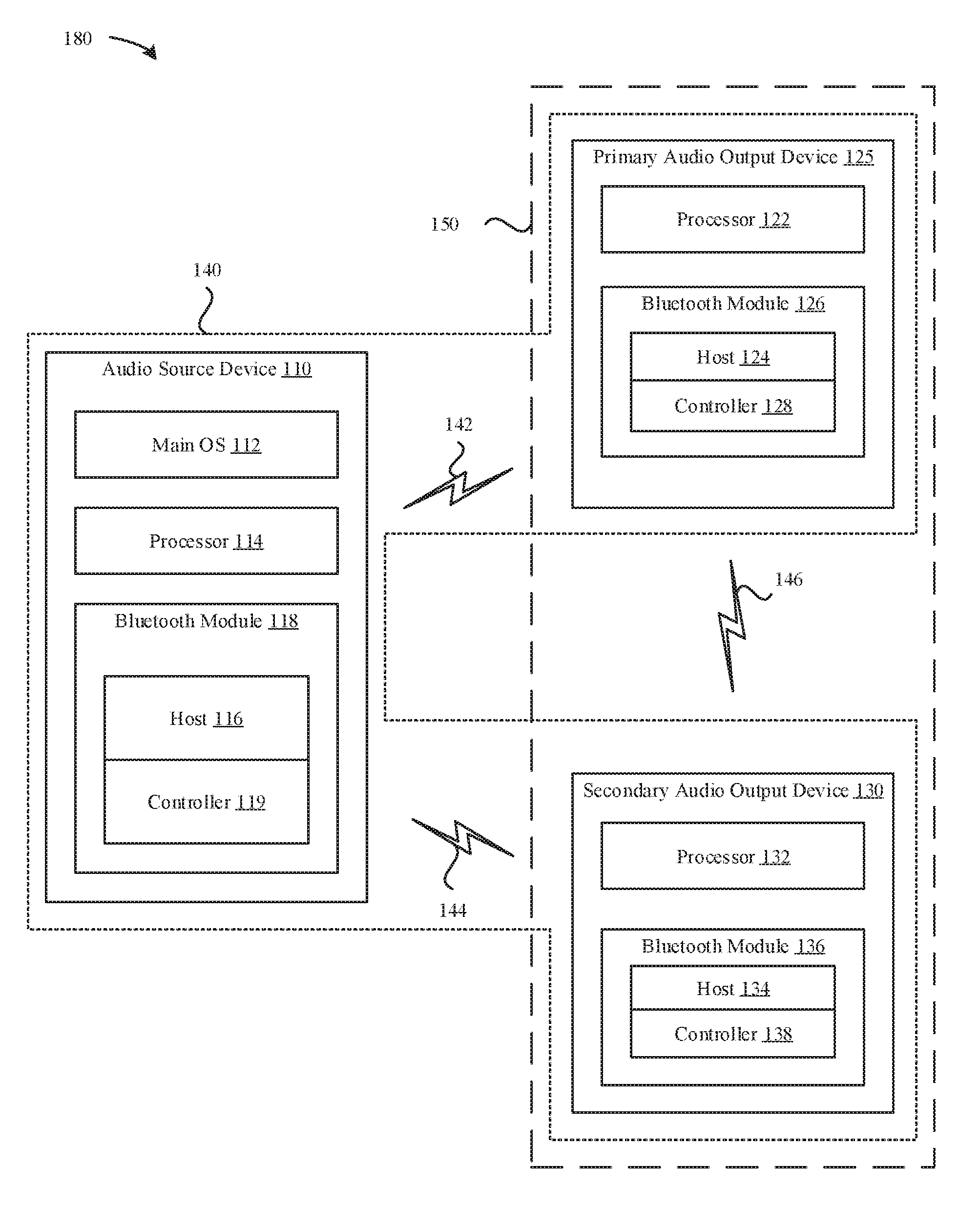
[0047] FIG. 1B illustrates a (simplified) block diagram 180 of several exemplary components of the audio source device 110 and a pair of audio output devices, namely a primary audio output device 125 and a secondary audio output device 130, which can be configured to implement various techniques described herein. The audio source device 110 can provide data, e.g., streaming audio, to both the primary audio output device 125 and the secondary audio output device 130, either separately via parallel wireless connections, or via a connection to the primary audio output device 125, which can relay audio packets and/or control packets to and from the secondary audio output device 130. The primary audio output device 125 and the secondary audio output device 130 can represent a pair of peripheral devices, e.g., a pair of wireless ear buds, which can pair wirelessly with the audio source device 110 and can communicate with each other in addition to communicating with the audio source device 110. In some embodiments, the primary audio output device 125 communicates bi-directionally with the audio source device 110 to exchange control commands on behalf of both the primary audio output device 125 and the secondary audio output device 130. In some embodiments, the primary audio output device 125 and the secondary audio output device 130 can exchange roles as primary and secondary devices respectively. In some embodiments, each of the primary audio output device 125 and the secondary audio output device 130 can receive streaming audio from the audio source device 110, e.g., in parallel. In some embodiments, the primary audio output device 125 and the secondary audio output device 130 can acknowledge none, some, or all streaming audio packets and/or control packets received from the audio source device 110, e.g., separately or jointly providing acknowledgements. In some embodiments, the primary audio output device 125 can acknowledge streaming audio packets and/or control packets received from the audio source device 110 for both the primary audio output device 125 and the secondary audio output device 130.
[0048] As shown in FIG. 1B, the audio source device 110 includes components as described for the audio source device 110 illustrated in FIG. 1A. Similarly, the primary audio output device 125 includes components as described for the audio output device 120 illustrated in FIG. 1A. In addition, the secondary audio output device 130 includes, among other components, a processor 132 and a Bluetooth module 136. The audio source device 110 can communicate with the primary audio output device 125 via a wireless communication link 142 (e.g., over a wireless personal area network (WPAN) link, which can include a Bluetooth link). In some embodiments, the audio source device 110 can also communicate with the secondary audio output device 130 via another wireless communication link 144 (e.g., over a wireless personal area network (WPAN) link, which can include a Bluetooth link). The wireless communication links 142 and 144 can form a WPAN network 140 (or Bluetooth network or piconet) in which the audio source device 110 assumes the role of a master device, and the primary audio output device 125 and the secondary audio output device 130 assume the roles of slave devices. The master device (the audio source device 110) can manage connections with a number of slave devices to form the WPAN (Bluetooth) network 140. Furthermore, the primary audio output device 125 can communicate with the secondary audio output device 130 via a separate wireless communication link 146, e.g., over a second wireless personal area network (WPAN) link, which can include a Bluetooth link or an Untethered Protocol (UTP) link) to form a separate WPAN network 150. With respect to WPAN network 150, the primary audio output device 125 can function as a master device, while the secondary audio output device 130 can function as a slave device. Together the WPAN network 140 and the WPAN network 150 can form a scatternet of two independent WPANs (or piconets).
[0049] In some implementations, Bluetooth modules 118, 126, and 136 include respective hosts 116, 124, 134 that represent upper layers of a BT stack and controllers 119, 128, 138 that can represent lower layers of a BT stack. The hosts 116, 124, 134 can be implemented on the processors 114, 122, 132 respectively and/or on separate processors (not shown). It is also noted that the hosts 116, 124, 134 and the controllers 119, 128, 138 respectively, can represent a single processing unit (e.g., in low power devices) or separate processing units. The upper layers of the BT stack can include the Logical Link Control and Adaptation Protocol (L2CAP), the Attribute Protocol (ATT), the Generic Attribute Profile (GATT), the Security Manager Protocol (SMP) and the Generic Access Profile (GAP), which are components of the different Bluetooth protocols supported by the Bluetooth modules 118, 126, 136. The lower layers of the BT stack and include a Physical Layer (PHY), a Link Layer (LL), and a host controller interface (HCI), which also can be components of the different Bluetooth protocols supported by the Bluetooth modules 118, 126, 136. In some embodiments, hosts 116, 124, 134 communicate with the controllers 119, 128, 138 via the HCI interface. Hosts 116, 124, 134 provide HCI commands to the Link Layer of the respective controllers 119, 128, 138 for the purposes of establishing and/or maintaining BTC connections, while the Link Layers manage advertisement, scanning, and connection establishment.
[0050] The host 116 of the audio source device 110 can communicate with the host 124 of the primary audio output device 125 to establish the communication link 142 to form a part of the WPAN network 140. The host 116 of the audio source device 110 can communicate with the host 134 of the secondary audio output device 130 to establish the communication link 144 to form another part of the WPAN network 140 (alternatively, communication link 144 can be used to snoop (or eavesdrop) on communications between the audio source device 110 and the primary audio output device 125). The host 124 of the primary audio output device 125 can communicate with the host 134 of the secondary audio output device 130 to establish the communication link 146 to form the WPAN network 150. Upon establishment of the communication link 142 with the primary audio output device 125, the host 116 of the audio source device 110 can query the host 124 of the primary audio output device 125 for device capabilities, which can include a topology of the primary audio output device 125. The host 124 of the primary audio output device 125 can respond to the query for capabilities from the host 116 of the audio source device 110 with an indication of scheduling requirements and/or limitations for communication by the primary audio output device 125, e.g., an indication of requirements for internal communication with another device such as for communication with the secondary audio output device 130. In some embodiments, the functions of the host 116 of the Bluetooth module 118 are provided at least in part by the main operating system (OS) 112 executing on the processor 114. In some embodiments, the functions of the host 116 of the Bluetooth module 118 are provided at least in part by firmware executing wireless circuitry of the audio source device 110.
[0051] FIG. 2A illustrates a diagram 200 of an example of ultra-low latency communication between an audio source device 110 and an audio output device 120 over a wireless communication link 102, which can operate in accordance with a WPAN communication protocol, such as a BTC or BTLE (or both) communication protocol or proprietary extensions thereof. The audio source device 110 can send an audio packet 202 via the wireless communication link 102 to the audio output device 120. The audio packet 202 can include encoded audio bytes, which can be derived from uncompressed high rate sampled audio in some embodiments. The audio packet 202 can also optionally include control bytes. In some embodiments, the audio packet 202 includes a payload that includes a combination of 300 bytes of audio data and 50 bytes of control data, where the audio data and/or the control data can be further supplemented with one or more of: (i) forward error correction (FEC) bytes, (ii) a cyclic redundancy check (CRC), or (iii) a message integrity check (MIC). In some embodiments, the audio packet 202 occupies a time period of 550 microseconds, which can be less than half of a 1250 microsecond frame. In some embodiments, each frame of a set of 1250 microsecond frames includes an idle time period that spans at least half of the frame. In some embodiments, the audio packet 202 is formatted in accordance with a BTC wireless communication protocol or an extension thereof, such as a high data throughput format to accommodate at least 300 bytes of audio data per 550 microsecond long audio packet. In some embodiments, twelve audio packets 202 are communicated between the audio source device 110 and the audio output device 120 every 15 milliseconds, with one audio packet transmitted each 1250 microsecond frame. In some embodiments, at least one frame per 15 milliseconds includes a control packet 204 (labeled as an acknowledgement (ACK) packet) communicated in the uplink direction from the audio output device 120 to the audio source device 110. In some embodiments, the control packet 204 is formatted in accordance with a BTLE wireless communication protocol or an extension thereof. The control packet 204 can include one or more of: an acknowledgement for at least one previously received audio packet 202, a block acknowledgement for a set of two or more previously received audio packets 202, a negative acknowledgement for at least one previously received or lost audio packet 202, or control data. The control data of the control packet 204 can include user commands received via an interface of the audio output device 120, e.g., volume adjustment commands. In some embodiments, the control packet 204 occupies a time period of 100 microseconds during the 1250 microsecond frame. In some embodiments, a frame cycle 205 includes a set individual frames 203 with sequential downlink audio packets 202, without uplink control packets 204, followed by a single frame 207 that includes both a downlink audio packet 202 and an uplink control packet 204, and this frame cycle 205 repeats periodically. In some embodiments, the number of frames 203 that only include audio packets 202 can be dynamically adjusted to match performance requirements for end-to-end latency and/or for audio reproduction sound quality. In some embodiments, control information included in some audio packets 202 communicated in the downlink direction from the audio source device 110 to the audio output device 120 include one or more of: interference information, frequency channel use, or frequency channel hopping patterns. In some embodiments, more than one uplink control packet 204 is included in a frame cycle 205. In some embodiments, a frame cycle 205 does not include an uplink control packet 204. The frame cycle 205 shown in FIG. 2A provides for downlink audio data and control data communication from the audio source device 110 to the audio output device 120 with limited (but sufficient) control messaging in the uplink direction from the audio output device 120 to the audio source device 110. Each audio packet 202 in each frame cycle 205 can include a reduced or minimal amount of forward error correction (FEC) encoding, e.g., by using a simple Reed-Solomon code, and the audio output device 120 can correct and/or conceal errors detected in received audio packets 202. Retransmission of audio packets is not provided for in the frame cycle 205 to avoid incurring additional latency in reproduction of the audio at the audio output device 120. Spacing between successive uplink control packets 204 can be determined based on requirements for user-initiated control commands received via the audio output device 120 and transmitted to the audio source device 110. As illustrated in FIG. 2A, the frame 207 includes both a downlink audio packet 202 (labeled A13), which can be formatted based on a BTC protocol, and an uplink control packet 204 (labeled ACK), which can be formatted based on a BTLE protocol. Thus, the scheme illustrated in FIG. 2A provides for mixing a combination of BTC and BTLE packets in the same frame 207.
[0052] FIG. 2B illustrates a diagram 250 of an example of ultra-low latency communication between an audio source device 110 and a pair of wirelessly linked audio output devices, e.g., primary audio output device 125 and secondary audio output device 130. The audio source device 110 communicates with the primary audio output device 125 via the wireless communication link 142, which can operate in accordance with a Bluetooth Classic (BTC) and/or Bluetooth Low Energy (BTLE) wireless communication protocol and/or extensions thereof. In some embodiments, the audio source device 110 communicates bi-directionally over the wireless communication link 142 with the primary audio output device 125, e.g., transmitting audio packets, which can include a combination of audio data and control data, to the primary audio output device 125 and receiving control packets, which can include control information and/or positive/negative acknowledgements from the primary audio output device 125. In some embodiments, the audio source device 110 communicates uni-directionally over the wireless communication link 146 (not shown) with the secondary audio output device 130, e.g., transmitting audio packets, which can include a combination of audio data and control data, to the secondary audio output device 130. In some embodiments, the audio packets are transmitted by the audio source device 110 at the same time to both the primary audio output device 125 and the secondary audio output device 130, e.g., using one transmission, which can be received by both the primary audio output device 125 and the secondary audio output device 130. In some embodiments, the primary audio output device 125 and the secondary audio output device 130 communicate with each other via a separate wireless communication link 146. The audio packet 202 can include a combination of uncompressed high rate sample audio and optionally control bytes, and the control packet 204 can include a combination of one or more of: acknowledgements, control commands, etc. as discussed for FIG. 2A.
[0053] A frame cycle 211 includes a set of frames 203 that include one audio packet 202 per frame 203, where the audio packet 202 includes a combination of audio data and control data, followed by a frame 209 in which the audio packet 202 is followed by a first time period for communication of an inter-device control packet 206 between the primary audio output device 125 and the secondary audio output device 130 and a second time period of communication of a control packet 204 from the primary audio output device 125 to the audio source device 110. The frame cycle 211 can repeat periodically. The frame cycle 211 shown in FIG. 2B provides for downlink audio data and control data communication from the audio source device 110 to the primary and secondary audio output devices 125/130 with limited (but sufficient) control messaging in the uplink direction from the primary audio output device 125 to the audio source device 110 and limited (but sufficient) communication between the primary audio output device 125 and the secondary audio output device 130. As with the scheme illustrated in FIG. 2A, the downlink audio packets 202 can be formatted in accordance with a BTC wireless communication protocol and/or an extension thereof, and the uplink control packets 204 can be formatted in accordance with a BTLE wireless communication protocol and/or an extension thereof.
[0054] FIG. 2C illustrates a diagram 270 of another example of ultra-low latency communication between an audio source device 110 and a pair of wirelessly linked audio output devices, e.g., the primary audio output device 125 and the secondary audio output device 130. FIG. 2C extends the schemes illustrated in FIGS. 2A and 2B to include a gap time period 208 during each frame cycle 213 to provide for at least one retransmission. Each frame cycle 213 includes a set of frames 203 that include downlink audio packets 202 (from the audio source device 110 to the primary audio output device 125 and the secondary audio output device 130), without uplink control packets (from the primary audio output device 125 or the secondary audio output device 130 to the audio source device 110) or communication of a control packet between the primary and secondary audio output devices 125/130, followed by a single frame 209 that includes an uplink control packet 204 communicated from the primary audio output device 125 to the audio source device 110 and a inter-device control packet 206 communicated between the primary audio output device 125 and the secondary audio output device 130. The inter-device control packet 206 can include user-initiated control commands, such as to change a volume level or another audio playback function. The frame cycle 213 of FIG. 2C differs from the frame cycle 211 of FIG. 2B by including a gap time period 208. More generally, the frame cycle 213 schedules fewer downlink audio packets 202 for each cycle to allow for one (or for longer gaps more than one) retransmission of a previously sent but erroneously received (or lost) downlink audio packet 202. Comparing the frame cycle 211 in FIG. 2B with the frame cycle 213 in FIG. 2C, the former includes thirteen scheduled downlink audio packets 202, while the latter only includes twelve scheduled downlink audio packets 202, which allows for a single retransmission. In some embodiments, when the primary audio output device 125 detects an unrecoverable error for or a loss of an audio packet 202, the primary audio output device 125 opportunistically sends an uplink control packet (not shown) to the audio source device 110 to indicate the error and/or loss of the audio packet 202 and thereby requests retransmission of the indicated errant or lost audio packet 202. In some embodiments, the uplink control packet includes a negative acknowledgement transmitted to the audio source device 110 by the primary audio output device 125 in the same frame 203 in which the errant/lost audio packet 202 occurs. By responding in the same frame 203, the audio source device 110 can retransmit the errant/lost audio packet 202 in an immediately subsequent frame 203 and shift the remaining audio packets 202 to frames 203 that follow thereafter. Thus, the gap time period 208 can be placed as required within the frame cycle 213 to accommodate a loss of an audio packet 202. The number of gap time periods 208 can be changed, e.g., increased to accommodate more retransmissions per frame cycle 213, or decreased, e.g., not used when no retransmissions are required. As retransmission of audio packets 202 incur latency, an upper threshold on the number of retransmissions per frame cycle 213 can limit additional incurred latency. When the upper threshold number of retransmissions per frame cycle 213 is reached during a particular frame cycle 213, no additional retransmission may occur until the next frame cycle 213. Retransmissions of an audio packet 202 for a particular frame 203, in some embodiments, only occur in an immediately subsequent frame 203 to reduce latency. In some embodiments, the primary audio output device 125 and/or the secondary audio output device 130 can also perform packet loss concealment in lieu of and/or in addition to requesting retransmission of an errant/lost audio packet 202.
[0055] FIG. 3A illustrates a diagram 300 of an exemplary format for a forward audio packet that can be used for communicating audio data from the audio source device 110 to the audio output device 120 and/or to a set of paired audio output devices, such as to the primary audio output device 125 and the secondary audio output device 130 in accordance with the ultra-low latency audio (ULLA) communication protocol described herein. The forward audio packet can use a variant of BT Classic packet, e.g., a high data rate (HDR) BT packet (or a variant thereof) and can include audio information as well as control information. BT HDR packets can be considered a proprietary extension of standard BT Classic EDR packets that increases the wireless radio frequency (air) rate from the standard 2 or 3 Mbps of BT Classic EDR data rates to 4 or 8 Mbps for BT HDR packets by shortening the EDR2 symbol time, e.g., reducing the symbol time to one-half or one-quarter the standard symbol time. While standard BT EDR2 packets are transmitted at a rate of 1 Msps (symbols per second) using 2 bits per symbol QPSK modulation, the BT HDR packets are transmitted at a rate of 2 Msps (for HDR4 data rates of 4 Mbps) or at a rate of 4 Msps (for HDR 8 data rates of 8 Mbps) using 2 bits per symbol QPSK modulation. As shortening the symbol time reduces radio frequency link margins for a given transmission energy, forward error correction (FEC) encoding, such as Reed-Solomon (RS) encoding, can be added to the BT HDR packets to increase the RF link margin, e.g., by 3 dB, at the expense of some bit redundancy that reduces the audio payload data rate (before RS encoding). ULLA audio packets, in some embodiments, can be formatted as BT HDR8 packets. The forward audio packet begins with an access code field 302 that includes a fixed zero-one pattern of eight symbols followed by a 40-bit long access code, where the access code field 302 is encoded using GFSK at 1M samples per second (1 Msps), which is equal to 1M bits per second using 1 bit per sample encoding. The access code field 302 spans 48 micro-seconds (.mu.s), which is shorter than the 72 .mu.s used for a regular BT HDR packet. The access code field 302 is followed by a guard interval field 304 spanning 2 .mu.s, which is shorter than the 5 .mu.s of the regular BT HDR packet. After the guard interval field 304, a synchronization (sync) field 306 spans a length of 33 .mu.s, which is longer than the 30 .mu.s of a regular BT HDR packet to provide for increased SNR. The sync field 306 is followed by a variable length ULLA payload field 308 that is formatted using eight-symbol differential phase shift keying (8DPSK), as is also used for a regular BT HDR packet and contains the ULLA audio data (and optionally control and/or application data). The forward audio packet concludes with a trailer 310 that spans two symbols in length.
[0056] FIGS. 3B and 3C illustrate different formats for the ULLA payload field 308 of the forward audio packet of FIG. 3A. FIG. 3B illustrates a diagram 320 of an ULLA payload field 308 that includes audio without control or application data and a diagram 330 for an ULLA payload field 308 that includes both audio and control/application data. Both ULLA payload fields 308 begin with a 40-bit ULLA header 322 and include a 32-bit message integrity check (MIC) field 324, a variable length audio field 326 that can include up to 300 bytes, and end with a 32-bit cyclic redundancy check (CRC) 328. In some embodiments, the ULLA header field 322 is authenticated using the MIC field 324, while the audio field 326 is encrypted but not authenticated. FIG. 3B further illustrates a diagram 330 of an ULLA payload field 308 that includes audio with additional control and/or application level data in a variable length control/app data field 332. The control data can include link management protocol (LMP) data and the application level data can be used by one or more applications in conjunction with the audio data included in the audio field 326. When included, control/application data precedes audio data in the ULLA payload field 308 and is encrypted as well as authenticated using the MIC field 324. As further illustrated by diagram 340 of FIG. 3C, an ULLA payload field 308 can include an audio retransmission field 342 that is protected by its own accompanying interim CRC field 344, where retransmitted audio data precedes new audio data included in the subsequent audio field 326 followed by another CRC field 328. Both the new audio data in the audio field 326 and the retransmitted audio data in the audio retransmission field 342 are protected by CRCs to increase packet robustness. Audio data, however is not authenticated. Optional control/application data, when included in the control/app data field 332 is both encrypted an authenticated, while the ULLA header 322 is always authenticated. In some embodiments, as illustrated by diagram 350, an ULLA payload field 308 can be further protected by an optional low-density parity-check (LDPC) code in an appended parity field 352 that can span up to 350 bytes.
[0057] FIG. 3D illustrates a diagram 360 of a format for the ULLA header field 322 of the ULLA payload field 308 of a forward audio packet. The ULLA header field 322 begins with a one-bit length audio type 362 that can indicate whether the ULLA payload 308 includes a retransmission of previously communicated audio along with new audio or only new audio. A 12-bit audio length field 364 indicates a length of the ULLA audio field 326. If the ULLA payload 308 includes a retransmission, then the length indicated in the audio length field 364 applies separately to the ULLA audio field 326 and the audio retransmission field 342, i.e., both audio fields have the same length. A two-bit long audio sequence field 366 is initially set to a zero value for the first audio packet and increments for each newly sent audio packet. In some embodiments, the audio sequence field 366 does not increment for an ULLA payload 308 that includes both new audio and retransmitted audio. An eight-bit long control length 368 indicates a length of the optional control/app data field 332 when included and otherwise the control length 368 includes a value of zero. A three-bit control LLID field 370 can be used for higher layer protocol multiplexing and packet type identification as detailed in table 382 of FIG. 3D. The control LLID field 370 can indicate the start and continuation of an RLMP packet that is routed between audio output (sink) devices 125, 130, the start and continuation of L2CAP packets, or the start and continuation of LMP packets based on particular values in the control LLID field 370. A one-bit control sequence field 372 is initialized to a zero value and incremented for each new control packet sent. When the ULLA payload 308 does not include control/application data, e.g., as indicated by the control length field 368 having a zero value, the control sequence field value is disregarded. A two-bit control destination field 374 specifies a destination for the control/application data included in the ULLA payload 308 as detailed in table 384. Control/application data can be sent to either the primary audio output device 125, the secondary audio output device 130, or to both the primary and secondary audio output devices 125, 130, and indicated as such in the control destination field 374. Two one-bit acknowledge (ACK) fields, R-ACK field 376 and L-ACK field 378, can indicate to the primary and/or secondary audio output devices 125, 130 that the source device 110 received reply packets communicated from the primary and/or secondary audio output devices 125, 130, where one of the ACK fields corresponds to the primary audio output device 125 and the other ACK field corresponds to the secondary audio output device 130. A one-bit LDPC field 380 of the 40-bit ULLA header field 322 indicates whether an optional LDPC field is appended at the end of the ULLA payload 308 (as shown in FIG. 3C). The ULLA header field 322 concludes with an 8-bit reserved for future use (RFU) field 381.
[0058] FIG. 3E illustrates a diagram 390 of error protection for different portions of an ULLA payload 308. The ULLA header 322 and the optional control/application data 332 can be authenticated by the MIC field 324. Additionally, the control/application data 332 is encrypted. The audio retransmission field 342 is encrypted but not authenticated and is further error protected by an interim CRC field 344. The audio field 326 is encrypted but also not authenticated and is error protected by the CRC field 328. In some embodiments, the ULLA payload 308 includes an optional LDPC parity field 352 that is not additionally protected by another error correction code, message integrity check, or cyclic redundancy check field.
[0059] FIG. 4 illustrates a diagram 400 of an exemplary format for a reverse acknowledgement packet that can be used for communicating acknowledgements and/or negative acknowledgements from the audio output device 120 and/or from a set of paired audio output devices, such as the primary audio output device 125 and the secondary audio output device 130 to the audio source device 110 in accordance with the ultra-low latency audio (ULLA) communication protocol described herein. Reverse acknowledgement packets can indicate whether the audio output device(s) 120, 125 correctly received the forward audio packets sent by the audio source device 110. The reverse acknowledgement packet can use a Bluetooth Low Energy (BTLE) 2M bit per second (2 Mbps) Gaussian Minimum Shift Keying (GMSK) modulation with an 8 .mu.s preamble and a 16 .mu.s access code, which corresponds to a 16-bit preamble and a 32-bit access code at a 2 Msps (symbols per second) transmission rate. The 32-bit access code field 402 begins the reverse acknowledgment packet followed by a 16-bit header field 404, an 8-bit HEC field 406, a variable length reverse acknowledgment payload 408, and ending with a 32-bit MIC field 420 that protects the reverse acknowledgment payload 408, which is also encrypted. The three-bit LLID field 412 of the header field 404 can be used for higher layer protocol multiplexing and packet type identification as detailed in table 430 of FIG. 4. The LLID field 412 can indicate the start and continuation of an UTP packet that is routed between audio output (sink) devices 125, 130, the start and continuation of L2CAP packets, or the start and continuation of LMP/Control packets based on particular values in the control LLID field 412. The ACK field 414 of the header field 404 can indicate to the audio source device 110 positive acknowledgment of reception of a source ULLA packet (forward audio packet) by the respective audio output device 120, 125, 130. A one-bit sequence number (SEQ) field 416 indicates a packet sequence number and is followed by a three-bit reserved for future use (RFU) field 418 and concludes with an eight-bit length (LEN) field that indicates the length of the packet in bytes. Each of the ACK field 414, the SEQ field 416, and the LEN field 420 can be formatted in accordance with a BTLE specification. The reverse acknowledgment packet is encrypted and concludes with the MIC field 410, which can be used also as a CRC in that detection of a MIC failure at the audio source device 110 can result in a negative acknowledgment (NAK) of the reverse acknowledgment packet to the corresponding audio output device 120, 125, 130.
[0060] FIG. 5A illustrates a diagram 500 of an example of bit stream processing for a forward audio packet that can be performed by the audio source device 110. At 502, audio and control data, e.g., audio field 326 and optional control/application data field 332, are encrypted using an Advanced Encryption Standard (AES) symmetric encryption algorithm, and the message integrity check (MIC) 324 is generated. The ULLA header 322 is not encrypted but is included when generating the MIC 324 using AES authentication. An audio retransmission field 342, when included, can have been AES encrypted for a previously transmitted forward audio packet. At 504, the 32-bit CRC field 328 is generated for the audio field 326. The audio retransmission field 342, when included, is followed by its own 32-bit interim CRC field 344. At 506, BT HDR Reed-Solomon (RS) encoding, e.g., a RS(64,60) encoder, is applied to the forward audio packet before whitening at 508. The ULLA payload header 322 is also protected using the same RS(64,60) encoder using its own (partial) RS block, in some embodiments. Byte interleaving is not applied for the forward audio packet to reduce latency. At 510, an optional set of Low Density Parity Check (LDPC) parity bits (i.e., optional parity field 352) are calculated and appended to complete the ULLA payload. At 512, the forward audio packet is transmitted via a radio frequency (RF) interface by the audio source device 110 to the audio output device(s) 120, 125, 130. At the receiving audio output device(s) 120, 125, 130, at 514 de-whitening is applied followed by RS decoding at 516 and a CRC check at 518. At 520, AES decryption and MIC validation is performed. If the optional LDPC parity bits were included, and when the CRC check at 518 indicates a CRC failure, the received samples from the RF interface 512, which can be recorded at 522, can be processed at 524 by an LDPC decoder to produce a corrected set of received audio data, which can be reprocessed by the standard receiver decoding chain of blocks, i.e., via de-whitening at 514, RS decoding at 516, CRC check at 518, and AES decryption and MIC validation at 520. The forward audio packet bit stream processing illustrated in FIG. 5A differs from standard BT processing at least in that (i) the ULLA payload header 322 is protected using the same RS(60, 64) code using its own partial (RS) block, (ii) byte interleaving is not used, and (iii) optional LDPC parity (with re-processing at the receiver) is included.
[0061] Bit stream processing for ULLA reverse acknowledgement packets can be performed in accordance with a BTLE specification as defined for data packets. In some embodiments, a MIC 410 is always applied to ULLA reverse acknowledgement packets. CRC generation for ULLA forward audio packets can be in accordance with a BT Classic specification or extension thereof, e.g., BT HDR, while CRC generation for ULLA reverse acknowledgement packets can be in accordance with a BTLE specification. In some embodiments, an initial value for BTLE CRC can be communicated by the audio source device 110 to the audio output devices 120, 125, 130 when establishing the ULLA process. Whitening for ULLA forward audio packets can be in accordance with a BT Classic specification or extension, e.g., as defined for BT HDR data packets, while whitening for ULLA reverse acknowledgment packets can be in accordance with BTLE specification as defined for BTLE data packets. In some embodiments, the GFSK baseband header of an ULLA forward audio packet, e.g., the access code field 302 shown in FIG. 3A, is protected with parity bits using a Forward Error Correction (FEC) code, e.g., a 1/3 code, in accordance with a BT specification.
[0062] FIG. 5B illustrates a diagram 530 of optional LDPC processing for an ULLA forward audio packet to add extra protection using an LDPC encoder. In some embodiments, ULLA forward audio packets without retransmissions include LDPC parity, and ULLA forward audio packets with retransmissions do not include LDPC parity. LDPC protection can be applied to the complete ULLA payload section of the ULLA forward audio packet including the Reed-Solomon (RS) encoded bytes. The exemplary ULLA forward audio packet shown in FIG. 5B includes an 8-byte ULLA header 532, a 12-byte ULLA control 534, a 4-byte MIC 536, a 300-byte ULLA audio payload 538, and a 4-byte CRC 540, which totals to a payload with RS coding 544 of 350 bytes. The LDPC parity 542 includes 350 bytes, which are divided into individual 50-byte blocks indicated as block1 542-1 to block1 542-7. The first block, block1 542-1, protects the start of the ULLA payload, i.e., the ULLA header 532, while the last block, block1 542-7, protects the end of the ULLA payload, i.e., up to the last bit of the CRC 540, with the intervening blocks protecting the intervening bits. In case the audio payload size does not align with an LDPC block size used, padding bits can be added.
[0063] FIG. 6 illustrates a diagram 600 of audio sequence numbering for ULLA forward audio packets. ULLA audio packets are flushable, and therefore new audio packet payloads may be transmitted regardless of reverse acknowledgments received. Audio sequence numbering indicates sequence numbers for audio portions with a baseband packet, which can contain multiple audio portions in some embodiments. A sequence number is applied to each forward audio packet, and sequence numbers increments for each audio packet that includes a new portion as illustrated in FIG. 6.
[0064] ULLA control payload sequence numbering can be in accordance with a BT Classic specification, except reverse acknowledgment packets from both a primary audio output device 125 and a secondary audio output device 130 (when two untethered audio output devices are used) are considered for retransmission decisions. Sequence numbering for ULLA packets can inherit a last acknowledged (ACK) sequence number value used on a connection before entering the ULLA transmission mode. For an existing ULLA transmission mode, an ACL sequence numbering value can inherit a last control sequence numbering used on the ULLA connection. In some embodiments, ULLA control payloads are not flushed (in contrast with ULLA audio payloads). The audio source device 110 continues to retransmit a control payload portion until positive acknowledgment is received from the audio output devices 120, 125, 130. As illustrated by the ULLA header format diagram 360 in FIG. 3D, acknowledgment bits, R-ACK 376 and L-ACK 378, can provide one-bit indications of reception of valid reverse acknowledgment packets from the primary audio output device 125 and the secondary audio output device 130, e.g., untethered, wirelessly connected audio ear buds servicing right and left channels. For a single audio output device 120, e.g., a tethered audio output device with a wired connection between left and right channels, only the R-ACK 376 bit is used. In some embodiments, all reverse acknowledgement packets received by the audio source device 110 are acknowledged, including empty packets. As illustrated by the diagram 400 of FIG. 4, reverse acknowledgment packets include a one-bit ACK 414 and a one-bit sequence number (SEQ) 416. The SEQ 416 bit is set to a "one" value for the initial reverse acknowledgment packet sent and advanced (flipped in value) after the audio source device 110 acknowledges valid reception of the reverse acknowledgment packet, e.g., by setting its own acknowledge bit (R-ACK 376 or L-ACK 378) depending on from which audio output device 120, 125, 130 the reverse acknowledgment packet was received. The value of the SEQ 416 bit is flipped for each acknowledgement received from the audio source device 110, including both forward audio packets with audio payloads and empty packets. Reverse acknowledgment packets are not flushed and retransmitted by the corresponding audio output device 120, 125, 130 until acknowledged by the audio source device 110.
[0065] FIG. 7 illustrates a diagram 700 of a 1.25 ms BT frame that includes an initial inter-frame spacing (IFS), an ULLA forward audio packet 702 from an audio source device 110, a second IFS and a reverse acknowledgment (ACK) 704 from an audio output device 120. The ULLA forward audio packet 702 is formatted as a non-standard BT HDR packet as described herein, and the reverse ACK 704 from is formatted as a standard BTLE 2 Mbps packet as also described herein. FIG. 7 also illustrates a diagram 710 of a 1.25 ms BT frame that includes an initial IFS, an ULLA forward audio packet 702 from an audio source device 110, a second IFS, a reverse ACK 704-1 from a primary audio output device 125, a reverse ACK turnaround (RAT) time period, and a reverse ACK 704-2 from a secondary audio output device 130. Reverse acknowledgements can be sent back to the audio source device separated from the forward audio packet 702 by the IFS. As forward audio packets 702 can vary in length, the start time for reverse ACKs can also vary. The time period after the IFS after the forward audio packet 702 to the end of the BT frame, during which reverse ACKs can be sent, can be designated as a response period. When both a primary audio output device 125 and a secondary audio output device 130 are used and send reverse ACKs, the response period can be equally divided into two time periods for their responses separated by the RAT time period in between. The first time period for response can be used by the primary audio output device 125, while the second time period for response can be sued by the secondary audio output device 130. In some embodiments, the second time period for response used by the secondary audio output device 130 does not depend on the length of the reverse ACK used by the primary audio output device, e.g., the spacing between the primary reverse ACK 704-1 and the secondary reverse ACK 704-2 is at least as long as a minimum length RAT time period but can be longer when the primary reverse ACK 704-1 does not occupy all the time allotted for the primary reverse ACK 704-1. The size of the primary reverse ACK 704-1 and the secondary reverse ACK 704-2 need not be identical. Untethered (wireless connected) audio output devices can each send reverse ACKs, while a tethered (wire connected) audio output device can send only one reverse ACK. In some embodiments, the IFS is 130 .mu.s in length, the RAT is at least 32 .mu.s in length, the forward audio packet 702 is between 107 .mu.s in length (empty packet) and 886 .mu.s in length, and the reverse ACKs 704 are between 32 .mu.s and 420 .mu.s in length. In all cases, the forward audio packet 702 and reverse ACKs 704 fit within a single BT frame of 1250 .mu.s in length.
[0066] FIG. 8 illustrates a diagram 800 of an optional ULLA sniff mode to reduce wireless transmission times (providing quiet periods for each cycle) compared with a default ULLA active mode in which an ULLA packet is sent in every BT frame to ensure a maximal throughput of 1.92 Mbps audio transmission from the audio source device 110 to the audio output devices 120, 125, 130. The ULLA sniff mode provides a lower radio frequency (air) duty cycle at the expense of reduced maximum data throughput. In the ULLA sniff mode, the audio source device 110 and the audio output device(s) 120, 125, 130 agree on periodic anchor points at which they communicate and exchange information. A time interval between anchor points is set to meet a preferred data throughput. For each anchor point, a pre-determined number of retransmission attempts is permitted. When the number of retransmission attempts for a given anchor point is reached, the audio source device 110 flushes any remaining audio data queued for retransmission and suppresses further transmissions to the audio output devices 120, 125, 130 until the next anchor point. As described herein, control payloads are not flushable, and thus control data will be retransmitted (and not flushed) at the next anchor points as required and can be carried across multiple anchor points until successful acknowledgment is received. In FIG. 8, in a first BT frame, the audio source device 110 transmits, to the primary audio output device 125 and the secondary audio output device 130, a first forward audio packet 804-1 with an audio sequence number value of one and a control sequence number value of one. The primary audio output device 125 sends a reverse ACK that indicates a negative acknowledgement (NAK) indicated by the "N" in FIG. 8, while the secondary audio output device 130 sends a reverse ACK with a positive acknowledgment (ACK) indicated by the "A" in FIG. 8. In a second, subsequent BT frame, the audio source device 110 resends the previous audio data and new audio data as the forward audio packet 804-2, with the audio and control sequence numbers repeated (as the previously sent data was not positively acknowledged by both of the audio output devices). Again, the primary audio output device 125 sends a NAK, while the secondary audio output device 130 sends an ACK. For the example shown in FIG. 8, the sniff interval spans four BT frames with two BT frames designated as quiet periods (not transmission in either direction) and two BT frames for bi-directional communication between the audio source device 110 and the audio output devices 125, 130. As the maximum number of transmission attempts for the audio data is reached for the sniff interval, the audio data is flushed, while the control data transfers over for retransmission to the next sniff interval. In the first BT frame of the subsequent sniff interval, new audio is sent with an audio sequence number value of three and a retransmission of control data is sent with a control sequence number value of one. Both the primary and secondary audio output devices 125, 130 respond in this BT frame with positive ACKs.
[0067] FIG. 9A illustrates a diagram 900 of a mapping of data for logical channels to physical channels for an ULLA wireless protocol. The audio source device 110 communicates ULLA audio packets and application data to the primary audio output device 125 and the secondary audio output device 130 via the forward audio physical channel 902. Additionally, the audio source device 110 sends link management (control data) to the primary audio output device 125. The primary audio output device 125 and the secondary audio output device 130 provide their own application data and remote link management protocol (RLMP) data via the reverse acknowledge physical channel 904. Additionally, the primary audio output device 125 sends link management (control data) to the audio source device 110 via the reverse acknowledge physical channel 904. In some embodiments, the primary audio output device 125 and the secondary audio output device 130 communicate with each other via a primary/secondary physical channel 906, over which RLMP data can be exchanged. In some embodiments, RLMP data between the primary audio output device 125 and the secondary audio output device 130 is communicated via the audio source device 110, which can relay the RLMP data. Forward audio packets can include combinations of audio data, application data, and link management control data as described herein.
[0068] FIG. 9B illustrates a diagram 950 of audio channel synchronization for an ULLA wireless protocol. An audio source 952 of the audio source device 110 produces digital audio samples, e.g., two channels of audio samples corresponding to left and right stereo audio, to the Bluetooth module 118 for transmission via the ULLA wireless protocol to the primary audio output device 125 and the secondary audio output device 130. The audio source device 110 also outputs an audio sampling clock, e.g., at 48 kHz, that is synchronous with the digital audio samples. The Bluetooth module 118 can divide down the audio sampling clock, e.g., by a factor of six, to derive a clock to use for the ULLA wireless protocol transmissions over the wireless communication links 142/144 to the primary and secondary audio output devices 125/130. In some embodiments, the wireless communication transmission of the audio between the audio source device 110 and the primary and secondary audio output devices 125/130 can be a multicast transmission at a rate of 800 packets per second. The ULLA wireless protocol transmissions can facilitate a synchronous pulse code modulation (PCM) based transmission scheme where the ULLA BT packets are synchronized to the 48 kHz audio sample clock. The transmit clock of the Bluetooth module 118 can be derived from the 48 kHz audio sample clock. The Bluetooth modules 126/136 of the primary and secondary audio output devices 125/130 can extract a timing signal from the packets received. For example, the Bluetooth modules 126/136 can derive an 800 Hz clock from the 800 packets per second multicast transmission received from the audio source device 110 and can feed this derived 800 Hz clock to phase lock loops (PLLs) 954/958 of the primary and secondary audio output devices 125/130. Each of the PLLs 954/958 can upscale the 800 Hz clock by a factor of 60 to produce a derived 48 kHz clock that can feed respective digital-to-analog converters (DACs) 956/960 of the primary and secondary audio output devices 125/130 to reproduce the audio channels, which are output as audio 962 from DAC 956 of the primary audio output device 125 and audio 964 from DAC 969 of the secondary audio output device 130. As both of the primary and secondary audio output devices 125/130 are synchronized to the audio source device 110 via Bluetooth clock synchronization, by also linking the Bluetooth transmission and reception clocks to the audio sampling clocks, the audio samples derived at the primary and secondary audio output devices 125/130 are also synchronized to the original audio samples and to each other. Two channel audio synchronization at the primary and secondary audio output devices 125/130 with proper time and phase alignment for the output audio is achieved by this derived clock mechanism.
[0069] In some embodiments, the primary audio output device 125 provides a synchronization packet to the secondary audio output device 130, e.g., every 25 ms, to maintain audio channel synchronization for audio streaming, including when using a Bluetooth A2DP profile for music streaming. In some embodiments, when using a Bluetooth HFP profile for real-time voice communication, clocks are derived by one or both of the primary and secondary audio output devices 125/130 from the audio stream.
[0070] FIG. 10A illustrates a diagram 1000 of an example of encapsulation of link management protocol (LMP) data bytes in ULLA forward audio packets. An LMP packet having a total of twenty-seven bytes is divided into three separate ULLA forward audio packets as control payloads of ten, ten, and seven bytes each. The ULLA header of each ULLA packet can indicate the number of control bytes included in the ULLA packet and whether the control bytes are the initial bytes of the LMP packet (first=1) or subsequent bytes (first=0). During ULLA active transmission mode, LMP, remote LMP (RLMP), and application data traffic can be encapsulated into control payloads of ULLA forward audio packets.
[0071] FIG. 10B illustrates a diagram 1050 of an example of encapsulation of LMP data bytes in reverse acknowledgement packets. An LMP packet having a total of twenty-seven bytes is divided into three separate ULLA reverse acknowledgment packets as control payloads of ten, ten, and seven bytes each. The header of each reverse acknowledgment packet can indicate the number of control bytes included in the ULLA packet and whether the control bytes are the initial bytes of the LMP packet (LLID=100) or subsequent bytes (LLID=101). During ULLA active transmission mode, LMP, remote LMP (RLMP), and application data traffic can be encapsulated into control payloads of ULLA reverse acknowledgment packets.
[0072] FIG. 11A illustrates a diagram 1100 of an exemplary ULLA link management protocol message exchange sequence to indicate support for a ULLA transmission mode. In some embodiments, the ULLA link management protocol is defined based on additions to a BT HDR link management protocol. A first device, e.g., an audio source device 110, can indicate support to a second device, e.g., an audio output device 120, 125, 130, by exchanging a set of LMP messages when the two devices connect to each other. After establishing a connection over which LMP messages can be exchanged, the first device, LM-A, inquires of the second device, LM-B, of one or more LMP versions supported by the second device by sending an LMP Version Request message. The second device, LM-B, responds with an indication of LMP versions supported using an LMP Version Response message. In some embodiments, the LMP Version Request and LMP Version Response messages are formatted in accordance with a BT HDR LMP message with additional proprietary bits (using reserved bits or extra bits as required). Additionally, the first and second devices, LM-A and LM-B, can determine whether a particular manufacturer, indicated as "Manufacturer X", identifier (ID) is detected where LM-A recognizes that LM-B may be manufactured by the same company, e.g., each of LM-A and LM-B are identified by an identical particular company ID, such as "Apple". When the particular manufacturer ID is positively detected, the first device LM-A can inquire of the second device LM-B whether one or more LMP proprietary features are supported by sending an LMP Proprietary Feature Request message. The second device LM-B can reply with an LMP Proprietary Feature Response message that indicates LMP proprietary features supported. Furthermore, the first and second devices, LM-A and LM-B, can determine whether a high data rate (HDR) BT mode is supported, and the first device LM-A can send an LMP HDR Version Request message to the second device LM-B to learn HDR modes supported, and the second device LM-B can respond with an LMP HDR Version Response indicating one or more HDR versions supported.
[0073] FIG. 11B illustrates a diagram 1120 of an exemplary LMP message sequence to transition an audio source device 110 that is paired with an audio output device 120 into an ULLA active mode. The audio output device 120 can be connected to an additional audio output device via a tethered (wired) connection, in some embodiments. Initially, the audio source device 110 and the audio output device 120 can each be in an idle sniff mode listening for LMP messages. The audio source device 110 can send an Unsniff Request LMP message to the audio output device 120, which can response with an LMP Accepted Response message indicating an agreement to change modes. The audio source device 110 can pause any Asynchronous Control Link (ACL) traffic and subsequently send an ULLA Request LMP message to the audio output device 120 to indicate a request to switch to the ULLA mode. The audio output device 120 can synchronize with an additional audio output device, such as where the audio output device 120 outputs a first stereo channel of audio and the additional audio output device outputs a second stereo channel of audio. The audio output device 120 can also changes its operating mode to an ULLA mode and indicate the mode change to the additional audio output device to cause the additional audio output device to also change modes. The audio output device 120 can also pause any ACL traffic. Subsequently, the audio output device can indicate acceptance of the ULLA request to switch to ULLA mode by sending an Accepted Extension Response LMP message to the audio source device 110. The audio source device 110 can then indicate a particular transition time at which the audio source device 110 and audio output device 120 should transition into the ULLA mode by sending an ULLA Enter (Transition Time) LMP message to the audio output device 120. Subsequently, at the transition time indicated previously, the audio source device 110 and the audio output device 120 enter the ULLA mode, and begin communication using the ULLA mode.
[0074] FIG. 11C illustrates a diagram 1140 of an exemplary LMP message sequence to transition an audio source device 110 that is paired with a primary audio output device 125 and a secondary audio output device 130 to an ULLA mode. The primary audio output device 125 can be connected to the secondary audio output device 130 via an untethered (wireless) connection in some embodiments. Initially, the primary audio output device 125 and the secondary audio output device 130 can be connected to each other in an Untethered Protocol (UTP) sniff mode. The audio source device 110 can initiate the transition to the ULLA mode by sending an ULLA Request LMP message to the primary audio output device 125. The primary audio output device 125 can send an Unsniff Request LMP message to the secondary audio output device 130 to exit the UTP sniff mode, to which the secondary audio output device 130 can send an Accepted Response LMP message to indicate acceptance of the request to exit UTP sniff mode. The secondary output device 130 can enter a snoop mode to listen for messages from the audio source device 110 to determine a transition time for entering the ULLA mode. The primary audio device can send a Disconnect UTP LMP message to the secondary audio output device 130, which can respond with an Accepted Response LMP message, after which the primary audio output device 125 and the secondary audio output device 130 can disconnect the UTP connection between each other and enter an active snoop mode to listen for LMP messages from the audio source device 110. After the UTP connection is disconnected, the primary audio output device 125 can indicate to the audio source device acceptance of the ULLA request LMP message to enter the ULLA mode by sending an Accepted Extension Response LMP message. The audio source device 110 can then indicate a particular transition time at which the audio source device 110, the primary audio output device 125, and the secondary audio output device 130 should transition into the ULLA mode by sending an ULLA Enter (Transition Time) LMP message to the primary audio output device 125. The primary audio output device 125 can directly receive the ULLA Enter (Transition Time) LMP message to obtain the ULLA mode transition time, while the secondary audio output device 130 obtain the same transition time by snooping to receive the ULLA Enter (Transition Time) LMP message sent to the primary audio output device 125. The primary audio output device can indicate acceptance of the ULLA Enter (Transition Time) LMP message to the audio source device 110 by sending a baseband ACK via the LMP. Subsequently, at the transition time indicated previously, the audio source device 110, the primary audio output device 125, and the secondary audio output device 130 enter the ULLA mode. The audio source device 110 can send ULLA Mode Active messages to both the primary audio output device 125 and the secondary audio output device 130 to indicate that communication using the ULLA mode is now active.
Representative Embodiments
[0075] In some embodiments, a method for low latency communication between an audio source device and a primary audio output device includes the audio source device performing actions that include: (i) sending, to the primary audio output device during a first portion of a frame, a forward audio packet that includes audio data and is formatted in accordance with a Bluetooth (BT) Classic wireless communication protocol or a high data rate (HDR) extension thereof; (ii) receiving, from the primary audio output device during a second portion of the frame, a first reverse acknowledgement (ACK) packet that indicates a request for retransmission of the audio data and is formatted in accordance with a Bluetooth Low Energy (BTLE) wireless communication protocol or an extension thereof; (iii) sending, to the primary audio output device, a second forward audio packet in a first portion of a subsequent frame that immediately follows the frame, the second forward audio packet including retransmission of the audio data; and (iv) disallowing retransmission of audio data for all subsequent frames of a frame cycle that includes the frame and the subsequent frame.
[0076] In some embodiments, the method further includes the audio source device receiving, during a final frame of the frame cycle from the primary audio output device, a second reverse ACK packet that includes information derived from inter-device control packets received by the primary audio output device from a secondary audio output device that is connected to the primary audio output device. In some embodiments, the primary audio output device and the secondary audio output device are connected to each other wirelessly; and the second reverse ACK packet further includes a block acknowledgement for a set of two or more forward audio packets. In some embodiments, the second reverse ACK packet further includes control data from the primary audio output device or the secondary audio output device. In some embodiments, the method further includes the audio source device receiving during the second portion of the frame, from a secondary audio output device that is wirelessly connected to the primary audio output device, a third reverse ACK packet that indicates a separate request for retransmission of the audio data of the forward audio packet by the secondary audio output device and is formatted in accordance with the Bluetooth Low Energy (BTLE) wireless communication protocol or the extension thereof. In some embodiments, the forward audio packet occupies a time interval less than half of the frame. In some embodiments, the first reverse ACK packet occupies a time interval less than half of a remainder of the frame that is not occupied by the forward audio packet. In some embodiments, the forward audio packet includes at least 300 bytes of uncompressed audio data and up to 50 bytes of control data. In some embodiments, each frame of the frame cycle spans at most 1250 microseconds. In some embodiments, the frame cycle spans at most 20 milliseconds.
[0077] In some embodiments, an audio source device is configurable for low latency communication when paired with a primary audio output device and with a secondary audio output device, and the audio source device includes one or more processors communicatively coupled to a memory storing instructions that, when executed by the one or more processors, cause the audio source device to: (i) send, to the primary audio output device during a first portion of a frame, a forward audio packet that includes audio data and is formatted in accordance with a Bluetooth (BT) Classic wireless communication protocol or a high data rate (HDR) extension thereof; (ii) receive, from the primary audio output device during a second portion of the frame, a first reverse acknowledgement (ACK) packet that indicates a request for retransmission of the audio data and is formatted in accordance with a Bluetooth Low Energy (BTLE) wireless communication protocol or an extension thereof; (iii) send, to the primary audio output device, a second forward audio packet in a first portion of a subsequent frame that immediately follows the frame, the second forward audio packet including retransmission of the audio data; and (iv) disallow retransmission of audio data for all subsequent frames of a frame cycle that includes the frame and the subsequent frame.
[0078] In some embodiments, execution of the instructions further causes the audio source device to re-allow a request for retransmission of a forward audio packet during a subsequent frame cycle that follows the frame cycle that included the retransmission of the audio data. In some embodiments, execution of the instructions further causes the audio source device to receive, during a final frame of the frame cycle from the primary audio output device, a second reverse ACK packet that includes information derived from inter-device control packets received by the primary audio output device from the secondary audio output device. In some embodiments, the second reverse ACK packet further includes a user command received via an interface of the primary audio output device. In some embodiments, execution of the instructions further causes the audio source device to receive, from the secondary audio output device that is wirelessly connected to the primary audio output device during the second portion of the frame, a third reverse ACK packet that indicates a separate request for retransmission of the audio data of the forward audio packet by the secondary audio output device and is formatted in accordance with the Bluetooth Low Energy (BTLE) wireless communication protocol or the extension thereof. In some embodiments, the forward audio packet occupies a time interval less than half of the frame; and the first reverse ACK packet and the third reverse ACK packet each occupy a time interval less than half of a remainder of the frame that is not occupied by the forward audio packet. In some embodiments, the forward audio packet includes at least 300 bytes of uncompressed audio data and up to 50 bytes of control data. In some embodiments, each frame of the frame cycle spans at most 1250 microseconds.
[0079] In some embodiments, an apparatus is configurable for operation in an audio source device, and the apparatus includes a processor communicatively coupled to a memory storing instructions that, when executed by the processor, cause the audio source device to: (i) send, to a primary audio output device during a first portion of a frame, a forward audio packet that includes audio data and is formatted in accordance with a Bluetooth Classic wireless communication protocol or a high data rate (HDR) extension thereof; (ii) receive during a second portion of the frame, from the primary audio output device, a first reverse acknowledgement (ACK) packet that indicates a request for retransmission of the audio data and is formatted in accordance with a Bluetooth Low Energy (BTLE) wireless communication protocol or an extension thereof; (iii) send, to the primary audio output device, a second forward audio packet in a first portion of a subsequent frame that immediately follows the frame, the second forward audio packet including retransmission of the audio data; and (iv) disallow retransmission of audio data for all subsequent frames of a frame cycle that includes the frame and the subsequent frame.
[0080] In some embodiments, execution of the instructions further causes the audio source device to re-allow a request for retransmission of a forward audio packet during a subsequent frame cycle that follows the frame cycle that included the retransmission of the audio data.
[0081] FIG. 12 illustrates an exemplary computing device 1200 that can be used to implement the various components described herein, according to some embodiments. In particular, the detailed view illustrates various components that can be included in the audio source device 110, the audio output device 120, the primary audio output device 125 and/or the secondary audio output device 130. As shown in FIG. 12, the computing device 1200 can include a processor 1202 that represents a microprocessor or controller for controlling the overall operation of computing device 1200. The computing device 1200 can also include multiple processors in some embodiments. The computing device 1200 can also include a user input device 1208 that allows a user of the computing device 1200 to interact with the computing device 1200. For example, the user input device 1208 can take a variety of forms, such as a button, keypad, dial, touch screen, audio input interface, visual/image capture input interface, input in the form of sensor data, etc. Still further, the computing device 1200 can include a display 1210 (screen display) that can be controlled by the processor 1202 to display information to the user. A data bus 1216 can facilitate data transfer between at least a storage device 1240, the processor 1202, and a controller 1213. The controller 1213 can be used to interface with and control different equipment through and equipment control bus 1214. The computing device 1200 can also include a network/bus interface 1211 that couples to a data link 1212. In the case of a wireless connection, the network/bus interface 1211 can include a wireless transceiver.
[0082] The computing device 1200 also includes a storage device 1240, which can include a single disk or multiple disks (e.g., hard drives), and includes a storage management module that manages one or more partitions within the storage device 1240. In some embodiments, the storage device 1240 can include flash memory, semiconductor (solid state) memory or the like. The computing device 1200 can also include a Random Access Memory (RAM) 1220 and a Read-Only Memory (ROM) 1222. The ROM 1222 can store programs, utilities or processes to be executed in a non-volatile manner. The RAM 1220 can provide volatile data storage, and stores instructions related to the operation of the computing device 1200.
[0083] The various aspects, embodiments, implementations or features of the described embodiments can be used separately or in any combination. Various aspects of the described embodiments can be implemented by software, hardware, or a combination of hardware and software. The described embodiments can also be embodied as computer readable code on a computer readable medium. The computer readable medium is any data storage device that can store data that can thereafter be read by a computer system. Examples of the computer readable medium include read-only memory, random-access memory, CD-ROMs, DVDs, magnetic tape, hard disk drives, solid state drives, and optical data storage devices. The computer readable medium can also be distributed over network-coupled computer systems so that the computer readable code is stored and executed in a distributed fashion.
[0084] The foregoing description, for purposes of explanation, used specific nomenclature to provide a thorough understanding of the described embodiments. However, it will be apparent to one skilled in the art that the specific details are not required in order to practice the described embodiments. Thus, the foregoing descriptions of specific embodiments are presented for purposes of illustration and description. They are not intended to be exhaustive or to limit the described embodiments to the precise forms disclosed. It will be apparent to one of ordinary skill in the art that many modifications and variations are possible in view of the above teachings.
* * * * *
D00000
D00001
D00002
D00003
D00004
D00005
D00006
D00007
D00008
D00009
D00010
D00011
D00012

D00013
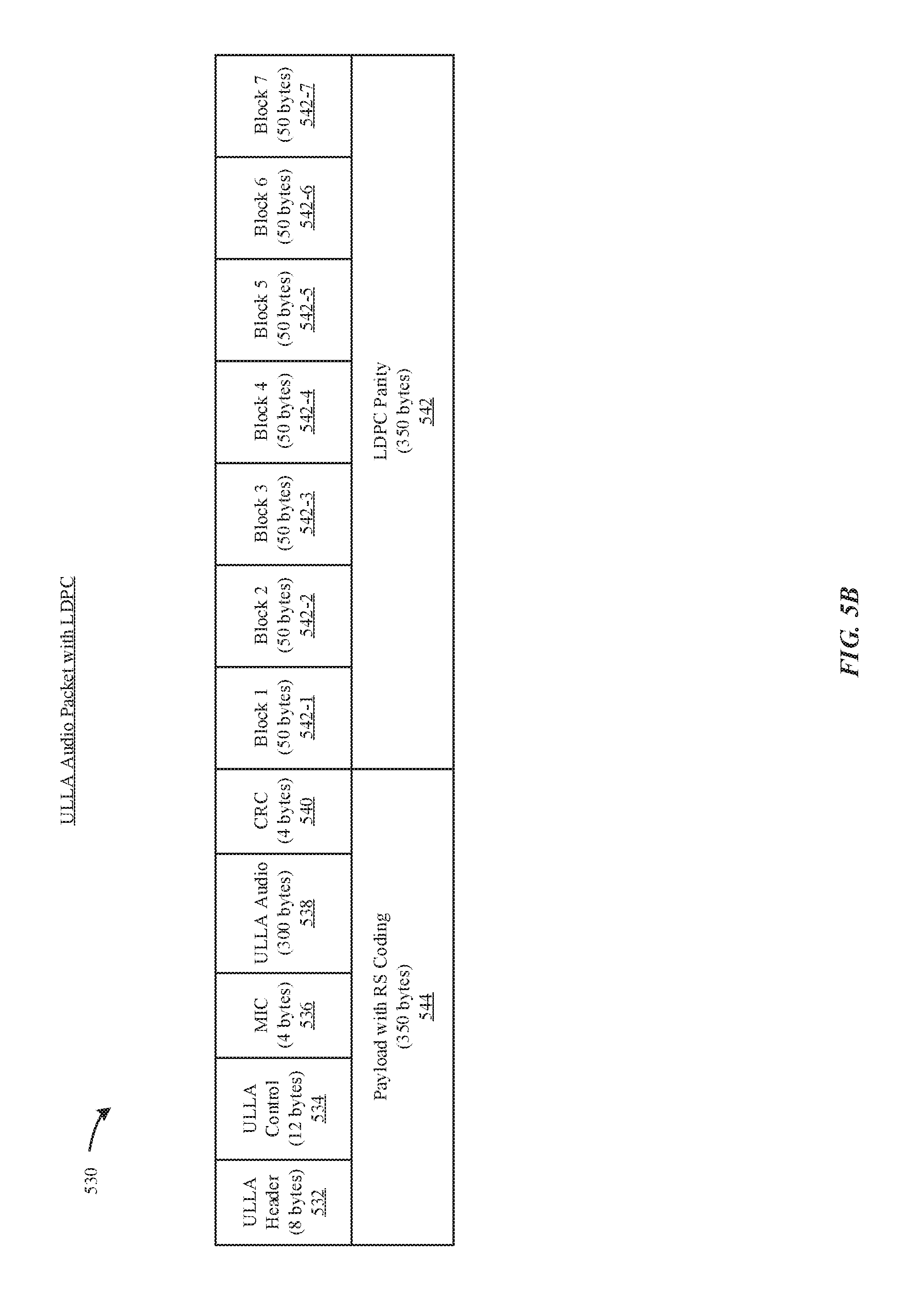
D00014

D00015

D00016

D00017

D00018

D00019
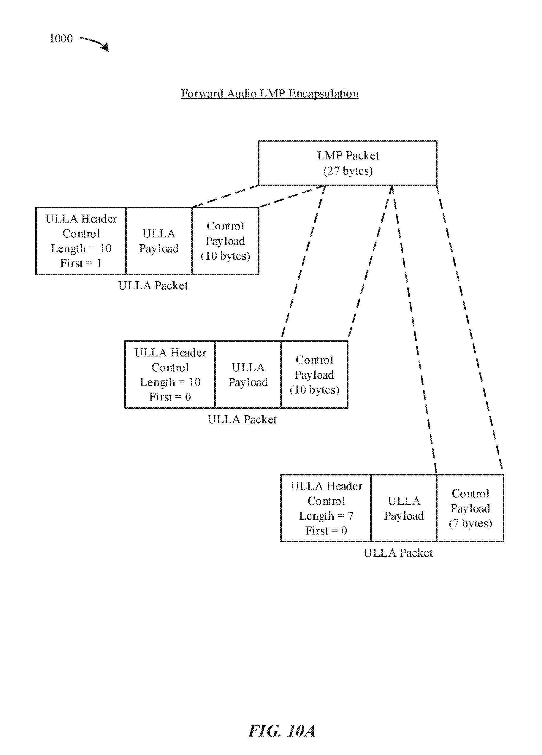
D00020

D00021

D00022

D00023

D00024

XML
uspto.report is an independent third-party trademark research tool that is not affiliated, endorsed, or sponsored by the United States Patent and Trademark Office (USPTO) or any other governmental organization. The information provided by uspto.report is based on publicly available data at the time of writing and is intended for informational purposes only.
While we strive to provide accurate and up-to-date information, we do not guarantee the accuracy, completeness, reliability, or suitability of the information displayed on this site. The use of this site is at your own risk. Any reliance you place on such information is therefore strictly at your own risk.
All official trademark data, including owner information, should be verified by visiting the official USPTO website at www.uspto.gov. This site is not intended to replace professional legal advice and should not be used as a substitute for consulting with a legal professional who is knowledgeable about trademark law.