Efficiency Improved Driver For Laser Diode In Optical Communication
Bazzani; Cristiano ; et al.
U.S. patent application number 16/152171 was filed with the patent office on 2019-04-04 for efficiency improved driver for laser diode in optical communication. The applicant listed for this patent is MACOM Technology Solutions Holdings, Inc.. Invention is credited to Cristiano Bazzani, Chi Mo.
| Application Number | 20190103726 16/152171 |
| Document ID | / |
| Family ID | 65898215 |
| Filed Date | 2019-04-04 |

| United States Patent Application | 20190103726 |
| Kind Code | A1 |
| Bazzani; Cristiano ; et al. | April 4, 2019 |
EFFICIENCY IMPROVED DRIVER FOR LASER DIODE IN OPTICAL COMMUNICATION
Abstract
A circuit and method provide a headroom voltage for a laser driver driving a laser diode such that the laser diode provides signals to an optical communications device. The circuit includes a headroom control circuit receiving the headroom voltage from the laser driver, the headroom control circuit generating a controlled voltage based on the headroom voltage, and a DC-DC converter receiving the controlled voltage from the headroom control circuit generating a voltage Vout based on the controlled voltage, and applying the voltage Vout as an input to the laser diode. The headroom control circuit and the DC-DC converter are connected in a feedback loop with the laser diode to continuously provide the voltage Vout to the laser diode, and the DC-DC converter modifies the voltage Vout to compensate for burn-in characteristics or temperature drift of the laser diode over time to maintain an optimized headroom voltage for the laser driver.
| Inventors: | Bazzani; Cristiano; (Irvine, CA) ; Mo; Chi; (Lowell, MA) | ||||||||||
| Applicant: |
|
||||||||||
|---|---|---|---|---|---|---|---|---|---|---|---|
| Family ID: | 65898215 | ||||||||||
| Appl. No.: | 16/152171 | ||||||||||
| Filed: | October 4, 2018 |
Related U.S. Patent Documents
| Application Number | Filing Date | Patent Number | ||
|---|---|---|---|---|
| PCT/US2018/054257 | Oct 3, 2018 | |||
| 16152171 | ||||
| 62568248 | Oct 4, 2017 | |||
| 62568248 | Oct 4, 2017 | |||
| Current U.S. Class: | 1/1 |
| Current CPC Class: | H03K 4/08 20130101; H02M 2001/0025 20130101; H01S 5/06226 20130101; H02M 3/156 20130101; H02M 1/08 20130101; H02M 3/158 20130101; H01S 5/0428 20130101 |
| International Class: | H01S 5/042 20060101 H01S005/042; H02M 3/158 20060101 H02M003/158 |
Claims
1. A circuit for providing a voltage Vout with an optimized headroom voltage to a laser diode driven by a laser driver, the laser diode configured to provide signals to an optical communications device, comprising: a headroom control circuit having an input connected to receive the headroom voltage from a connection between the laser diode and the laser driver, the headroom control circuit configured to generate a controlled voltage Vc based on the headroom voltage and a modulation current of the laser driver; and a DC-DC converter connected to receive the controlled voltage Vc from the headroom control circuit and to generate the voltage Vout based on the controlled voltage Vc, and to apply the voltage Vout as an input to the laser diode, wherein the headroom control circuit and the DC-DC converter are connected in a feedback loop with the laser diode to continuously provide the voltage Vout to the laser diode, and the headroom control circuit controls the voltage Vc to compensate for high frequency reflections in the laser driver to maintain an optimized headroom voltage for the laser driver.
2. The circuit in accordance with claim 1, wherein the DC-DC converter is configured to generate a control voltage based on the controlled voltage from the headroom control circuit, and to generate driver signals to modify the voltage Vout based on a value of the control voltage.
3. The circuit in accordance with claim 2, wherein the DC-DC converter compares the control voltage to a saw-tooth waveform to generate the driver signals to modify the voltage Vout based on a value of the control voltage.
4. The circuit in accordance with claim 1, wherein the DC-DC converter includes a plurality of switches that are controlled by the driver signals to modify the voltage Vout as needed.
5. The circuit in accordance with claim 1, wherein the headroom control circuit includes at least one programmable current source and/or at least one programmable resistor.
6. The circuit in accordance with claim 5, wherein a value that the at least one programmable current source and/or the at least one programmable resistor are set to control the headroom voltage of the laser driver.
7. The circuit in accordance with claim 6, wherein a change of the value that the at least one programmable current source and/or the at least one programmable resistor are set to controls the headroom voltage of the laser driver and controls the voltage Vout input to the laser diode.
8. A circuit for providing a headroom voltage for a laser driver driving a laser diode, the laser diode configured to provide signals to an optical communications device, comprising: a feedback loop circuit connected between the output of the laser diode and an input of the laser driver, the feedback loop configured to generate a voltage Vout based on the headroom voltage and to apply the voltage Vout to the input of the laser diode, wherein the feedback loop circuit is configured to generate Vout to compensate for high frequency reflections in the laser driver to maintain an optimized headroom voltage for the laser driver.
9. The circuit in accordance with claim 8, wherein the feedback loop circuit comprises: a headroom control circuit having an input connected to receive the headroom voltage from the output of the laser driver, the headroom control circuit configured to generate a controlled voltage based on the headroom voltage; and a DC-DC converter configured to convert the controlled voltage to the voltage Vout, the voltage Vout applied to the input of the laser diode.
10. The circuit in accordance with claim 9, wherein the DC-DC converter is configured to generate a control voltage based on the controlled voltage from the headroom control circuit, and to generate driver signals to modify the voltage Vout based on a value of the control voltage.
11. The circuit in accordance with claim 10, wherein the DC-DC converter compares the control voltage to a saw-tooth waveform to generate the driver signals to modify the voltage Vout based on a value of the control voltage.
12. The circuit in accordance with claim 8, wherein the DC-DC converter includes a plurality of switches that are controlled by the driver signals to modify the voltage Vout as needed.
13. The circuit in accordance with claim 8, wherein the headroom control circuit includes at least one programmable current source and/or at least one programmable resistor and an error and an error amplifier.
14. The circuit in accordance with claim 13, a value that the at least one programmable current source and/or the at least one programmable resistor are set to control the headroom voltage of the laser driver.
15. The circuit in accordance with claim 14, wherein a change of the value that the at least one programmable current source and/or the at least one programmable resistor are set to controls the headroom voltage of the laser driver and controls the voltage Vout input to the laser diode.
16. A method of controlling a headroom voltage of a laser driver, the laser diode being driven by a laser driver, a headroom control circuit connected to receive the headroom voltage of the laser driver, a DC-DC converter connected to receive an output out the headroom control circuit and to output a voltage Vout to an input of the laser diode, the method comprising: generating a controlled voltage based on the headroom voltage with the headroom control circuit; and generating a voltage Vout based on the controlled voltage with the DC-DC converter, and applying the voltage Vout as an input to the laser diode, wherein the headroom control circuit modifies the voltage Vout to compensate for high frequency reflections in the laser driver to maintain an optimized headroom voltage for the laser driver.
17. The method of claim 16, further comprising generating a control voltage based on the controlled voltage from the headroom control circuit, and generating driver signals to modify the voltage Vout based on a value of the control voltage.
18. The method of claim 17, further comprising comparing the control voltage to a saw-tooth waveform to generate the driver signals to modify the voltage Vout.
19. The method of claim 18, further comprising controlling a plurality of switches in the DC-DC converter to modify the voltage Vout.
20. The method of claim 16, further comprising setting a value of at least one programmable current source and/or at least one programmable resistor in the headroom control circuit to set the headroom voltage to a desired value.
Description
1. PRIORITY CLAIM
[0001] This application is a continuation of and claims priority to co-pending PCT Patent Application No. PCT/US2018/054257 filed on Oct. 4, 2018, titled Efficiency Improved Driver For Laser Diode in Optical Communication, which claims priority to and the benefit of U.S. Provisional Patent Application No. 62/568,248 filed on Oct. 4, 2017. This application also claims priority to and the benefit of U.S. Provisional Patent Application No. 62/568,248 filed on Oct. 4, 2017, the contents of which are incorporated by reference in its entirety herein.
2. FIELD OF THE INVENTION
[0002] The present invention relates to laser diodes and to methods of driving laser diodes.
3. BACKGROUND OF THE INVENTION
[0003] Laser diodes have found increasing usage as optical transmitters in fiber optic communications systems. In such systems, the laser diode is typically driven by a constant current from an on-chip laser driver. In some optical transmission systems, an external DC to DC converter may be used to provide a fixed supply voltage for the laser diode from a main input voltage. However, this solution is not ideal. For example, a fixed DC converter output does not compensate for the burn-in characteristics or temperature drift of the laser diode over time. Additionally, if the laser diode is operating at high frequencies, the modulation current in the laser driver can change at high speeds and the DC converter will not be able to adjust the supply voltage to provide sufficient headroom voltage for the laser diode as more or less modulation current flows into the laser and the voltage drop across it changes accordingly.
[0004] The power dissipated on or in the laser driver may be calculated as the constant current multiplied by the headroom across it. Unfortunately, the headroom voltage is not optimized in a typical system, which wastes power. It would improve the whole system efficiency if an optimized and continuously updated headroom voltage for the laser diode could be determined and applied. Besides the advantage of efficiency, an optimized and continuously updated headroom voltage would also automatically compensate for the I-V curve drift over the lifetime of the laser diode and changes due to temperature variations to keep the bias current constant.
SUMMARY
[0005] Aspects of embodiments of the invention include a circuit and method that provide a headroom voltage for a laser diode driver driving the laser diode providing signals to an optical communications device. The circuit includes a headroom control circuit receiving the headroom voltage from the laser driver, the headroom control circuit generating a controlled voltage Vc based on the headroom voltage and a modulation current of the laser driver, and a DC-DC converter receiving the controlled voltage from the headroom control circuit and generating a voltage Vout based on the controlled voltage, and applying the voltage Vout as a supply to the laser diode. The headroom control circuit and the DC-DC converter are connected in a feedback loop with the laser diode to continuously provide the voltage Vout to the laser diode, and the headroom control circuit controls the voltage Vc to compensate for high frequency reflections in the laser driver due to high frequency modulation current to maintain an optimized headroom voltage for the laser driver.
[0006] In further aspects of embodiments of the invention, the DC-DC converter is configured to generate a control voltage based on the input of the headroom control circuit, and to generate driver signals to modify the voltage Vout based on a value of the input. The DC-DC converter may compare the control voltage to a saw-tooth waveform to generate the driver signals to modify the voltage Vout based on a value of the input. Other DC-DC converter implementations and/or control scheme can be implemented. In one embodiment, the DC-DC converter includes a plurality of switches that are controlled by the driver signals to modify the voltage Vout as needed.
[0007] It is also contemplated that the headroom control circuit includes at least one programmable current source and/or at least one programmable resistor. In further aspects of embodiments of the invention, a value that the at least one programmable current source and/or the at least one programmable resistor are set to control the headroom voltage of the laser driver. In one variation, a change of the value that the at least one programmable current source and/or the at least one programmable resistor are set to controls the headroom voltage of the laser driver and controls the voltage Vout supply to the laser diode.
[0008] In further aspects of embodiments of the invention, a circuit provides a headroom voltage for a laser driver driving a laser diode, the laser diode configured to provide signals to an optical communications device. The circuit comprises a feedback loop circuit connected between the output of the laser diode and an input of the laser driver such that the feedback loop is configured to generate a voltage Vout based on the headroom voltage and to apply the voltage Vout to the input of the laser diode. The feedback loop circuit is configured to generate Vout to compensate for burn-in characteristics and/or temperature drift of the laser diode over time to maintain an optimized headroom voltage for the laser driver.
[0009] Also contemplated for the circuit such that the feedback loop circuit comprises a headroom control circuit having an input connected to receive the headroom voltage from the output of the laser driver. The headroom control circuit is configured to generate a controlled voltage based on the headroom voltage. And, a DC-DC converter configured to convert the controlled voltage to the voltage Vout such that the voltage Vout is applied to the input of the laser diode. In one embodiment, the DC-DC converter is configured to generate a control voltage based on the controlled voltage from the headroom control circuit and to generate driver signals to modify the voltage Vout based on a value of the control voltage. The DC-DC converter may compare the control voltage to a saw-tooth waveform to generate the driver signals to modify the voltage Vout based on a value of the control voltage.
[0010] In one embodiment, the DC-DC converter includes a plurality of switches that are controlled by the driver signals to modify the voltage Vout as needed. The headroom control circuit may include at least one programmable current source and/or at least one programmable resistor. In one variation, a value that the at least one programmable current source and/or the at least one programmable resistor are set to control the headroom voltage of the laser driver. A change of the value that the at least one programmable current source and/or the at least one programmable resistor are set to may control the headroom voltage of the laser driver and controls the voltage Vout input to the laser diode.
[0011] Also disclosed is a method of controlling a headroom voltage of a laser driver with the laser diode being driven by the laser driver and a headroom control circuit connected to receive the headroom voltage of the laser driver while a DC-DC converter connects to receive an output out the headroom control circuit and to output a voltage Vout to an input of the laser diode. This method comprises generating a controlled voltage based on the headroom voltage with the headroom control circuit and generating a voltage Vout based on the controlled voltage with the DC-DC converter, and then applying the voltage Vout as an input to the laser diode, such that the DC-DC converter modifies the voltage Vout to compensate for burn-in characteristics or temperature drift of the laser diode over time to maintain an optimized headroom voltage for the laser driver.
[0012] In one embodiment, the method further comprising generating a control voltage based on the controlled voltage from the headroom control circuit and generating driver signals to modify the voltage Vout based on a value of the control voltage. The method may further comprise comparing the control voltage to a saw-tooth waveform to generate the driver signals to modify the voltage Vout. In one configuration the method further comprises controlling a plurality of switches in the DC-DC converter to modify the voltage Vout. This method may also set a value of at least one programmable current source and/or at least one programmable resistor in the headroom control circuit to set the headroom voltage to a desired value.
[0013] Other systems, methods, features and advantages of the invention will be or will become apparent to one with skill in the art upon examination of the following figures and detailed description. It is intended that all such additional systems, methods, features and advantages be included within this description, be within the scope of the invention, and be protected by the accompanying claims.
BRIEF DESCRIPTION OF THE DRAWINGS
[0014] The components in the figures are not necessarily to scale, emphasis instead being placed upon illustrating the principles of the invention. In the figures, like reference numerals designate corresponding parts throughout the different views.
[0015] FIG. 1 illustrates a block diagram of a circuit for providing a voltage for a laser diode, the laser diode providing signals to fiber optics, in accordance with embodiments of the present invention.
[0016] FIG. 2 illustrates a DC-to-DC converter for providing a voltage to the laser diode in accordance with embodiments of the present invention.
[0017] FIG. 3 illustrates a schematic diagram of a laser diode driver and associated circuitry for providing high speed current signals with optimized headroom to drive a laser diode in accordance with embodiments of the present invention.
[0018] FIG. 4 illustrates a schematic diagram of the headroom control circuit (REGREF) and associated circuitry of FIG. 3, with the associated circuitry shown in detail, in accordance with embodiments of the present invention.
[0019] FIG. 5 illustrates a flowchart in accordance with embodiments of the present invention.
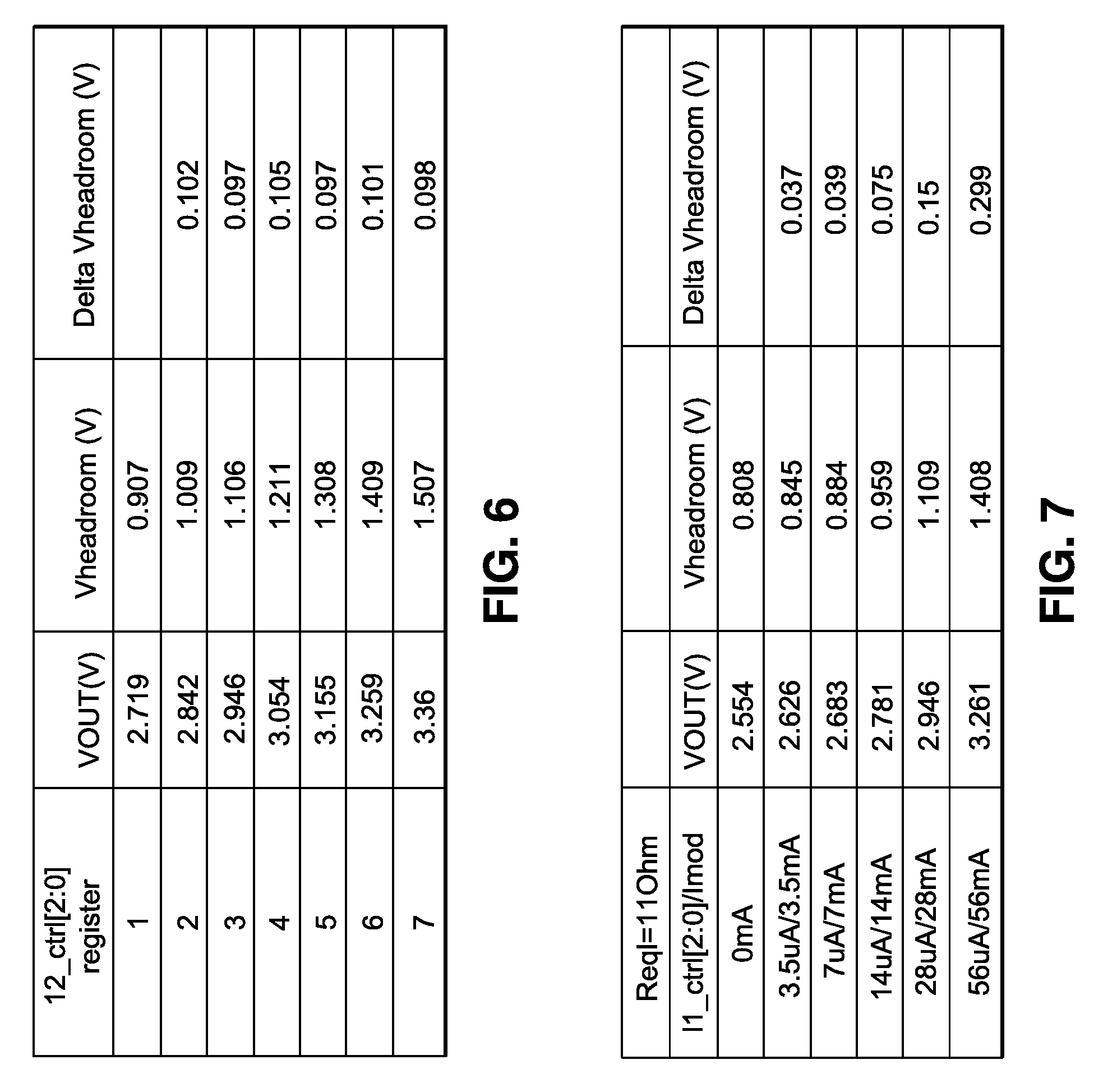
[0020] FIG. 6 illustrates test results of different Vout, Vheadroom and Delta Vheadroom values obtained when varying the programmable current source I2.
[0021] FIG. 7 illustrates test results of different Vout, Vheadroom and Delta Vheadroom values obtained when varying the programmable current source I1.
DETAILED DESCRIPTION OF PREFERRED EMBODIMENTS
[0022] In the following description, numerous specific details are set forth in order to provide a more thorough description of embodiments of the present invention. It will be apparent, however, to one skilled in the art, that the embodiments of the present invention may be practiced without these specific details. In other instances, well-known features have not been described in detail so as not to obscure the embodiments of the present invention.
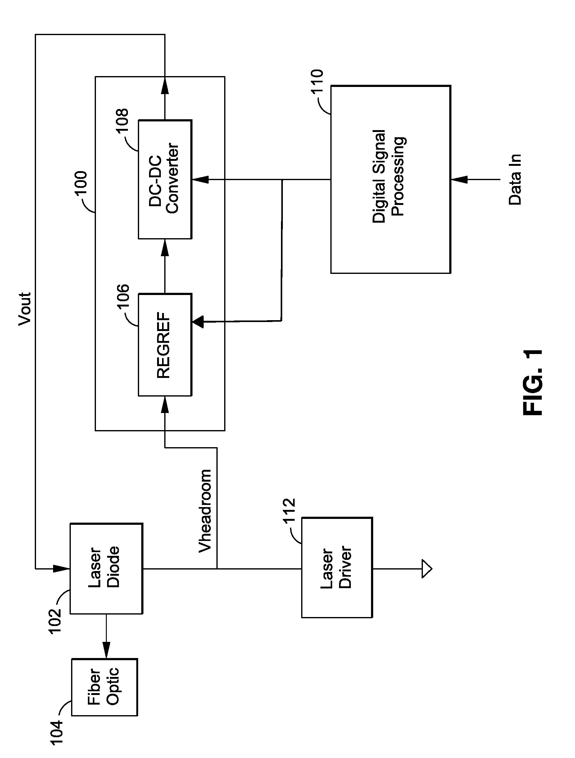
[0023] FIG. 1 illustrates a block diagram of a circuit 100 for providing an optimized headroom to a laser diode 102. The laser diode 102 of FIG. 1 may be used to provide signals in optical communications, such as providing signals to optical fiber 104, for example of for free space communications. However, other uses of the laser diode 102 may also be utilized with preferred embodiments of the invention.
[0024] Headroom is defined herein as the difference between the supply voltage and the sum of the individual voltage drops along a single circuit path. The headroom for a laser driver as shown in FIG. 1 would be the voltage applied to the laser diode (Vout) minus the drop across the laser diode and any circuitry associated with the driver disposed between the laser diode 102 and Vout. A laser driver such as npn transistors 304 and 305 shown in FIG. 3 typically may need about 0.7V of headroom.
[0025] If the voltage at the laser diode input (Vout) were 3.3 volts (as defined for VccT by the SFP+High Speed Electrical Interface Standard SFF-8431), then the headroom for the laser driver may be insufficient due to the above-described voltage drop increase. Accordingly, embodiments of the present invention continuously adjust the voltage Vout to provide an optimized headroom for the laser driver.
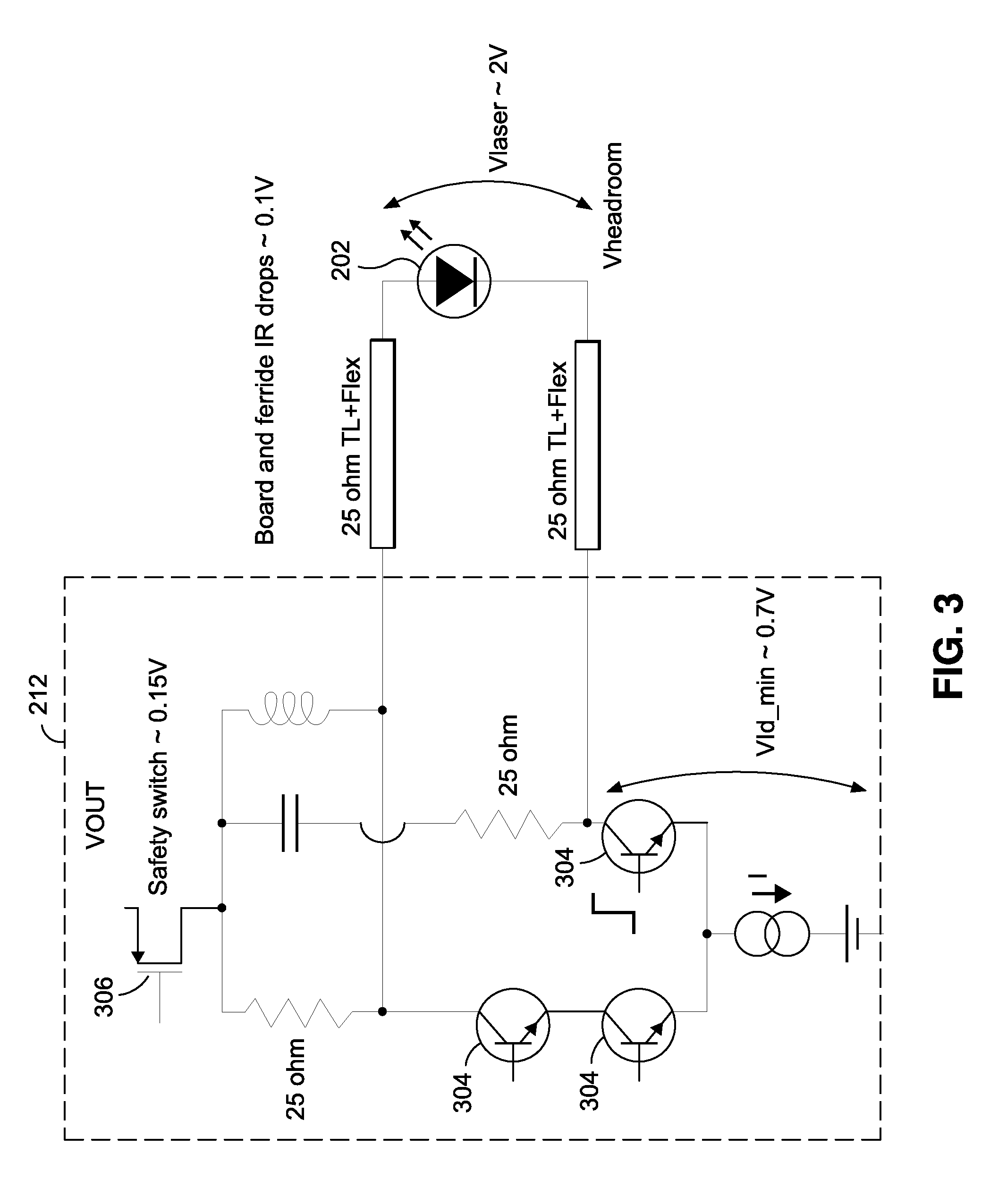
[0026] Additionally, the laser driver 212 is operated at high frequency in turning on and off the laser diode 102 by sending pulses of current into the laser diode 102, 202, typically using a square wave signal having a very sharp edge. In turning on and off the laser, the current in the circuit is sent through the laser diode 202 (when the laser diode is turned on) or through the branch of the circuit of FIG. 3 including the bipolar transistors 304 (when the laser diode is turned off).
[0027] However, because of the high frequency effects, when the square pulse is applied, in the beginning only the characteristic impedance of the load is applied (for example 25 Ohms in the case of DML lasers) because the signal has not yet traveled along the transmission line, but when the signal travels along the transmission line and is reflected back, an additional peak of voltage is present which is typically equal to the modulation current I mod times the resistance equivalent of the laser Reql. The Reql of a laser is a quantity that depends on the physical dimensions and manufacturing characteristics of the laser and optical subassembly construction (bond wires leading to the laser, flex-cables connecting the laser driver board to the laser, etc.). This peak voltage is typically about 1V. After the edge of the square wave has passed, now a continuous mode type of condition of is present and current is flowing into the laser diode, and the drop across the laser diode 202 is equal to the diode voltage of the laser plus the dc resistance of the laser times the current. The dc resistance of the laser diode is smaller than the Reql of the laser diode (the high frequency resistance of the laser diode). To make the driver not be compressed during the transition between turning off and on of the laser diode, a higher voltage needs to be applied than during purely DC operation due to the additional peak voltage.
[0028] As shown in FIG. 3 illustrating the laser driver 212 in further detail, in typical DML applications, Vout must be about 4V or greater to provide sufficient headroom to the n-p-n transistors 304, 305 of the laser driver considering the associated voltage drops across the laser diode 202 and the circuitry associated with the laser driver 212 when considering the high frequency effects. For an extreme example, the safety switch 306 may have a voltage drop of .about.0.15V, the board and ferride voltage drops may be .about.0.1V, the voltage drop across the laser diode 202 may be .about.2.0V and as explained above, the peak voltage may be about 1.0V reflected back from the transmission line. Thus, to provide the needed headroom voltage of .about.0.7V, Vout should be .about.0.15V+0.1V+2.0V+0.7V+1.0V, or around 4.0V. This would prove problematic using a module with a 3.3V supply. Accordingly, embodiments of the present invention can provide a Vout of approximately 4.0V or greater for worst case conditions.
[0029] The circuit 100 of FIG. 1 for providing an optimized headroom to the laser diode 102 includes a REGREF 106 and a DC-DC converter 108. The REGREF 106 is a headroom control circuit that provides a controlled voltage to the DC-DC converter 108. The DC-DC converter 108 is configured to convert the voltage provided by the REGREF 106 to a voltage Vout, which is used as an input to the laser diode 102. The digital signal processing 110 will monitor the performance of the laser diode and processes to send appropriate signals to the DC-DC converter 108, for modulation of the output voltage Vout, so that data can be provided to the fiber optic 104 with a low error rate.
[0030] The REGREF 106 receives as digital command from digital signal processing 110 and an input a voltage Vheadroom from the output of the laser driver 112, which may be used in a feedback loop to adjust the voltage Vout applied as an input to laser diode 102. The headroom voltage of the laser driver may be adjusted by the REGREF 106 to provide a desired headroom voltage and to automatically compensate for changes in the modulation current.
[0031] The laser driver 112, 212 modulates the current in the laser diode 102 to transmit the optical signal at 28 Gbps, although other speeds could be used. The average current required by the laser diode 102, 202 changes as a function of temperature as well as aging effects. The voltage drop across the laser diode 102 will change accordingly. The DC-DC converter 108 account for or react to the very high frequency reflections created by the mismatch impedance of the laser driver 112 with respect to the laser diode 102. This reflection depends on the impedances at play in the system (in particular laser bonding inductances) and is fairly constant for a given system. This is referred to herein as equivalent laser resistance or Reql. These reflections are also proportional to the modulation current (Imod).
[0032] The laser driver 112 may be a DML (direct modulated laser) driver. To guarantee the DML driver performance, the headroom should be:
Vheadroom=Vld_min+I mod*Reql (1)
where Vld_min is the minimum dc voltage at the output of the laser driver to guarantee performance (this is usually determined by the design and is in the order of 0.7V), Reql is the equivalent impedance of the laser diode 102, 202 which is proportional to the reflection from the transmission line, and Imod is the modulation current in the laser diode 102. As explained above Reql*Imod is typically about 1.0V.
[0033] The power dissipation in the laser driver 112 can be calculated as in equation (2) below. Equation (2) shows that the power dissipation (Pdiss) equals the headroom voltage (Vheadroom) times the average modulation current (Iave). If the headroom voltage is too low, the laser driver performance will suffer and error rate will increase. If the headroom voltage is too high, not only will the power dissipation be suboptimal, but also there is a risk of breakdown for the high frequency bipolar transistors 304 used in the laser driver 112.
Pdiss=Vheadroom*Iave (2)
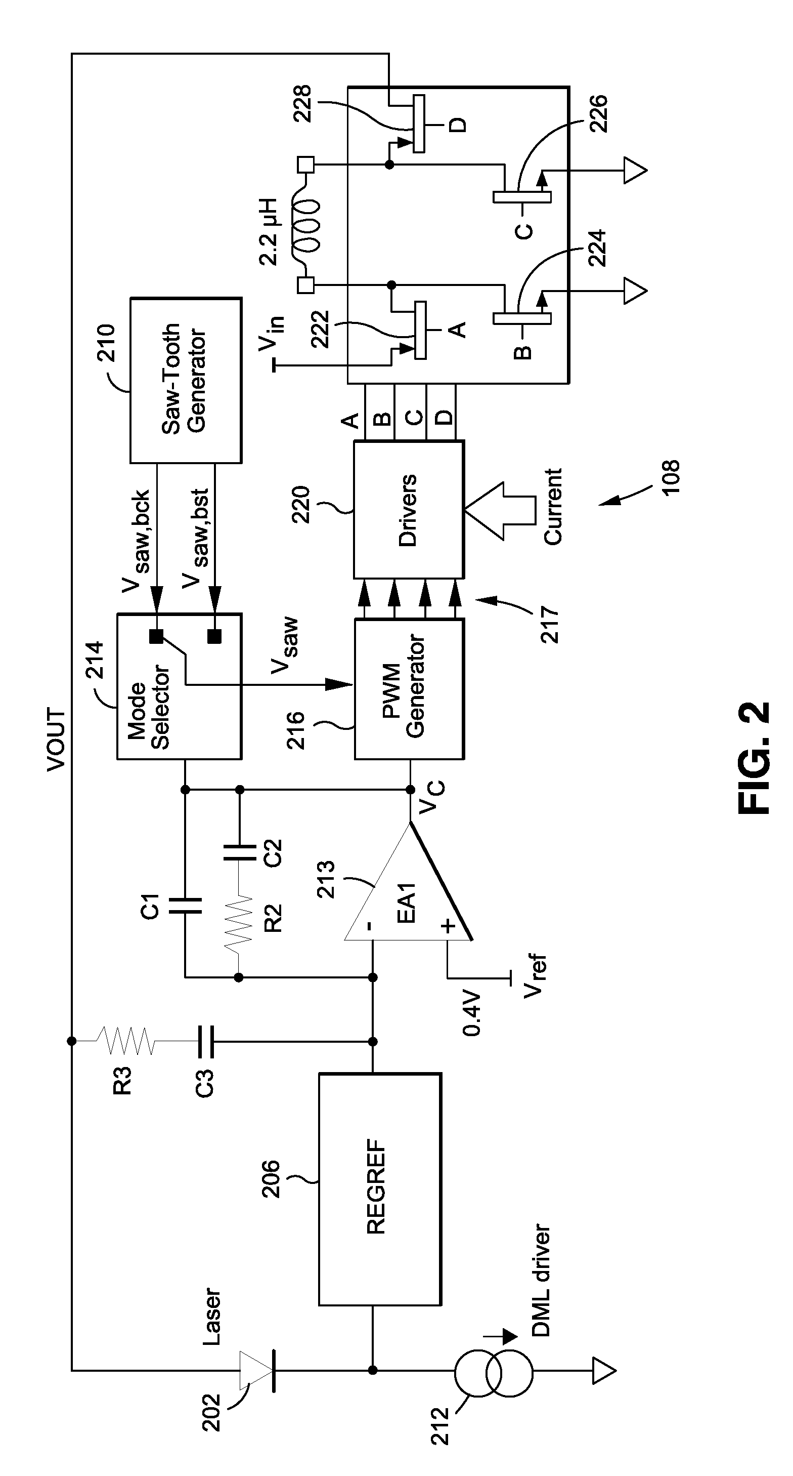
[0034] Further details of the DC-DC converter 108 and its connection to the REGREF 206, laser diode 202 and laser driver 212 are illustrated in FIG. 2. The DC-DC converter 108 outputs voltage Vout to the laser diode 202, which is driven by the laser driver 212. The REGREF 206 adjusts the voltage received at its input to output a voltage to error amplifier EA1 213, with a voltage of 0.4V applied at the positive input of EA1 213 to produce control voltage Vc.
[0035] The saw-tooth generator 218 generates saw tooth waveforms Vsaw.bck and Vsaw.bst, which are selected under the control of mode selector 214 to output saw-tooth waveform Vsaw. The saw-tooth waveforms may be 2.5 Mhz saw-tooth waveforms, although other waveforms could be used. The saw-tooth waveform is compared with Vc in the PWM generator 216 to generate the PWM modulated signals 217 used by drivers 220 to generate the PWM modulated signals A, B, C and D, which are used to control the transistors 222, 224, 226 and 228 to produce the desired Vout. Appropriate control of the transistors 222, 224, 226 and 228 is used to raise or lower Vout as needed, such that a Vout can be provided between approximately 2.0V and 4.5V.
[0036] The REGREF 106, 206 will adjust the headroom voltage to automatically compensate for the I-V curve drift over the lifetime of the laser diode 202 and compensate for changes in temperature to keep the bias current constant. For example, if the voltage drop across the laser diode 202 were to change due to a change in temperature or due to drift over time, the voltage at the output of the laser driver (Vheadroom) would change and could become too low or too high to provide a headroom with optimal performance. For example, if the voltage Vheadroom was reduced due to a change in temperature and a bigger voltage drop across the laser diode 202, the voltage at the output of REGREF 206 and input to error amplifier EA1 213 would be lowered, resulting in a changed control voltage Vc. The changed control voltage Vc, would result in a changed Vout being applied to the laser diode 202.
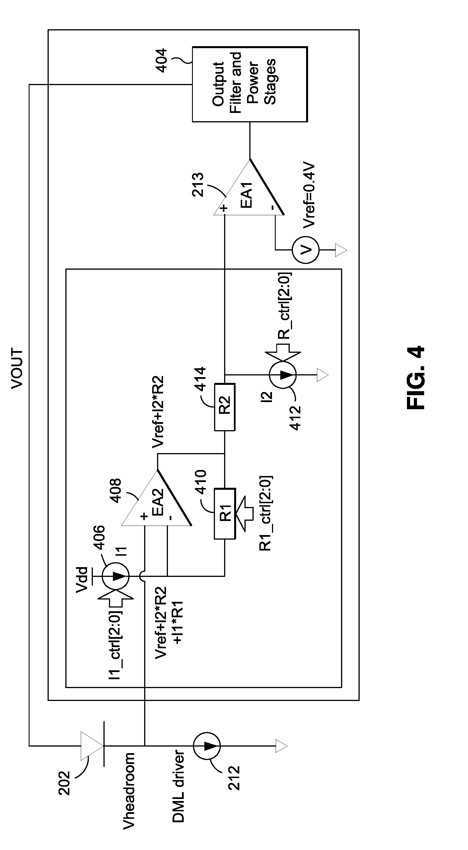
[0037] The REGREF 206 is shown in further detail in FIG. 4, along with its connection to the laser diode 202, laser driver 212 and DC-DC converter. The REGREF 206 includes an error amplifier EA2 and a set of programmable resistors R1 410 and R2 414 and programmable current sources I1 406 and I2 412. The headroom voltage Vheadroom at the laser driver 212 is input to the positive input of the error amplifier EA2, and a voltage generated at the output of I1 406 (I1*R1) is input to the negative input of the error amplifier EA1 213. The voltage at the output of the error amplifier EA2 408 is Vref+I2*R2. When the feedback loop is closed through the DC-DC converter, the voltage Vout will self-adjust in such a way that equation (3) is satisfied:
Vheadroom=Vref+R2*I2+R1*I1 (3)
[0038] I1 is used to generate a voltage (I1*R1) which when added to R2*I2 and Vref at EA1 creates the minimum voltage required by the laser driver for operation Vld_min as shown in equation (4) where I1 and R1 are held constant. This minimum voltage for laser driver operation is typically about 0.7V.
Vld_min=R2*I2+Vref (4)
I mod*Reql+I1*R1 (5)
[0039] Importantly, I1 is configured to track the changes in the modulation current of the laser driver 212. This could be accomplished in many ways, such as using a monitoring circuit to monitor changes in the modulation current of the laser driver 212 with the monitoring circuit configured to make corresponding or proportional changes in the programmable current source I1 406.
[0040] In closed loop operation, the REGREF 106, 206 will adjust Vc and thus Vout to ensure that equation (3) is valid regardless of the laser diode operation voltage (which may change with temperature/aging) and other IR drops due to board/ferride resistance and the voltage drop of the safety switch (See FIG. 3).
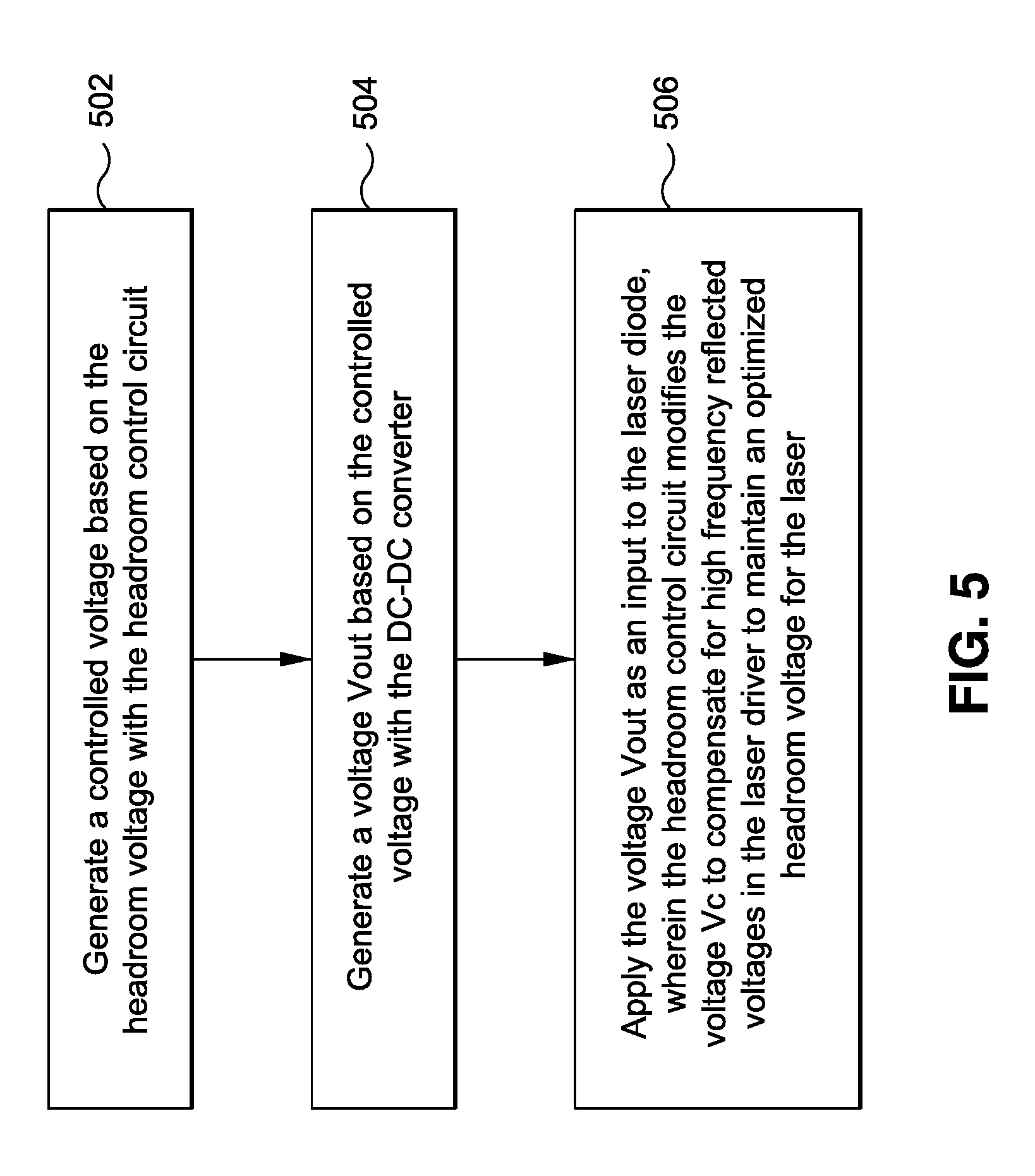
[0041] FIG. 5 illustrates a flowchart according to embodiments of the invention. In step 502, the headroom control circuit REGREF generates a controlled voltage based on the headroom voltage Vheadroom. In step 504, the DC-DC converter generates a voltage Vout based on the controlled voltage received from the headroom control circuit.
[0042] In step 506, the voltage Vout is applied as an input to the laser diode, wherein the DC-DC converter modifies the voltage Vout to compensate for burn-in characteristics or temperature drift of the laser diode over time to maintain an optimized headroom voltage for the laser driver.
[0043] FIG. 6 illustrates test results of the headroom control circuit REGREF 206 with changes in a control bit I2_ctrl [2:0] that changes the current injected at programmable current source I2 412 with R1, I1 and R2 held constant. As shown in FIG. 6, each step will change the Vout and Vheadroom by about 100 mV. This allows a user of the embodiments of the invention to set a desired headroom Vheadroom by adjusting the programmable current source I2 412. Different currents may be used to produce higher or lower headroom Vheadroom as desired.
[0044] FIG. 7 illustrates test results of the headroom control circuit REGREF 206 with changes in an injected current applied at programmable current source I1 406. This test set R1 to 11K Ohms and changes the value of I1 with I2 and R2 held constant. For every 3.5 A change in I1, the headroom voltage Vheadroom changes by about 38 mV. This allows a user of the embodiments of the invention to set a desired headroom Vheadroom by adjusting the programmable current source I1 406. Different currents may be used to produce higher or lower headroom Vheadroom as desired.
[0045] While various embodiments of the invention have been described, it will be apparent to those of ordinary skill in the art that many more embodiments and implementations are possible that are within the scope of this invention. In addition, the various features, elements, and embodiments described herein may be claimed or combined in any combination or arrangement
* * * * *
D00000
D00001
D00002
D00003
D00004
D00005
D00006
XML
uspto.report is an independent third-party trademark research tool that is not affiliated, endorsed, or sponsored by the United States Patent and Trademark Office (USPTO) or any other governmental organization. The information provided by uspto.report is based on publicly available data at the time of writing and is intended for informational purposes only.
While we strive to provide accurate and up-to-date information, we do not guarantee the accuracy, completeness, reliability, or suitability of the information displayed on this site. The use of this site is at your own risk. Any reliance you place on such information is therefore strictly at your own risk.
All official trademark data, including owner information, should be verified by visiting the official USPTO website at www.uspto.gov. This site is not intended to replace professional legal advice and should not be used as a substitute for consulting with a legal professional who is knowledgeable about trademark law.