Physical Button For Touch Screen
LAPALME; Andre ; et al.
U.S. patent application number 16/150543 was filed with the patent office on 2019-04-04 for physical button for touch screen. The applicant listed for this patent is BLUBERI GAMING CANADA INC.. Invention is credited to Eric BEAUDOIN, Andre LAPALME, Yvan PARADIS.
| Application Number | 20190102969 16/150543 |
| Document ID | / |
| Family ID | 65898009 |
| Filed Date | 2019-04-04 |


View All Diagrams
| United States Patent Application | 20190102969 |
| Kind Code | A1 |
| LAPALME; Andre ; et al. | April 4, 2019 |
PHYSICAL BUTTON FOR TOUCH SCREEN
Abstract
A control button for installation on a touchscreen display responding upon contact of an electrical conductor. The control button comprises a central portion comprising a touch sensitive component which has an electrical characteristic changed when touched by a user, and a body comprising electrical contacts and biasing device. The control button adopts at least one of a non-conducting position and a conducting position, whereby the biasing device biases the control button toward the non-conducting position. Upon pressure being applied by a user over the central portion, the control button moves from the non-conducting position until the control button reaches the conducting position, whereby in the conducting position an electrical circuit is completed from the touch sensitive component to the touchscreen display through the electrical contacts. The control button is further mounted to a gaming machine.
| Inventors: | LAPALME; Andre; (Drummondville, CA) ; PARADIS; Yvan; (Drummondville, CA) ; BEAUDOIN; Eric; (Drummondville, CA) | ||||||||||
| Applicant: |
|
||||||||||
|---|---|---|---|---|---|---|---|---|---|---|---|
| Family ID: | 65898009 | ||||||||||
| Appl. No.: | 16/150543 | ||||||||||
| Filed: | October 3, 2018 |
Related U.S. Patent Documents
| Application Number | Filing Date | Patent Number | ||
|---|---|---|---|---|
| 62567562 | Oct 3, 2017 | |||
| Current U.S. Class: | 1/1 |
| Current CPC Class: | G07F 17/3211 20130101; G06F 3/0416 20130101; G06F 3/044 20130101; G07F 17/248 20130101; G06F 3/0393 20190501; H05K 5/0017 20130101; G06F 3/0414 20130101; G07F 17/3209 20130101; G07F 17/3216 20130101; G07F 17/3288 20130101; G06F 3/03547 20130101 |
| International Class: | G07F 17/32 20060101 G07F017/32; G06F 3/044 20060101 G06F003/044; G06F 3/041 20060101 G06F003/041; G06F 3/0354 20060101 G06F003/0354 |
Claims
1. A control button for installation on a touchscreen display responding upon contact by an electrical conductor, the control button comprising: a central portion comprising a touch sensitive component having an electrical characteristic that changes upon contact of a user's skin or by an electrical conductor; and a body comprising electrical contacts and a biasing device; wherein the control button adopts at least one of a non-conducting position and a conducting position, whereby the biasing device biases the control button toward the non-conducting position, and wherein, upon pressure being applied by the user to the central portion, the control button moves from the non-conducting position until the control button reaches the conducting position, whereby in the conducting position an electrical circuit is completed from the touch sensitive component to the touchscreen display through the electrical contacts.
2. The control button of claim 1, wherein the central portion is translucent, whereby a portion of an image displayed on the touchscreen display is visible through the central portion.
3. The control button of claim 2, further comprising a lens inset in the body, wherein an image displayed by the touchscreen display under the lens is transmitted through the lens and visible through the central portion.
4. The control button of claim 1, wherein the central portion comprises a contact surface to be contacted by the user, and wherein the contact surface is flat.
5. The control button of claim 1, wherein the body is ring-shaped.
6. The control button of claim 1, wherein the touch sensitive component comprises a Surface Capacitive (SCAP) component.
7. The control button of claim 1, further comprising a clicker generating a clicking sound upon the control button moving from the non-conducting position to the conducting position thereby confirming to the user that the touch screen responds to the user's input.
8. The control button of claim 1, wherein the body comprises a bottom face and an outer face, wherein the body comprise light transmissive material connecting the bottom face to the outer face, the light transmissive material transmitting light emitted by the touchscreen display under the bottom face to the outer face.
9. The control button of claim 8, wherein the body further comprises an inner face, wherein the inner face comprises an opaque surface.
10. A gaming machine comprising: a gaming machine cabinet housing a processor; a memory functionally connected to the processor, wherein the memory stores data processable as a wagering game comprising steps comprising receiving player inputs, selecting an outcome among potential outcomes and generating visuals associated with the outcome; a first display connected to the processor to display at least part of the visuals; a touchscreen display connected to the processor, the touchscreen display comprising a display surface for displaying images and a touch sensitive component responding upon contact of an electrical conductor; and a control button mounted to the display surface of the touchscreen display, comprising a translucent central portion through which at least part of the images displayed by the touchscreen display are visible to the player, and a body surrounding the central portion, wherein pressure applied by the player over the control button generates an input signal transmitted to the processor through the touchscreen display.
11. The gaming machine of claim 10, wherein the display surface of the touchscreen display comprises an input portion free from the control button, wherein the input portion is adapted to be directly contacted by the player to generate another input signal.
12. The gaming machine of claim 11, wherein the processor interprets the input signal and the other signal as different inputs resulting in different processes.
13. The gaming machine of claim 10, wherein the control button comprises a touch sensitive component which has an electrical characteristic changed when contacted by the player.
14. The gaming machine of claim 13, wherein the body of the control button further comprises an electrical contact, wherein an electrical circuit is completed from the touch sensitive component to the touchscreen display through the electrical contact.
15. The gaming machine of claim 13, wherein the control button is able to adopt a non-conducting position and a conducting position, and wherein the electrical contact further comprises an electrical interface contacting the touchscreen display only when the control button is in the conducting position.
16. The gaming machine of claim 10, wherein the control button comprises a Surface Capacitive (SCAP) component.
17. The gaming machine of claim 10, wherein the control button comprises biasing means responding to pressure applied by the player over the control button, wherein the pressure results in the control button passing from a non-conducting position to a conducting position.
18. The gaming machine of claim 17, further comprising a clicker generating a clicking sound upon the control button passing from the non-conducting position to the conducting position.
19. The gaming machine of claim 10, wherein the gaming machine further comprises a lens inset in the body of the control button, wherein an image displayed by the touchscreen display under the lens is transmitted through the lens and visible through the central portion.
20. The gaming machine of claim 10, wherein the body comprises a bottom face and an outer face, and wherein the body comprise light transmissive material connecting the bottom face to the outer face, the light transmissive material transmitting light emitted by the touchscreen display under the bottom face to the outer face.
Description
CROSS-REFERENCE TO RELATED APPLICATION
[0001] This application claims priority from U.S. provisional patent application 62/567,562 filed Oct. 3, 2017, the specification of which is hereby incorporated herein by reference in its entirety.
BACKGROUND
(a) Field
[0002] The subject matter herein disclosed generally relates to wagering game machines. More particularly, the subject matter disclosed relates to control components in wagering game machines.
(b) Related Prior Art
[0003] The purpose of indicia on paper is to convey information. While this is also true for visual effects in wagering game machines, images and indicia displayed by a wagering game's display device have the additional extremely important purpose of providing or increasing entertainment for the player. If some players are not entertained, they will not play on a wagering game machine. Also, more recently, players have come to expect more entertainment from wagering game devices, for example, those having video displays rather than the older mechanical displays.
[0004] Since one of the primary purposes of a wagering game machine is to provide entertainment, there is a major challenge for gaming device manufacturers to develop new games that provides increased entertainment. Players are entertained not only by the risk of a wager but also by attractive, engaging, interesting, fun, new and different visual, audio, and audio-visual effects. For those reasons, the gaming industry is constantly seeking to make advancements in games and in the devices and components on which are played these games. If one views a wagering game machine as only a wagering mechanism, the display or graphical aspect of the wagering game machine may appear to have little value. However, by remembering that a wagering game machine is an entertainment device as well as, or in addition to, a wagering device, the importance of an interesting and exciting graphical display and the technical challenges faced by gaming personnel to develop such displays becomes apparent. Simultaneously, to maintain certain player's interest in a wagering game machine for a significant period of time, the games and the wagering game machines on which they run must be highly interesting, entertaining, enjoyable and to minimize fatigue.
[0005] There is therefore a need for continuous improvement and development in the field of wagering game machines.
SUMMARY
[0006] According to an embodiment, there is provided a control button for installation on a touchscreen display responding upon contact by an electrical conductor, the control button comprising: a central portion comprising a touch sensitive component having an electrical characteristic that changes upon contact of a user's skin or by an electrical conductor; and a body comprising electrical contacts and a biasing device; wherein the control button adopts at least one of a non-conducting position and a conducting position, whereby the biasing device biases the control button toward the non-conducting position, and wherein, upon pressure being applied by the user to the central portion, the control button moves from the non-conducting position until the control button reaches the conducting position, whereby in the conducting position an electrical circuit is completed from the touch sensitive component to the touchscreen display through the electrical contacts.
[0007] According to an aspect, the central portion is translucent, whereby a portion of an image displayed on the touchscreen display is visible through the central portion.
[0008] According to an aspect, the control button further comprises a lens inset in the body, wherein an image displayed by the touchscreen display under the lens is transmitted through the lens and visible through the central portion.
[0009] According to an aspect, the central portion comprises a contact surface to be contacted by the user, and wherein the contact surface is flat.
[0010] According to an aspect, the body is ring-shaped.
[0011] According to an aspect, the touch sensitive component comprises a Surface Capacitive (SCAP) component.
[0012] According to an aspect, the control button further comprises a clicker generating a clicking sound upon the control button moving from the non-conducting position to the conducting position thereby confirming to the user that the touch screen responds to the user's input.
[0013] According to an aspect, the body comprises a bottom face and an outer face, wherein the body comprise light transmissive material connecting the bottom face to the outer face, the light transmissive material transmitting light emitted by the touchscreen display under the bottom face to the outer face.
[0014] According to an aspect, the body further comprises an inner face, wherein the inner face comprises an opaque surface.
[0015] According to an embodiment, there is provided a gaming machine comprising: a gaming machine cabinet housing a processor; a memory functionally connected to the processor, wherein the memory stores data processable as a wagering game comprising steps comprising receiving player inputs, selecting an outcome among potential outcomes and generating visuals associated with the outcome; a first display connected to the processor to display at least part of the visuals; a touchscreen display connected to the processor, the touchscreen display comprising a display surface for displaying images and a touch sensitive component responding upon contact of an electrical conductor; and a control button mounted to the display surface of the touchscreen display, comprising a translucent central portion through which at least part of the images displayed by the touchscreen display are visible to the player, and a body surrounding the central portion, wherein pressure applied by the player over the control button generates an input signal transmitted to the processor through the touchscreen display.
[0016] According to an aspect, the display surface of the touchscreen display comprises an input portion free from the control button, wherein the input portion is adapted to be directly contacted by the player to generate another input signal.
[0017] According to an aspect, the processor interprets the input signal and the other signal as different inputs resulting in different processes.
[0018] According to an aspect, the control button comprises a touch sensitive component which has an electrical characteristic changed when contacted by the player.
[0019] According to an aspect, the body of the control button further comprises an electrical contact, wherein an electrical circuit is completed from the touch sensitive component to the touchscreen display through the electrical contact.
[0020] According to an aspect, the control button is able to adopt a non-conducting position and a conducting position, and wherein the electrical contact further comprises an electrical interface contacting the touchscreen display only when the control button is in the conducting position.
[0021] According to an aspect, the control button comprises a Surface Capacitive (SCAP) component.
[0022] According to an aspect, the control button comprises biasing means responding to pressure applied by the player over the control button, wherein the pressure results in the control button passing from a non-conducting position to a conducting position.
[0023] According to an aspect, the control button further comprises a clicker generating a clicking sound upon the control button passing from the non-conducting position to the conducting position.
[0024] According to an aspect, the gaming machine further comprises a lens inset in the body of the control button, wherein an image displayed by the touchscreen display under the lens is transmitted through the lens and visible through the central portion.
[0025] According to an aspect, the body comprises a bottom face and an outer face, and wherein the body comprise light transmissive material connecting the bottom face to the outer face, the light transmissive material transmitting light emitted by the touchscreen display under the bottom face to the outer face.
BRIEF DESCRIPTION OF THE DRAWINGS
[0026] Further features and advantages of the present disclosure will become apparent from the following detailed description, taken in combination with the appended drawings, in which:
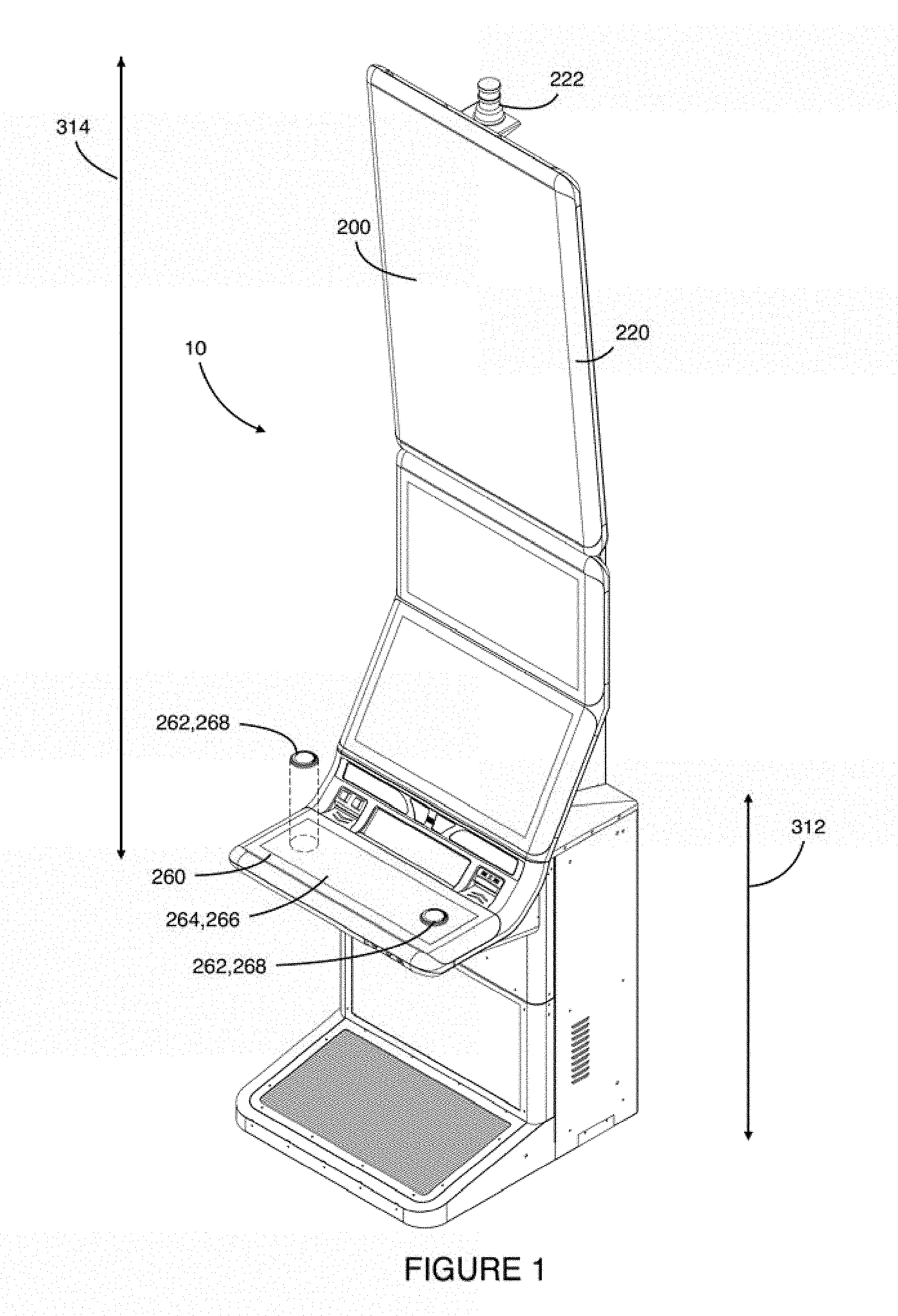
[0027] FIG. 1 is a perspective view of a wagering game machine in accordance with an embodiment;
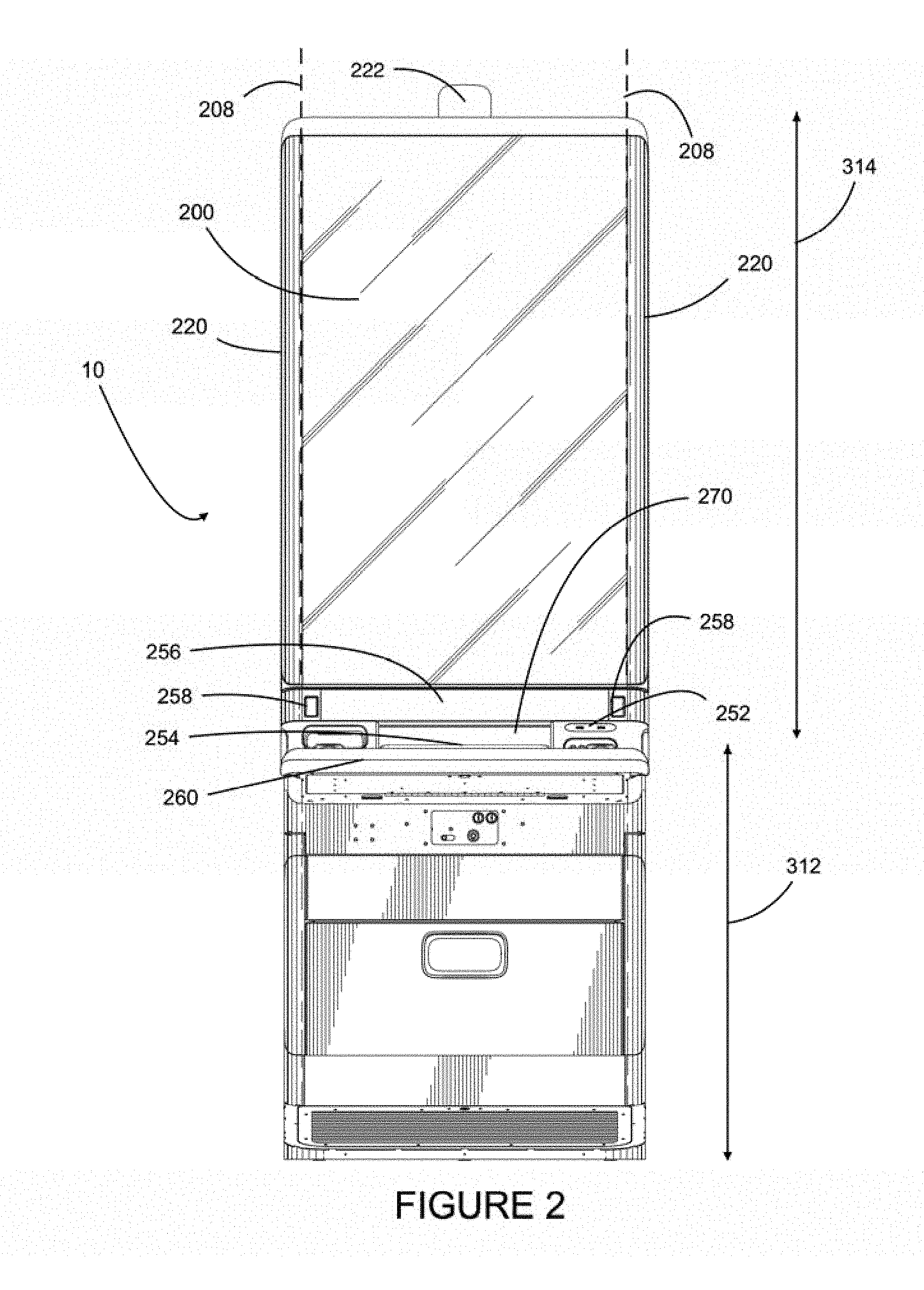
[0028] FIG. 2 is a front view of the wagering game machine of FIG. 1;
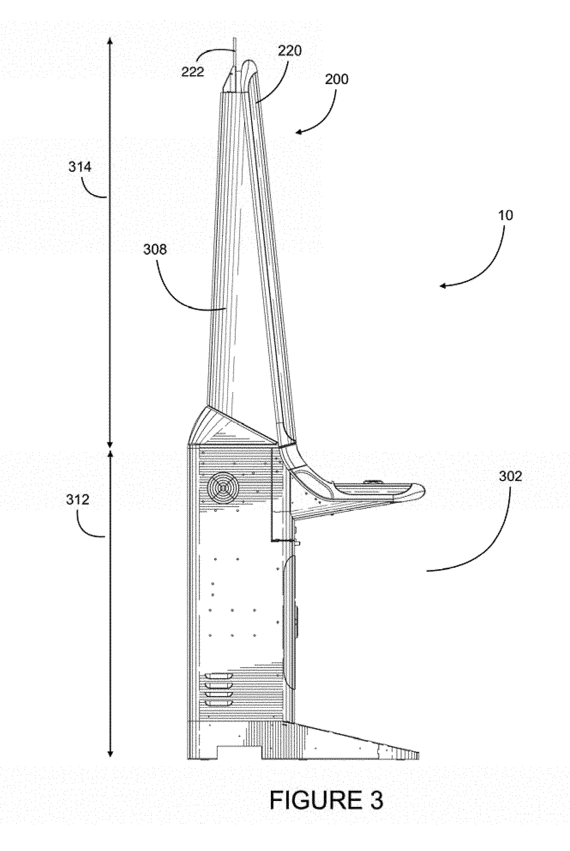
[0029] FIG. 3 is a side view of the wagering game machine of FIGS. 1 and 2;
[0030] FIG. 4 is a perspective view of a wagering game machine in accordance with another embodiment;
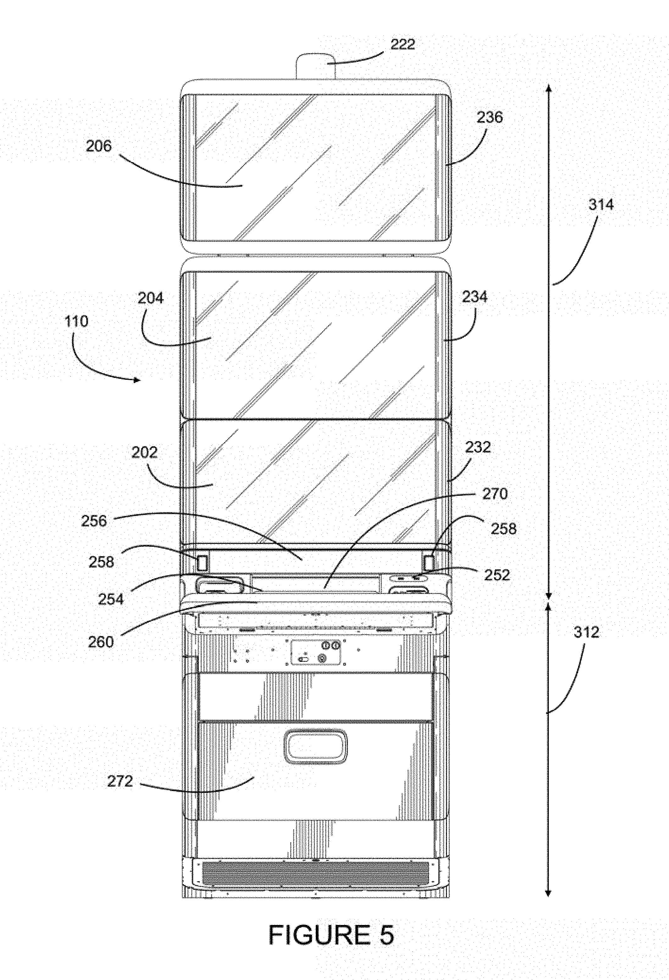
[0031] FIG. 5 is a front view of the wagering game machine of FIG. 4;
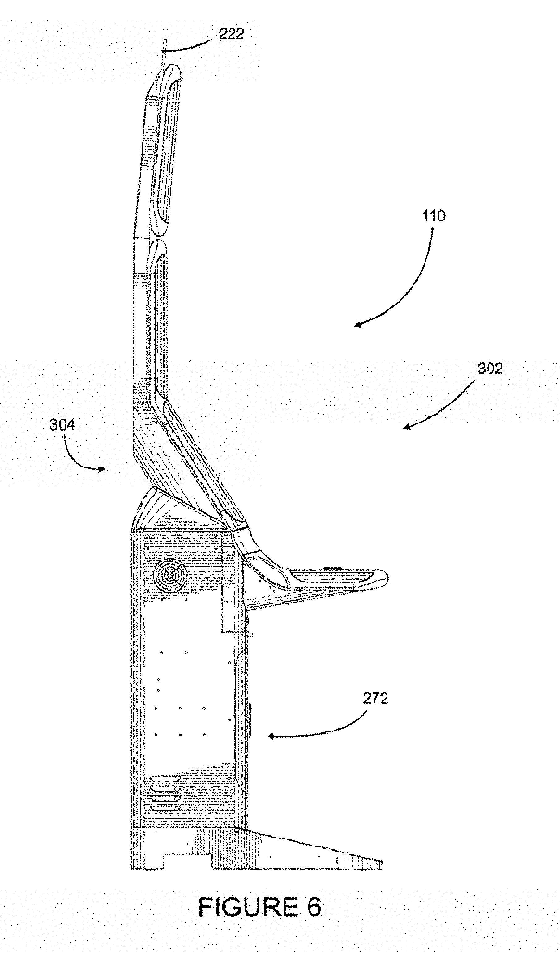
[0032] FIG. 6 is a side view of the wagering game machine of FIGS. 4 and 5;
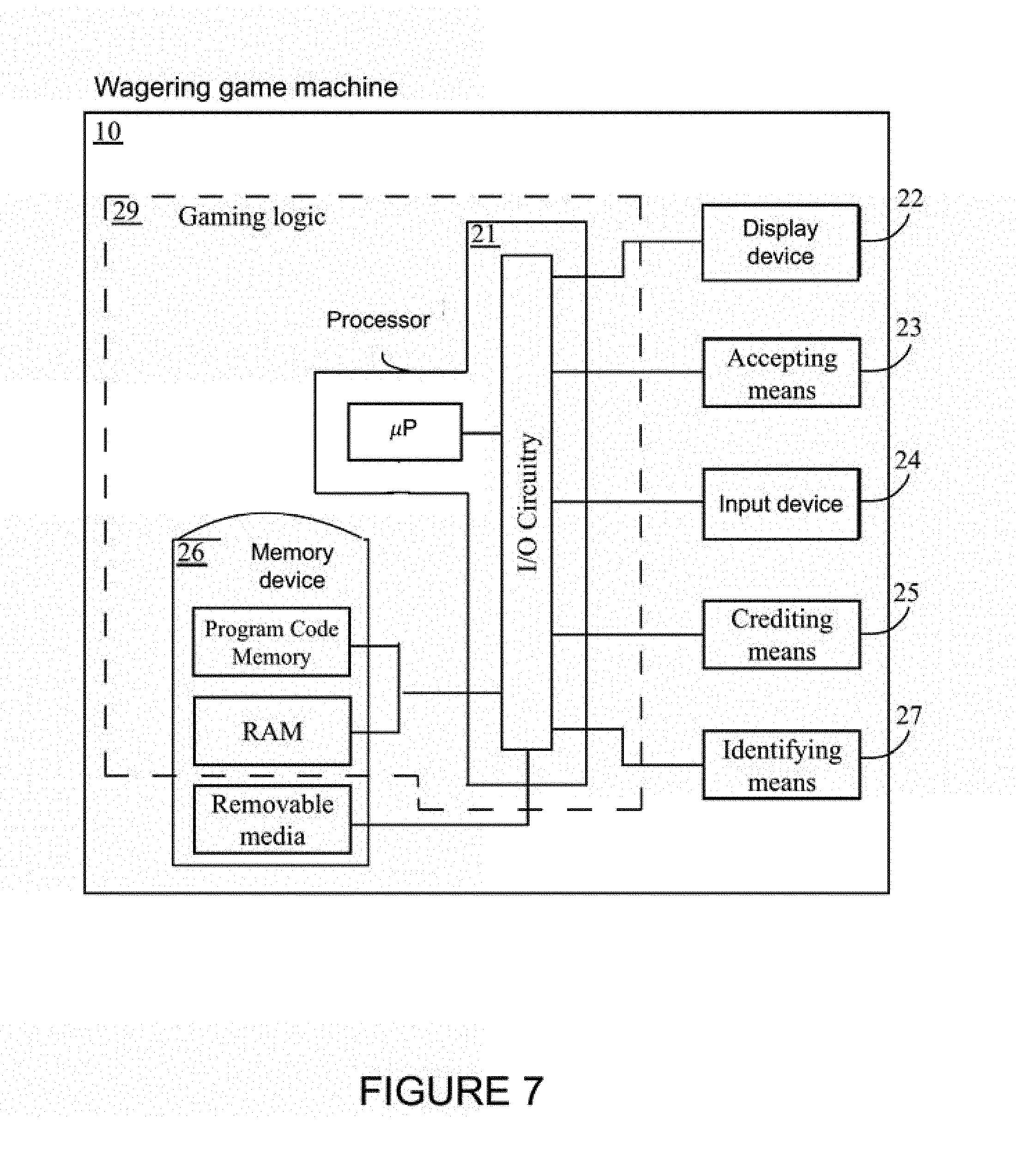
[0033] FIG. 7 is a schematic of the components of a wagering game machine in accordance with an embodiment;
[0034] FIG. 8 is a flow chart of steps performed a wagering game machine in accordance with an embodiment;
[0035] FIG. 9 is a perspective view of a control button according to an embodiment;
[0036] FIG. 10 a cross-section elevated view of the control button of FIG. 9 along the line A-A;
[0037] FIG. 11 is an exploded top perspective view of the control button of FIG. 9;
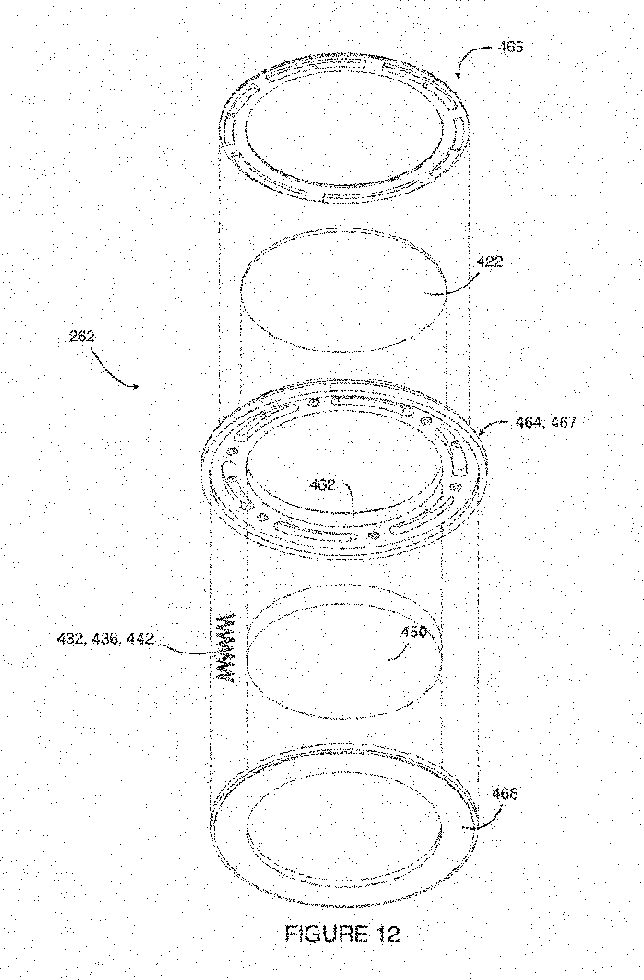
[0038] FIG. 12 is an exploded bottom perspective view of the control button of FIG. 9;
[0039] FIG. 13 is a perspective top view of a portion of the body of the control button of FIGS. 9-12; and
[0040] FIG. 14 is a perspective bottom view of the body of the control button of FIGS. 9-12.
[0041] It will be noted that throughout the appended drawings, like features are identified by like reference numerals.
DETAILED DESCRIPTION
[0042] In the present specification, the terms and expressions "gambling", "gambling activities", "gaming activities", "wagering", etc. are meant to refer to any process through which a player places a wager, and according to an outcome generation and evaluation process, a prize value is established and awarded to a player.
[0043] The terms and expressions "player" and "patron" mean a person engaged or potentially engaged in a gambling activity.
[0044] The terms and expressions "wagering game machine", "gaming machine", "game machine", "gaming terminal", "gaming device", "game device", "gaming table", "player station" etc. are meant to refer to any device adapted to perform gambling services, such that a player may be engaged in a gambling activity through that device.
[0045] The term and expressions "game" in relation with gambling activities refers to the presentation of the gambling activity to a player, or interaction in a gaming activity with one or more players. The game may be an instant game that may be resolved instantly, a multi-player game where many players are involved in the gaming activity and wherein the actions of a player may influence the outcome provided to another player, or a game featuring some similar or different characteristics that results in the game fulfilling the above gambling definition.
[0046] The terms "monetary value" mean any value exchangeable for goods and services.
[0047] The terms "medium" and "media", in relation with monetary value, are meant to encompass any physical or electronic support for monetary values.
[0048] Referring now to the drawings, and more particularly to FIGS. 1 to 6, two embodiments of wagering game machines 10, 110 are illustrated.
[0049] Referring particularly to FIGS. 1 to 3 and additionally to FIG. 7, the wagering game machine 10 comprises a gaming machine cabinet 30 having a front 302, a back 304 and sides 308. The wagering game machine 10 comprises a lower member 312 and an upper member 314. The wagering game machine 10 houses hardware components secured inside the gaming machine cabinet 30 in the lower member 312. The wagering game machine 10 also houses other hardware components, mostly to the upper member 314, well secured to the wagering game machine 10 with most of these hardware components interfacing with the environment and the player.
[0050] Referring particularly to FIG. 7, the hardware components housed by the lower member 312 comprise memory device 26 functionally connected to the processor 21, display device 22 and input device 24 both also functionally connected to the processor 21. The memory device 26 is partially part of the gaming logic 29 of the wagering game machine 10. Removable media are considered outside the game logic 29.
[0051] The processor 21 typically comprises a processing component (a.k.a. a microprocessor) and associated In/Out circuit through which signals are exchanged between the processor 21 and the functionally connected hardware components.
[0052] The memory device 26 typically comprises program code memory (e.g. hard drive, Read-Only Memory (ROM)) wherein code processable to perform the wagering game are stored. Random Access Memory (RAM) and optionally removable media are also present or temporarily present in some embodiments. Example of optional removable media is a player club card or other player identification device a hardware component functionally connected to the processor 21 is capable of reading upon insertion or use in relation with the wagering game machine 10.
[0053] To play the wagering game, the memory stores data processable as the wagering game comprising steps comprising receiving player inputs, selecting an outcome among potential outcomes and generating visuals associated with the outcome, and the processor processes the data and inputs, generates visuals and transmits the visuals to the displays and other output components to provide the game to the players.
[0054] Additional optional components frequently present on a wagering game machine 10 comprise accepting means 23, crediting means 25 and identification means 27. The accepting means 23 is for accepting monetary value from a player, that monetary value being embodied as a bank note, an accepted value-bearing token of some sort, or an electronic value transfer. The crediting means 25 is for giving back monetary values to the player, the monetary value being one or a combination of winnings from the game and credits transferred in the game from which account the player desired to perform a withdraw. Both accepting means 23 and crediting means 25 can in some embodiments be present in a plurality of forms, and as a combination (e.g. a note reader and a printer, with the note bearing information related to credit-value). The identification means 27 is for identifying the player interacting with the machine. In some embodiments, the identification means 27 is embodied as a single component embodying both reading/detecting function and displaying function. In other embodiments, the identification means 27 takes advantage of components already present in the wagering game machine 10, for example a card reader and a display. Accordingly, the latter components are possible to be embodied in a series of distinct ways based on desired realizations, these components requiring functional characteristics of player-interfacing components and specific processing. In some cases, they require being in communication with systems remote to the wagering to gaming machine 10.
[0055] Referring to FIGS. 1 to 3, the wagering to gaming machine 10 comprises a display device 22 comprising a main display 200 and an edge display 220. The main display 200 is a typically a Liquid Crystal Display (LCD display) and is mainly used to provide the game, namely the information, the animation and the outcome relative to the wagering game.
[0056] The wagering game played on the wagering game machine 10 consists in a random process through which an outcome is provided to the player in exchange of a wager. The wagering game, in order to optimize entertainment, comprises a variety of outcomes kept in a pool of outcomes, including losing outcomes and winning outcomes, and special outcomes. The outcomes are provided using animations, with the outcome being provided as a single animation or as a series of animations summing up to the selected outcome, or selected from a distinct special pool of outcomes. Some outcomes are instantaneous, requiring no interaction from the player, and some outcomes require interaction from the player, for instance the selection of icons displayed on the screen, a player input to stop an animation, a variation of a wager specific to that interaction, participation in a multi-player process, or any other decision or input a game designer would use to improve the entertainment value of the game.
[0057] In the pool of outcomes, one or more outcomes are special outcomes having special significance to the players, for instance progressives (a.k.a. progressive prizes) which are variable value outcomes having their value increasing as players participate in a game, either locally on the wagering game machine 10 or on any wagering game machine 10 of a pool of wagering game machines sharing a participation in the progressive(s). In other cases, interactive outcomes or multi-player-process triggering outcomes are considered special outcomes. These special outcomes are intended by the game designers to be one of the features that distance their wagering game from the other wagering games of a vicinity. So, the game designers need the occurrence of the special outcomes to be highlighted in some way so that patrons in the vicinity will be aware of the game and be incited to play the game.
[0058] Back to FIGS. 1 to 3, the wagering to gaming machine 10 comprises a main display 200 located at the front 302 of the wagering to gaming machine 10 and facing a player in normal conditions. On both sides of the main display 200 are the edge displays 220. The main display 200 and the edge display 220 are joining on the side of the main display 200 over the whole height of the main display 200 at a side boundary line 208. The main display 200 and the edge displays 220 abut to define a continuous surface having a pleasing effect. The edge displays 220 have a curved profile wrapping from the main display 200 to the sides 308 of the wagering game machine 10. This also participate in providing a pleasing design.
[0059] The edge displays 220 comprises lighting components 222 outwardly oriented covered by a film 224. The film 224 is made of a transparent, semi-transparent and/or light-diffusing material for the light emitted by the lighting components 222 to be visible by a patron.
[0060] Referring additionally to FIG. 8, the processor 21, upon occurrence of a special outcome, is adapted to provide signals to the lighting components 222 (see FIGS. 1 to 6), and more specifically to the lighting rows to perform lighting functions. For instance, upon occurrence of a special outcome, an animation pattern can take place on the edge displays 220 with the color of the LEDs being selected to match or complement the nature of the animation provided on the main display 200. Furthermore, an animation on the edge displays 220 also matches the animation displayed on the main display 200.
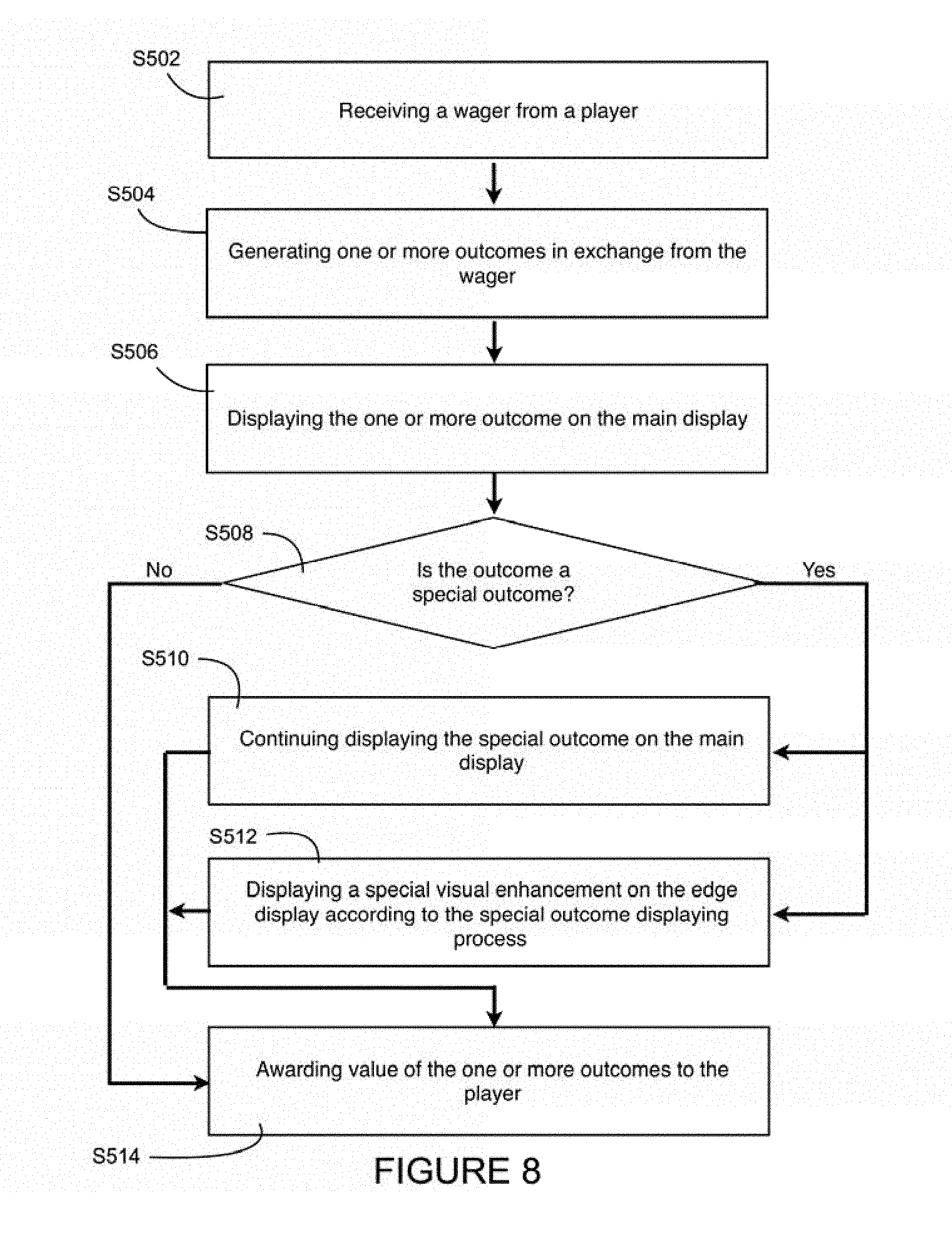
[0061] Accordingly, steps performed by the wagering game machine 10/110 can be summarized as follow:
[0062] At step S502, the step comprises receiving a wager from the player. As explained in relation with the accepting means, many forms may be available for the wager, from physical components to electronic components and data.
[0063] At step S504, the step comprises generating one or more outcomes in exchange from the wager. That step involves the withdrawal of the wager value from a player account local to the wagering game machine 10/110, and selecting an outcome to be provided to the player among a pool of outcomes. One must understand that pool of outcomes should have a broad meaning from a random selection of an element, random selection of a plurality of elements that combined together define the outcome, and/or a process of comparison of at least one random element with another comparison element to determine the outcome. Accordingly, outcomes may be instantaneous, or may involve player's participation or a plurality of players as examples.
[0064] At step S506, the step comprises displaying the one or more outcomes on the main display 200. That step usually involves displaying information and animation. In some cases, the outcome may involve a series of animations provided one after the other and summing up as the outcome. Displaying the game outcome on the main display may further comprises displaying a portion of the game interface (e.g. the outcome generation animation) on a first display component (e.g. the lower display 202, FIGS. 4-6) and displaying a second portion of the game interface, (e.g. the paytable) on a second display component (e.g. the central display 204, FIGS. 4-6). Accordingly, one should understand that the step of displaying an outcome may take many forms depending on the game, the game environment, etc.
[0065] At step S508, the step comprises evaluating if the outcome is a special outcome.
[0066] At step S510, the step comprises, in case of a special outcome, to display the special outcome on the main display 200.
[0067] At step S512 which is performed at the same time as S510, the step comprises, in case of a special outcome, to display a special visual enhancement on the edge displays 220 according to the special outcome display process.
[0068] Steps S506, S510 and S512 end with step S514. Step S514 comprises awarding the outcome value of the one or more outcomes to the player. As with step S502, step S514 may take many forms based on the components of the wagering game machine 10/110 and based on systems with which the wagering game machine 10/110 communicate.
[0069] Referring particularly to FIGS. 4 to 6, the wagering game machine 110 comprises a main display 200 comprising a plurality of distinct display components, namely a lower display 202, a central display 204 and an upper display 206 each functionally connected to the processor 21. The edge display 220 comprises also a plurality of edge display components, namely a lower edge display 232, a central edge display 234 and an upper edge display 236. The main displays (202, 204, 206) join the edge displays (232, 234, 236) along a boundary line with the joint between the side-by-side displays (202/232, 204/234, 206/236) providing a substantially continuous surface. The edge displays (232, 234, 236) wrap from the main displays (202, 204, 206) to the corresponding component of the sides 308. Each edge display (232, 234, 236) comprises a series of lighting rows (adapted relative to the length of the boundary line). Each lighting row is functionally connected to the processor 21.
[0070] Referring back to FIGS. 1 to 6, the wagering game machines 10/110 comprise a lower member 312 and an upper member 314. The wagering game machines 10/110 are designed as a modular device. The lower member 312 comprises the part of the gaming machine cabinet 30 housing the components that need to be secured out of reach of a patron. The upper member 314 is customizable to adapt to the clientele. Wagering game machines 10/110 embody examples of customization, including the size and number of displays components part of the main display 200, the configuration of the main display components, the presence, nature and configuration of additional display components such as, without limitation, edge displays, horizontal lighting components, customizable advertising components, candle light, etc. Games are designed to specific configurations, and/or processable code comprises code specific to a plurality of configurations, with the processor 21 selecting the correct code to process based either on recognition of the displays (using plug and play technology for instance) and/or based on manually entered configuration.
[0071] The lower member 312 comprises additional components, such as without limitation, overheating fans, speakers, input devices 24, lockable interior-cabinet door, and lighting components.
[0072] Connection between components housed by the upper member 314 and the lower member 312 is provided through cables passing in an enclosure located behind the main display 200 both providing structural robustness to support the main display 200 and other upper member components and proving a closed area for these cables to go through, preventing them thus to be handled by non-authorized individuals.
[0073] Joining the lower member 312 to the upper member 314 is a rear lighting wedge 240. The rear lighting wedge 240 wraps the sides 308 and the back 304 of the lower member 312 with the rear and back of the upper member 314, substantially at the base of the lowest component of the main display 200. The rear lighting wedge 240 is functionally connected to the processor 21 for control. The rear lighting wedge 240 is similar in components and configurations as the edge display 220. The lighting components of the rear lighting wedge 240 are facing substantially upward and backward to provide a lighting ambiance in the vicinity of the wagering game machine 10/110.
[0074] The rear lighting wedge 240 is further adapted to by applied on its external surface a film providing advertising on the maker of the gaming machine cabinet 30, the game designer, the game distributer, the game title and/or the vicinity in which the wagering gamine machine 10/110 is operating.
[0075] Advantages associated with the rear lighting wedge 240 comprise the emitted light providing a "floating feeling" associated with the wagering game machines 10/110, better visibility when the wagering game machines 10/110 is installed side by side with other wagering game machines in the vicinity, better perception of the thickness of the wagering game machines 10/110, and acts as cover for the physical attachments used to secure the upper member 314 to the lower member 312.
[0076] The wagering game machines 10/110 also comprise in the front 302 Universal Serial Bus ports (USB ports 252--FIGS. 2 and 5). According to a realization, the USB ports 252 are functionally connected to a power source allowing a player to recharge their phone or other personal small electronic device during a play session.
[0077] According to a realization, the USB ports 252 are functionally connected to the processor 21, capable of exchanging data with the processor 21 such as accessing Internet through the wagering game machine 10/110. According to a realization, the processor 21 is adapted to exchange data according to a specific app installed on the player's device. Accordingly, the personal device physically connected to one USB port 252, through that app, may operate as a proxy extending the playing capability of the wagering game machine 10/110, for instance by displaying animation and receiving input from the player.
[0078] According to a realization, the USB port 252 are usable for transfer secured data to the processor 21. The transfer is performed using a secured protocol and is further secured through device identification by a secured server. The transfer allows access to configuration of the wagering game machine 10/110 and/or allows download of configuration data into the wagering game machine 10/110.
[0079] The wagering game machines 10/110 further comprise a personal device rail 254 (FIGS. 2 and 5) at the rear end of a control board 260. The personal device rail 254 acts as a stand for phones and other player's personal devices. The personal device rail 254 consists of a wide upward bump appropriately located for the device to be placed on or beyond the bump leaned over the front 302 of the wagering game machine 10/110. The personal device becomes thus slightly sloped, facing front and upward relative to the wagering game machines 10/110.
[0080] The wagering game machines 10/110 further comprise a speaker bar 256 and two control buttons 258 (FIGS. 2 and 5) integrated into a horizontal feature at the top end of the lower member 312. The location and configuration provide the sound box area necessary to provide high quality sound to the player. The location of the control buttons 258, normally associated with cash-out function and service function, are ideally for easy recognition from players as to prevent accidental pushing of the buttons 258.
[0081] It must be noted that, in a preferred embodiment, the speaker bar 256 and the control buttons 258 are integrated with a contrasting color to feature visually as a horizontal stripe. The speaker grille is preferably made of metal with a small diameter continuous through hole grid.
[0082] The wagering game machines 10/110 further comprise a control panel blanking display 270 located between the rear end of the control board 260 and the speaker bar 256. The control panel blanking display 270 is for displaying information to the player provided by a remote player tracking system or an advertising system for instance. The control panel blanking display 270 is functionally connected to the processor 21.
[0083] The control panel blanking display 270, according to a realization, operates as a player tracking display, being functionally connected to a player tracking system (not shown) remote from the wagering game machine 10/110. Alternative remote systems may connect to the control panel blanking display 270 to provide a variety of experience and interactions to the player, from player tracking, membership, account management, advertising, vicinity provided rewards, etc. Functions are based on local processable data and/or functions of remote connected systems.
[0084] According to embodiments, other input/output components may also operate in relation with remote systems to feed these systems with data and provide players with information based on data received from one such remote system. Examples of other components comprise card reader, ticket reader, ticket printer, lighting system, etc.
[0085] The wagering game machines 10/110 further comprise a lighting belly glass 272 located at the front 302 under the control board 260. As other lighting components of the wagering game machine 10/110, the belly glass 272 is controlled by the processor 21 and may bear an advertising film. Lighting effects applicable on the belly glass 272 comprise, as examples, surrounding illumination, heart-beat lighting effect, gradient lighting, etc. As other display components, the belly glass 272 preferably wraps around the wagering game machine 10/110 from one side 308 to the other side 308, providing a rounded design matching the other display components of the wagering game machine 10/110.
[0086] According to embodiments, image capture or light level detection is used to monitor environment. According to algorithms, lighting components are operating in different modes based on, for instance, the presence of players in front of the wagering game machine 10/110, the darkness of the vicinity, and/or the period of the day for examples.
[0087] The wagering gaming machines 10/110 further comprise a control board 260 on which most of the controls usable by a player to play the game are located. The control board 260 is located substantially at the top of the lower member 312 of the wagering gaming machines 10/110, below the main display 200, the speaker bar 256 and the control panel blanking display 270. It extends forward, leaving leg space under, and over the width of the wagering gaming machine 10/110. Controls are mounted on its display surface 265 (see FIG. 4), providing an ergonomic configuration.
[0088] According to a realization, the controls of the control board 260 comprise a touchscreen display 266 functionally connected to the processor 21. The touchscreen display 266 is adapted with a display surface 265 to dynamically display images and to receive inputs from a player, the display surface 265 further comprising a touch sensitive component 264 reacting/responding/being activated upon contact of an electrical conducting surface (aka electrical conductor or electrical conducting element) such as the skin of a user, aka a player. The controls of the control board 260 further comprise a pair of control buttons 262 (a.k.a. press buttons or physical buttons) mounted to the display surface 265 of touchscreen display 266 and functionally connected to the processor 21 through the touchscreen display 266. The control buttons 262 are press buttons emitting a signal when pressed by a player, the signal being transmitted to the processor 21 through the touchscreen display 266. In a particular realization, the control buttons 262 are associated with play functions in the game. In some realizations, the play functions associated with the play buttons vary along the play of the game based on its current state. In a realization, the two control buttons 262 are identical in shape and function, providing an opening for player preference on the right side or on the left side of the control board 260.
[0089] The touchscreen display 266 comprises a touch sensitive component 264 extending over at least a portion of its display surface 265, the touch sensitive component 264 extending under the mounting locations of the control buttons 262 over the touchscreen display 266. According to a realization, the touch sensitive component 264 substantially extends over the whole surface of the display surface 265. The touch sensitive component 264 provides an area in which the touchscreen display 266 is sensitive to player contacts and signals from the control buttons 262. The touchscreen display 266 is adapted to emits signals to the processor 21 upon contacts from the player, for the processor 21 to potentially respond to these inputs with modification of the play of the game, image displayed on any of the main displays (202, 204, 206) and/or images to be displayed on the touchscreen display 266.
[0090] According to a realization, the touchscreen display 266 displays information and animations relative to the conduct of the game, and dynamically provides soft controls (locations on the touch sensitive component 264 sensible at that time to receive inputs from the player, not shown) and physical button display information that is visible to the player through the control buttons 262. The soft controls may be activated only at some moments of the game, or associated with specific outcomes of the game.
[0091] The control board 260, with its combination of control buttons 262 and touchscreen display 266, provides flexibility and robustness allowing an enjoyable play of the wagering game, and adaptation to different games demanding distinct display and/or distinct controls.
[0092] The processor 21 manages the touch sensitive component 264 with a mapping of coordinates corresponding to unitary areas of the touchscreen display. The processor set some of these coordinates are inactive, thus contacts over these coordinates would not result in any signal being processed. Other coordinates are set as active coordinates, among them the soft button and locations under the transparent central portion 420 of the control buttons 262 and the peripheral portion 430 (see FIGS. 9-12). The latter are halo coordinates that are managed by the processor 21 in association with two display profiles resulting in, for instance, display of different colors at these coordinates based on no signal being received in association with the control button 262 (i.e. the control buttons 262 being inactive) versus a signal being received (i.e. one of the control buttons 262 being inactive).
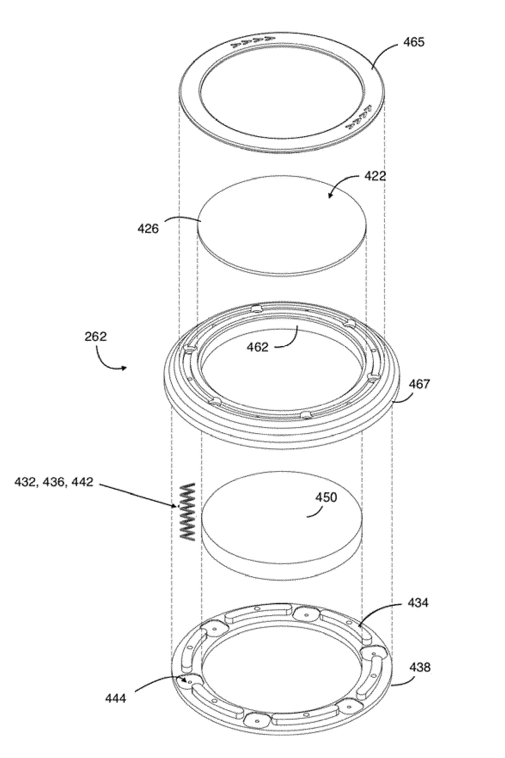
[0093] Referring additionally to FIGS. 9-12, each control buttons 262 comprises a central portion 420 and a peripheral portion 430 defining a body 410.
[0094] The central portion 420 is made of transparent material allowing a player to see through the central portion 420 images displayed by the touchscreen display 266 on which the control button 262 is mounted. The central portion 420 comprises a transparent component 422 comprising contact surface 426 on top and a touch sensitive component 424 associated therewith. According to one realization, the touch sensitive component 424 consists of a Surface Capacitive (SCAP) located distant from the contact surface 426 but reacting/responding to player contact with the contact surface 426 of the control button 262. The transparent component 422 is made of glass, and more specifically of an indium tin oxide (ITO)-type glass which is well adapted for operation characteristics associated with a gaming machine. The selection of a PCAP technology provide a longer lifespan expectancy since the contact surface 426 is less sensitive to surface scratches than alternative technologies; what is well adapted for the control button 262.
[0095] The peripheral portion 430 comprises an edge housing 438 and biasing means 432 that typically comprises a plurality of springs 442 (not illustrated at scale on FIGS. 11 and 12) housed by the edge housing 438. The biasing means 432 allows the control button 262 to pass from a default expanded configuration (aka non-conducting position) to a compressed configuration (aka conducting position) wherein the contact surface 426 of the control button 262 is lowered relatively to the expanded configuration, upon a pressure being applied over the control button 262 by the player. The peripheral portion 430 further comprises a clicking means 434, the clicking means 434 emitting a clicking sound upon the control button 262 entering its compressed configuration. The edge housing 438 further comprises electrical contacts 436 in connection on one extremity to the touch sensitive component 424 and on the other extremity to the touchscreen display 266 when the control button 262 in compressed configuration. Thus, in the conducting position, an electrical circuit is completed from the touch sensitive component 424 of the control button 262 to the touch sensitive component 264 of the touchscreen display 266 through the electrical contacts 436.
[0096] According to one realization, a common component made of transmissive material operates as the biasing means 432, the clicking means 434 and the electrical contacts 436. According to a realization, the common component comprises a series of metallic springs 442 acting also as an electrical connector 444 to the touch sensitive component 424 and an electrical interface 446 contacting the touchscreen display 266 upon the control button 262 being pressed. Upon the pression being released on the control button 262, the springs 442 push back the control button 262 in its expanded configuration, ceasing at the same time contact between the electrical interfaces 446 and the touchscreen display 266.
[0097] According to a realization, the control button 262 further comprises a lens 450 located under the transparent central portion 420, the lens 450 being for increasing the size of the image displayed by the touchscreen display 266 at the location of the control button 262 and/or visually modifying the level of the surface on which is displayed the image, displaying the image closer thus raising the image above the touchscreen display 266.
[0098] According to a realization, the control button 262 is mounted on the touchscreen display 266 using glue, another type of adhesive or another non-altering surface technique, preventing the mounting of the control button 262 on the touchscreen display 266 from negatively affecting the operation (i.e., electrical conductivity) of the touchscreen display 266 both under the control button 262 and on other portions of the touch sensitive component 264. According to realizations, the mounting material (i.e., adhesive) used is an electrically conductive material. According to a realization, the mounting material is applied over the bottom face 468 distant from the electrical contacts 436. The mounting material is further selected to be translucent, aka an optical clear adhesive, allowing light to pass through for the body 410 to be lit by the touchscreen display 266. According to realizations, the lens 450 is either freely inset in the control button 262 or mounted to the touchscreen display 266 using a similar optical clear adhesive.
[0099] According to an embodiment, the adhesive used to mount the control button 262 on the touchscreen display 266 has similar physical characteristics as those of the ITO glass used for the touchscreen display 266.
[0100] According to a realization, the edge housing 438 is of a ring shape comprising an inner face 462, an outer face 464 (comprising a top face 465 and a peripheral face 467) and a bottom face 468. The lens 450, if present, is located within the limits of the inner face 462, inset in the control button 262. According to one realization, the inner face 462 is made of an opaque material, an according to a realization of a reflective material. The outer face 464 and the bottom face 468 is at least partially made of light transmissive material. The outer face further usually has light diffusing quality. The edge housing 438 comprises light transmitting material permitting to light emitted by the touchscreen display 266 about the bottom face 468, where the control button 262 contacts the touchscreen display 266, to be transmitted to the outer face 464 to be visible by the player. According to a realization. the processor 21 responds to the reception of a signal from a control button 262 with a profile, i.e. change of colors of a halo area under the bottom face 468 from, for example, orange to green to visually confirm the player of the button press being registered.
[0101] One must note that the above description is for teaching only and the dynamic effect to be performed through the touchscreen display 266 and the control button 262 are fully customable through coding of the game.
[0102] According to a realization, the touchscreen display 266 uses a Projected Capacitive (PCAP) technology to register contacts of a player, thus the PCAP is able to register both finger contacts and electrical contacts from the control buttons 262.
[0103] The touch sensitive component 264 is further dynamically limited to an active portion defined as a subset of display addresses, wherein the limits are dynamically defined during sequences of the game. The dynamic limitation practically consists in the processor voluntary ignoring signals outside the active portion, thus outside the subset of display addresses. Thus, the player posing its finger or hand on the touchscreen display 266 outside the active portion(s) of the touch sensitive component 264 would not affect the game. One would understand that the active portion(s) of the touch sensitive component 264 comprises areas under the control buttons 262.
[0104] According to evolution of the game, the active portion(s) of the touch sensitive component 264 would be modified to comprise soft controls that would be displayed on the touchscreen display 266. The signals resulting from the activation of these soft controls would be process as distinct signals from the control button signals and would potentially be associated with different processes in the game.
[0105] According to a realization (FIG. 4), the touch sensitive component 264 extends over the width of the control board 260, having the control buttons 262 located in a button area 268 of the touch sensitive component 264. As described above, the touch sensitive component 264 features a dynamic display. According to the present embodiment, the control buttons 262 are transmitting signals upon be pressed. According to embodiments, the display in the physical button area 268 is controlled by the processor 21 to operate according to signals received from the touch sensitive component 424 associated with the control buttons 262. Thus, upon one of the control buttons 262 being pressed, what is displayed in the physical button area 268 is modified.
[0106] According to a realization, the control buttons 262 are made at least partially of transparent material or light-transmissive material. Upon being pressed, the top and/or edge surroundings of the physical button area 268 is lit up, providing a feeling that the over-mounted physical button 262 is lit up.
[0107] Referring additionally to FIGS. 13 and 14, the clicking means 434 of the control button 262 are mounted on a bottom portion of the body 410. The clicking means 434 are of a domed shape and are anchored with four legs to the bottom portion of the body 410. Upon pressure over the clicking means 434 resulting from the control button 262 passing in a compressed configuration, the dome shape of the clicking means 434 is deformed, generating the desired clicking sound. Upon the pressure being released and the control button 262 restoring to its expanded configuration. The clicking means 434 also restores to its original dome shape.
[0108] Referring particularly to FIG. 14, the six (6) springs 442 are shown to be able to pass through the bottom portion of the body 410 to contact the electric contacts 436 when the control button 262 in the compressed (aka contacting) configuration. The springs 442 and the associated passages (holes in the bottom portion and middle portion of the body 410) are sized for the springs 442 to contact the electric contacts 436 and the top portion of the body 410 when in a compressed configuration, passing through the middle and bottom portion and the body 410). The electric contacts 436 are disks of electrical conducting copper.
[0109] Still referring to FIGS. 12-14, according to another embodiment, the electrical contact is made from the central portion 420, to the springs 442, to the clicking means 434 and to the electrical contacts 436. The electrical connection is therefore made in the compressed/contacting position when the user's finger applies sufficient pressure for the clicking means 434 to contact the electrical contacts 434. As soon as pressure is release by the user, the clicking means 434 returns to its original shape and the electrical connection does not exist.
[0110] Although the description refers to a clicking means 434, this component can also be referred to as a clicker 434. The shape or configuration of clicker 434 is therefore not specifically limited to the embodiment shown in FIG. 13. Other configurations for devices which produce a clicking sound by deformation are also possible. Still according to another embodiment, the spring 442 and the clicker 434 can be combined into a single component (i.e., a clicking spring) which achieves the functions of both components.
[0111] A person of the art must note that many components of the wagering game machines 10/110 are functionally connected to the processor 21. Accordingly, in embodiments the processor 21 comprises a main processor responsible for core processes (game, credit management, remote system communication, essential input components, essential output components) while one or more add-on processors functionally connected to the main processor are responsible to control extra components (e.g. non-essential components such as belly glass 272, rear lighting wedge 240 and edge displays 220).
[0112] According to embodiments, the number of components with variable power consumption creates a challenge. Examples of variable power consumption components comprise intermittent active devices such as printers and variable power demand devices such as edge displays 220. Accordingly, hardware and/or software components are included to monitor power consumption and to limit, phase or channel power consumption to the requiring devices to prevent the power consumption to reach a power consumption threshold.
[0113] According to a realization, a power monitoring process operates in a continuous manner on the processor 21. Based on the outcome of the power monitoring, algorithms are performed to limit total power consumption. Characteristics used by the algorithms comprise device deactivation, power re-routing, and power consumption scheduling.
[0114] While preferred embodiments have been described above and illustrated in the accompanying drawings, it will be evident to those skilled in the art that modifications may be made without departing from this disclosure. Such modifications are considered as possible variants comprised in the scope of the disclosure.
* * * * *
D00000
D00001
D00002
D00003
D00004
D00005
D00006
D00007
D00008
D00009
D00010
D00011
D00012

XML
uspto.report is an independent third-party trademark research tool that is not affiliated, endorsed, or sponsored by the United States Patent and Trademark Office (USPTO) or any other governmental organization. The information provided by uspto.report is based on publicly available data at the time of writing and is intended for informational purposes only.
While we strive to provide accurate and up-to-date information, we do not guarantee the accuracy, completeness, reliability, or suitability of the information displayed on this site. The use of this site is at your own risk. Any reliance you place on such information is therefore strictly at your own risk.
All official trademark data, including owner information, should be verified by visiting the official USPTO website at www.uspto.gov. This site is not intended to replace professional legal advice and should not be used as a substitute for consulting with a legal professional who is knowledgeable about trademark law.