Time-set Accessory
HOROVITZ; MICHAEL
U.S. patent application number 15/723250 was filed with the patent office on 2019-04-04 for time-set accessory. The applicant listed for this patent is MICHAEL HOROVITZ. Invention is credited to MICHAEL HOROVITZ.
| Application Number | 20190101294 15/723250 |
| Document ID | / |
| Family ID | 65897187 |
| Filed Date | 2019-04-04 |


| United States Patent Application | 20190101294 |
| Kind Code | A1 |
| HOROVITZ; MICHAEL | April 4, 2019 |
TIME-SET ACCESSORY
Abstract
A time-set accessory, including: a knob, being shaped complementary to a lever of a gas stove, for allowing manual rotation of the lever, for selecting a dispensing extent of the gas stove; an anchor, for anchoring the body of the time-set accessory to the body of the gas stove, thereby rotation of the knob about the time-set accessory's body, rotates the lever about the gas stove's body; and a timer, for manually setting a time, and for further automatically rotating the knob about the time-set accessory's body upon termination of the time, thereby rotating the lever about the gas stove's body.
| Inventors: | HOROVITZ; MICHAEL; (BROOKLYN, NY) | ||||||||||
| Applicant: |
|
||||||||||
|---|---|---|---|---|---|---|---|---|---|---|---|
| Family ID: | 65897187 | ||||||||||
| Appl. No.: | 15/723250 | ||||||||||
| Filed: | October 3, 2017 |
| Current U.S. Class: | 1/1 |
| Current CPC Class: | F24C 3/124 20130101; F23N 5/206 20130101; F24C 3/126 20130101 |
| International Class: | F24C 3/12 20060101 F24C003/12; F23N 5/20 20060101 F23N005/20 |
Claims
1. A time-set accessory, comprising: a knob, being shaped complementary to a lever of a gas stove, for allowing manual rotation of said lever, for selecting a dispensing extent of said gas stove; an anchor, for anchoring a body of said time-set accessory to a body of said gas stove, thereby rotation of said knob about said time-set accessory's body, rotates said lever about said gas stove's body; and a timer, for manually setting a time, and for further automatically rotating said knob about said time-set accessory's body upon termination of said time, thereby rotating said lever about said gas stove's body.
2. A time-set accessory according to claim 1, further comprising: a circular spring, for applying said automatic rotation of said knob about said time-set accessory's body; and an obstacle, for allowing and disallowing said circular spring, wherein said allowing and disallowing is activated manually and by said timer.
3. A time-set accessory according to claim 1, further comprising: a plurality of depressions, each corresponding to a different rotational state of said knob; and a bolt, for allowing locking said knob to any of said depressions, thereby said automated rotation of said lever comprises automated rotation from said rotational state of said knob.
4. A time-set accessory according to claim 3, wherein said manual and automatic rotation of said knob applies, prior thereto, releasing of said locking.
Description
TECHNICAL FIELD
[0001] The invention relates to the field of timers. More particularly, the invention relates to a timer for controlling gas dispensing.
BACKGROUND
[0002] Conventional timers for cooking gas dispensers open and close a gas pipe.
[0003] However, this approach is not safe, since it interferes the gas pipes.
[0004] There is a long felt need to provide a solution to the above-mentioned and other problems of the prior art.
SUMMARY
[0005] In one aspect, the invention is directed to a time-set accessory, including: [0006] a knob; [0007] an anchor; [0008] and a timer.
BRIEF DESCRIPTION OF THE DRAWINGS
[0009] Embodiments, features, and aspects of the invention are described herein in conjunction with the following drawings:
[0010] FIG. 1 is a perspective front view of a prior art gas stove, lacking one knob.
[0011] FIG. 2 is a magnification of FIG. 1, and presenting the time-set accessory according to one embodiment of the invention.
[0012] FIG. 3 is a side sectional view of the time-set accessory of FIG. 2, being attached to the lever of FIG. 2, at the locked state.
[0013] FIG. 4 is a perspective view of the bolt and the plate of FIG. 3 at the locked state of FIG. 3.
[0014] FIG. 5 is the side sectional view of FIG. 3 at the non-locked state.
[0015] FIG. 6 is an electric circuit for triggering the electromagnet of FIG. 5.
[0016] FIG. 7 is a perspective view of the bolt and the plate of FIG. 3 at the non-locked state of FIG. 5.
[0017] FIG. 8 is a front sectional view of the time-set accessory of FIG. 2 at the closed state.
[0018] FIG. 9 is the front sectional view of FIG. 8 after the fourth step.
[0019] FIG. 10 depicts the setting of the electric timer of FIG. 6.
[0020] FIG. 11 is a side sectional view of the time-set accessory of FIG. 2, according to another embodiment, being attached to the lever of FIG. 2, at the locked state.
[0021] FIG. 12 is the side sectional view of FIG. 3 at the non-locked state.
[0022] FIG. 13 depicts the setting of the mechanical timer of FIG. 11.
[0023] FIG. 14 is a front view of the time-set accessory at the state of FIG. 13.
[0024] FIG. 15 is the front view of the time-set accessory at the end of the eighth step, and at the next steps.
[0025] The drawings are not necessarily drawn to scale.
DETAILED DESCRIPTION
[0026] The invention will be understood from the following detailed description of embodiments of the invention, which are meant to be descriptive and not limiting. For the sake of brevity, some well-known features are not described in detail.
[0027] The reference numbers have been used to point out elements in the embodiments described and illustrated herein, in order to facilitate the understanding of the invention. They are meant to be merely illustrative, and not limiting. Also, the foregoing embodiments of the invention have been described and illustrated in conjunction with systems and methods thereof, which are meant to be merely illustrative, and not limiting.
[0028] FIG. 1 is a perspective front view of a prior art gas stove, lacking one knob.
[0029] The term "gas stove" refers herein to a gas dispenser for cooking.
[0030] A prior art gas stove 62 includes several removable knobs.
[0031] FIG. 2 is a magnification of FIG. 1, and presenting the time-set accessory according to one embodiment of the invention.
[0032] A knob 68C is being removed, thus exposing the rotational operating lever 40, and a time-set accessory 10 is being placed on lever 40 instead of knob 68C.
[0033] FIG. 3 is a side sectional view of the time-set accessory of FIG. 2, being attached to the lever of FIG. 2, at the locked state.
[0034] Time-set accessory 10 is being attached to lever 40. Gas time 10 includes a knob 42, being rotatable in relation to the body 70, for rotating lever 40 in relation to gas stove 62 of FIG. 2.
[0035] A magnet or another anchor 20 anchors body 70 to the front board 72 (enumerated in FIG. 2) of gas stove 62, such that rotation of knob 42 in relation to body 70 rotates lever 40, together with a plate 16 fixed thereto, in relation to front board 72.
[0036] However, a linear spring 32 normally presses a bolt 34 or another obstacle to the left as shown by an arrow 36.
[0037] FIG. 4 is a perspective view of the bolt and the plate of FIG. 3 at the locked state of FIG. 3.
[0038] Linear spring 32 normally presses bolt 34 to the left into a depression 24A of plate 16, thus does not allow rotation of plate 16, and of lever 40, as shown by a disallowed arrow 90.
[0039] Knob 42 includes a depression 64 being shaped complementary to lever 40.
[0040] FIG. 5 is the side sectional view of FIG. 3 at the non-locked state.
[0041] An electromagnet 18 may retract bolt 34 to the right, as shown by arrow 38, against the mechanical force of linear spring 32.
[0042] Electromagnet 18 may be triggered either manually by a user-operable switch 44, or automatically by an electric timer 26A.
[0043] FIG. 6 is an electric circuit for triggering the electromagnet of FIG. 5.
[0044] Electromagnet 18 may be triggered either manually by user-operable switch 44, or automatically by a switch 82 of electric timer 26A, since user-operable switch 44 and switch 82 are disposed in parallel. However, both of switches 44 and 82 are normally open, as shown by springs 84A and 84B.
[0045] Thus, referring to FIG. 3, electromagnet 18 normally is not triggered, thus normally linear spring 32 normally presses bolt 34 to the left into depression 24A, thus does not allow rotation of plate 16, and of lever 40.
[0046] FIG. 7 is a perspective view of the bolt and the plate of FIG. 3 at the non-locked state of FIG. 5.
[0047] Triggering of electromagnet 18 removes bolt 34 from depression 24A.
[0048] Prior art gas stove 62 is characterized in that the rotational state of lever 40 is which adjusts the intensity of the cooking.
[0049] Since the rotation of plate 16 by knob 42 rotates lever 40, and since bolt 34 is not rotational, the intensity of the cooking is a function of which depression of plate 16 is currently disposed against bolt 34.
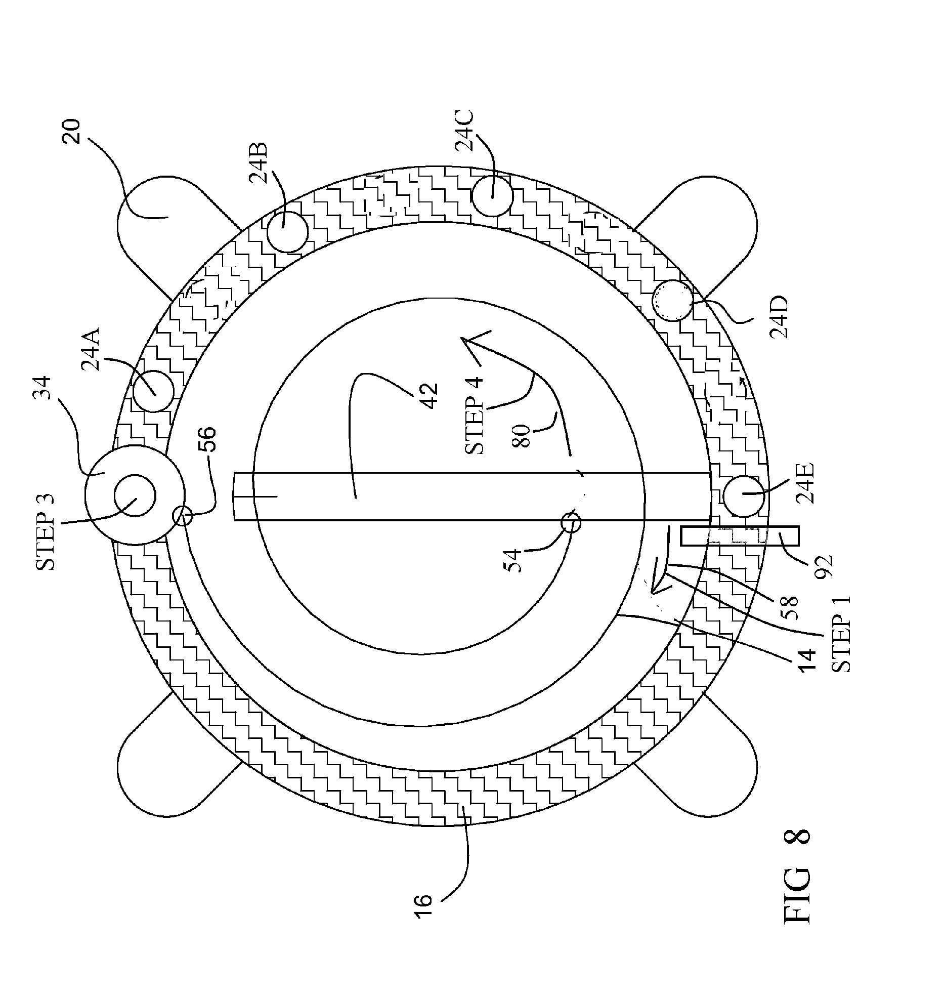
[0050] FIG. 8 is a front sectional view of the time-set accessory of FIG. 2 at the closed state.
[0051] At the first step, and referring to FIG. 8, being the normal initialization state, a circular spring (mainspring) 14, shown also in FIG. 5, tends to rotate plate 16 together with knob 42 and lever 40 along direction 58 towards the gas non-dispensing state, until a barrier 92, being stationary in relation to body 70 of FIG. 3, does not allow further rotation of knob 42 in relation to body 70.
[0052] At this state, and referring again to FIG. 3, linear spring 32 presses bolt 34, thus bolt 34 does not allow the user to rotate plate 16 together with knob 42 and lever 40, since bolt 34 might enter any of depressions 24A, 24B, etc., lever 40 locks the gas dispensing to the non-dispensing state.
[0053] At the second step, and referring again to FIG. 6, the user manually closes user-operable switch 44.
[0054] At the third step, being induced by the second step, and referring again to FIG. 5, bolt 34 is retracted (to the right in the figure) by electromagnet 18 against linear spring 32.
[0055] The retraction of bolt 34 allows the user, as shown in FIG. 7, to rotate plate 16 together with knob 42 and lever 40, since bolt 34 does not enter any of depressions 24A, 24B, etc.
[0056] At the fourth step, and referring again to FIG. 8, the user may rotate plate 16 together with knob 42 and lever 40 in direction 80, against circular spring 14, to a desired gas intensity state.
[0057] FIG. 9 is the front sectional view of FIG. 8 after the fourth step.
[0058] Since the user has rotated plate 16 and knob 42 against circular spring 14, circular spring 14 is more tense in FIG. 9. According to the example of FIG. 9, the user has selected the gas intensity state in which bolt 34 is disposed against depression 24D.
[0059] At the fifth step, and referring again to FIG. 6, the user opens user-operable switch 44 to cancel the electromagnetic force.
[0060] At the sixth step, being induced by the fifth step, and referring again to FIG. 3, linear spring 32 presses bolt 34, to enter depression 24D, thereby locking the rotational state of plate 16 together with knob 42 and lever 40, thereby locking the gas dispensing to the selected gas intensity.
[0061] FIG. 10 depicts the setting of the electric timer of FIG. 6.
[0062] At the seventh step, the user may select a time 86, for which switch 82 of FIG. 6 remains open.
[0063] At the eighth step, and referring again to FIG. 6, electric timer 26A automatically closes switch 82, thus triggers electromagnet 18.
[0064] At the ninth step, being induced by the eighth step, and referring again to FIG. 5, bolt 34 is retracted (to the right in the figure) by electromagnet 18 against linear spring 32.
[0065] At the tenth step, being induced by the ninth step, and referring yet to FIG. 5, circular spring 14 rotates plate 16 together with knob 42 and lever 40 from the selected gas intensity state of FIG. 9, back to the non-dispensing state of FIG. 8.
[0066] FIG. 11 is a side sectional view of the time-set accessory of FIG. 2, according to another embodiment, being attached to the lever of FIG. 2, at the locked state.
[0067] According to this embodiment, electric timer 26A of FIG. 3, may be replaced by a mechanical timer 26B, as described following.
[0068] Time-set accessory 10 is being attached to lever 40, and includes knob 42, being rotatable in relation to body 70, for rotating lever 40 in relation to gas stove 62 of FIG. 2.
[0069] A linear spring 32 normally presses bolt 34, through a toggle 60 to the left as shown by an arrow 36.
[0070] FIG. 12 is the side sectional view of FIG. 3 at the non-locked state.
[0071] Instead of electromagnet 18 of FIG. 5, a linear spring 30, being stronger than linear spring 32, may retract bolt 34, through toggle 60, to the right, as shown by arrow 38, against the mechanical force of linear spring 32.
[0072] Linear spring 30 may be active by disposing a rod 98 against a hole 74, either manually, or automatically by mechanical timer 26B. Once linear spring 30 is inactive, linear spring 32 presses bolt 34 to the left into depression 24A, thus does not allow rotation of plate 16, and of lever 40.
[0073] At the first step, and referring to FIG. 8, being the normal initialization state, circular spring 14 tends to rotate plate 16 together with knob 42 and lever 40 along direction 58 towards the gas non-dispensing state, until barrier 92, being stationary in relation to body 70 of FIG. 11, does not allow further rotation of knob 42 in relation to body 70.
[0074] At this state, and referring again to FIG. 11, linear spring 32 presses bolt 34, thus bolt 34 does not allow the user to rotate plate 16 together with knob 42 and lever 40, since bolt 34 might enter any of depressions 24A, 24B, etc., lever 40 locks the gas dispensing to the non-dispensing state.
[0075] At the second step, and referring to FIG. 12, the user inserts rod 98 into hole 74.
[0076] At the third step, being induced by the second step, and referring yet to FIG. 12, bolt 34 is retracted (to the right in the figure) by spring 30 against linear spring 32.
[0077] The retraction of bolt 34 allows the user, as shown in FIG. 7, to rotate plate 16 together with knob 42 and lever 40, since bolt 34 does not enter any of depressions 24A, 24B, etc.
[0078] At the fourth step, and referring again to FIG. 8, the user may rotate plate 16 together with knob 42 and lever 40 in direction 80, against circular spring 14, to a desired gas intensity state.
[0079] According to the example of FIG. 9, the user has selected the gas intensity state in which bolt 34 is disposed against depression 24D.
[0080] At the fifth step, and referring again to FIG. 11, the user pulls rod 98 out of hole 74 to cancel the force of spring 30 on toggle 60.
[0081] At the sixth step, being induced by the fifth step, and referring yet to FIG. 11, linear spring 32 presses bolt 34, to enter depression 24D, thereby locking the rotational state of plate 16 together with knob 42 and lever 40, thereby locking the gas dispensing to the selected gas intensity of FIG. 9.
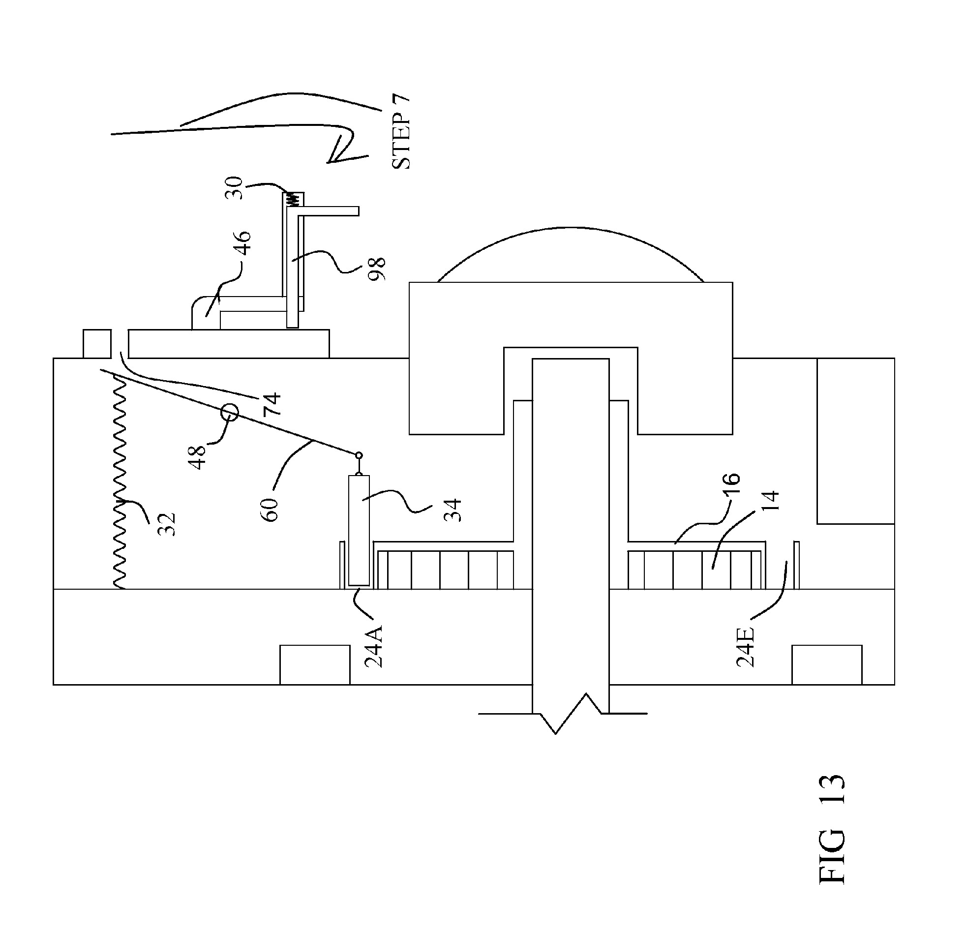
[0082] FIG. 13 depicts the setting of the mechanical timer of FIG. 11.
[0083] At the seventh step, the user may rotate rod 98 about an axle 46, for not allowing rod 34 to enter hole 74.
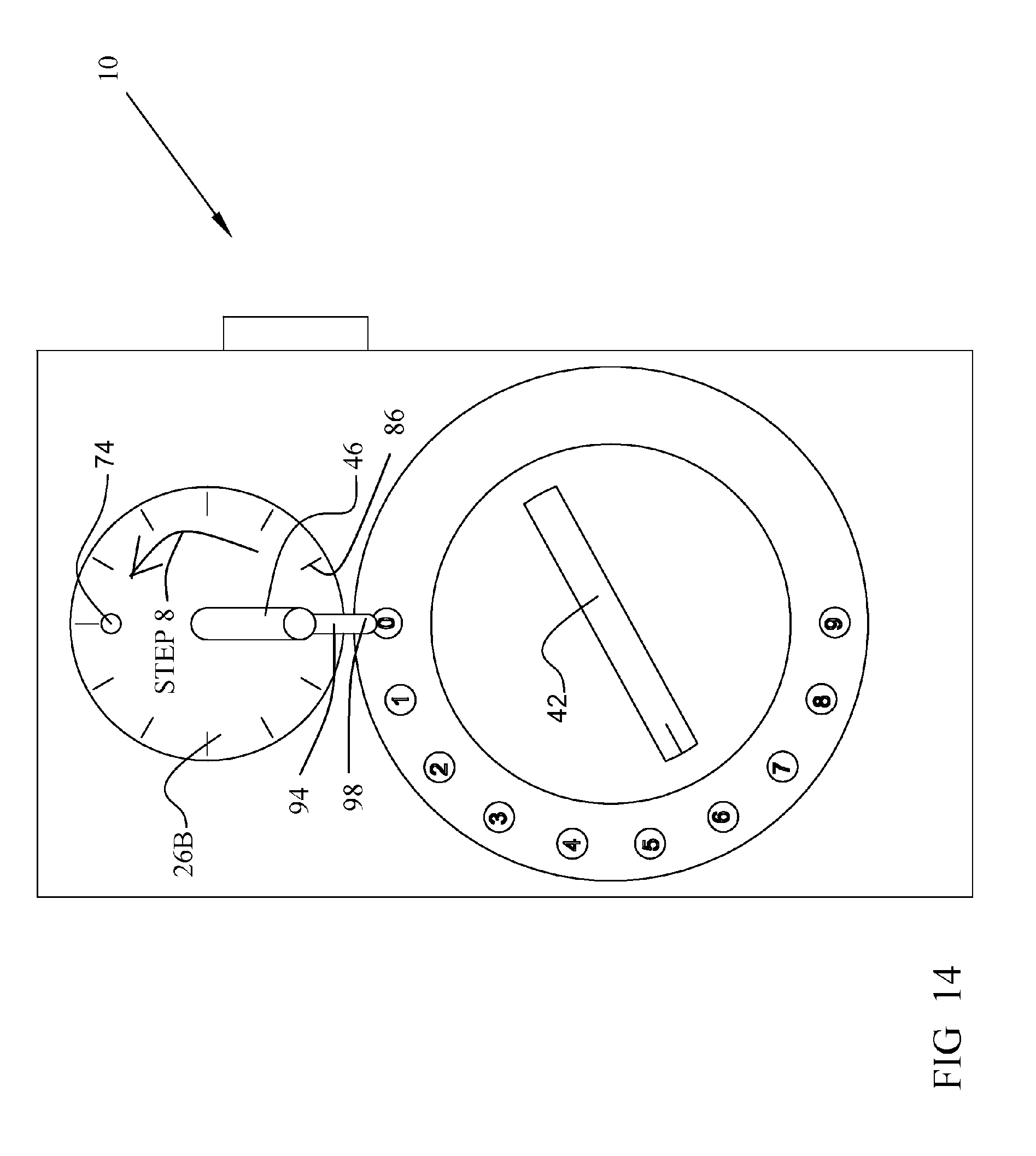
[0084] FIG. 14 is a front view of the time-set accessory at the state of FIG. 13.
[0085] The rotation of rod 34 about axle 46 further selects a time 86, for which spring 30 cannot press toggle 60 of FIG. 13.
[0086] At the eighth step, mechanical timer 26B rotates rod 34 about axle 46 towards hole 74.
[0087] FIG. 15 is the front view of the time-set accessory at the end of the eighth step, and at the next steps.
[0088] At the end of the eighth step, being after the set time, rod 34 enters hole 74.
[0089] At the ninth step, being induced by the eighth step, and referring again to FIG. 12, bolt 34 is retracted (to the right in the figure), through toggle 60 by spring 30 against linear spring 32.
[0090] At the tenth step, being induced by the ninth step, and referring yet to FIG. 12, circular spring 14 rotates plate 16 together with knob 42 and lever 40 from the selected gas intensity state of FIG. 9, shown also in FIG. 14, back to the non-dispensing state of FIG. 8, shown also in FIG. 15.
[0091] Thus, in one aspect, the invention is directed to a time-set accessory (10), including: [0092] a knob (42), being shaped complementary (64) to a lever (40) of a gas stove (62), for allowing manual rotation of the lever (40), for selecting a dispensing extent of the gas stove (62); [0093] an anchor (20), for anchoring the body (70) of the time-set accessory (10) to the body (72) of the gas stove (62), thereby rotation of the knob (42) about the time-set accessory's body (70), rotates the lever (40) about the gas stove's body (72); and [0094] a timer (26A, 26B), for manually setting a time (86), and for further automatically rotating the knob (42) about the time-set accessory's body (70) upon termination of the time (86), thereby rotating the lever (40) about the gas stove's body (72).
[0095] The time-set accessory (10) may further include: [0096] a circular spring (14), for applying the automatic rotation of the knob (42) about the time-set accessory's body (70); and [0097] an obstacle (34), for allowing and disallowing (90) the circular spring (14), wherein the allowing and disallowing is activated manually and by the timer (26A, 26B).
[0098] The time-set accessory (10) may further include: [0099] a plurality of depressions (24A, 24B), each corresponding to a different rotational state of the knob (42); and [0100] a bolt (34), for allowing locking the knob (42) to any of the depressions (24A, 24B), thereby the automated rotation of the lever (40) constitutes automated rotation from the rotational state of the knob (42), being from a gas intensity selected by the user, to turning the gas to off.
[0101] The manual and automatic rotation of the knob (42) applies, prior thereto, releasing of the locking.
[0102] In the figures and/or description herein, the following reference numerals (Reference Signs List) have been mentioned: [0103] numeral 10 denotes the time-set accessory according to one embodiment of the invention; [0104] numeral 14 denotes a mainspring or circular spring; [0105] numeral 16 denotes a plate; [0106] numeral 18 denotes an electromagnet; [0107] numeral 20 denotes fixing means or any anchor; [0108] numerals 24A, 24B, 24C, 24D and 24E denote depressions; [0109] numeral 26A denotes the electric timer; [0110] numeral 26B denotes the mechanical timer; [0111] numeral 30 denotes a spring; [0112] numeral 32 denotes a spring; [0113] numeral 34 denotes a movable bolt or another obstacle; [0114] numerals 36 and 38 denote arrows; [0115] numeral 40 denotes a rotational lever of a prior art gas stove; [0116] numeral 42 denotes a knob; [0117] numeral 44 denotes a user-operable switch; [0118] numeral 46 denotes the axle of the mechanical timer; [0119] numeral 48 denotes a hinge for rotating the toggle, for inverting the linear motion from side to side thereof; [0120] numerals 54 and 56 denote holding points of the circular spring, one to the body and the other to the knob, thus the circular spring rotates the knob in relation to the body; [0121] numeral 58 denotes a rotational direction; [0122] numeral 60 denotes a toggle; [0123] numeral 62 denotes the prior art gas stove; [0124] numeral 64 denotes a depression; [0125] numerals 68A, 68B and 68C denote prior art knobs; [0126] numeral 70 denotes the time-set accessory's body; [0127] numeral 72 denotes the gas stove body; [0128] numeral 74 denotes a hole; [0129] numeral 72 denotes the body of the gas stove; [0130] numeral 76 denotes an electric power source; [0131] numeral 80 denotes a rotational direction; [0132] numeral 82 denotes an electric switch; [0133] numerals 84A and 84B denote springs; [0134] numeral 86 denotes a time, set by the user; [0135] numeral 88 denotes an electric wire; [0136] numeral 90 denotes a disallowed rotation; [0137] numeral 92 denotes a barrier; [0138] numeral 94 denotes a handle; [0139] numeral 98 denotes a rod, extending from the handle;
[0140] The foregoing description and illustrations of the embodiments of the invention have been presented for the purpose of illustration, and are not intended to be exhaustive or to limit the invention to the above description in any form.
[0141] Any term that has been defined above and used in the claims, should to be interpreted according to this definition.
[0142] The reference numbers in the claims are not a part of the claims, but rather used for facilitating the reading thereof. These reference numbers should not be interpreted as limiting the claims in any form.
* * * * *
D00000
D00001
D00002
D00003
D00004
D00005
D00006
D00007
D00008
D00009
D00010
XML
uspto.report is an independent third-party trademark research tool that is not affiliated, endorsed, or sponsored by the United States Patent and Trademark Office (USPTO) or any other governmental organization. The information provided by uspto.report is based on publicly available data at the time of writing and is intended for informational purposes only.
While we strive to provide accurate and up-to-date information, we do not guarantee the accuracy, completeness, reliability, or suitability of the information displayed on this site. The use of this site is at your own risk. Any reliance you place on such information is therefore strictly at your own risk.
All official trademark data, including owner information, should be verified by visiting the official USPTO website at www.uspto.gov. This site is not intended to replace professional legal advice and should not be used as a substitute for consulting with a legal professional who is knowledgeable about trademark law.