Systems And Methods For Providing A Knitting Needle
Decker; Cynthia ; et al.
U.S. patent application number 16/116793 was filed with the patent office on 2019-04-04 for systems and methods for providing a knitting needle. The applicant listed for this patent is Jonathan Bronson, Cynthia Decker, Ann Fairbourn. Invention is credited to Jonathan Bronson, Cynthia Decker, Ann Fairbourn.
| Application Number | 20190100862 16/116793 |
| Document ID | / |
| Family ID | 65526064 |
| Filed Date | 2019-04-04 |


View All Diagrams
| United States Patent Application | 20190100862 |
| Kind Code | A1 |
| Decker; Cynthia ; et al. | April 4, 2019 |
SYSTEMS AND METHODS FOR PROVIDING A KNITTING NEEDLE
Abstract
Some implementations of the described invention relate to a knitting needle. While this first knitting needle can have any suitable characteristic or component, in some cases, it defines a groove that extends longitudinally along a length of the knitting needle. In some cases, the groove opens near a point end (or distal end) of the first needle. Thus, in some cases, a tip of a second knitting needle can run through the groove, such that the tip of the second needle is able to readily pass under a portion of yarn (or other material) that is on the first knitting needle. In some cases, a proximal end of the knitting needle comprises an object that is wider than a width of a shaft of the needle. In some cases, the described knitting needle is coupled with another needle via a non-resilient coupler. Other implementations are described.
| Inventors: | Decker; Cynthia; (South Jordan, UT) ; Fairbourn; Ann; (South Jordan, UT) ; Bronson; Jonathan; (South Jordan, UT) | ||||||||||
| Applicant: |
|
||||||||||
|---|---|---|---|---|---|---|---|---|---|---|---|
| Family ID: | 65526064 | ||||||||||
| Appl. No.: | 16/116793 | ||||||||||
| Filed: | August 29, 2018 |
Related U.S. Patent Documents
| Application Number | Filing Date | Patent Number | ||
|---|---|---|---|---|
| 62551996 | Aug 30, 2017 | |||
| Current U.S. Class: | 1/1 |
| Current CPC Class: | D04B 15/68 20130101; D04B 15/02 20130101; D04B 35/02 20130101; D04B 3/02 20130101 |
| International Class: | D04B 3/02 20060101 D04B003/02; D04B 35/02 20060101 D04B035/02; D04B 15/02 20060101 D04B015/02 |
Claims
1. A knitting apparatus, comprising: a first knitting needle, wherein the first knitting needle defines a first groove extending along a portion of a length of the first knitting needle.
2. The apparatus of claim 1, wherein the first knitting needle comprises an elongated shaft, wherein the elongated shaft comprises a substantially flat exterior surface, and wherein the first groove is defined in the substantially flat exterior surface.
3. The apparatus of claim 1, wherein the first knitting needle comprises an elongated shaft, wherein a portion of the elongated shaft comprises a polygonal shape, wherein a first surface of the polygonal shape defines the first groove, and wherein a second surface of the polygonal shape defines a second groove that extends along the portion of the length of the first knitting needle.
4. The apparatus of claim 1, wherein the first knitting needle comprises an elongated, square shaped shaft, wherein the first groove is defined in a first face of the square shaped shaft, and wherein a second, third, and fourth groove are respectively defined in a second, third, and fourth face of the elongated, square shaped shaft.
5. The apparatus of claim 1, wherein the first knitting needle further comprises: a distal end having a pointed tip; and a proximal end comprising an object that is wider than a width of an elongated shaft of the first knitting needle.
6. The apparatus of claim 1, further comprising a second knitting needle, wherein the second knitting needle defines a second groove extending along a portion of a length of the second knitting needle, wherein the first and second knitting needles are coupled together with a flexible coupler.
7. The apparatus of claim 6, wherein the flexible coupler has comprises a non-resilient material.
8. A knitting system comprising, a first knitting needle comprising an elongated shaft having: a distal end comprising a pointed tip of the first knitting needle; a proximal end; and a first groove defined in an exterior surface of the elongated shaft, wherein the first groove extends from a distal portion of the elongated shaft, proximally along a length of the elongated shaft, and wherein the first groove is configured to receive a pointed tip of a second knitting needle.
9. The system of claim 8, wherein the first groove is longer than about 2 cm.
10. The system of claim 8, wherein the elongated shaft defines a second groove that extends from the distal portion of the elongated shaft, proximally along the length of the elongated shaft.
11. The system of claim 8, wherein: the elongated shaft comprises a four-sided shaft, the first groove is defined in a first side of the four-sided shaft, and a second, third, and fourth groove are respectively defined in a second, third, and fourth side of the four-sided shaft.
17. The system of claim 8, further comprising the second knitting needle, and wherein the first knitting needle comprises a first distinguishing feature that readily distinguishes the first knitting needle from the second knitting needle.
13. The apparatus of claim 8, further comprising the second knitting needle, wherein the proximal end of the first knitting needle and a proximal end of the second knitting needle are coupled together via a non-resilient coupler.
14. The apparatus of claim 8, wherein the first groove opens at its distal end to allow the pointed tip of the second knitting needle to slide distally out of the first groove.
15. A knitting system comprising: a first knitting needle comprising a four-sided, elongated shaft having: a proximal end; a pointed distal end; and a first, second, third, and fourth groove, that each extend from a distal portion, and longitudinally along a length, of the four-sided, elongated shaft, with the first, second, third, and fourth groove respectively being defined in a first, second, third, and fourth face of the four-sided, elongated shaft.
16. The system of claim 15, further comprising a second knitting needle, wherein the proximal end of the first knitting needle and a proximal end of the second knitting needle are coupled together via a non-resilient coupler.
17. The system of claim 16, wherein the first knitting needle comprises a first distinguishing feature that readily distinguishes the first knitting needle from the second knitting needle.
18. The system of claim 16, wherein the first knitting needle comprises a first dominant color, and wherein the second knitting needle comprises a second dominant color that is readily distinguishable from the first dominant color.
19. The system of claim 15, wherein the first groove opens at its distal end to allow a pointed tip of a second knitting needle to slide distally through and out of the first groove.
20. The system of claim 15, wherein the proximal end of the first knitting needle an object that is wider than a width of four-sided, elongated shaft of the first knitting needle.
Description
RELATED APPLICATIONS
[0001] This application claims priority to U.S. Provisional Patent Application Ser. No. 62/551,996, filed Aug. 30, 2017, and entitled SYSTEMS AND METHODS FOR PROVIDING A KNITTING NEEDLE (Attorney Docket No. 27210.2), which is incorporated herein in its entirety by reference.
FIELD
[0002] Some implementations of the described invention relate to a knitting needle. While this knitting needle can have any suitable characteristic or component, in some cases, it defines a groove that extends along at least a portion of a length (or a longitudinal axis) of the knitting needle. In some cases, the groove opens near a point end of the first needle. Thus, in some cases, a point of a second knitting needle can run through a groove in a first knitting needle, allowing the point of the second needle to pass under a portion of yarn (or other material) that is on the first knitting needle.
BACKGROUND
[0003] There are a variety of material choices for knitting needles. A knitter may choose the size, length, and shape of a needle. Additionally, knitters may choose a set of needles that are pointed at both ends, which (when worked together) may be used to knit small circular projects.
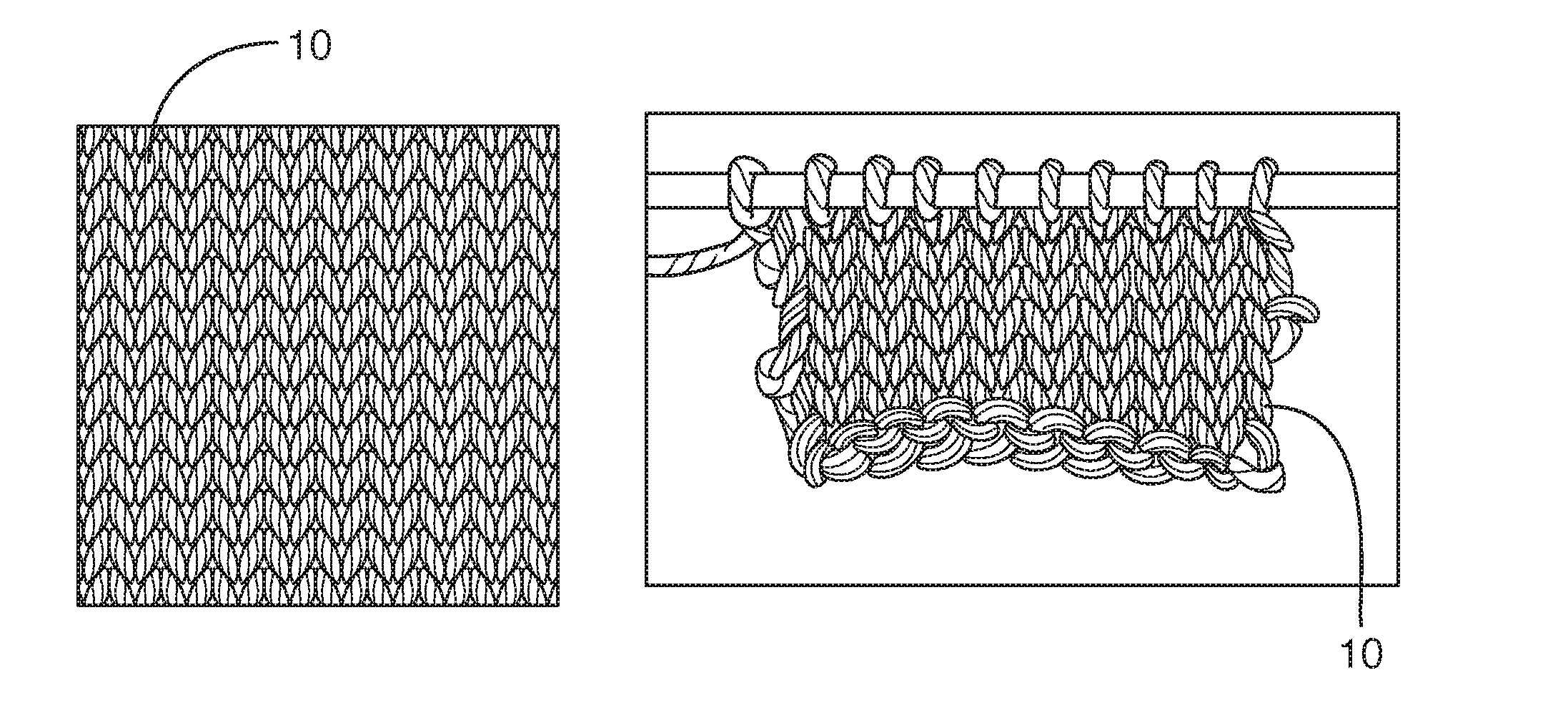
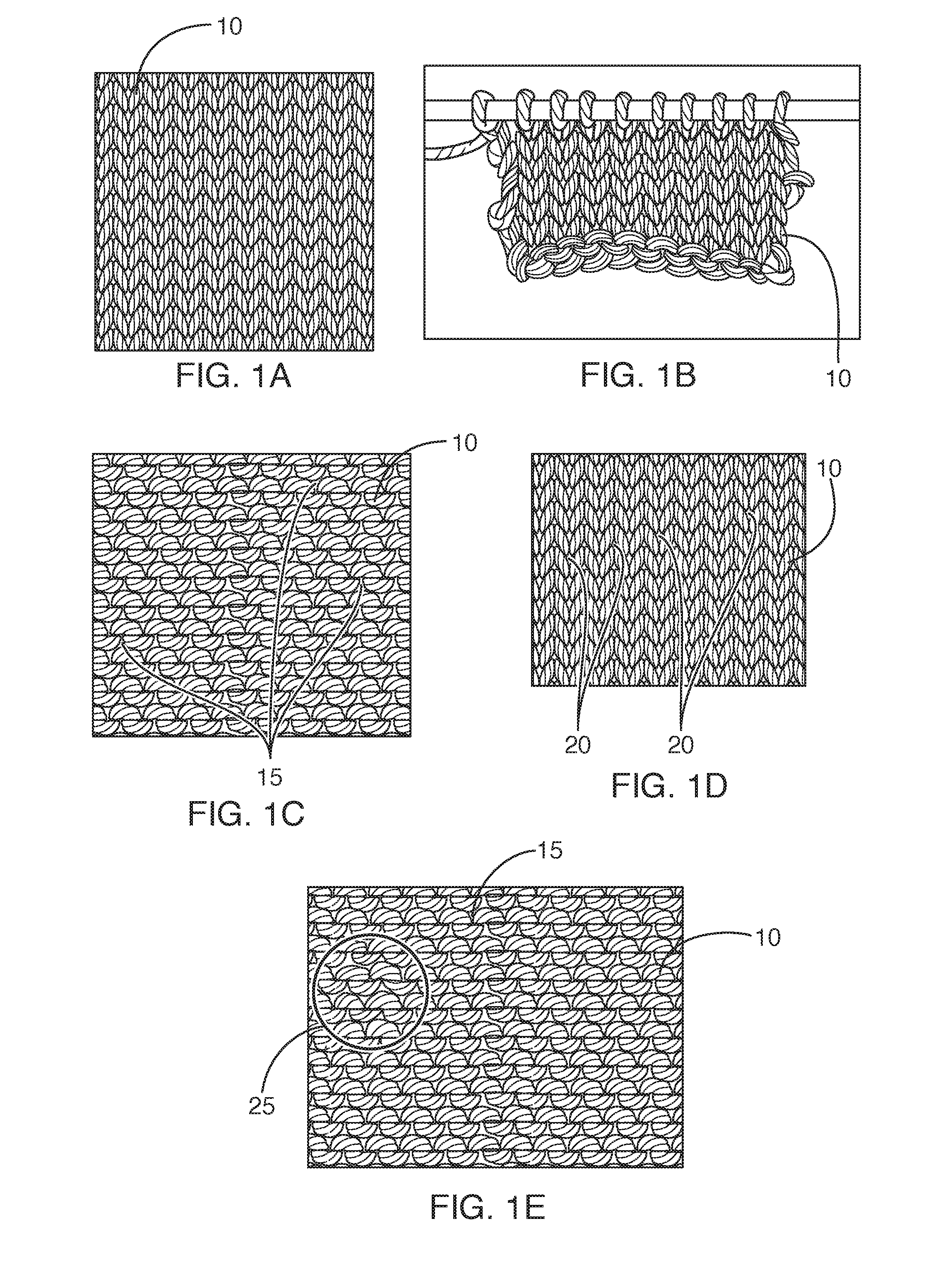
[0004] Unfortunately, the explosion of knitting needle choices has not solved some of the biggest problems reported by knitters, both old and young. As one example of such a problem a problem which frustrates experienced knitters and keeps some new knitters from continuing it can be difficult to create even tension consistently. In this regard, the term even tension (and variations thereof) may refer to a knitting process (or a knitted material) in which each stitch or loop receives substantially the same amount of yam. An example of a knitted material 10 having stitches with substantially even tension is shown in FIG. 1A.
[0005] One possible problem with many conventional knitting techniques is that of uneven tension. Some instances of uneven tension include, but are not limited to: oversized stitches that look like gaps or holes in the knitted material 10 (see e.g., FIG. 1B) next to small tight stitches in the same row, guttering 15 between rows (or larger than normal spaces between rows visible on the back side of the knitted material) (see e.g., FIG. 1C), rowing out (or rows of stitches that stand out on the front side of the knitted material) (see e.g., FIG. 1D), puckering of stitches due to yarn splitting 25 (see e.g., FIG. 1E), having a piece of knitting that changes from tight to loose over a length of the project, having finished projects that either take much more or much less yarn than what is suggested by a pattern, having a failed project that does not fit as intended, and having a knitted stockinette pattern (or one row of knit stitches followed by one row of purl stitches, repeated) that rolls or curls violently from either the sides or the bottom.
[0006] Tension problems are often so ubiquitous that over the years many tricks or methods have been passed around hoping to mitigate such problems. Some examples of such methods include the following techniques that were taken from several popular knitting blogs: 1) Never knit the stockinette pattern. Instead, choose a similar pattern that disguises the difference in tension between the knit stitch and the purl stitch. 2) Never purl or purl backwards. 3) Always knit in the round. 4) Pick yarns to hide any flaws. 5) Teach your hands to adjust, specifically to loosen whichever stitch is tight and/or tighten whichever stitch is loose. 6) Use different sized needles, one for knit stitches and one for purl stitches. (Many knitters, when knitting a stockinette pattern resort to adding a ribbed border in order to force the stockinette pattern to lay flat rather than t roll up. This roll is the result of uneven tension between garter stitches and purl stitches). In the end, each of these proposed methods has its limitations, and none of them is a perfect solution.
[0007] Currently, tension (which should generally be applied to the yarn when knitting) is often managed by a knitter's hands. This tension helps to: 1) keep the yarn in position in order to form a stitch, 2) hold the yarn around the needle as the next stitch is created, 3) determine the size of each stitch, and/or 4) provide other necessary assistance to a knitter. While controlling tension can be important, it can also be useful to vary the tension of the yarn slightly as the knitter knits,
[0008] There are a myriad of ways for a knitter to hold and tension the yarn. Some common methods usually involve bringing the new yarn from its source to the palm, up between the fingers at a point next to the palm, and wrapping the yarn around one of the fingers, and finally ending up on the top of the first finger. In this regard, the first finger is used to direct the yarn onto the needle. The purpose of this "winding" around the fingers is to put tension on the yarn.
[0009] As a general rule, there are at least two basic stitches when knitting: the knit stitch and the purl stitch. The knit stitch begins at a front of the loop and the purl stitch begins at a back of the loop. A stitch is created when the knitter slides the working needle (in the right (or dominant) hand, in some cases) under the right (or other) leg and through the center of the stitch or loop on the resting needle (in the left hand (or recessive hand, in some such cases)) then wraps new working yarn (from the ball of yarn) around the point of the working needle and finally brings that yarn back under the stitch or loop, thereby creating a new stitch that is then transferred to the working needle. In some cases, knitters report a difference in the length of yarn used between a knit stitch and a purl stitch. In some cases, knitters also disagree over which stitch is tighter and which stitch is looser, and to be fair, the difference may lie in the hands of each specific knitter. Tensioning the yarn is often considered to be the number one skill required to create an evenly knitted fabric. In some cases, minor changes in how the yarn is held and apportioned while knitting can lead to major disruptions in tension. Additionally, there are other forces at work which can also lead to uneven tension.
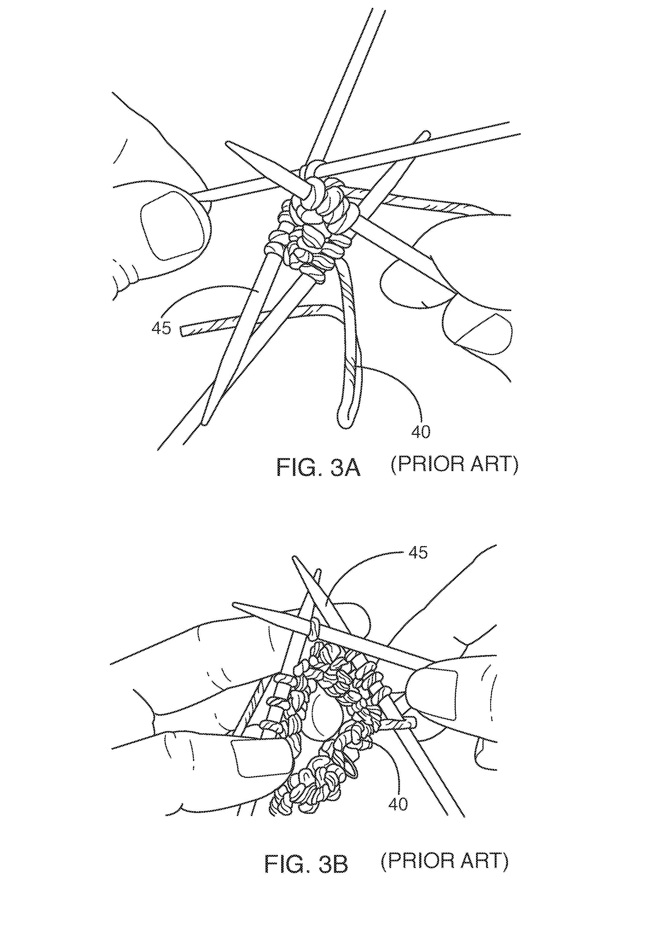
[0010] As another problem, some conventional methods for knitting are prone to allow yarn splitting. In this regard, if the knitter, when trying to slide the working needle 30 under the right (or another) leg and through the center of the stitch or loop on a resting needle 35, accidently pierces and goes through the yarn on the resting needle, the yarn 40 is split or a yarn splitting 25 occurs (see e.g., FIGS. 2A-2B). Part of the yarn will be knitted into the new stitch and part of the yarn remains behind on the resting needle, which will eventually be caught up in the next stitch. The yarn is thus locked into two different stitches, which tightens them both and disrupts the tension. This accident is common and cannot be blamed completely on the knitter. The knitter, in order to be successful in some cases, may need to bring the point of the working needle snugly against the resting needle and while maintaining contact, slide it under the right leg of the loop and through the center of the stitch. Another significant problem common among many of today's knitters is the inability to easily knit projects having small circumferences, such as are found in many small hats, small sleeves, socks, and gloves, etc. A variety of methods have been developed to overcome this difficulty with limited success. Today there are knitters who still use a set of small double pointed needles or DPNs 45 (usually 3 or 4 resting needles plus one working needle), overlapping end to end in order to knit a piece having a small circumference (see e.g., FIG. 3A).
[0011] In some such cases, the first resting needle, having been freed from all of its loops by the first working needle becomes the next working needle and travels to the next resting needle which, when freed from all of its loops by the second working needle, becomes the new working needle. This process of leap-frogging around the circumference continues around and around the piece, each resting needle becoming the new working needle in its turn. There are often three problems with this method. 1) If the knitter is using three resting needles and one working needle and each needle has two pointy ends there are a total of eight pointy ends to contend with. In this case "contend with" means keeping the yarn from dropping off of eight pointy ends while the knitter is adding stitches. 2) When a knitter begins and ends the stitches on a working needle it is common for the first and last stitch to be slightly larger than the stitches in the middle of the working needle. Unless pulled very tight and held firmly until the next stitch is locked in place there will be gaps or stitches that are too large between each set of needles on the knitted piece. 3) This method of creating a small circumference is often slow and awkward work (see e.g., FIG. 3B). Often, when the pattern changes, new struggles come into play as the knitter attempts to add or decrease stitches in a tight, point filled area. For many projects there comes a point when the circumference, which began very small, has been enlarged enough that the knitter transfers the work to a conventional circular knitting needle system to finish the project. When transferring the project from the double pointed needles to the circular knitting needle system, the opportunity to drop stitches looms large. Dropped stitches take time and effort to pick up correctly. Few problems are more frustrating.
[0012] Thus, while systems and methods currently exist that are used for knitting, challenges still exist, including those listed above. Accordingly, it would be an improvement in the art to augment or even replace current techniques with improved tools and techniques.
SUMMARY OF THE INVENTION
[0013] Some implementations of the described invention relate to a knitting needle. While this knitting needle can have any suitable characteristic or component, in some cases, it defines a groove that extends longitudinally along a length of an outer surface of the knitting needle. In some cases, the groove opens near a pointed end (or a distal end) of the described needle. Thus, in some cases, a tip of a second knitting needle can run longitudinally through the groove, such that the tip of the second needle is able to readily pass under a portion of yarn (or other material) that is on the described grooved knitting needle. In some cases, a proximal end of the described knitting needle comprises an object that is wider than a width of a shaft of the needle so as to prevent yard loops from falling off of the proximal end of the needle. In some cases, the described knitting needle is coupled with another needle. While such coupling can be achieved in any suitable manner, in some cases, the two needles are coupled together with a non-resilient coupler. Additionally, in some instances in which the grooved knitting needle is used with a second needle (whether or not the two needles are coupled together), at least one of the needles comprises a distinguishing feature that allows the two needles to be readily distinguished. For instance, the two knitting needles can be different colors.
[0014] The described knitting needles (referred to herein in some cases as grooved needle(s)) are knitting needles for the 21.sup.st century and beyond. In many cases, they incorporate a beautiful design and use basic science to solve tension problems. Indeed, rather than fight with the knitter, the described grooved needles are configured to help the knitter to create a beautiful evenly knitted fabric--and, in some implementations, they do it no matter how big or how small the circumference of the project, without having to change from one system to another.
[0015] The described grooved needles can be any suitable shape (e.g., have an elongated shaft with a cross-section taken perpendicularly to a longitudinal axis of the needle that is substantially square, triangular, pentagonal, hexagonal, round, cylindrical, circular, elliptical, star-shaped, multi-pointed, multi-protrusion, multi-cornered, multi-edged, symmetrical, asymmetrical, polygonal, regular shaped, irregularly shaped, and/or any other suitable shape). In some implementations, the described grooved needles comprise square knitting needles (or needles having a shaft with a square cross-sectional view) which in some implementations comprise: a slot, a recess, a space between two or more ridges or processes, a depression, a concavity, and/or other groove on or in the face of one or more sides and/or external surfaces of the needle (e.g., on four sides of a square needle).
[0016] In accordance with some implementations, the described grooved needles define a right angle groove, a V-shaped groove, a U-shaped groove, a dove-tail shaped groove (e.g., having a relatively narrow opening that broadens towards a base of the groove), a rounded groove, and/or any other suitably shaped groove (or needle guide) that is defined in (or otherwise incorporated. into) the needle. Indeed, in some cases, a V-shaped groove is cut, milled, molded, ground, etched, printed, and/or otherwise formed in the face of one or more sides, faces, or even corners (e.g., at four sides) of the needle, with the groove having an angle between about 60 degrees and about 5 degrees, or any subrange thereof (e.g., about 45 degrees.+-.30 degrees).
[0017] While the depth of the groove can be any suitable depth, in some implementations, the depth of each groove is between about 1/10 and about 9/10 of the total depth (or thickness) of the shaft of the needle, or any subrange thereof (e.g., about 1/4 of the total depth of the needle). In some implementations of a 9 inch (228.60 mm) or a grooved needle comprising a straight knitting needle of any other suitable length, one of more of the grooves begins and/or opens between about 0.001 mm and about 50 mm, or any subrange thereof (e.g., about 11.37 mm) from the described needle's distal tip (or point) and continues between about 5 mm and about 300 mm, or any subrange thereof (e.g., about 75.95 mm) toward the proximal end of the needle before ending. Thus, in some implementations, a tip of a second needle can be placed in the groove of a first needle (e.g., below a piece of yard wrapped around the first needle) and the second needle can slide distally through the groove and then be released form a distal end of the groove.
[0018] In some implementations, the distal tip of the described needle transitions or tapers from the grooved concave section to a round, curved, squared, pyramidal, pointed, and/or other suitably shaped point which is any suitable size (e.g., having a width or diameter between about 0.1 mm and about 1 cm or any subrange thereof, such as about 5 mm) and then is radius-ed (or otherwise shaped) to any suitable size (e.g., between about 0.01 mm and about 20 mm or any subrange thereof, such as about 0.25 mm).
[0019] In some cases, the proximal end of the needle is optionally fitted, formed with, and/or otherwise comprises a square cube, a cross bar, and/or an object of any other suitable shape which is any suitable size (e.g., between about 1.1 and about 10 times, or any subrange thereof), such as about two times) larger than the width of the needle shaft. In some implementations, one or more (e.g., all) edges of the square cube (or other shaped object or enlargement at the needle's proximal end) are radius-ed to between about 0.1 mm and about 1 cm, or any subrange thereof (e.g., to about 0.25 mm.+-.5 mm). In some cases, this cube (or other suitable object) acts as a stop to the yarn, ensuring that yarn will not drop off of the proximal end of the needle. In any case, the described needles, and their various features, can be manufactured to be any suitable size.
[0020] The described needles can also comprise any suitable material, including, without limitation, one or more types of wood, bamboo, metal, metal alloy, nylon, plastics, polymers, carbon fibers, acrylics, glass, synthetic materials, natural materials, ceramics, combinations thereof, and/or other suitable materials.
[0021] In some cases, tension is improved when using a square (or other cornered) needle shaft because kinetic friction of the yarn over the corners of the needle retards the movement of the yarn, essentially creating a bobbin case-like tensioner, automatically regulating the amount of yarn sliding around the needle with very little fluctuation. The magnitude of the force depends on the coefficient of kinetic friction between the yarn and the needle. In some cases, it is possible to calculate the force of kinetic friction for any combination of yarn and needles, but it should suffice to say that this force exists and exerts an influence on the movement of yarn around the square needle. Some might argue that yarn being pulled around a circular needle has the same kinetic friction. It can be true, there can be kinetic friction between the yarn and a circular needle, but (in some cases) is generally not the same amount of friction. Since the areas of actual contact on the square needle are often relatively small (typically the 90 degree corners of a square needle hold the yarn slightly above the four faces of the square), the pressures at the points of contact (the corners) can be relatively high. In some cases, a square needle or needle having a shaft with a cross section having four points) creates more friction between the yarn and the needle than a round needle may. Almost anyone who has ever pulled a rope around both a square post and a circular post will recognize that the rope around the square post has more tension. In accordance with some implementations, the slight retarding of the thread or yarn around the square needle helps the knitter regulate tension automatically, mechanically, and evenly with little fluctuation.
[0022] But kinetic friction is only part of the equation in the quest for even tension. Human error, exacerbated by an inadequate knitting system is often the reason a square needle alone is not enough to guarantee good tension. This is where the "gully," depression, recess, slot, guide, furrow, trench, indentation, and/or other groove comes in. Because there is a groove in one or more faces (e.g., 1, 2, 3, 4, 5, 6, 7, or more), corners, or surfaces of the shaft of some implementations of the described needle, the knitter can utilize the groove to slide the tip (or distal point) of the working needle into the groove, under the right leg of the yarn (as applicable) and through the center of the stitch on the resting needle with ease, capture the new working yarn and then slide back the same way it went in, taking the captured yarn with it. Boucle, textured, heirloom, novelty, and/or any other similar yarns are no longer to be feared because some implementations of the described groove have made room for them, With some implementations of the described grooved needles, it is no longer difficult to hold the tip of the working needle snuggly against the shaft of the resting needle because the tip will be held inside the groove on a lower plane than the loops of yarn. The tip of the working needle can travel inside this groove under the loops of yarn. Thus, in accordance with some implementations, the chance of splitting the stitch has been significantly reduced and the opportunity for even tension has been significantly increased.
[0023] Often a knitter, when decreasing the stitches on the working needle, needs to knit two or three stitches together, (k2tog or k3tog) and bring them all, at the same time, under the right (or another applicable) leg of the yarn and through the center (or another appropriate portion) of the stitch on the resting needle. This can be difficult, even for an experienced knitter. But when the knitter utilizes the described groove to slip the combined stitches back under and through the center of the stitch, the task becomes much easier.
[0024] Another way that the described grooved needles (e.g., needles having one or more grooves and being triangular, square, U-shaped, V-shaped, and/or any other suitable shape) work to control tension is this: as the needle is turned, the knitter can readily see the needle (and grooves) twist and/or roll. In this regard, most, if not all, needles roll in the hands of the knitter. When a needle rolls during the formation of a stitch, the needle pulls the yarn with it in the direction of the roll, making the stitches slightly bigger and/or slightly smaller depending on the direction of the roll. When the needle rolls and how much the needle rolls depends in part on the knitter and in part on the needle and in part on the yarn. This roll can be hard to recognize when using some round needles because the landscape of a round needle does not necessarily change as it rolls or twists. But with a grooved needle (as discussed herein), a knitter can see the change as the needle rolls and control the roll to his or her benefit.
[0025] Some implementations of the described grooved needles include a circular knitting needle system, or a system that comprises a pair of needles that are coupled together (in the case of the described system, the term circular may simply connote two grooved needles coupled together and not require that the system form or comprise any circle). Indeed, in some implementations, the described circular knitting system includes a pair of relatively short (e.g., between 1 inch and about 14 inches, or any subrange thereof, such as about 4 inches or about 114.31 mm), square (or any other suitably shaped) needles that are coupled together and which, in some implementations, are given a relatively slight concavity on one or more faces (e.g., each face) of the sides of the needles. In accordance with some implementations, a resilient coupler; a non-resilient coupler; a smoothly woven, flexible cord, strap, cloth or other object that comprises nylon, cloth, a strap, leather, fabric, and/or any other suitable material connects the two needles together. In some such cases, the needles are used for knitting projects which involve very small circumferences as well as knitting flat panels or working in the round. While such needles can comprise any suitable material, in some implementations, the needles comprise one or more hardwoods, bamboos, metals, nylons, ceramics, polymers, synthetic materials, natural materials, plastics, glasses, acrylics, carbon fibers, and/or any suitable materials. In accordance with some implementations, the needles have a deep, right angle (and/or any other suitable angled, rounded, curved, and/or other suitably shaped) groove that is cut, molded, ground, etched, and/or otherwise formed into the middle (and/or other suitable surface) of one or more sides (e.g., each of the sides of the needles) at about any suitable angle, including, without limitation, at an angle between about 5 degrees and about 110 degrees, or within any subrange thereof (e.g., about a 45 degree angle). In some cases, the depth of the groove equals between about 1/10 and about 9/10 , or any subrange thereof (e.g., about of the total depth (or thickness) of the needle's shaft, though the groove can have any other suitable depth. In some cases, one or more grooves begin between about 0.001 mm and about 50 mm, or any subrange thereof (e.g., at about 11.69 mm) from the needle's distal tip and continue between about 1 mm and about 300 mm, or any subrange thereof (e.g., about another 31.57 mm) toward the proximal end of the needle before ending.
[0026] In some instances, the distal tip of the needle transitions or tapers from the grooved concave section to a point which is between about 0.1 mm and about 20 mm, or any subrange thereof (e.g., about 5 mm) in width or diameter, in some cases, the point (or tip) is also radius-ed to any suitable size, including, without limitation, to between about 0.01 mm and about 1 cm, or any subrange thereof (e.g., about 0.25 mm). In some cases, the needles are also made in sizes comparable to any or all US and European sizes. Additionally, in some non-limiting implementations, the grooves remain proportionately constant to the size of the needle.
[0027] In some cases, the flexible cord (and/or other connector), which is attached to the proximal ends of each needle (e.g., via gluing, an adhesive, a threaded coupling mechanism, a clamping mechanism, a friction fit mechanism, one or more fasteners, one or more catches, via a weld, one or more clips, and/or in any other suitable manner), is made of a smoothly woven, nylon, and/or other suitable type of cord or material (e.g., parachute cord, string, ribbon, and/or any other suitable cord). Additionally, although some implementations of this coupling mechanism or coupler are at least somewhat resilient or biased towards a certain position, some other implementations of the coupler have little or absolutely no bias or spherical, circular, semi-circular, bent, and/or curved memory (e.g., the coupler comprises a non-resilient material).
[0028] Additionally, the coupler can be attached to the needles at any suitable time and in any suitable manner. For instance, in the case of some plastic (or other suitable) needles, the coupler is fused into the described needles at the time of molding, additive printing, and/or other formation. In the case of some wooden (and other types of) needles, the smoothly woven, flexible, nylon cord (and/or any other suitable connecting mechanism, coupler, or connector) is attached with a glue-in method into a prepared void in the proximal ends of each needle. In the case of some metal (and other types of) needles, the smoothly woven, nylon cord (and/or other suitable connecting mechanism) is attached with a clip-in method or similar method which includes a swivel into a spherical (and/or other suitably shaped) void prepared for the cord in the proximal end of each needle. The cord may be of any suitable length. In some cases, the knitting is held on the smoothly woven, flexible nylon cord (or other coupler) between the two needles without fear of dropping any stitches.
[0029] Using some implementations of the described grooved needle comprising a circular knitting system (or circulars), a knitter is able to close the pin-hole at the smallest point of a circumference of a knitted work without changing to the clumsy DPNs. Because, in accordance with some implementations, the smoothly woven, flexible, nylon cord (and/or another suitable connector) has little or even absolutely no bias or spherical memory it does not impede or get in the way of the knitter. Indeed, in some implementations, the cord (or other coupler) does not exert any undue force on the stitches, does not pull the stitches out of shape and can bend over onto itself or be pinched together without the threat of breakage or permanent kinking. Additionally, in some implementations, the smoothly woven, flexible nylon cord (or other coupler) does readily twist and/or roll when the knitting needle rolls, which can be a very useful characteristic.
[0030] The smoothly woven, flexible, nylon cord (and/or other suitable connection mechanism) of the described circular knitting system is also used, in some implementations, to detect needle rolling and/or twisting. Indeed, in accordance with some implementations, when a needle rolls and/or twists, the cord will also twist if it is flexible enough (most often the twist happens with the working needle.) This occurs frequently at the beginning of a knitted piece when there are few stitches/loops in place. The twisting of the smoothly woven, flexible cord (or other suitable connector) can be readily recognized (e.g., as the cord twists, binds, a pattern on the coupler twists, and/or the coupler otherwise twists) and can act as a barometer, of sorts, of the kind of knitting being produced by the knitter. Without this barometer, some knitters may not understand what is happening and why the tension is inferior. When a knitter sees the cord (or coupler) twist, for example, a simple roll of the needle in the opposite direction can bring the needle into the correct position in order to avoid over or undersized loops/stitches. And if the knitter has created a loop or stitch that is oversized or undersized, in some cases, a simple twist of the needle executed while either entering or exiting the stitch or loop will take extra yarn out of a loop or put extra yarn into the loop. The ability to pull yarn into or out of a loop is made possible, in some implementations, because of the four corners of the square needle (or the corner or corners of any other suitably shaped needle) and their ability to retard and control the movement of yarn.
[0031] In some implementations, the described grooved needles hold the yarn in place so that there is little or no "loosening" as one knits the next stitch. This ability of the described grooved needle to hold the yarn in place on the knitting needle can reduce the need to fix the stitch by drawing extra yarn out of the loop. In some cases, it also decreases the need to hold or "trap" the yarn on the needle.
[0032] The combination of the needle (e.g., the square and/or other suitable shaped needle) and the groove on the face of one or more of the surfaces of the described needles (e.g., on each of the four faces of a square needle) work together, in some implementations, to automatically and consistently control tension and greatly reduce the chance for human error. Indeed, in accordance with some implementations, straight grooved needles and circular grooved knitting needles give the knitter, whether old or young, experienced or novice, the optimal environment for even tension.
[0033] In accordance with some implementations, where two grooved knitting needles are used together (either when coupled together or when used without any coupling), the two needles can comprise one or more features that allow the needles to be readily distinguished. In this regard, some examples of such distinguishing features include, but are not limited to, one of the needles comprising a different color, shape, marking, identifier, and/or other characteristic than the other needle. Indeed, in some implementations, the two needles each comprise a different dominant color. For instance, while one needle is red, the other needle can be grey. In any case, where the two needles are readily distinguishable, such a feature can serve any suitable purpose. By way of example, by having readily distinguishable needles, a knitter can easily remember which needle is the working needle.
[0034] In accordance with some implementations, the described grooved needles are configured to be used to knit flat panels to create sweaters, cowls, shawls, scarves, blankets, hats, stockinettes, socks, gloves, jackets, and/or any other suitable articles.
[0035] These and other features and advantages of the present invention will be set forth or will become more fully apparent in the description that follows and in the appended claims. The features and advantages may be realized and obtained by means of the instruments and combinations particularly pointed out in the appended claims. Furthermore, the features and advantages of the invention may be learned by the practice of the invention or will be obvious from the description, as set forth hereinafter.
BRIEF DESCRIPTION OF THE DRAWINGS
[0036] In order that the manner in which the above recited and other features and advantages of the present invention are obtained, a more particular description of the invention will be rendered by reference to specific embodiments thereof, which are illustrated in the appended drawings. Understanding that the drawings depict only typical embodiments of the present invention and are not, therefore, to be considered as limiting the scope of the invention, the present invention will be described and explained with additional specificity and detail through the use of the accompanying drawings in which:
[0037] FIGS. 1A-1E illustrate various instances of tension and/or uneven tension;
[0038] FIGS. 2A-2B (prior art) illustrate instances of yarn splitting and conventional knitting;
[0039] FIGS. 3A-3B (prior art) illustrate examples of a set of small double pointed needles overlapping end to end in order to knit a piece having a small circumference;
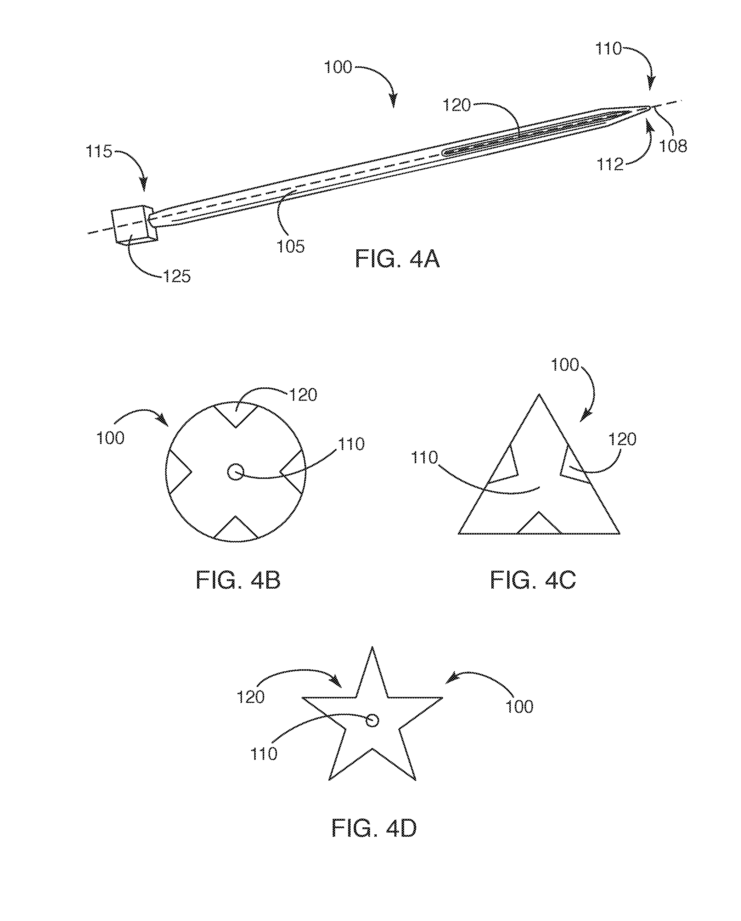
[0040] FIG. 4A illustrates a perspective view of a grooved needle in accordance with a representative embodiment;
[0041] FIGS. 4B-4D respectively illustrate cross-sectional views of some embodiments of the grooved needle;
[0042] FIG. 5 illustrates a perspective view showing grooved knitting needles in use in accordance with a representative embodiment;
[0043] FIG. 6 shows a perspective view of the grooved knitting needle in accordance with some representative embodiments;
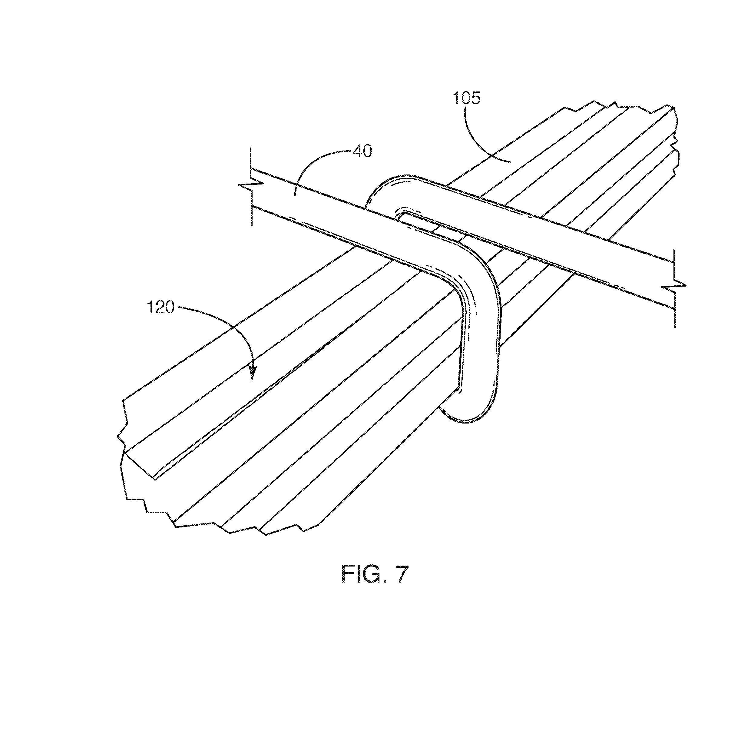
[0044] FIG. 7 shows a portion of the grooved knitting needle having a piece of yarn (or other material) wrapped around the needle in accordance with a representative embodiment;
[0045] FIG. 8 illustrates a distal portion of the grooved knitting needle in accordance with a representative embodiment;
[0046] FIG. 9 illustrates a proximal end of the grooved knitting needle in accordance with a representative embodiment;
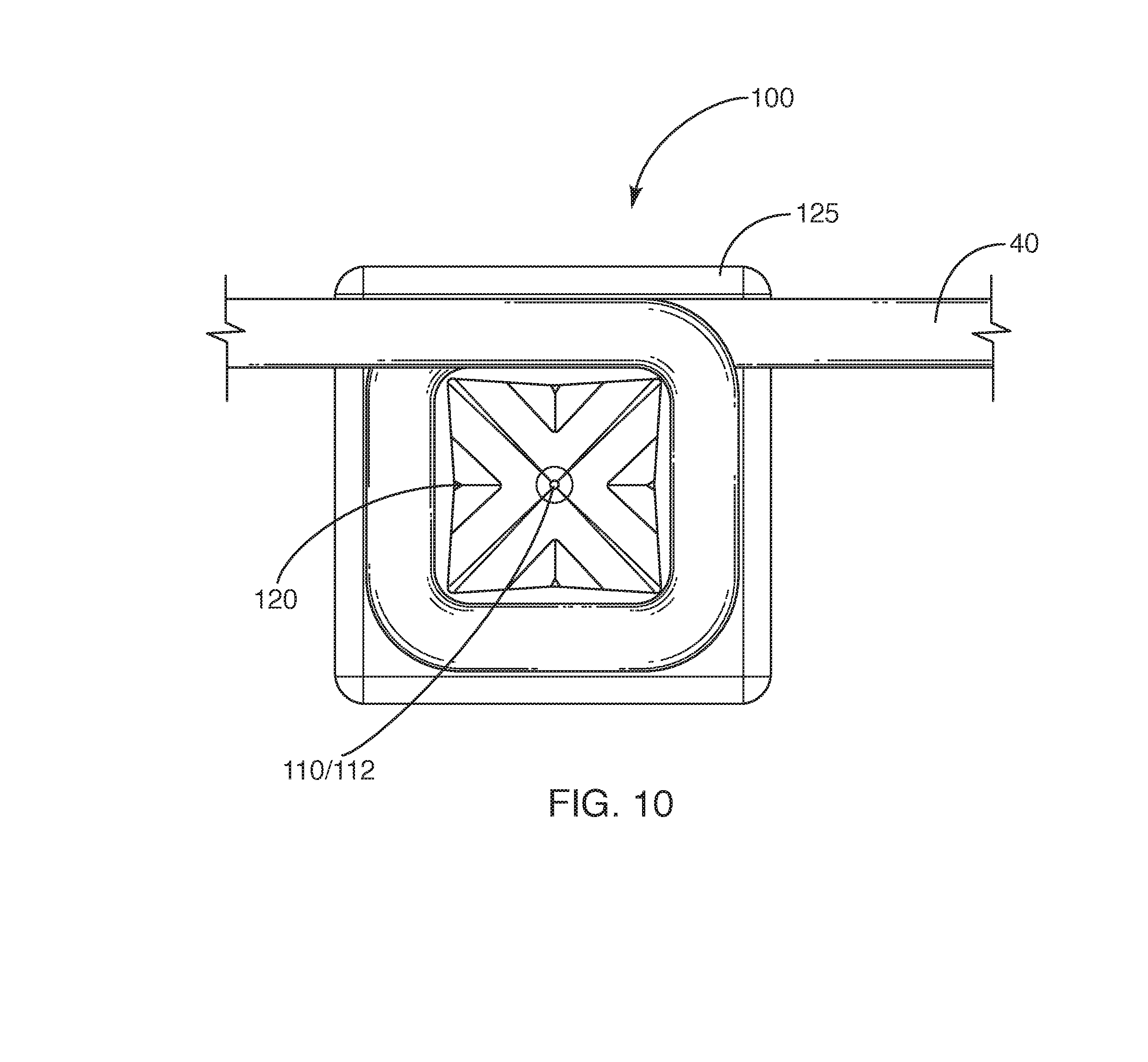
[0047] FIG. 10 illustrates a distal elevation view of the grooved knitting needle with a piece of yarn wrapped around the needle in accordance with a representative embodiment;
[0048] FIG. 11 illustrates a perspective view of a representative embodiment of the grooved knitting needle;
[0049] FIG. 12A illustrates a side view of the grooved knitting needle in accordance with a representative embodiment;
[0050] FIG. 12B illustrates a distal elevation view of a representative embodiment of the grooved needle;
[0051] FIG. 12C illustrates a proximal elevation view of a representative embodiment of the grooved needle;
[0052] FIG. 13A illustrates a side view of a representative embodiment of the grooved knitting needle;
[0053] FIG. 13B illustrates an enlarged view of a distal portion of the needle of FIG. 13A;
[0054] FIG. 13C illustrates a cross-sectional view of the needle of FIG. 13B taken along line N-N;
[0055] FIG. 13D illustrates a cross-sectional view of the needle of FIG. 1313 taken along line O-O;
[0056] FIG. 14A illustrates a side view of a representative embodiment of the grooved needle;
[0057] FIG. 14B illustrates an enlarged view of a distal tip of the needle from FIG. 14A;
[0058] FIG. 14C illustrates a distal elevation view of the needle from FIG. 14A;
[0059] FIG. 15A illustrates a side view of a representative embodiment of the grooved needle, the needle being of any suitable length;
[0060] FIG. 15B illustrates a distal view of the portion of the needle from FIG. 15A, with such portion taken between lines P-P and Q-Q;
[0061] FIG. 16 illustrates a side view of a proximal end of a representative embodiment of the grooved needle;
[0062] FIG. 17 illustrates a perspective view of two grooved needles that are coupled together with a coupling mechanism;
[0063] FIG. 18 illustrates a side view of a representative embodiment of the grooved needle having a tapered proximal end;
[0064] FIG. 19 illustrates a perspective view of a distal portion of the needle from FIG, 18;
[0065] FIG. 20 illustrates a perspective view of a proximal end of the grooved needle, the proximal end of the needle defining a recess in accordance with some embodiments;
[0066] FIG. 21 illustrates a representative embodiment of a coupler for coupling two grooved needles together;
[0067] FIG. 22 illustrates a plan view of a knitted material prepared with two grooved needles that are coupled together;
[0068] FIG. 23A illustrates a perspective view of the grooved needle comprising a portion of a coupler in accordance with a representative embodiment;
[0069] FIGS. 23B and 23D each illustrate a side view of the grooved needle in accordance with representative embodiments;
[0070] FIG. 23C illustrates a distal elevation view of the needle from FIG. 23A;
[0071] FIG. 23E illustrates a proximal elevation view of the needle from FIG. 23A;
[0072] FIG. 24A illustrates a side, cross-sectional view of a representative embodiment of the grooved needle;
[0073] FIG. 24B illustrates a side, cross-sectional view of a representative embodiment of the grooved needle;
[0074] FIG. 24C illustrates a distal elevation view of the needle from FIG. 24A; and
[0075] FIG. 24D illustrates a distal elevation view of the needle from FIG. 24B.
DETAILED DESCRIPTION OF THE INVENTION
[0076] Some implementations of the described invention relate to a knitting needle. While this knitting needle can have any suitable characteristic or component, in some cases, it defines a groove that extends longitudinally along a length of an outer surface of the knitting needle. In some cases, the groove opens near a pointed end (or a distal end) of the grooved knitting needle. Thus, in some cases, a tip of a second knitting needle can run longitudinally through the groove, such that the tip of the second needle is able to readily pass under a portion of yarn (or other material) that is on the described grooved knitting needle. In some cases, a proximal end of the described knitting needle comprises an object that is wider than a width of a shaft of the needle so as to prevent yarn loops from falling off of the proximal end of the needle. In some cases, the described knitting needle is coupled with another needle. While such coupling can be achieved in any suitable manner, in some cases, the two needles are coupled together with a non-resilient coupler. Additionally, in some instances in which the grooved knitting needle is used with a second needle (whether or not the two needles are coupled together), at least one of the needles comprises a distinguishing feature that allows the two needles to be readily distinguished. For instance, the two knitting needles can be different colors.
[0077] While the described knitting needle can comprise any suitable component or characteristic, FIGS. 4A-16 show that, in some embodiments, the knitting needle 100 comprises an elongated shaft 105 having a distal end 110 and a proximal end 115, where one or more grooves 120 are defined in the shaft. Additionally, some embodiments of the needle comprise an enlarged portion (or enlargement 125) at the needle's proximal end 115. Additionally, while some embodiments of the described needles are used independently or without being coupled together (where such needles may be referred to herein as straight needles), in some other embodiments, two or more needles are connected together with a coupling mechanism 130 (with such needles sometimes being referred herein to as circular needles, circular needle systems, and as variations thereof, see FIGS. 17 and 17-24D).
[0078] In accordance with some embodiments, the described grooved needle 100 (or straight needle, where the needle is not coupled to another needle) comprises a needle of any suitable cross-sectional shape, including, without limitation, a square shape, a triangular shape, a pentagonal shape, a cat-eye or cat-iris shape, a polygonal shape, a four-pointed star shape, a three-pointed star shape, a five-pointed star shape, a multi-pointed star shape, a multi-cornered shape, a multi-process shape, an irregular shape, a regular shape, an asymmetrical shape, a symmetrical shape, and/or any other shape that allows the described needle to function as set forth herein. Alternatively, sonic embodiments include the use of a round (e.g., as shown in FIG. 4B), cylindrical, elliptical, and/or otherwise rounded knitting needle 100 with a groove 120 or grooves along its shaft 150; a triangular knitting needle with a groove or grooves on one or more of its sides (e.g., as shown in FIG. 4C), a star-shaped knitting needle (as shown in FIG. 4D), and/or any knitting needle with a groove or grooves extending longitudinally on one or more of the needle's sides or external surfaces. In some embodiments, however, the described grooved needle (e.g., straight needle) comprises a square knitting needle (e.g., as shown in FIG. 4A) that is configured to be used when knitting yarn 40 (or any other material) into flat panels of fabric and/or for any other suitable purpose.
[0079] While the drawings included herein (e.g., FIG. 4A) show embodiments in which the shaft 105 of the grooved needle 100 is substantially straight, in some other embodiments, the needle is curved, bent, angled, and/or otherwise varies from being straight throughout all or a portion of its longitudinal length (or the length of the needle from its distal 110 to proximal 115 ends).
[0080] In accordance with some embodiments (and as mentioned), the described knitting needle has a recessed portion, gully, gutter, channel, depression, space between raised ridges or rails, channel, and/or other groove 120 in one or more of its faces or external surface. Indeed, in some embodiments, as shown in FIGS. 6, 7, 8 10, 11, 12A, 1213, 13A-13C, 14A-15B 17-20, and 23A-24D, a square grooved needle 100 defines a groove 120 on each of its four sides (or any other number of sides). That said, alternative methods include cutting, milling, molding, and/or otherwise forming a groove into the face of one side, two sides, three sides, or any other suitable combination of the sides of the square knitting needle or a knitting needle of a different shape.
[0081] The grooved needle 100 can be any suitable length. Indeed, in some embodiments, the length of the described needle (e.g., a straight needle) is between about 1 inch (25.4 mm) and about 18 inches (457.2 mm), or that is within any subrange thereof. Indeed, in some embodiments, the described straight needle is between about 3 inches (76.2 mm) and about 11 inches (279.4 mm) long (e.g., about 9 inches (228.60 mm).+-.1 inch or 25.4 mm). Alternative embodiments allow for other lengths of the straight, grooved knitting needles may depend upon the strength of the material used.
[0082] The described grooved knitting needle 100 (e.g., straight, grooved needle) can be manufactured to be virtually any suitable size that allows it to function as described herein. In some embodiments, however, the needle is manufactured in one or more sizes equivalent to conventional round needles (e.g., from U.S. size 3 through U.S. size 11, from European size 0 through European size 11, and/or any other possible size). Alternative U.S. and European sizes may also be considered and chosen.
[0083] In some embodiments, the described knitting needles 100 are manufactured from one or more woods, bamboos, metals, nylons, plastics, carbon fibers, ceramics, acrylics, natural materials, types of glass, synthetic materials, and/or any suitable material or materials.
[0084] The described straight knitting needles 100 can also be manufactured in any suitable manner, including, without limitation, via cutting, milling, molding, injecting, spraying, 3D printing, additive manufacturing, extruding, stamping, pressing, shaving, sanding, grinding, etching, deposition, and/or any other suitable method that is applicable to the chosen material.
[0085] In some embodiments, the distal tip 112 of the described knitting needle 100 (see e.g., FIG. 4A) transitions or tapers to a pointed tip beginning any suitable distance from the distal end 110 of the needle. Indeed, in some embodiments, the straight knitting needle transitions or tapers to a point beginning at between about 5 mm and about 80 mm or any subrange thereof (e.g., about 25.4 mm.+-.5 mm) proximally from the distal end of said needle and narrowing distally into the distal tip, creating a point (or tip) having any suitable diameter (or other shape). In some embodiments, the distal tip has a diameter (or width) that is between about 0.1 mm and about 1 cm, or any subrange thereof (e.g., about 5 mm.+-.2 mm in diameter) Alternative ds allow, however, for a shorter or longer taper and a larger or smaller tip or point dimension. In any case, some embodiments of the distal tip are sized and shaped to fit within, and slide through, the described groove 120.
[0086] In some embodiments, the distal tip 112 or point of the knitting needle 100 (e.g., a straight needle) is radius-ed to any suitable size. Indeed, in some embodiments, the distal tip is radius-ed to between about 0.01 mm and about 1 cm, or any subrange thereof (e.g., about 0.25 mm.+-.0.1 mm). Alternative methods allow for a smaller or larger radius of the distal tip or point of the described needle.
[0087] In some embodiments, the groove 120 on the described grooved knitting needles 100 (e.g., straight grooved needles) begins at any suitable distance from the needle's distal tip 112. Indeed, in some embodiments, the groove begins at, and runs proximally from, a distance between about 0.001 mm and about 50 mm, or any subrange thereof (e.g., about 11.37 mm mm), from the distal tip of the needle. In some non-limiting embodiments, the placement of the groove on all other larger or smaller sized grooved knitting needles is proportionate to the distal tip of the described square, grooved needles. Alternative methods include beginning the groove closer to the distal tip or farther from the tip of the square knitting needle and/or a knitting needle of any other suitable shape. Indeed, in some non-limiting embodiments, the groove begins about 11.37 mm.+-.5 mm from the distal tip of the needle and continues in a line substantially parallel to a longitudinal axis 108 of the shaft 105 of the needle any suitable distance, including, without limitation, between about another 10 mm and about 20 cm, or any subrange thereof (e.g., between about 50 mm and 100 mm in length or even about another 75.95 mm.+-.10 mm) toward the proximal end 115 of the needle.
[0088] The groove 120 can extend any suitable depth into the described knitting needle 100 that allows the needle function as set forth herein. In some embodiments, the groove extends into the needle between about 1/100 and 9/10 (or any subrange thereof) of the total depth of the shaft 105 of the needle. In accordance with some embodiments, however, the depth of the groove formed into one or more faces of the knitting needle is between about 1/5 and about 1/3 (e.g. about 1/4) of the total depth of the knitting needle.
[0089] The grooves 120 in the described needle 100 can be any suitable shape, including, without limitation, being angled, rounded, curved, squared, rectangular, polygonal, oval, V-shaped, U-shaped, dove-tailed, and/or any other suitable shape. In some embodiments in which the groove or grooves formed in the needle are angled (e.g., so as to have a V-shape), the grooves can be formed in the needle so as to have any suitable angle between intersecting walls of the groove. Indeed, in some embodiments, the inner walls of the groove are disposed with respect to each other at an angle a between about 5 degrees and about 160 degrees (or any subrange thereof). In some embodiments, for instance, the groove is approximately a 90 degree right angle that is cut, milled, molded, and/or otherwise formed directly into the middle of the face on each of the sides of the knitting needle 100 (see e.g., FIG. 15B), Alternative methods are to cut, mill, mold, and/or otherwise form the 90.degree. right angle (and/or a groove of any other suitable angle and/or shape) nearer to either edge on the face of one of more sides of the knitting needle (e.g., in four sides of a square needle) or farther from either edge on the face of each of one or more sides of the knitting needle or (as mentioned above) to create a groove that is more than 90.degree. or less than 90.degree..
[0090] The groove 120 can run in any suitable direction that runs longitudinally down a length of the needle 100 (e.g., by running parallel with a length or longitudinal axis of the needle, by being angled on the needle, by twisting around a portion of the needle, by following a curved path, by having a zig-zag path, and/or by otherwise extending down a length of the needle). By way of non-limiting illustration, FIG. 4A shows an embodiment in which the groove 120 runs substantially parallel to a longitudinal axis 108 of the needle 100. Alternative methods, however, include placing the groove at any angle other than parallel to the shaft on one, two, three and/or any other combination of sides of the knitting needle, Additionally, in some embodiments, there are more than one groove on one, any, and/or all sides of the knitting needle. That said, in some embodiments, one groove runs in a line that is substantially parallel to the shaft of the needle, in the middle of the face on each of the four sides of a square, straight, grooved, knitting needle (see e.g., FIGS. 14A-14B).
[0091] In accordance with some embodiments, the described knitting needles 100 optionally incorporate one or more shallow concavities 128 on one or more faces of the various sides of the knitting needle, together with a groove 120 that is cut, milled, molded, and/or otherwise formed into the concavity on the face of each of the sides of the knitting needle (see e.g., FIGS. 14C and 15B). In this regard, the concavities can extend any suitable amount into the needles, including, without limitation, between about 1/10 0 and about 9/10 (or any subrange thereof) of the total thickness of the needle's shaft. Indeed, in some embodiments, the concavity is between about 1/20 and about 1/4 of the total thickness of the needle.
[0092] In some embodiments, the concavity 128 spans a distance from one edge (or corner) of the knitting needle 100 to an opposite edge (or corner) of the knitting needle on the face of one or more sides of the knitting needle. Alternative embodiments, however, include a concavity which does not span the distance from one edge of the knitting needle to the opposite edge of the knitting needle on the face of each of the sides (e.g., on four sides) of the knitting needle. In some additional alternative embodiments, the needle includes a concavity which appears on the face of one, two, three, or more sides, and/or any combination of sides of the knitting needle with one or more accompanying grooves 120 disposed in one, two, or more of the concavities (see e.g., FIG. 14C). In still other embodiments, the needle defines one or more concavities which do not include a groove in all (or in some to embodiments, any) face of the sides of the knitting needle. In still other embodiments, the needle includes a groove on only one, two, three faces, and/or any combination of faces, on the sides of the knitting needle. In some embodiments, however, the described knitting needle comprises a shallow concavity on the face of each of the four sides (or any other suitable number of sides) of the knitting needle, together with a groove that is c milled, molded, and/or otherwise formed into the concavity on the face of each of the four (or any other suitable number of) sides of the knitting needle. In some embodiments, the depth of the concavity on the face of each of the sides of the described knitting needle, whether presented with the described groove or not, is between about 0.001 mm and about 8 mm, or any subrange there of (e.g., about 0.04 mm.+-.0.02 mm). That said, alternative depths of the concavity on the face of each of the sides of the straight knitting needle are contemplated herein. In this regard, the concavity can perform any suitable purpose, including, without limitation, causing corners of the knitting needle to be somewhat more pointed to help increase friction between the needle and yarn wrapped around it.
[0093] In some embodiments, the described knitting needle 100 (e.g., straight, grooved needle) optionally has a square cube, a rectangular prism-shaped object, a ball, a figurine, a decorative object, a prism-shaped object, a cross member, and/or any suitably shaped object or enlargement disposed at the proximal end 115 of the needle. By way of non-limiting illustration, FIG. 11 shows an embodiment in which the proximal end 115 of the needle 100 comprises a cube-shaped enlargement 125. In any case, the object at the proximal end of the needle can be any suitable size that allows the object to prevent yarn (or any other suitable material) from falling off of the proximal end of the needle during the knitting process. Indeed, in some embodiments, the object disposed at the proximal end of the needle is between about 1.1 and about 10 times, or any subrange thereof, of the thickness of the needle itself. In some embodiments, the object at the distal end of the needle is between about 1.5 times and about 3 times as thick as the width or diameter of the needle.
[0094] Where the described needle 100 comprises an enlargement at the proximal end 115 of the needle, such object can be coupled to the needle in any suitable manner, including, without limitation, by being: integrally formed with, glued to, nailed to, fastened to, friction fit with, threaded with, threaded to, printed with, clipped to, mechanically engaged with, and/or otherwise formed with and/or coupled to the needle. In any case, such enlargement can comprise any suitable material, including, without limitation, wood, plastic, acrylic, nylon, carbon fiber, metal, hardened rubber, natural materials, synthetic materials, and/or any other suitable material. Alternative embodiments to those described above also use other shapes, manufactured from other materials, and/or in other sizes which also function as an enlargement or stop to keep yarn from falling off the proximal end. Alternatively, some embodiments of the needle include no stop or enlargement at all.
[0095] According to some embodiments, the described knitting needles 100 are relatively short, square (and/or any other suitable shape) knitting needles. While such needles can be used for any suitable purpose, in some cases, they are used when knitting projects that begin or end in a very tight circumference, such as gloves, socks, small hats, small sleeves, etc. In some cases, they are used for knitting "in the round" or they may be used to knit flat panels. In some embodiments, these relatively short, square (or otherwise shaped) needles have a groove 120 on the face of one or more sides of the needles and are connected together at the proximal ends of the knitting needles by a coupling mechanism or coupler (e.g., a cord, a string; a woven, flexible, nylon cord, a flexible rope, a ribbon, a piece of flexible fabric, a piece of cloth, a strap, a cable, and/or any other suitable material). In some embodiments, the coupler extending between two knitting needles (e.g., circular needles) is mostly, if not completely, unbiased, having no memory. Indeed, in some embodiments, the coupler is non-resilient. By way of non-limiting illustration, FIG. 17 shows an embodiment in which a coupler 130 (e.g., a braided nylon cord) joins two needles 100 together.
[0096] Although the drawings included herein show knitting needles 100 in circular systems as being square, alternative embodiments include the use of relatively short, round, knitting needles with a groove or grooves along the shaft, triangular needles with a groove or grooves on one or more of its sides, and/or any polygonal or suitable shaped knitting needle (e.g., as discussed. above or otherwise) with a groove or grooves on one or more of its sides or external surfaces.
[0097] In some embodiments, the length of each knitting needle 100 in the circular needle system is between about 1 inch (25.4 mm) and about 12 inches (304.8 mm), or any subrange thereof (e.g., about 4 inches (or about 114.31 mm).+-.1.5 inches or 38.1 mm). Alternative embodiments allow for other lengths of the knitting needles in circular systems, but such lengths may depend upon the strength of the material used.
[0098] The described needles 100 used in circular systems can be any suitable size that allows them to function as described herein. In some embodiments, the each of the knitting needles 100 in the described circular knitting needle system is manufactured in one or more sizes equivalent to conventional round needles--from U.S. size 3 through U.S. size 11, from Europe size 0 through European size 11, etc. Alternative U.S., European, and other sizes may also be considered and chosen.
[0099] The described knitting needles 100 in the described circular systems can comprise any suitable material. In some embodiments, however, the knitting needle of the circular knitting systems (like the other needles described herein) can comprises one or more pieces of wood, bamboo, metal, nylon, plastics, polymers, rubbers, carbon fibers, natural materials, synthetic materials, and/or any other suitable materials that allow the needle to function as intended.
[0100] Additionally, the circular knitting needle system can be manufactured in any suitable manner, including, without limitation, via cutting, milling, molding, injecting, spraying, extruding, sanding, etching, polishing, 3D printing, and/or any other method that is applicable to the chosen material.
[0101] In some embodiments, the distal tip of one or more of the knitting needles 100 in the described circular knitting systems transitions or tapers to a pointed tip (e.g., the distal tip 112) beginning at a distance between about 5 mm and about 60 mm, or any subrange thereof (e.g., about 25.4 mm.+-.5 mm) proximal to the distal end 110 of said needle toward the distal tip 112 of the needle, creating a pointed tip having any suitable diameter (or other suitable shape or size). Indeed, in some embodiments, the distal tip of needles in the described circular knitting system (e.g., shown in FIG. 17) has a diameter (or width) that is between about 0.1 mm and about 1 cm, or any subrange thereof (e.g., about 5 mm.+-.2 mm in diameter. Alternative embodiments allow for a shorter or longer taper and/or a larger or smaller tip or point dimension.
[0102] In some embodiments, the distal tip 112 or point of one or more of the knitting needles in the described circular knitting systems is radius-ed (or otherwise shaped) to any suitable size. Indeed, in some embodiments, the distal tip is radius-ed to between about 0.01 mm and about 1 cm, or any subrange thereof (e.g., about 0.25 mm.+-.0.1 mm). Alternative embodiments comprise a smaller or larger radius of the distal tip and/or point of the described needle.
[0103] In some embodiments, the groove 120 on the face of each of the sides of the knitting needles 100 in the described circular systems are cut, milled, molded, and/or otherwise formed into the face of one or more of the sides (or surfaces) of the knitting needle. Indeed, in some embodiments, a groove is cut, milled, molded, and/or otherwise formed into the face of one side, two sides, three sides, four sides, or any suitable combination of sides of the knitting needle.
[0104] In some embodiments, the length of the groove 120 on the described knitting needles 100 in the circular systems begins at any suitable distance proximal to the needle's distal tip, including, without limitation, between about 0.001 mm and about 50 mm, or any subrange thereof (e.g., about 11.37 mm.+-.2 mm) from the distal tip of the needle, and continues toward the proximal end of the needle in a line substantially parallel to a longitudinal axis of the shaft 105 (or along any other path, as discussed above) of the needle any suitable distance, including, without limitation, between about another 5 mm and about another 500 mm (e.g., about 19.82 mm.+-.5 mm). In some embodiments, the placement of the grooves on other larger or smaller sized knitting needles is proportionate to the distal tip of the knitting needles. Alternative embodiments include beginning the grooves closer the distal tip or farther from the tip of the knitting needles.
[0105] The length of the groove on the knitting needles 100 in the described circular knitting needle systems can (as discussed above) be any suitable length, including, without limitation, between about 5 mm and about 150 mm in length, or any subrange thereof (e.g., about 31.57 mm long.+-.5 mm). In some embodiments, different sizes of the described needles (e.g., circular needles) optionally have similar groove lengths. That said, in some alternative embodiments, the length of the groove varies to be any suitable length along the shaft 105 of the knitting needle in the described circular systems.
[0106] As discussed above, the groove 120 can extend any suitable depth into the described knitting needle 100 used in circular systems that allows the needles to function as set forth herein. In some embodiments, the groove extends into one or more of the needles between about 1/100 and 9/10 (or any subrange thereof) of the total depth or thickness of the shaft of the needle. In accordance with some embodiments, however, the depth of the groove that is formed into one or more faces of the knitting needles in circular systems is about 1/4 of the total depth of the corresponding knitting needle. Alternative depths, however, are contemplated herein.
[0107] The grooves 120 in the needles 100 of the described circular knitting systems (as in the other grooved needles discussed herein) can be any suitable shape, including, without limitation, being angled, being rounded, curved, squared, rectangular, polygonal, oval, V-shaped, U-shaped, and/or any other suitable shape. In some embodiments in which the groove or grooves formed in the needle are angled (e.g., are V-shaped), the grooves can be formed in the needle so as to have any suitable angle between intersecting walls of the groove. Indeed, in some embodiments, the inner walls of the groove are disposed with respect to each other at an angle .alpha. between about 10.degree. and about 160.degree. (or any subrange thereof; see e.g., FIG. 15B). In some embodiments, for instance, the groove is a 90.degree. right angle, cut, milled, molded, and/or otherwise formed directly into the middle of the face of one or more of the sides of the needles in the described circular knitting needle system. In accordance with some alternative embodiments, grooves are cut, milled, molded, and/or otherwise formed in one or more of the needles as a 90.degree. right angle placed nearer to either edge on the face of each of the sides of the needle or farther from either edge on the face of one or more of the sides of the needle, or a groove that is less than 90.degree. or more than 90.degree. is formed in the needle. The groove may be cut, milled, molded, or otherwise formed into other shapes or configurations (e.g., a rectangular groove, a circular groove, an ovular groove, and/or any other suitable shape).
[0108] While the groove 120 may follow any suitable path in the needle 100 of the described circular knitting systems (e.g., a curved path, a zig-zag path, a twisting path, and/or any other suitable path along the needle), in some embodiments, the groove travels in a parallel line longitudinally along the shaft 105 of one or more of the knitting needles in the circular system. Alternative methods include placing the groove at any angle other than parallel to the shaft on one, any or all sides of the needle. Additionally, in some embodiments, there is more than one groove on one, two, three, four, and/or any other suitable number of the sides of the knitting needle.
[0109] In some embodiments, the knitting needles 100 in the described circular systems incorporate a shallow concavity 128 on the face of one or more sides of the knitting needles, together with a groove that is cut, milled, molded, and/or otherwise formed into the concavity on the face of one or more sides of the knitting needle. In this regard, the concavities can extend any suitable amount into the needles, including, without limitation, between about 1/100 and about 9/10 (or any subrange thereof) of the total thickness of the needle. Indeed, in some embodiments, the concavity is between about 1/20 and about 1/4 of the total thickness of the needle,
[0110] In some embodiments, the concavity 128 in needles 100 in a circular system spans the distance from one edge of the knitting needle to the opposite edge of the knitting needle on the face of one or more sides of the knitting needle. Some alternative embodiments, however, include a concavity which does not span the distance from one edge of the straight, square (or other shaped) knitting needle to the opposite edge of the knitting needle on the face of one or more sides (e.g., on four sides) of the knitting needle in the circular system. In some additional alternative embodiments, the needle includes a concavity which appears on the face of one, two, three, or more sides, and/or any combination of sides of the knitting needle with one or more accompanying grooves 120 disposed in one, two, or more of the concavities (see e.g., FIG. 14C). In still other embodiments, the needle defines one or more concavities which do not include a groove in all (or in some embodiments, any) face of the sides of the knitting needle. In still other embodiments, the needle includes a groove on only one, two, three, four faces, and/or any other combination of faces, on the sides of the knitting needle. In some embodiments, however, the knitting needles used in the described circular systems comprise a shallow concavity on the face of each of the four sides (or any other suitable number of sides) of one or more of the knitting needles, together with a groove that is cut, milled, molded, and/or otherwise formed into the concavity on the face of each of the four (or any other suitable number of) sides of the knitting needle.
[0111] In some embodiments, the depth of the concavity 128 on the face of one or more sides of the knitting needles 100 in the described circular knitting needle system, whether presented with the described groove 120 or not (as in some of the other needles described herein), is between about 0.001 mm and about 8 mm, or any subrange thereof (e.g., about 0.04 mm.+-.0.02 mm). That said, alternative depths of the concavity on the face of each of the sides of the circular knitting needles are contemplated herein.
[0112] In some embodiments, the two knitting needles 100 in the described circular system are joined together at their proximal ends 115 via one or more cords, ropes, ribbons, strings, straps, and/or other suitable connecting mechanisms or couplers. Indeed, as discussed above, in some embodiments, a smoothly woven, flexible nylon cord is used to connect two knitting needles at the proximal ends of the needles. In some such embodiments, the cord has no memory or spherical bias. Indeed, in some embodiments, the cord (or other coupler) is non-resilient (or does not bias the two coupled needles to be moved closer together or further apart from each other).
[0113] Although the various needles 100 can be coupled to the connecting mechanism or coupler 130 in any suitable manner (e.g., via glue; a knot; having the connection mechanism be looped around a portion of the needles; injection molding; one or more threaded engagements, clips, mechanical engagements, frictional engagements, barbs, or other connectors; and/or in any other suitable manner), in some embodiments, the connection of the smoothly woven, flexible nylon cord (or other suitable coupler) to the proximal ends of two grooved knitting needles comprising wood and/or any other suitable material is accomplished by gluing the coupler into a spherical, cylindrical, and/or other suitable shaped) void 135 (see e.g., FIGS. 20 and 24A-24B) at the proximal ends 115 of two of the needles 100. In some alternative embodiments, however, the smoothly woven, flexible nylon cord is connected into the proximal ends of two wooden needles by methods other than gluing. Indeed, FIG. 24B shows an embodiment in which the coupler 130 is frictionally and/or mechanically connected to the needle 100 via a clip 137.
[0114] In some embodiments, the connection of the smoothly woven, flexible nylon cord (and/or any other suitable coupler) to be proximal ends 115 of two knitting needles 100 (e.g., needles in a circular knitting system) wising carbon fiber and/or any other suitable material is accomplished by attaching the cord (or coupler) into a spherical or cylindrical void 135 at the proximal ends of two of the needles prepared for the cord in any acceptable manner for attaching objects to one another. In some alternative embodiments, the smoothly woven, flexible nylon cord (and/or any other suitable connection mechanism) is connected to the proximal ends of two carbon fiber needles by other methods (e.g., one or more frictional engagements, clamps, welds, etc.). In some embodiments, the connection of the smoothly woven, flexible nylon cord (or any other suitable coupler) to the proximal ends of two grooved knitting needles (e.g., a circular knitting system) comprising plastic, acrylic, nylon, and/or any other suitable material is accomplished by over molding the cord into the body of the needles during the injection molding process. In some embodiments, an alternative glue-in method for connecting the smoothly woven, flexible nylon cord (and/or other suitable coupler) into one or more voids and/or any other suitable receptacle/connection point that is prepared at the proximal ends of two plastic, acrylic, nylon, and/or other suitable knitting needles of a circular knitting system may be utilized.
[0115] In some embodiments, the smoothly woven, flexible nylon cord (and/or any other suitable coupler 130) is connected to the proximal ends 115 of two circular knitting needles (namely one or more of the described grooved needles 100) that comprises aluminum, stainless steel, nickel plated brass, platinum, and/or any other suitable material by means of a multiple (e.g., two, three, four, etc.) pronged clip 137 (see e.g., FIG., 24B), over molded onto each end of the cord which is inserted into a void 135 in the proximal ends 115 of each of the needles 100 which is prepared for the clip. In this regard, the clip may or may not be manufactured to swivel.
[0116] In some embodiments, the smoothly woven, flexible nylon cord (and/or other suitable coupler 130) is flexible and has no memory or spherical bias. In some such embodiments, the connection mechanism comprises nylon, another material having one or more attributes similar to nylon, and/or any other suitable material. In one example, the coupler comprises any suitable material that allows the cord to be able to bend onto itself without causing noticeable damage to the cord. Some alternative embodiments utilize other materials which have no memory or spherical bias and are able to bend onto themselves without causing noticeable damage to the connection mechanism or joint. In other words, while some knitting systems comprise a resilient or semi-resilient connector that tends to bias connected needles in on or more positions, some embodiments of the coupler 130 are not resilient (e.g., comprise flexible cord, cloth, twine, and/or any other suitable material).
[0117] In some cases, the diameter of the smoothly woven, flexible nylon cord (and/or any other suitable coupler 130) that is prepared for different sizes of grooved knitting needles (e.g., grooved needles in a circular system) is relative to the void 135 in the proximal ends 115 on each of the two knitting needles. Alternative diameters may be chosen which fit into a void (and/or other coupler or receptacle) prepared to accept the cord (and/or other coupling mechanism) on the proximal end of the needles.
[0118] In some embodiments, the smoothly, woven, flexible nylon cord (and/or other coupler 130) of the grooved knitting needles in a circular system may be manufactured in various lengths, including, but not limited to: being between about 2 inches (50.8 mm) and about 60 inches (1.524 m), or any subrange thereof (e.g., about 16 inches or 406.4 mm, about 24 inches or 609.6 mm, about 30 inches or 762 mm, etc.). Alternative sizes may be considered and chosen. In some embodiments, the smoothly woven, flexible nylon cord (or other coupler) may be interchangeable when used with the clip 137 (and/or other suitable mechanism)
[0119] In accordance with some embodiments, the described grooved knitting needle 100 (e.g., straight needles or needles that are not coupled together at their proximal ends 115) is able to: enable a knitter when working flat to control and improve tension; easily knit with consistent, even tension, thus creating a beautiful fabric; reduce human errors by providing a groove 120 on the face of one or more of the sides of the needle, giving the working needle increased ability to slide under the right (or other suitable) leg of a stitch and through the center of the loop without splitting the stitch; enable the knitter to decrease the stitches (k2tog, k3tog, etc.) more easily; and/or enable a knitter to "see" or be aware of one of the little known causes of uneven tension: "needle roll," which gives the knitter power to control this roll to their benefit.
[0120] In accordance with some non-limiting embodiments, the described grooved knitting needles 100 (e.g., when used in circular knitting system) are configured to: enable the knitter when working "In the Round" or knitting small circular items, such as gloves, socks, small hats, small sleeves, etc., to control and improve tension; to easily knit with consistent, even tension, thus creating a beautiful fabric; reduce human errors by providing a groove 120 on the face of each of the sides of the needle, giving the working needle increased ability to slide under the right (or other suitable) leg of the stitch and through the center of the loop without splitting stitches; enable the knitter to decrease the stitches (k2tog, k3tog, etc.) more easily; allow the knitter to close the small hole at the beginning or ending of a very small circular project without having to switch to the clumsy DPN method; avoid the numerous problems and weaknesses caused by using a flexible connecting cord which has a memory or spherical bias; and/or enable the knitter to "see" or be aware of one of the little known causes of uneven tension: "needle roll," which gives the knitter power to control this roll to their benefit.
[0121] In addition to the foregoing, the described grooved needles 100 can be modified in any suitable manner. Indeed, although some embodiments of the needles are relatively straight (as illustrated in the drawings), in some other embodiments, the needles are curved, comprise a curved section, and/or are otherwise varied from conventional needles (e.g., as mentioned above), while still comprising at least one groove and/or concavity (as described herein). In another example, some embodiments of the described circular knitting system comprises one needle with grooves 120, while the other needle is free from grooves.
[0122] In still another example, in some embodiments in which two grooved needles 100 are used together (including, without limitation, for straight needles or circular needles), at least one of the two needles comprises a distinguishing feature that allows the two needles to be readily distinguished. In this regard, some examples of such distinguishing features include, but are not limited to, one of the needles comprising a different color, shape, marking, identifier, and/or other characteristic than the other needle. Indeed, in some implementations, the two needles each comprise a different dominant color. By way of non-limiting example, while one needle is red, the other needle can be grey. In any case, where the two needles are readily distinguishable, such a feature can serve any suitable purpose. For instance, by having readily distinguishable needles, a knitter can easily remember which needle is the working needle.
[0123] In this regard, it is a common occurrence when knitting a stockinette pattern (one row of garter stitches followed by one row of purl stitches, repeated) on a pair of conventional knitting needles to forget which of the two basic stitches (garter or purl) a knitter has just employed. This forgetting may happen at any time, including after the knitter has completed a whole row and is about to begin a new row or when the knitter sets the work down for a period of time and then comes back to the work to continue knitting. When the knitter forgets, he or she will need to examine the knitted work to discover which stitch has just been employed. For a beginning knitter, however, it is often confusing to "read" the knitted stitches. Thus, one solution to such a problem is having the two needles be readily distinguishable.
[0124] By way of example, where two knitting needles (e.g., grooved needles 100 and/or other needles) are readily distinguishable (e.g., by having one needle have a first dominant color (or other distinguishing feature), and the other needle have a second dominant color (or other identifiable feature or lack thereof)), the process of identifying the working and resting needles (and the type of stitches that have already done) can be relatively easy. In this example, if the knitter begins by knitting garter stitches using a red needle, for instance, in the working position (where the term working needle, working position, and variations thereof may refer to a needle that is relatively free of loops and ready to begin knitting new loops and is often, but not necessarily, held in the dominant hand) and where the knitter is using a grey needle, for instance, in the resting position, with the grey resting needle having multiple loops waiting to be taken off (the resting needle often being held in the non-dominant hand), and the knitter continues knitting to the end of a row, the knitter will then have all of the loops on the red needle which now becomes the resting needle. In this example, the grey needle, which is now free of its loops, becomes the working needle, and the knitter will then knit a row of purl stitches. In this way, the knitter may see at a glance which stitch to employ next. Indeed, in this example, when the red needle is in the working position, the knitter will know to knit garter stitches. In contrast, when the grey needle is in the working position the knitter will know to knit purl stitches.
[0125] Continuing with this non-limiting example, if the knitter sets the work aside before finishing a row and loops are left on both the working needle and the resting needle, a simple glance at which needle is connected to the source of the yarn will tell the knitter which needle is the working needle. If, for instance, the source yarn is connected to the red needle, the knitter will know to continue the garter stitch. If the source yarn is connected to the grey needle, the knitter will know to continue with the purl stitch.
[0126] In accordance with some embodiments, the described system and methods include having two grooved knitting needles 100 in circular systems (or circular needles) be readily distinguishable (e.g., by being a different color or otherwise being readily distinguishable). In one non-limiting example, a knitter uses a circular system having a red needle that is coupled to a grey needle. In this example (and whether the knitter is knitting the garter stitch or the purl stitch), if the knitter has chosen the red colored needle as the working needle, the red needle will always remain the working needle and the grey colored needle will always remain the resting needle.
[0127] In addition to the aforementioned features, the described systems and methods can provide one or more additional features. In one example, by having the groove 120 in a first needle and having a second needle be able to be inserted into the groove, below a piece of yarn wrapped around the first needle, the described grooved needles 100 allow users to easily knit while avoiding yarn splitting 25. As a result, knitters can use some embodiments of the grooved needles to knit with boucle yarns (or yarns that vary from bring thick to thin), heirloom yarns, novelty yarns, standard yarns, and/or any other type of suitable material, while avoiding yarn splitting.
[0128] In another example, as yarn tension can be modified by rotating a knitting needle, some embodiments of the described grooved needles 100 that are polygonal (e.g., square and/or any other suitable shape), define one or more grooves 120, and/or are otherwise shaped as described herein, allow a knitter to readily recognize when the needles roll (something that may be difficult with some conventional cylindrical needles). Accordingly, in some such embodiments, the knitter can better monitor and/or stop unintentional needle rotation (and the accompanying changes in tension).
[0129] As still another example, some embodiments of the described grooved needles 100 (e.g., circular knitting systems comprising the grooved needles) allow knitters to knit, with relative ease, projects that have small radiuses (e.g., without the challenges of double pronged needles or DPNs).
[0130] Additionally, while some conventional knitting systems that have two needles coupled together typically have a semi-rigid yet flexible cord (e.g., comprising solid nylon, plastic, steel cables, and/or other materials that are biased towards a particular position), some embodiments of the described circular knitting systems comprising grooved needles 100 comprise a non-resilient coupler 130 (or a coupler that is flexible and is not biased from one side to another, at least when the coupler is not twisted). Accordingly, unlike some conventional methods in which the semi-rigid cord or cable tend to fail due to excessive bending and kinking, some embodiments of the described circular knitting systems can freely bend and kink without concern of the coupler's failure.
[0131] Moreover, some conventional systems with two needles that are coupled together by a semi-rigid, resilient, or semi-resilient cord or cable can make it difficult to move the needles to desired positions. Indeed, in some such cases, a knitter may feel that, to some extent, the knitter is fighting with the semi-rigid or biased cord which seems to have a mind of its own. In some such cases, when a knitter needs to bring the two needle tips close together, the conventional semi-rigid cord can exert a force on the stitches, pulling them out of shape and creating large or otherwise ungainly stitches. In contrast, some embodiments of the described circular knitting systems comprising one or more grooved needles 100 can be used with a non-rigid, non-resilient, and/or otherwise non-biased coupler 130, which can allow for easy movement of the coupled needles in the manner desired by the knitter.
[0132] Thus, some embodiments of the described invention relate to a knitting needle. More specifically, while this knitting needle can have any suitable characteristic or component, in some cases, it defines a groove that extends longitudinally along a length of an outer surface or the knitting needle. In some cases, the groove opens near a pointed end (or a distal end) of the described needle. Thus, in some cases, a tip of a second knitting needle can run longitudinally through the groove, such that the tip of the second needle is able to readily pass under a portion of yarn (or other material) that is on the described grooved knitting needle. In some cases, a proximal end of the described knitting needle comprises an object that is wider than a width of a shaft of the needle so as to prevent yard loops from falling off of the proximal end of the needle. In some cases, the described knitting needle is coupled with another needle. While such coupling can be achieved in any suitable manner, in some cases, the two needles are coupled together with a non-resilient coupler. Additionally, in some instances in which the grooved knitting needle is used with a second needle (whether or not the two needles are coupled together), at least one of the needles comprises a distinguishing feature that allows the two needles to be readily distinguished. For instance, the two knitting needles can be different colors.
[0133] In addition to any previously indicated modification, numerous other variations and alternative arrangements may be devised by those skilled in the art without departing from the spirit and scope of this description, and appended claims are intended to cover such modifications and arrangements. Thus, while the information has been described above with particularity and detail in connection with what is presently deemed to be the most practical and preferred aspects, it will be apparent to those of ordinary skill in the art that numerous modifications, including, but not limited to, form, function, manner of operation, and use may be made without departing from the principles and concepts set forth herein. Also, as used herein, the examples, implementations, and embodiments, in all respects, are meant to be illustrative only and should not be construed to be limiting in any manner. Additionally, any element or elements from any embodiment, implementation, or drawing included herein can be combined with any other element or elements from any other embodiment, implementation, or drawing set forth herein. In addition, as the terms on, disposed on, attached to, connected to, coupled to, etc. are used herein, one object (e.g., a material, element, structure, member, etc.) can be on, disposed on, attached to, connected to, or coupled to another object regardless of whether the one object is directly on, attached, connected, or coupled to the other object, or whether there are one or more intervening objects between the one object and the other object. Also, directions (e.g., on top of, below, above, top, bottom, side, up, down, under, over, upper, lower, lateral, medial, vertical, horizontal, distal, proximal, etc.), if provided, are relative and provided solely by way of example and for ease of illustration and discussion and not by way of limitation. Furthermore, where reference is made herein to a list of elements (e.g., elements a, b, such reference is intended to include any one of the listed elements by itself, any combination of less than all of the listed elements, and/or a combination of all of the listed elements. Also, as used herein, the terms a, an, and one may each be interchangeable with the terms at least one and one or more.
* * * * *
D00000
D00001
D00002
D00003
D00004
D00005
D00006
D00007
D00008
D00009
D00010
D00011
D00012
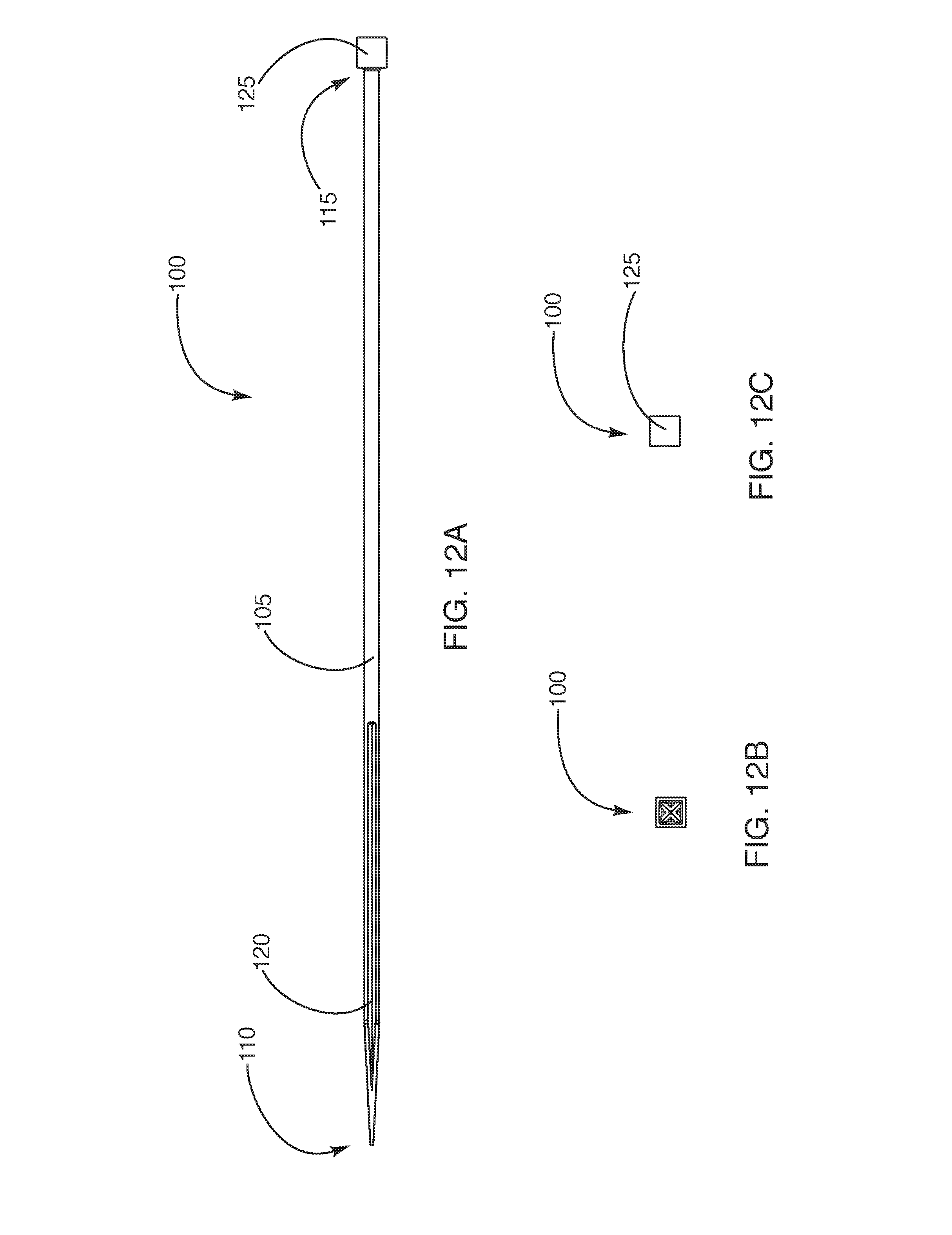
D00013
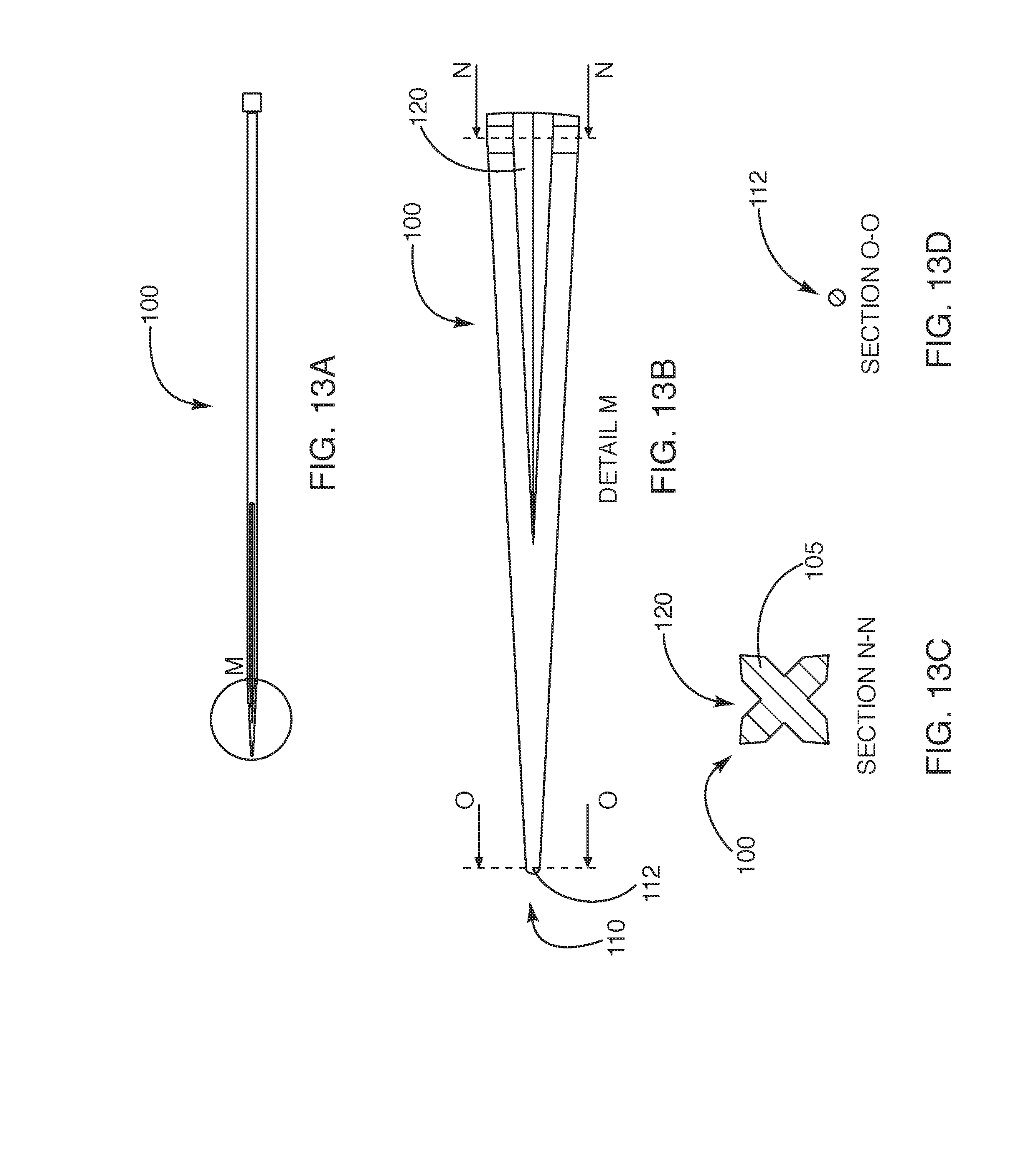
D00014
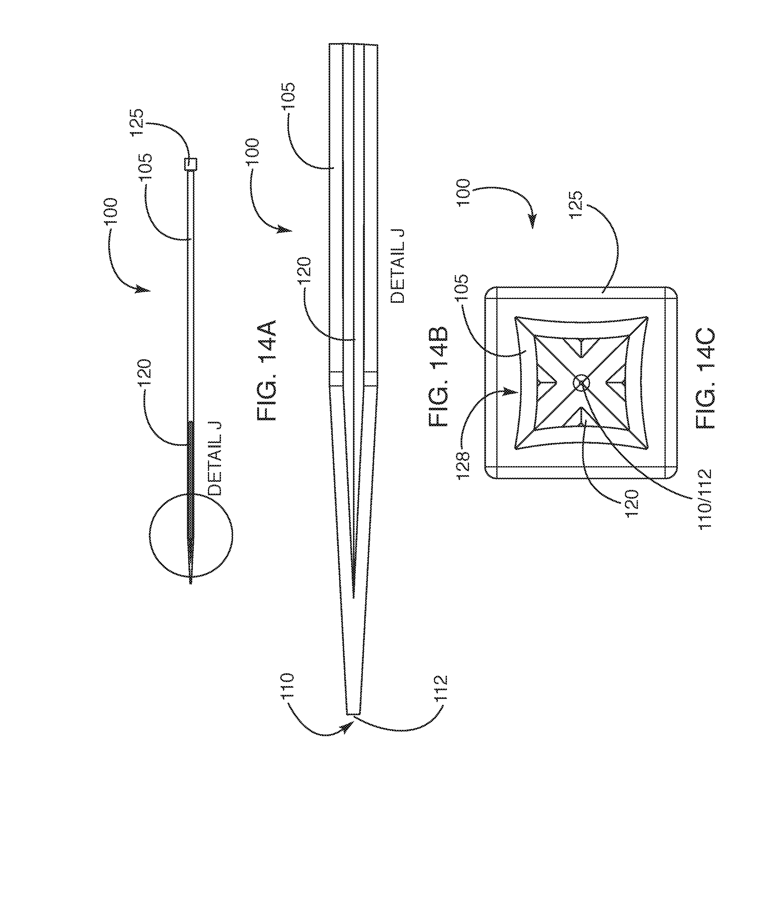
D00015

D00016
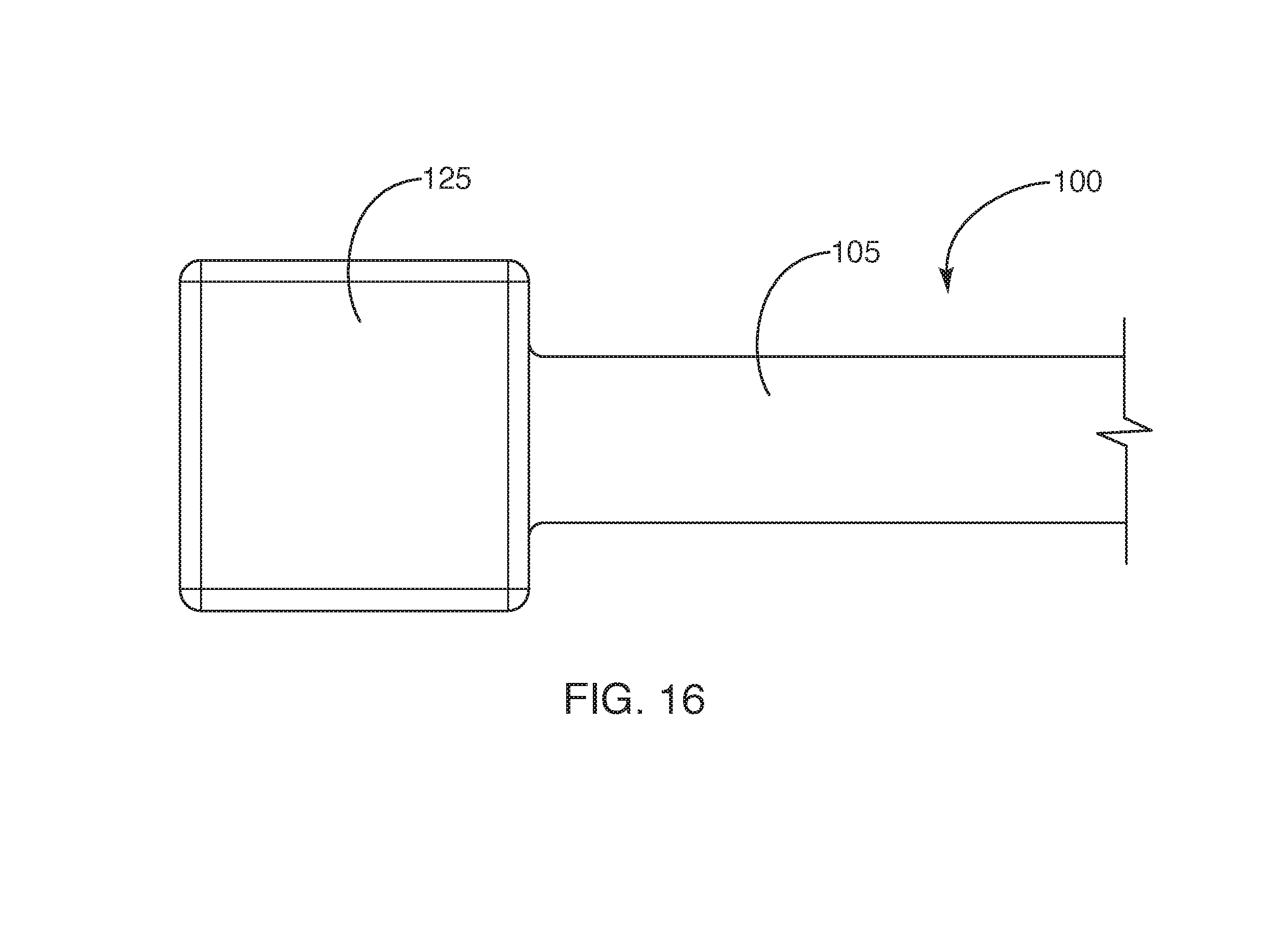
D00017

D00018

D00019

D00020
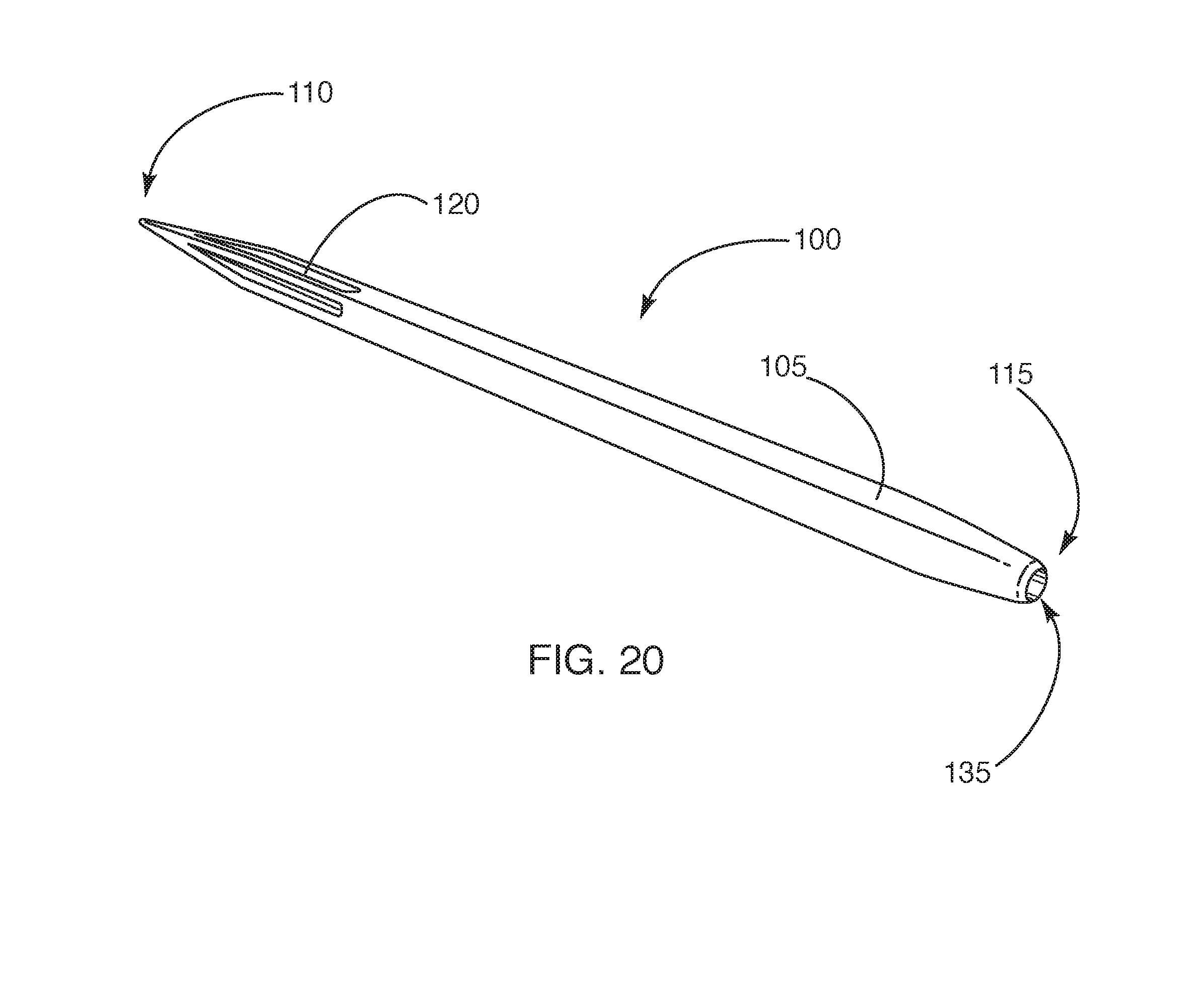
D00021

D00022

D00023
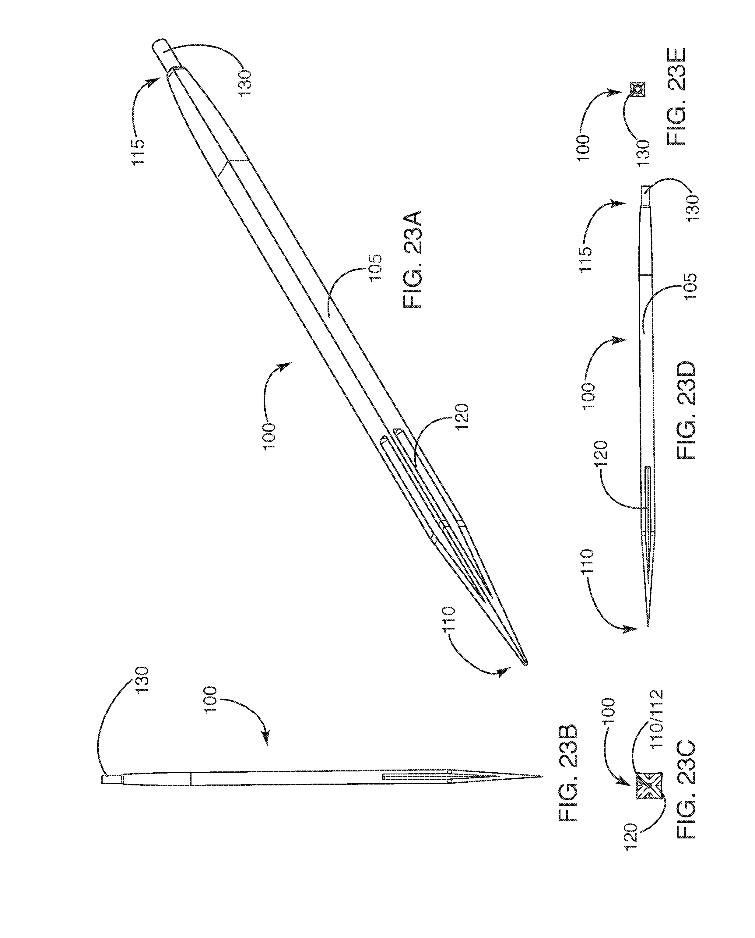
D00024

XML
uspto.report is an independent third-party trademark research tool that is not affiliated, endorsed, or sponsored by the United States Patent and Trademark Office (USPTO) or any other governmental organization. The information provided by uspto.report is based on publicly available data at the time of writing and is intended for informational purposes only.
While we strive to provide accurate and up-to-date information, we do not guarantee the accuracy, completeness, reliability, or suitability of the information displayed on this site. The use of this site is at your own risk. Any reliance you place on such information is therefore strictly at your own risk.
All official trademark data, including owner information, should be verified by visiting the official USPTO website at www.uspto.gov. This site is not intended to replace professional legal advice and should not be used as a substitute for consulting with a legal professional who is knowledgeable about trademark law.