Floating Roof for Oil Tank
Weng; Ming-Chun ; et al.
U.S. patent application number 16/148002 was filed with the patent office on 2019-04-04 for floating roof for oil tank. The applicant listed for this patent is Full Most Co., Ltd.. Invention is credited to Wen-Pin Pan, Ming-Chun Weng, Ming-Tsang Yu.
| Application Number | 20190100378 16/148002 |
| Document ID | / |
| Family ID | 63904114 |
| Filed Date | 2019-04-04 |


View All Diagrams
| United States Patent Application | 20190100378 |
| Kind Code | A1 |
| Weng; Ming-Chun ; et al. | April 4, 2019 |
Floating Roof for Oil Tank
Abstract
A floating roof for an oil tank includes a beam unit and a plurality of float units secured on the beam unit. The beam unit includes a plurality of longitudinal beams and a plurality of transverse beams. Each of the longitudinal beams has an upright wall provided with a plurality of first transverse holes. Each of the transverse beams is located between two of the longitudinal beams and has a bottom plate and two transverse side plates. Each of the two transverse side plates has a second transverse hole. The beam unit further includes a plurality of bolts each extending through one of the first transverse holes and the second transverse hole of each of the transverse side plates, and a plurality of nuts screwed onto the bolts, so that the longitudinal beams and the transverse beams are combined together.
| Inventors: | Weng; Ming-Chun; (New Taipei City, TW) ; Yu; Ming-Tsang; (New Taipei City, TW) ; Pan; Wen-Pin; (New Taipei City, TW) | ||||||||||
| Applicant: |
|
||||||||||
|---|---|---|---|---|---|---|---|---|---|---|---|
| Family ID: | 63904114 | ||||||||||
| Appl. No.: | 16/148002 | ||||||||||
| Filed: | October 1, 2018 |
| Current U.S. Class: | 1/1 |
| Current CPC Class: | B65D 88/42 20130101; B65D 88/40 20130101 |
| International Class: | B65D 88/42 20060101 B65D088/42 |
Foreign Application Data
| Date | Code | Application Number |
|---|---|---|
| Oct 3, 2017 | TW | 106134284 |
Claims
1. A floating roof for an oil tank, comprising: a beam unit; and a plurality of float units mounted on the beam unit; wherein: the beam unit includes a plurality of longitudinal beams and a plurality of transverse beams connected with the longitudinal beams; each of the longitudinal beams has an upright wall provided with a plurality of first transverse holes; each of the transverse beams is located between two of the longitudinal beams and has a bottom plate and two transverse side plates extending upward from the bottom plate; each of the two transverse side plates of each of the transverse beams is provided with a second transverse hole aligning with one of the first transverse holes of one of the longitudinal beams; the beam unit further includes a plurality of bolts each extending through one of the first transverse holes of each of the longitudinal beams and the second transverse hole of each of the two transverse side plates of each of the transverse beams, and a plurality of nuts screwed onto the bolts, so that the longitudinal beams and the transverse beams are combined together; and the float units are secured on and supported by the longitudinal beams and the transverse beams of the beam unit.
2. The floating roof for an oil tank of claim 1, wherein: each of the transverse beams has a longitudinal side plate located between the two transverse side plates; the longitudinal side plate of each of the transverse beams is provided with a plurality of longitudinal holes; and the beam unit further includes a plurality of screws respectively extending through the first transverse holes of each of the longitudinal beams and the longitudinal holes of the longitudinal side plate of each of the transverse beams and respectively screwed into a periphery of each of the float units, so that the float units are locked onto the longitudinal beams and the transverse beams of the beam unit.
3. The floating roof for an oil tank of claim 1, wherein: each of the transverse beams has two outside plates respectively extending outward from the two transverse side plates, with a slot being defined between each of the two outside plates and each of the two transverse side plates; each of the two outside plates of each of the transverse beams is provided with a third transverse hole aligning with the second transverse hole of each of the two transverse side plates; the slot of each of the transverse beams allows insertion of the upright wall of each of the longitudinal beams; each of the bolts extends through the second transverse hole of each of the two transverse side plates of each of the transverse beams, one of the first transverse holes of each of the longitudinal beams and the third transverse hole of each of the two outside plates of each of the transverse beams; and each of the nuts is screwed onto the bolts, so that the longitudinal beams and the transverse beams are combined together.
4. The floating roof for an oil tank of claim 3, wherein: each of the transverse beams has a longitudinal side plate located between the two transverse side plates; the longitudinal side plate of each of the transverse beams is provided with a plurality of longitudinal holes; and the beam unit further includes a plurality of screws respectively extending through the first transverse holes of each of the longitudinal beams and the longitudinal holes of the longitudinal side plate of each of the transverse beams and respectively screwed into a periphery of each of the float units, so that the float units are locked onto the longitudinal beams and the transverse beams of the beam unit.
5. The floating roof for an oil tank of claim 1, wherein the upright wall of each of the longitudinal beams has a lower end formed with a rib extending toward one side thereof.
6. The floating roof for an oil tank of claim 1, wherein the upright wall of each of the longitudinal beams has a lower end formed with two ribs extending toward two opposite sides thereof.
7. The floating roof for an oil tank of claim 6, wherein each of the longitudinal beams is made of a metal sheet plate which is bent to form the upright wall and the two ribs.
8. The floating roof for an oil tank of claim 6, wherein each of the longitudinal beams is made of metal material which is extruded or cast to form the upright wall and the two ribs.
Description
BACKGROUND OF THE INVENTION
1. Field of the Invention
[0001] The present invention relates to a floating-roof tank and, more particularly, to a floating roof for an oil tank.
2. Description of the Related Art
[0002] A conventional oil tank comprises a shell, a floating roof mounted in the shell, and a sealing device mounted between the shell and the floating roof. The floating roof is placed on the top of an oil contained in the shell and is lifted or lowered with the liquid level to reduce diffusion of the oil air. The floating roof includes a plurality of float units and a plurality of connections mounted between the float units to connect the float units. A conventional floating roof comprises a plurality of connecting rods and a plurality of float units. The connecting rods are arranged longitudinally and transversely to form multiple receiving spaces for mounting the float units. Each of the connecting rods has two sides each formed with at least one mounting slot allowing insertion of one of the float units. The top of each of the connecting rods is provided with at least one reinforcing plate which is provided with a plurality of locking portions. Each of the float units has a periphery provided with a plurality of fastening members. The conventional floating roof further comprises a plurality of screws extending through the locking portions of the at least one reinforcing plate of each of the connecting rods and screwed into the fastening members of each of the float units, so that the connecting rods and the float units are combined together.
BRIEF SUMMARY OF THE INVENTION
[0003] In accordance with the present invention, there is provided a floating roof for an oil tank, comprising a beam unit and a plurality of float units mounted on the beam unit. The beam unit includes a plurality of longitudinal beams and a plurality of transverse beams connected with the longitudinal beams. Each of the longitudinal beams has an upright wall provided with a plurality of first transverse holes. Each of the transverse beams is located between two of the longitudinal beams and has a bottom plate and two transverse side plates extending upward from the bottom plate. Each of the two transverse side plates of each of the transverse beams is provided with a second transverse hole aligning with one of the first transverse holes of one of the longitudinal beams. The beam unit further includes a plurality of bolts each extending through one of the first transverse holes of each of the longitudinal beams and the second transverse hole of each of the two transverse side plates of each of the transverse beams, and a plurality of nuts screwed onto the bolts, so that the longitudinal beams and the transverse beams are combined together. The float units are secured on and supported by the longitudinal beams and the transverse beams of the beam unit.
[0004] Further benefits and advantages of the present invention will become apparent after a careful reading of the detailed description with appropriate reference to the accompanying drawings.
BRIEF DESCRIPTION OF THE SEVERAL VIEWS OF THE DRAWING(S)
[0005] FIG. 1 is a plane view of an oil tank in accordance with the preferred embodiment of the present invention.
[0006] FIG. 2 is a partially exploded perspective view of a floating roof in accordance with the preferred embodiment of the present invention.
[0007] FIG. 2A is a locally enlarged view of the floating roof taken along marking 2A as shown in FIG. 2.
[0008] FIG. 3 is a partially perspective assembly view of the floating roof in accordance with the preferred embodiment of the present invention.
[0009] FIG. 4 is a perspective assembly view of the floating roof in accordance with the preferred embodiment of the present invention.
[0010] FIG. 5 is a bottom perspective view of the floating roof as shown in FIG. 4.
[0011] FIGS. 6-9 are perspective views showing transverse beams of different types in accordance with the preferred embodiment of the present invention.
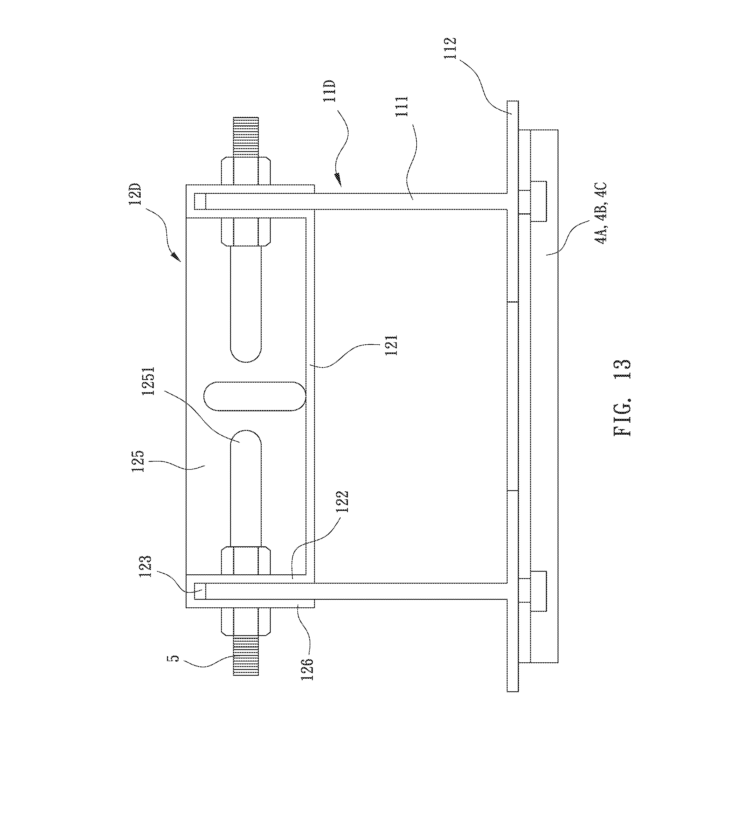
[0012] FIGS. 10-13 are schematic plane views showing combination of transverse beams with longitudinal beams of different types in accordance with the preferred embodiment of the present invention.
[0013] FIGS. 14-16 are perspective views showing fixed seats of different types in accordance with the preferred embodiment of the present invention.
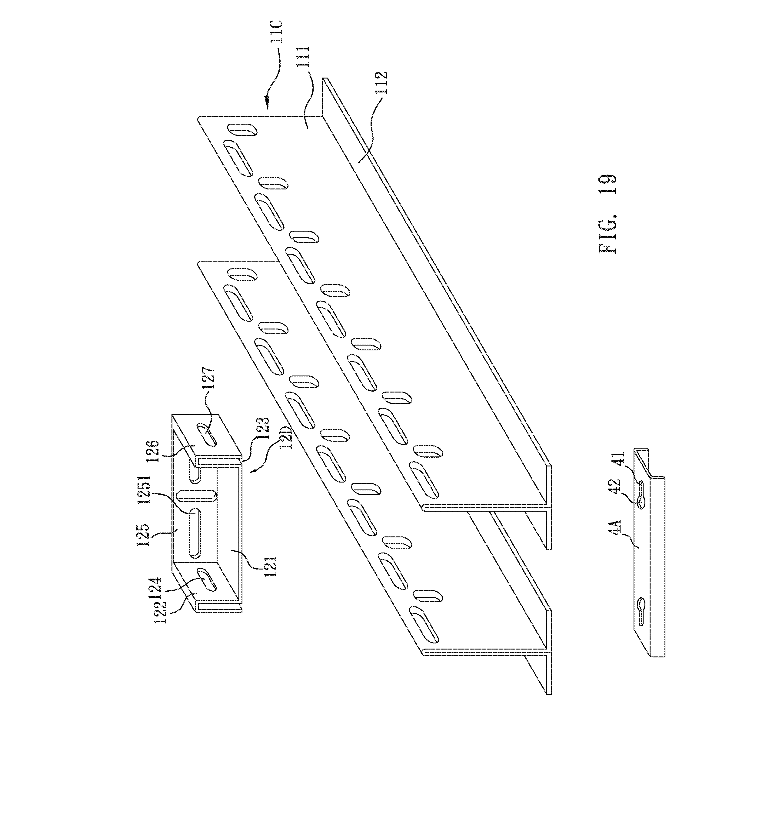
[0014] FIGS. 17-20 are exploded perspective views showing combination of transverse beams with longitudinal beams of different types in accordance with the preferred embodiment of the present invention.
DETAILED DESCRIPTION OF THE INVENTION
[0015] Referring to the drawings and initially to FIG. 1, an oil tank in accordance with the preferred embodiment of the present invention comprises a shell A, a floating roof mounted in the shell A, and a sealing device B mounted between an inner wall of the shell A and an outer diameter of the floating roof. The floating roof is placed on the top of an oil contained in the shell A and is lifted or lowered with the liquid level to reduce diffusion of the oil air.
[0016] Referring now to FIGS. 2-5 with reference to FIG. 1, the floating roof in accordance with the preferred embodiment of the present invention comprises a beam unit 1, a plurality of float units 2 mounted on the beam unit 1, and a plurality of support posts 3 mounted on the beam unit 1.
[0017] The beam unit 1 includes a plurality of longitudinal beams 11 and a plurality of transverse beams 12 connected with the longitudinal beams 11.
[0018] The longitudinal beams 11 are parallel with each other. Each of the longitudinal beams 11 is made of metallic material and is formed to have an elongate shape. Each of the longitudinal beams 11 has an upright wall 111 provided with a plurality of first transverse holes 1110 (see FIG. 2A) each extending in a lengthwise direction of each of the longitudinal beams 11. Each of the first transverse holes 1110 has different shapes, such as circular or elongate shapes.
[0019] The transverse beams 12 are parallel with each other and perpendicular to the longitudinal beams 11. Each of the transverse beams 12 is located between two of the longitudinal beams 11 and has a bottom plate 121 and two transverse side plates 122 extending upward from the bottom plate 121. Each of the two transverse side plates 122 of each of the transverse beams 12 is provided with a second transverse hole 124 (see FIG. 2A) aligning with one of the first transverse holes 1110 of one of the longitudinal beams 11.
[0020] The beam unit 1 further includes a plurality of bolts 5 (see FIG. 10) each extending through one of the first transverse holes 1110 of each of the longitudinal beams 11 and the second transverse hole 124 of each of the two transverse side plates 122 of each of the transverse beams 12, and a plurality of nuts screwed onto the bolts 5, so that the longitudinal beams 11 and the transverse beams 12 are combined together.
[0021] The beam unit 1 further includes a plurality of reinforcing members 13 each mounted on a connection of each of the longitudinal beams 11 and each of the transverse beams 12 to reinforce the whole strength of the beam unit 1.
[0022] The float units 2 are secured on and supported by the longitudinal beams 11 and the transverse beams 12 of the beam unit 1. The longitudinal beams 11 and the transverse beams 12 of the beam unit 1 construct multiple receiving spaces of different sizes for mounting the float units 2 of different sizes.
[0023] The support posts 3 are mounted on the bottom of the beam unit 1. Each of the support posts 3 has an upper end provided with a support plate 31 locked onto the beam unit 1 by screws, so that each of the support posts 3 is affixed to the bottom of the beam unit 1. Thus, when the floating roof is lowered, the support posts 3 are moved downward to touch the bottom of the shell A to keep a determined space between the floating roof and the bottom of the shell A.
[0024] Referring to FIG. 6, each of the transverse beams 12A has a substantially U-shaped configuration.
[0025] Referring to FIG. 7 with reference to FIGS. 2 and 2A, each of the transverse beams 12B has a longitudinal side plate 125 located between the two transverse side plates 122. The longitudinal side plate 125 of each of the transverse beams 12B is provided with a plurality of longitudinal holes 1251. The beam unit 1 further includes a plurality of screws respectively extending through the first transverse holes 1110 of each of the longitudinal beams 11 and the longitudinal holes 1251 of the longitudinal side plate 125 of each of the transverse beams 12B and respectively screwed into a periphery of each of the float units 2, so that the float units 2 are locked onto the longitudinal beams 11 and the transverse beams 12B of the beam unit 1.
[0026] Referring to FIG. 8 with reference to FIGS. 2 and 2A, each of the transverse beams 12C has two outside plates 126 respectively extending outward from the two transverse side plates 122, with a slot 123 being defined between each of the two outside plates 126 and each of the two transverse side plates 122. Each of the two outside plates 126 of each of the transverse beams 12C is provided with a third transverse hole 127 aligning with the second transverse hole 124 of each of the two transverse side plates 122. The slot 123 of each of the transverse beams 12C allows insertion of the upright wall 111 of each of the longitudinal beams 11. Each of the bolts 5 (see FIG. 10) extends through the second transverse hole 124 of each of the two transverse side plates 122 of each of the transverse beams 12C, one of the first transverse holes 1110 of each of the longitudinal beams 11 and the third transverse hole 127 of each of the two outside plates 126 of each of the transverse beams 12C, and each of the nuts is screwed onto the bolts 5, so that the longitudinal beams 11 and the transverse beams 12C are combined together.
[0027] Referring to FIG. 9 with reference to FIGS. 7 and 8, each of the transverse beams 12D is a combination of each of the transverse beams 12B and each of the transverse beams 12C.
[0028] Referring to FIG. 10, the upright wall 111 of each of the longitudinal beams 11A has a lower end formed with a rib 112 extending toward one side thereof.
[0029] Referring to FIG. 11, the upright wall 111 of each of the longitudinal beams 11B does not have any rib.
[0030] Referring to FIG. 12, the upright wall 111 of each of the longitudinal beams 11C has a lower end formed with two ribs 112 extending toward two opposite sides thereof. Preferably, each of the longitudinal beams 11C is made of a metal sheet plate which is bent to form the upright wall 111 and the two ribs 112.
[0031] Referring to FIG. 13, the upright wall 111 of each of the longitudinal beams 11D has a lower end formed with two ribs 112 extending toward two opposite sides thereof. Preferably, each of the longitudinal beams 11D is made of metal material which is extruded or cast to form the upright wall 111 and the two ribs 112.
[0032] As shown in FIGS. 10-13, the longitudinal beams 11A, 11B, 11C or 11D are connected with the transverse beams 12D for example.
[0033] Referring to FIG. 14 with reference to FIG. 2, the floating roof further comprises a plurality of fixed seats 4A located under the longitudinal beams 11. Each of the fixed seats 4A has a surface provided with a plurality of locking slots. Each of the locking slots has a first end provided with a groove 41 and a second end provided with an enlarged hole 42 connected to the groove 41. The enlarged hole 42 has a diameter greater than the width of the groove 41. Preferably, each of the fixed seats 4A has a substantially inverted U-shaped configuration.
[0034] Referring to FIG. 15, each of the fixed seats 4B has a substantially inverted L-shaped configuration.
[0035] Referring to FIG. 16, each of the fixed seats 4C is a sheet plate.
[0036] Referring to FIG. 17, the fixed seats 4A are located under the longitudinal beams 11A. The rib 112 of each of the longitudinal beams 11A is provided with a screw hole (not shown). The floating roof further comprises a plurality of screws each screwed into the screw hole of the rib 112 of each of the longitudinal beams 11A and each extending through the enlarged hole 42 into the groove 41 of each of the fixed seats 4A, so that the longitudinal beams 11A are locked onto the fixed seats 4A.
[0037] As shown in FIGS. 17-20, the longitudinal beams 11A, 11B, 11C or 11D are connected with the transverse beams 12D for example. In addition, the longitudinal beams 11A, 11B, 11C or 11D are connected with the fixed seats 4A for example.
[0038] Again referring to FIGS. 10-13, the longitudinal beams 11A, 11B, 11C or 11D are connected with the fixed seats 4A, 4B or 4C.
[0039] Accordingly, the longitudinal beams 11 and the transverse beams 12 are combined to construct the beam unit 1 which locks and supports the float units 2, so that the floating roof has a simplified structure, thereby decreasing the cost of fabrication. In addition, the longitudinal beams 11 and the transverse beams 12 are assembled solidly and steadily, so that the beam unit 1 has a greater mechanic strength, thereby enhancing the lifetime of the floating roof. Further, the longitudinal beams 11 and the transverse beams 12 are assembled easily and conveniently, thereby facilitating the operator assembling the beam unit 1.
[0040] Although the invention has been explained in relation to its preferred embodiment(s) as mentioned above, it is to be understood that many other possible modifications and variations can be made without departing from the scope of the present invention. It is, therefore, contemplated that the appended claim or claims will cover such modifications and variations that fall within the scope of the invention.
* * * * *
D00000
D00001
D00002
D00003
D00004
D00005
D00006
D00007
D00008
D00009
D00010
D00011
D00012

D00013

D00014
D00015

D00016

D00017

D00018
D00019

XML
uspto.report is an independent third-party trademark research tool that is not affiliated, endorsed, or sponsored by the United States Patent and Trademark Office (USPTO) or any other governmental organization. The information provided by uspto.report is based on publicly available data at the time of writing and is intended for informational purposes only.
While we strive to provide accurate and up-to-date information, we do not guarantee the accuracy, completeness, reliability, or suitability of the information displayed on this site. The use of this site is at your own risk. Any reliance you place on such information is therefore strictly at your own risk.
All official trademark data, including owner information, should be verified by visiting the official USPTO website at www.uspto.gov. This site is not intended to replace professional legal advice and should not be used as a substitute for consulting with a legal professional who is knowledgeable about trademark law.