A Path Following Arrangement Having A Catenary Structure And A Method For Operating Such An Arrangement
CIEMIEWICZ; Alec ; et al.
U.S. patent application number 16/095059 was filed with the patent office on 2019-04-04 for a path following arrangement having a catenary structure and a method for operating such an arrangement. The applicant listed for this patent is TAIT TOWERS MANUFACTURING, LLC. Invention is credited to Alec CIEMIEWICZ, Adam DAVIS, Leonard Ryan HEWLETT, Benjamin WHITE, Adam YEAGER.
| Application Number | 20190100220 16/095059 |
| Document ID | / |
| Family ID | 58633115 |
| Filed Date | 2019-04-04 |


View All Diagrams
| United States Patent Application | 20190100220 |
| Kind Code | A1 |
| CIEMIEWICZ; Alec ; et al. | April 4, 2019 |
A PATH FOLLOWING ARRANGEMENT HAVING A CATENARY STRUCTURE AND A METHOD FOR OPERATING SUCH AN ARRANGEMENT
Abstract
There is provided to a path following arrangement having a catenary structure and a method for operating such an arrangement. The path following arrangement permits a ride participant or a passenger to traverse tracts of land having a relatively wide range of scenic variety in that the path of travel can include linear portions and non-linear (change of direction) portions.
| Inventors: | CIEMIEWICZ; Alec; (Sinking Spring, PA) ; DAVIS; Adam; (Leola, PA) ; HEWLETT; Leonard Ryan; (Lancaster, PA) ; WHITE; Benjamin; (Lititz, PA) ; YEAGER; Adam; (Lancaster, PA) | ||||||||||
| Applicant: |
|
||||||||||
|---|---|---|---|---|---|---|---|---|---|---|---|
| Family ID: | 58633115 | ||||||||||
| Appl. No.: | 16/095059 | ||||||||||
| Filed: | April 12, 2017 | ||||||||||
| PCT Filed: | April 12, 2017 | ||||||||||
| PCT NO: | PCT/US2017/027226 | ||||||||||
| 371 Date: | October 19, 2018 |
Related U.S. Patent Documents
| Application Number | Filing Date | Patent Number | ||
|---|---|---|---|---|
| 62325150 | Apr 20, 2016 | |||
| Current U.S. Class: | 1/1 |
| Current CPC Class: | B61B 12/026 20130101; B61B 7/06 20130101; A63G 21/22 20130101; B61B 7/00 20130101 |
| International Class: | B61B 12/02 20060101 B61B012/02; B61B 7/00 20060101 B61B007/00; A63G 21/22 20060101 A63G021/22 |
Claims
1. A path following arrangement comprising: a first carriage; and a catenary structure having a travel path assembly delimiting a course along which the first carriage can travel while supported at a spacing from a reference surface and the travel path assembly including a first change of direction run having an entry and an exit, the first carriage having an engagement element operable to engage the travel path assembly in a manner that permits the first carriage to move relatively along the travel path assembly while being guided thereby and the first carriage being movable relatively along the travel path assembly in a travel direction such that the first carriage initially enters the first change of direction run via the entry thereof and thereafter exits the first change of direction run via the exit thereof during each passage of the first carriage along the first change of direction run, and the catenary structure including an upstream anchor location, a downstream anchor location, and an intermediate tie-in element, the upstream anchor location engaging a portion of the travel path assembly and the upstream anchor location and the intermediate tie-in element cooperating with one another to maintain the travel path assembly in a supported disposition such that the first carriage can travel along the course upstream of the first change of direction run, relative to the travel direction, while supported at a spacing from the reference surface and the downstream anchor location engaging a portion of the travel path assembly and the intermediate tie-in element and the downstream anchor location cooperating with one another to maintain the travel path assembly in a supported disposition such that the first carriage can continue to travel along the course while supported at a spacing from the reference surface after the first carriage has exited the first change of direction run, the entry and the exit of the first change of direction run delimiting an arc of a reference circle, the arc having a tangent, the travel path assembly and the intermediate tie-in element being operatively interconnected such that the first change of direction run of the travel path assembly can be restorably displaced, in a displacement direction perpendicular to the tangent of the arc delimited by first change of direction run of the travel path assembly, from a home disposition to a temporary displacement disposition in response to the application of a force on the travel path assembly during the travel of the first carriage along the first change of direction run and can be restored to its home disposition from its temporary displacement disposition.
2. The path following arrangement according to claim 1, wherein the travel path assembly that supports the first carriage and at least a second carriage at a vertical spacing from a reference surface and the first carriage and the second carriage are each configured to carry one or more persons, a cargo load comprised of no persons, or a combination of one or more persons and a cargo load.
3. The path following arrangement according to claim 1, wherein the first carriage and the second carriage each include a motive device supported for travel with the carriage and operable to move the carriage relative to a travel path assembly of a catenary structure, independently or in coordination with the movement of other carriages.
4. A path following arrangement comprising: a first carriage; and a catenary structure, a catenary structure having a travel path assembly delimiting a course along which the first carriage can travel while supported at a spacing from a reference surface and the travel path assembly including a first change of direction run having an entry and an exit, the first carriage having an engagement element operable to engage the travel path assembly in a manner that permits the first carriage to move relatively along the travel path assembly while being guided thereby and the first carriage being movable relatively along the travel path assembly in a travel direction such that the first carriage initially enters the first change of direction run via the entry thereof and thereafter exits the first change of direction run via the exit thereof during each passage of the first carriage along the first change of direction run, and the catenary structure including an upstream anchor location, a downstream anchor location, and an intermediate tie-in element, the upstream anchor location engaging a portion of the travel path assembly and the upstream anchor location and the intermediate tie-in element cooperating with one another to maintain the travel path assembly in a supported disposition such that the first carriage can travel along the course upstream of the first change of direction run, relative to the travel direction, while supported at a spacing from the reference surface, and the downstream anchor location engaging a portion of the travel path assembly and the intermediate tie-in element and the downstream anchor location cooperating with one another to maintain the travel path assembly in a supported disposition such that the first carriage can continue to travel along the course while supported at a spacing from the reference surface after the first carriage has exited the first change of direction run, the entry and the exit of the first change of direction run delimiting an arc of a reference circle, the arc having a tangent, the intermediate tie-in element having an upstream end and a downstream end and the upstream end of the intermediate tie-in element and the entry location of the first change of direction run of the travel path assembly being at a predetermined spacing from one another in a base disposition, and the intermediate tie-in element and the travel path assembly being movable relative to one another such that the travel path assembly and the intermediate tie-in element can be restorably displaced from the base disposition in which the upstream end of the intermediate tie-in element and the entry location of the first change of direction run of the travel path assembly are at a predetermined spacing from one another to an offset disposition in which the upstream end of the intermediate tie-in element and the entry location of the first change of direction run of the travel path assembly have moved relative to one another in response to the application of a force on the travel path assembly, wherein the upstream end of the intermediate tie-in element and the entry location of the first change of direction run of the travel path assembly are at an offset spacing from one another that is different than the predetermined spacing from one another in the base disposition, and the intermediate tie-in element and the travel path assembly being operable to be returned to their base disposition from their offset disposition.
5. A path following arrangement comprising: a first carriage; and a catenary structure having a travel path assembly delimiting a course along which the first carriage can travel while supported at a spacing from a reference surface and the travel path assembly including a first change of direction run having an entry and an exit, the first carriage having an engagement element operable to engage the travel path assembly in a manner that permits the first carriage to move relatively along the travel path assembly while being guided thereby and the first carriage being movable relatively along the travel path assembly in a travel direction such that the first carriage initially enters the first change of direction run via the entry thereof and thereafter exits the first change of direction run via the exit thereof during each passage of the first carriage along the first change of direction run, and the catenary structure including an upstream anchor location, a downstream anchor location, and an intermediate tie-in element, the upstream anchor location engaging a portion of the travel path assembly and the upstream anchor location and the intermediate tie-in element cooperating with one another to maintain the travel path assembly in a supported disposition such that the first carriage can travel along the course upstream of the first change of direction run, relative to the travel direction, while supported at a spacing from the reference surface, and the downstream anchor location engaging a portion of the travel path assembly and the intermediate tie-in element and the downstream anchor location cooperating with one another to maintain the travel path assembly in a supported disposition such that the first carriage can continue to travel along the course while supported at a spacing from the reference surface after the first carriage has exited the first change of direction run, the entry and the exit of the first change of direction run delimiting an arc of a reference circle, the arc having a tangent, and the travel path assembly and the intermediate tie-in element being operatively interconnected such that the first change of direction run of the travel path assembly can be restorably displaced, in a displacement direction perpendicular to the tangent of the arc delimited by first change of direction run of the travel path assembly, from a home disposition to a temporary displacement disposition in response to the application of a force on the travel path assembly during the travel of the first carriage along the first change of direction run and can be restored to its home disposition from its temporary displacement disposition the intermediate tie-in element having an upstream end and a downstream end and the upstream end of the intermediate tie-in element and the entry location of the first change of direction run of the travel path assembly being at a predetermined spacing from one another in a base disposition, and the intermediate tie-in element and the travel path assembly being movable relative to one another such that the travel path assembly and the intermediate tie-in element can be restorably displaced from the base disposition in which the upstream end of the intermediate tie-in element and the entry location of the first change of direction run of the travel path assembly are at a predetermined spacing from one another to an offset disposition in which the upstream end of the intermediate tie-in element and the entry location of the first change of direction run of the travel path assembly have moved relative to one another in response to the application of a force on the travel path assembly, wherein the upstream end of the intermediate tie-in element and the entry location of the first change of direction run of the travel path assembly are at an offset spacing from one another that is different than the predetermined spacing from one another in the base disposition, and the intermediate tie-in element and the travel path assembly being operable to be returned to their base disposition from their offset disposition.
Description
FIELD OF THE INVENTION
[0001] The present disclosure relates to a path following arrangement having a catenary structure and a method for operating such an arrangement.
BACKGROUND OF THE INVENTION
[0002] U.S. Published Patent Application No. 2002/162,477 to Palumbo notes that, since 1968, ziplines utilized in challenge/ropes course facilities have typically consisted of a steel cable, of at least three-eighths of an inch diameter, rigged between two points of differing elevation with a single-wheel pulley attached to the cable. Initially, for ascend and descend movements, the participant was hung by a lanyard attached to the pulley. Later, this method of attachment was replaced by the participant being secured in some type of harness being suspended from the pulley. In both cases, the participant climbed to a disembarkation point, and, after "zipping" down the cable, was manually removed at the terminus of the system.
[0003] U.S. Pat. No. 6,622,634 to Cylvick discloses that suspended cable systems of various types are known in the prior art and notes that U.S. Pat. No. 5,224,425 to Remington is directed to a cable skydiving apparatus in which a rider on a pulley block car descends a mountainside along a catenary cable and generally comes to a stop as the result of frictional forces, before hitting the lower cable support point.
[0004] U.S. Pat. No. 8,746,149 to Elhard discloses a zipline arrangement via which a ride participant supported on a trolley can traverse a path from a higher elevation to a lower elevation. According to this document, the zipline arrangement makes it possible for the ride participants to avoid a large tree that would otherwise block the path.
[0005] While designs for catenary arrangements have been proposed that permit avoiding obstacles that would otherwise block the path of travel, there is still a need for a path following arrangement that permits a ride participant or passenger to traverse tracts of land having a relatively wide range of scenic variety, wherein the path of travel includes linear portions and non-linear (change of direction) portions, and wherein the travel of the ride participant or passenger through the non-linear (change of direction) portions is smooth and reliable.
BRIEF DESCRIPTION OF THE INVENTION
[0006] One object of the present invention is to provide a path following arrangement that permits a ride participant or passenger to traverse tracts of land having a relatively wide range of scenic variety, wherein the path of travel includes linear portions and non-linear (change of direction) portions, and wherein the travel of the ride participant or passenger through the non-linear (change of direction) portions is smooth and reliable.
[0007] One aspect of the present invention relates to a path following arrangement.
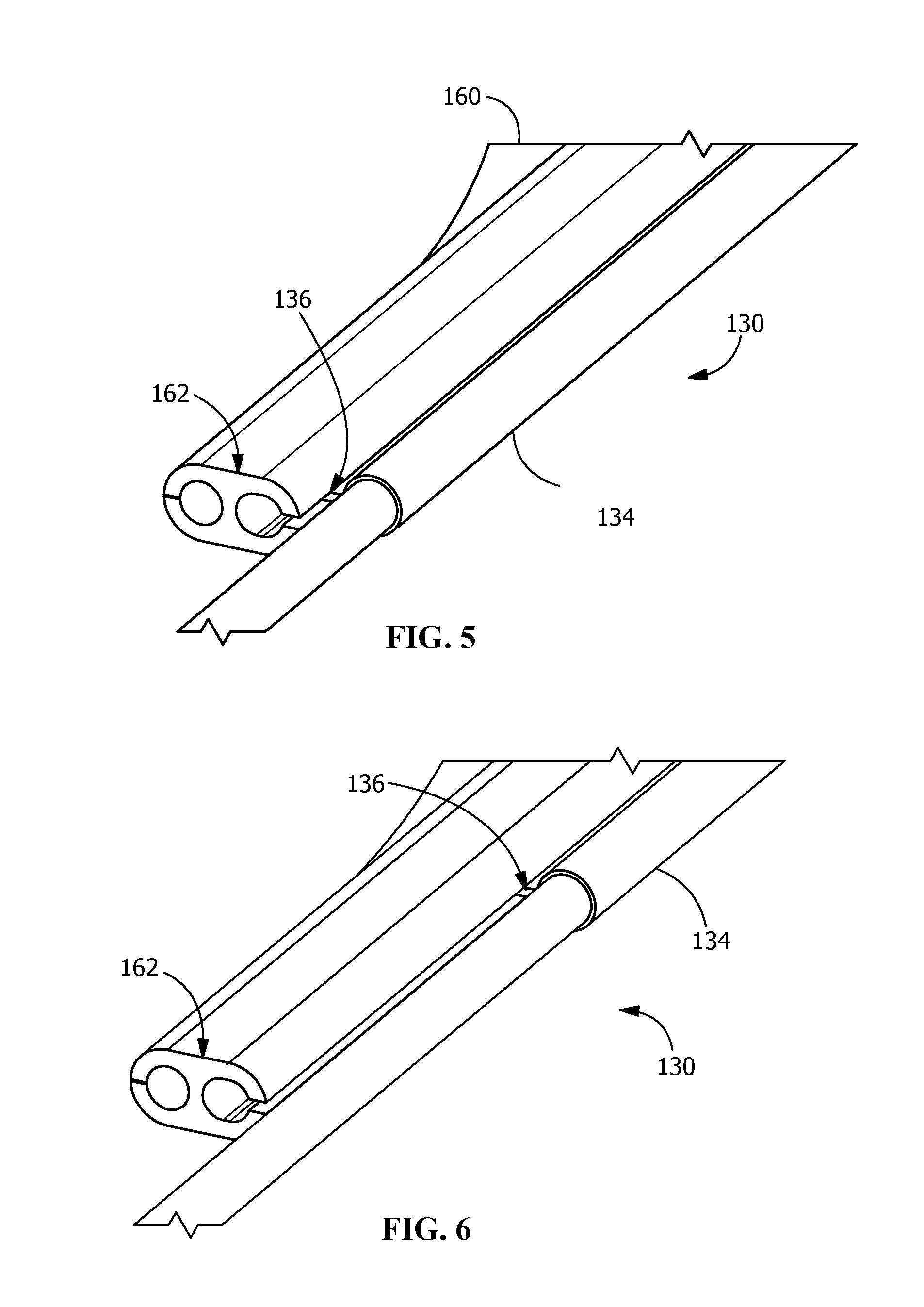
[0008] According to one feature of the one aspect of the present invention, the path following arrangement permits a ride participant or passenger to traverse tracts of land having a relatively wide range of scenic variety in that the path of travel can include linear portions and non-linear (change of direction) portions.
[0009] An advantage of the one aspect of the present invention is that the path following arrangement of the present disclosure enables the ride participant to control and select the speed and acceleration of the path following platform. Additionally, the ride participant can comfortably enter into, and exit from, non-linear (change of direction) portions of the path.
[0010] According to one embodiment of the one aspect of the present invention, the path following arrangement includes a first carriage and a catenary structure. The catenary structure has a travel path assembly delimiting a course along which the first carriage can travel while supported at a spacing from a reference surface and the travel path assembly including a first change of direction run having an entry and an exit. The first carriage has an engagement element operable to engage the travel path assembly in a manner that permits the first carriage to move relatively along the travel path assembly while being guided thereby and the first carriage being movable relatively along the travel path assembly in a travel direction such that the first carriage initially enters the first change of direction run via the entry thereof and thereafter exits the first change of direction run via the exit thereof during each passage of the first carriage along the first change of direction run.
[0011] Additionally, the catenary structure includes an upstream anchor location, a downstream anchor location, and an intermediate tie-in element, the upstream anchor location engaging a portion of the travel path assembly and the upstream anchor location and the intermediate tie-in element cooperating with one another to maintain the travel path assembly in a supported disposition such that the first carriage can travel along the course upstream of the first change of direction run, relative to the travel direction, while supported at a spacing from the reference surface. Moreover, the downstream anchor location engages a portion of the travel path assembly and the intermediate tie-in element and the downstream anchor location cooperate with one another to maintain the travel path assembly in a supported disposition such that the first carriage can continue to travel along the course while supported at a spacing from the reference surface after the first carriage has exited the first change of direction run.
[0012] According to further features of the one embodiment of the one aspect of the present invention, the entry and the exit of the first change of direction run delimit an arc of a reference circle, the arc having a tangent. The travel path assembly and the intermediate tie-in element are operatively interconnected such that the first change of direction run of the travel path assembly can be restorably displaced, in a displacement direction perpendicular to the tangent of the arc delimited by first change of direction run of the travel path assembly, from a home disposition to a temporary displacement disposition in response to the application of a force on the travel path assembly during the travel of the first carriage along the first change of direction run and can be restored to its home disposition from its temporary displacement disposition. Additionally, according to further additional features of the one embodiment of the one aspect of the present invention, the intermediate tie-in element has an upstream end and a downstream end and the upstream end of the intermediate tie-in element and the entry location of the first change of direction run of the travel path assembly are at a predetermined spacing from one another in a base disposition. The intermediate tie-in element and the travel path assembly are movable relative to one another such that the travel path assembly and the intermediate tie-in element can be restorably displaced from the base disposition in which the upstream end of the intermediate tie-in element and the entry location of the first change of direction run of the travel path assembly are at a predetermined spacing from one another to an offset disposition in which the upstream end of the intermediate tie-in element and the entry location of the first change of direction run of the travel path assembly have moved relative to one another in response to the application of a force on the travel path assembly, wherein the upstream end of the intermediate tie-in element and the entry location of the first change of direction run of the travel path assembly are at an offset spacing from one another that is different than the predetermined spacing from one another in the base disposition. The intermediate tie-in element and the travel path assembly are operable to be returned to their base disposition from their offset disposition.
[0013] Further aspects of the present invention are disclosed herein. The features as discussed above, as well as other features and advantages of the present disclosure, will be appreciated and understood by those skilled in the art from the following detailed description and drawings.
BRIEF DESCRIPTION OF THE DRAWINGS
[0014] FIG. 1 is a schematic top perspective view of one embodiment of the path following arrangement of the present invention.
[0015] FIG. 2 is an enlarged top perspective view of a portion of the path following arrangement shown in FIG. 1.
[0016] FIG. 3 is an enlarged top perspective view of a portion of the one embodiment of the path following arrangement of the present invention shown in FIG. 1.
[0017] FIG. 4 is a top schematic plan view of an instantaneous position of the first carriage along the first change of direction run of the travel path assembly.
[0018] FIG. 5 is an enlarged top perspective view of a portion of the first change of direction run of the travel path assembly and the flexible cable.
[0019] FIG. 6 is an enlarged top perspective view of a portion of the first change of direction run of the travel path assembly and the flexible cable.
[0020] FIG. 7 is an enlarged top perspective view of a portion of the textile sheet and the travel path assembly adjacent the entry location of the first change of direction run of the travel path assembly.
[0021] FIG. 8 is an enlarged sectional top perspective view of a portion of the textile sheet.
[0022] FIG. 9 is an enlarged sectional top perspective view of a portion of the textile sheet and the travel path assembly adjacent the entry location of the first change of direction run of the travel path assembly.
[0023] FIG. 10 is a schematic top perspective view of the textile sheet and the travel path assembly.
[0024] FIG. 11 is an enlarged schematic view of an alternative arrangement of a portion of the buffer element.
[0025] FIG. 12 is an enlarged schematic side view of a portion of the first change of direction run of the travel path assembly of the one embodiment of the path following arrangement of the present invention showing the first carriage.
[0026] FIG. 13 is an enlarged top perspective view of a portion of the first carriage and a portion of the first change of direction run of the travel path assembly of the one embodiment of the path following arrangement of the present invention.
[0027] FIG. 14 is a front enlarged schematic view of a variation of the intermediate tie-in element of the one embodiment of the path following arrangement of the present invention.
[0028] FIG. 15 is a top schematic perspective view of an additional embodiment of the path following arrangement of the present invention.
[0029] FIG. 16 is a top enlarged perspective view of a portion of the one embodiment of the path following arrangement of the present invention shown in FIG. 1.
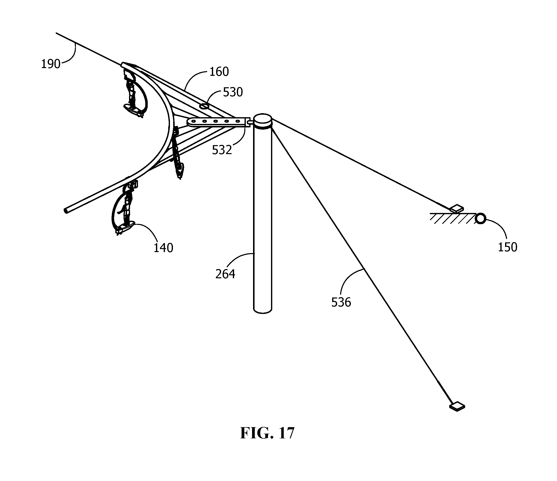
[0030] FIG. 17 is a top perspective view of a portion of a further variation of the one embodiment of the path following arrangement of the present invention shown in FIG. 1.
[0031] Wherever possible, the same reference numbers will be used throughout the drawings to represent the same parts.
DETAILED DESCRIPTION OF THE INVENTION
[0032] In the following description, numerous specific details are set forth in order to provide a more thorough description of the present invention. It will be apparent, however, to one skilled in the art, that the present invention may be practiced without these specific details. In other instances, well-known features have not been described in detail so as not to obscure the invention.
[0033] The present invention provides, in one aspect thereof, a path following arrangement having a catenary structure.
[0034] The present invention provides, in another aspect thereof, a method for operating a path following arrangement having a catenary structure.
[0035] As seen in FIG. 1, which is a schematic top perspective view of one embodiment of the path following arrangement of the present invention, a path following arrangement 110 includes a catenary structure 120 having a travel path assembly 130 along which a first carriage 140 can travel while supported at a spacing from a reference surface 150 during such travel. For example, as seen in more detail in FIG. 2, which is an enlarged top perspective view of a portion of the path following arrangement 110 shown in FIG. 1, a first carriage 140 is configured to travel in a complete loop around a course delimited by the travel path assembly 130, which is comprised of sections or portions having varying elevations and curved or linear extents. The first carriage 140 is supported at a spacing from the reference surface 150 during such travel, the reference surface 150 being exemplarily shown as a ground or terrain surface.
[0036] As used herein, the term "catenary structure" is intended to refer to a structure that includes a travel path assembly along which one or a plurality of carriages can travel while supported by the travel path assembly and the travel path assembly supports the one or more carriages at a spacing from a reference surface during such travel. The term "catenary structure" thus comprises a structure including a travel path assembly that supports one or more carriages at a vertical spacing from a reference surface and a structure including a travel path assembly that supports one or more carriages at a horizontal spacing from a reference surface.
[0037] As used herein, the term "carriage" is intended to refer to an element that is capable of being moved relative to a travel path assembly of a catenary structure. A carriage may be configured to carry one or more persons, a cargo load comprised of no persons, or a combination of one or more persons and a cargo load. A carriage may comprise a motive device supported for travel with the carriage and operable to move the carriage relative to a travel path assembly of a catenary structure, independently or in coordination with the movement of other carriages, and a carriage may alternatively be driven via a motive device having a portion that is not supported for travel with the carriage.
[0038] The travel path assembly 130 includes a first curve run 134 having an entry 136 and an exit 138. The first carriage 140 has an engagement element 142 operable to engage the travel path assembly 130 in a manner that permits the first carriage 140 to move relatively along the travel path assembly 130 while being guided thereby and the first carriage 140 is movable relatively along the travel path assembly 130 in a travel direction such that the first carriage 140 initially enters the first curve run 134 via the entry 136 thereof and thereafter exits the first curve run 134 via the exit 138 thereof during each passage of the first carriage 140 along the first curve run 134.
[0039] The catenary structure 110 includes an upstream anchor location 112, a downstream anchor location 114, and an intermediate tie-in element 180. With further reference to FIG. 2 and with reference to FIG. 3, which is an enlarged top perspective view of a portion of the one embodiment of the path following arrangement of the present invention shown in FIG. 2, in connection with the one embodiment of the path following arrangement of the present invention, the catenary structure 120 includes a plurality of vertical posts 262, 264, 266, 268, 270, 272, 274, 276, and 278, each of which is a columnar structure having a base fixedly secured to the reference surface 150 and having an upper end operable to engage a portion of the travel assembly 130. The vertical posts 262, 264, 266, 268, 270, 272, 274, 276, and 278 are arrayed in a layout that enables each respective portion of the travel path assembly 130 engaged by a respective pair of adjacent posts to be adequately supported such that the first carriage 140, and other carriages traveling on the travel path assembly 130, can travel in a stable manner above the reference surface 150.
[0040] The travel path assembly 130 may be comprised of a single length of a flexible cable, such as, for example, a braided metal wire cable, on which the first carriage 140 can relatively move and that forms a course in the configuration of a complete or closed loop or may be comprised of a combination of discrete extents of flexible cable, such as, for example, a braided metal wire cable, on which the first carriage 140 can relatively move, and one or more non-cable structures on which the first carriage 140 can relatively move, that together form a course in the configuration of a complete or closed loop. The travel path assembly 130 may further be optionally comprised of a single length of a flexible cable, or a flexible cable and non-cable structure combination, with the selected hardware forming an open-end, non-closed loop course that is not in the configuration of a complete or closed loop, i.e., a linear course or a semi-annular course.
[0041] In connection with the one embodiment of the path following arrangement of the present invention, the travel path assembly 130 is comprised of a single length of a flexible cable 190, such as, for example, a braided metal wire cable, on which the first carriage 140 can relatively move and that forms a course in the configuration of a complete or closed loop. The intermediate tie-in element 180 is a structure that is secured to the respective pair of posts 264, 266, in a manner to be described in more detail herein, and is configured to cooperate with a respective upstream post (i.e., in an upstream direction as viewed relative to the direction of travel of the first carriage 140 around the course delimited by the travel path assembly 130)--namely, the post 262--and a respective downstream post--namely, the post 268--to support an extent of the flexible cable 190 that is curved, whereupon the first carriage 140 undergoes a change of direction as it travels relatively along this curved extent of the flexible cable. The travel of the first carriage 140 along this curved extent of the flexible cable 190 is the first curve run 134 of the travel path assembly 130. The travel path assembly 130 of the one embodiment of the path following arrangement of the present invention includes a second change of direction run 234 and a third change of direction run 334 as well as linear runs that extend to and between the first curve run 134, the second change of direction run 234, and the third change of direction run 334.
[0042] The path following arrangement 110 also includes a passenger loading station 502 and a passenger unloading station 504 that are located adjacent a linear run of the flexible cable 190 that extends between the third change of direction run 334 and the first curve run 134. The passenger loading station 502 and the passenger unloading station 504 each includes an elevating arrangement such as a stairway or an elevator (not shown) for persons who transit between the reference surface 150 and a platform at a height about the reference surface 150. As carriages each carrying a single individual passenger, such as the first carriage 140, arrive at the passenger unloading station 504 at the conclusion of a circuit of the travel path assembly 130, each passenger can exit the carriage and transit to the reference surface 150. Since the passenger unloading station 504 is located upstream of the passenger loading station 502, the recently unloaded carriages can be advanced from the passenger unloading station 504 to the passenger loading station 502, whereupon fresh passengers can board the carriages and undertake a circuit around the travel path assembly 130.
[0043] With further reference to FIG. 3, the securement location of the flexible cable 190 of the travel path assembly 130 to the upper end of the post 262 operates as the upstream anchor location 112. This upstream anchor location 112 engages a portion of the travel path assembly 130 and the upstream anchor location 112 and the intermediate tie-in element 180 cooperate with one another to maintain the travel path assembly 130 in a supported disposition such that the first carriage 140 can travel along the course upstream of the first curve run 134, relative to the travel direction, while supported at a spacing from the reference surface 150. The securement location of the flexible cable of the travel path assembly 130 to the upper end of post 268 operates as the downstream anchor location 114. This downstream anchor location 114 engages a portion of the travel path assembly 130 and the intermediate tie-in element 180 and the downstream anchor location 114 cooperate with one another to maintain the travel path assembly 130 in a supported disposition such that the first carriage 140 can continue to travel along the course while supported at a spacing from the reference surface 150 after the first carriage 140 has exited the first curve run 134.
[0044] With reference now to FIG. 4, which is a top schematic plan view of an instantaneous position of the first carriage 140 along the first curve run 134 of the travel path assembly 130, certain dynamics of the travel of the first carriage 140 in the first curve run 134 of the travel path assembly 130 are schematically illustrated. As can be seen in FIG. 4, the first carriage 140 enters the first curve run 134 of the travel path assembly 130. For the purpose of analyzing certain dynamics of the travel of the first carriage 140, it is stipulated that the first curve run 134 of the travel path assembly 130 delimits a portion or an arc of a curve having a radius R and lying in a plane REF-PL. This arc is denominated as the arc REF-ARC. The curve delimited by the first curve run 134 of the travel path assembly 130 is preferably configured as a clothoid or Euler spiral, which is a curve whose curvature changes linearly with respect to its curve length (i.e., the curvature of the curve is equal to the reciprocal of its radius). The Euler spiral approach to the configuration of a curve is a well-known approach for designing transition curves for rail or rail-guided transport systems and is of particular benefit for monorail or overhead suspended conveyor systems such as that of the present invention.
[0045] The first carriage 140 has an instantaneous trajectory D at an instantaneous position E and is traveling at an instantaneous velocity V. The instantaneous position E is delimited by a tangent TL-T of the first curve run 134 of the travel path assembly 130 passing through the first carriage 140. The first carriage 140 applies a force to the travel path assembly 130 at an instantaneous position E along the first curve run 134 of the travel path assembly 130, and the force applied at the instantaneous position E includes a resulting force H comprised of the components of the force of gravity G acting on the first carriage 140 perpendicular to the tangent TL-T and to the plane REF-PL and a centrifugal force F acting on the first carriage 140 perpendicular to the tangent TL-T and lying in the plane REF-PL. The centripetal forces are not considered in this analysis. The resultant force H, which is comprised of the components of the force of gravity G acting on the first carriage 140 and a centrifugal force F acting on the first carriage 140, is equal to the mass of the first carriage 140 multiplied times the value of the velocity V of the first carriage squared (i.e., raised to the second power) divided by the radius of curvature R of the first curve run 134 of the travel path assembly 130--namely, H=[(G)+(F)]=[(Mass)(V).sup.2]/[(Radius). As can be understood, the resultant force H will vary in dependence upon the average speed or velocity of the first carriage 140 entering the first curve run 134 of the travel path assembly 130, such average speed or velocity varying between, for example, 5 miles per hour up to 30 miles per hour, thus producing a gravitational force (a g-force) in the range, for example, of 0.5 to 2.5, wherein the term "g" is the acceleration imparted by gravity at the earth's surface with an acceleration of one (1) g having a value of thirty-two feet per second squared.
[0046] It is therefore desirable that the structure of the first curve run 134 of the travel path assembly 130 be configured to resiliently handle the forces which may arise due to the travel of the first carriage 140 through the first curve run 134 of the travel path assembly 130. In this respect, the path following arrangement 110 is specifically configured to resiliently tamp or dampen the forces applied via the resultant force H. In connection with the first law of motion in a Newtonian framework, the first carriage 140 would theoretically continue to move in a linear or straight path upon entering the first curve run 134 of the travel path assembly 130, were it not for the operation of the path following arrangement 110 to apply a centripetal force to the first carriage 140. As will be described in more detail herein, the path following arrangement 110 is configured to enhance the smooth reliable travel of the first carriage 140 along the first curve run 134 of the travel path assembly 130 and may comprise dampening or resiliently biased sub-structures specifically deployed for this purpose.
[0047] With continuing reference to FIG. 4, the entry 136 and the exit 138 of the first curve run 134 delimit the arc REF-ARC of a reference circle and the arc REF-ARC has a tangent TL-T. The travel path assembly 130 and the intermediate tie-in element 180 are operatively interconnected such that the first curve run 134 of the travel path assembly 130 can be restorably displaced, in a displacement direction DIS-DR perpendicular to the tangent TL-T of the arc REF-ARC delimited by the first curve run 134 of the travel path assembly 130, from a home disposition to a temporary displacement disposition in response to the application of a force on the travel path assembly 130 during the travel of the first carriage 140 along the first curve run 134 and can be restored to its home disposition from its temporary displacement disposition.
[0048] The one embodiment of the path following arrangement of the present invention in the form of the path following arrangement 110 additionally provides the capability that the flexible cable 190 forming that the first curve run 134 of the travel path assembly 130 is supported such that the flexible cable can move relative to the travel path assembly 130 in a direction generally aligned with the arc REF-ARC. Reference is again had to FIG. 3, wherein it can be seen that the intermediate tie-in element 180 has an upstream end 182 and a downstream end 184. The upstream end 182 of the intermediate tie-in element 180 and the entry location 136 of the first curve run 134 of the travel path assembly 130 are at a predetermined spacing from one another in a base disposition.
[0049] Reference is now had to FIG. 5, which is an enlarged top perspective view of a portion of the first curve run 134 of the travel path assembly 130 and the flexible cable 190, and to FIG. 6, which is an enlarged top perspective view of a portion of the first curve run 134 of the travel path assembly 130 and the flexible cable 190. The intermediate tie-in element 180 and the travel path assembly 130 are movable relative to one another such that the travel path assembly 130 and the intermediate tie-in element 180 can be restorably displaced from the base disposition in which the upstream end 182 of the intermediate tie-in element 180 and the entry location 136 of the first curve run 134 of the travel path assembly 130 are at a predetermined spacing from one another to an offset disposition in which the upstream end 182 of the intermediate tie-in element 180 and the entry location 136 of the first curve run 134 of the travel path assembly 130 have moved relative to one another in response to the application of a force on the travel path assembly 130, wherein the upstream end 182 of the intermediate tie-in element 180 and the entry location 136 of the first curve run 134 of the travel path assembly 130 are at an offset spacing OFF-DIFF from one another that is different than the predetermined spacing from one another in the base disposition, and the intermediate tie-in element and the travel path assembly being operable to be returned to their base disposition from their offset disposition.
[0050] As seen in FIG. 6, which is an enlarged top respective view of a portion of the pylon 160 and the first curve run 134, the entry location 136 of the first curve run 134 of the travel path assembly 130 has been displaced to a new location in response to the application of a force to the travel path assembly 130--namely, a force applied in the travel direction via the first carriage 140 as it travels into, along, and exits from the first curve run 134--and, as a result, the entry location 136 of the first curve run 134 is now at an offset spacing that is different than the base spacing with this difference in the two spacings being indicated by the space difference DIFF.
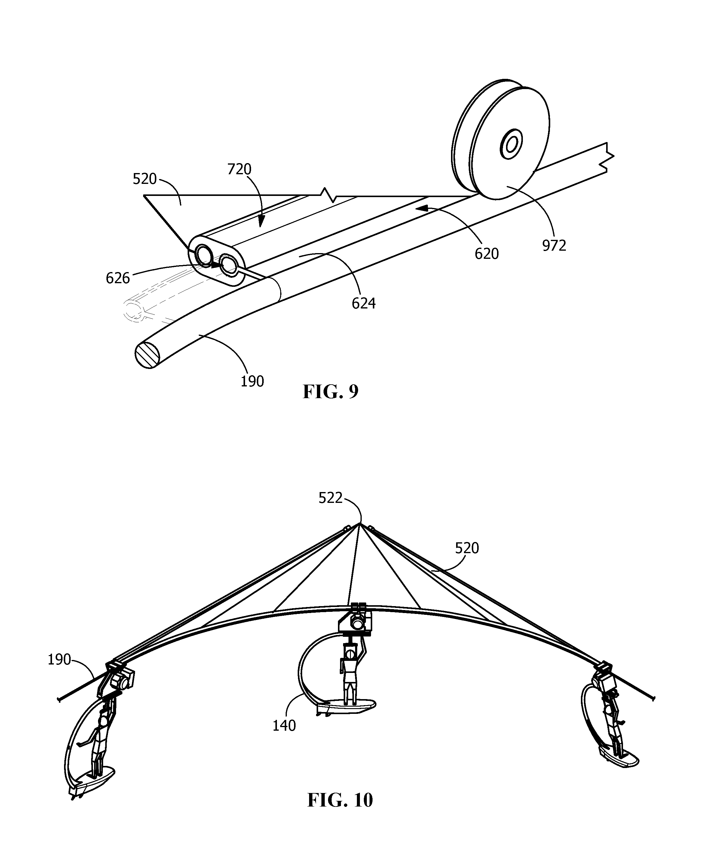
[0051] The intermediate tie-in element 180 is configured to stably support the flexible cable 190 at a location at which the flexible cable 190 can form the first curve run 134 of the travel path assembly 130 and, further, to promote the smooth and reliable travel of the first carriage 140 along the first curve run 134 of the travel path assembly 130. In fulfillment of these objectives, one configuration of the intermediate tie-in element 180 includes a textile sheet 520. Reference is now had to FIG. 7, which is an enlarged top perspective view of a portion of the textile sheet 520 and the travel path assembly 130 adjacent the entry location 136 of the first curve run 134 of the travel path assembly 130, and to FIG. 3, in connection with a description of further details of the cooperative operation of the textile sheet 520 and the flexible cable 190. The textile sheet 520 is formed of a synthetic or non-synthetic material having a relatively significantly smaller thickness than its width and length. An edge of the textile sheet 520 is secured to a batten 612 via a suitable connection, such as, for example, via an overwrap of the selvedge of the textile sheet 520 around the batten 612 secured via stitching, fusing, or riveting.
[0052] Reference is now had to FIG. 8, which is an enlarged sectional top perspective view of a portion of the textile sheet 520, FIG. 9, which is an enlarged sectional top perspective view of a portion of the textile sheet 520 and the travel path assembly 130 adjacent the entry location 136 of the first curve run 134 of the travel path assembly 130, and FIG. 10, which is a schematic top perspective view of the textile sheet 520 and the travel path assembly 130. A remote portion 522 of the textile sheet 520 is secured to the post 264 and an exemplary arrangement for effecting this securement is shown in the form of a pivot ring assembly 550 having an annular base plate 552 fixedly secured to the upper end portion of the post 264 and a rotating annular disc 554 co-extensive with the annular base plate 552 and rotatingly mounted thereon via a ball bearing assembly (not shown) such that the rotating annular disc 554 can rotate relative to the annular base plate 552. The textile sheet 520 is secured to the rotating annular disc 554, whereupon the rotation operation of the rotating annular disc 554 permits the textile sheet 520 to pivot relative to the post 264 through a predetermined range of pivoting motion.
[0053] The flexible cable 190 in the region of the first curve run 134 of the travel path assembly 130 is connected to a stand-off element 620 that is configured with an elongate web 624 having a distal longitudinal rounded edge 626 that has a radius on the order of between two (2) to ten (10) times the thickness of the web 624 and, preferably, at least five (5) times the thickness of the web 624. A proximal longitudinal edge of the web 624 is fixedly secured to the periphery of the flexible cable 190 via a suitable attachment means, such as, for example, welding, brazing, adhesive, or other attachment means. The web 624 extends radially from the flexible cable 190 and the distal longitudinal rounded edge 626 of the stand-off element 620 extends radially outwardly of the web 624.
[0054] One aspect of the path following arrangement 110 that advantageously promotes smooth reliable travel of the first carriage 140 along the first curve run 134 of the travel path assembly 130 is the provision of an arrangement that accommodates relative movement between the textile sheet 520 and the flexible cable 190 in the region of the first curve run 134 of the travel path assembly 130. One exemplary arrangement for accommodating this relative movement between the textile sheet 520 and the flexible cable 190 is illustrated in FIG. 7 and FIG. 3 and includes a buffer element 720 that is configured as an arcuate elongate member having a curvature selected in correspondence with the curvature of the first curve run 134 of the travel path assembly 130 (namely, the arc REF-ARC). As seen in particular in FIG. 7, the buffer element 720 has an inboard surface extending longitudinally and the inboard surface has a centrally located longitudinal opening 722 that forms the entry of an inboard keyhole slot 724. The inboard keyhole slot 724 includes a longitudinally extending cylindrically shaped open chamber 726 communicated with the centrally located longitudinal opening 722 formed on the inboard surface of the buffer element 720. The buffer element 720 includes an outboard surface extending longitudinally and the outboard surface has a centrally located longitudinal opening 730 that forms the entry of an outboard keyhole slot 732. The outboard keyhole slot 732 includes a longitudinally extending cylindrically shaped open chamber 734 communicated with the centrally located longitudinal opening 730 formed on the outboard surface of the buffer element 720.
[0055] The buffer element 720 operates as a liaison structure between the textile sheet 520 and the flexible cable 190 that beneficially permits each of these two components to react to, and handle, forces applied thereto that arise from the movement of carriages along the travel path assembly 130 while the carriages transport loads, such as persons or other cargo. The centrally located longitudinal opening 730 formed in the outboard surface of the buffer element 720 and the longitudinally extending cylindrically shaped open chamber 734 of the outboard keyhole slot 732 are dimensioned in correspondence with the batten 612 to which one edge of the textile sheet 520 is secured such that the batten 612 is movably accommodated within the open chamber 734 of the outboard keyhole slot 732 while the textile sheet 520 extends from the batten 612 through the centrally located longitudinal opening 730 formed in the outboard surface of the buffer element 720. The batten 612 can shift longitudinally along the open chamber 734 of the outboard keyhole slot 732. However, the batten 612 has an overall greater thickness than the height of the centrally located longitudinal opening 730 formed in the outboard surface of the buffer element 720 and the batten 612 is accordingly prevented from moving laterally outwardly of the outboard keyhole slot 724 (the lateral axis extends horizontally perpendicular to the longitudinal extent of the buffer element 720).
[0056] The centrally located longitudinal opening 722 formed in the inboard surface of the buffer element 720 and the longitudinally extending cylindrically shaped open chamber 726 of the inboard keyhole slot 724 are dimensioned in correspondence with the distal longitudinal rounded edge 626 of the web 624 of the stand-off element 620 connected to the flexible cable 190 such that the distal longitudinal rounded edge 626 of the web 624 of the stand-off element 620 is movably accommodated within the open chamber 726 of the inboard keyhole slot 724 while the web 624 of the stand-off element 620 extends from the distal longitudinal rounded edge 626 of the web 624 of the stand-off element 620 through the centrally located longitudinal opening 722 formed in the inboard surface of the buffer element 720. The distal longitudinal rounded edge 626 of the web 624 of the stand-off element 620 can shift longitudinally along the open chamber 726 of the inboard keyhole slot 724. However, the distal longitudinal rounded edge 626 of the web 624 of the stand-off element 620 has an overall greater thickness than the height of the centrally located longitudinal opening 722 formed in the inboard surface of the buffer element 720 and the distal longitudinal rounded edge 626 of the web 624 of the stand-off element 620 is accordingly prevented from moving laterally outwardly of the inboard keyhole slot 724.
[0057] It can thus be understood that the buffer element 720 is accordingly supported in a suspended disposition via the textile sheet 520 and the flexible cable 190. The buffer element 720 interconnects the textile sheet 520 and the flexible cable 190 so that the flexible cable 190 is maintained in a suspended disposition in the region of the first curve run 134 of the travel path assembly 130 via the engagement of the flexible cable 190 at the respective upstream post 262, the textile sheet 520, and the respective downstream post 268. Moreover, the arrangement including the buffer element 720 operatively maintains the flexible cable 190 in sufficient alignment with the arc REF-ARC so as to optimally minimize deleterious deviations from the arc REF-ARC that may detract from the smooth advancing movement of the first carriage 140 along the first curve run 134 of the travel path assembly 130.
[0058] It is believed that the travel of the first carriage 140 along the first curve run 134 of the travel path assembly 130 will be optimized to the degree that the first carriage most closely follows a path of travel along the arc REF-ARC. While there are circumstances in which certain deviations of the path of travel of the first carriage 140 from the arc REF-ARC will not substantially negatively impact the smooth reliable travel of the first carriage along the first curve run 134 of the travel path assembly 130, it is believed that deviations of the path of travel in this manner will, as a general principle, degrade the desired velocity of the first carriage 140, contribute to inducing chattering, rocking, or other undesired instability movements of the first carriage, and/or degrade the feeling of comfort of a passenger transported by the first carriage.
[0059] It can thus be understood that the one embodiment of the path following arrangement of the present invention in the form of the path following arrangement 110 provides an arrangement wherein a carriage (i.e., the first carriage 140) is guided by a single dedicated structure (i.e., the flexible cable 190) during the entire circuit of the carriage completely around a closed loop course.
[0060] In some circumstances, the ability of the arrangement including the buffer element 720 to maintain the flexible cable 190 in sufficient alignment with the arc REF-ARC is enhanced by the feature that the flexible cable 190 can shift relative to the buffer element 720 along the direction of curvature of the flexible cable 190--namely, this capability is the movement of the intermediate tie-in element 180 and the travel path assembly 130 that have been described with respect to FIG. 5 and FIG. 6. The buffer element 720 can be configured to promote such movement via, for example, configuring the inboard keyhole slot 724 and the outboard keyhole slot 732 of the buffer element 720 with relatively low-friction surfaces such as can be provided, for example, if the buffer element 720 is molded of ABS plastic or a suitable polymeric material. Alternatively, the inboard keyhole slot 724 and the outboard keyhole slot 732 of the buffer element 720 can each be configured with a suitable roller wheel arrangement, such as is exemplarily shown in FIG. 11. As seen in FIG. 11, which is an enlarged schematic view of an alternative arrangement of a portion of the buffer element 720, the buffer element 720 can, in lieu of being provided with relatively low friction surface, instead be provided with a plurality of groups of four (4) individual roller wheel assemblies 820 (only one group is illustrated) which are mounted to the open chamber 726 of the inboard keyhole slot 724 at regular intervals longitudinally along the inboard keyhole slot 724. The roller wheel of each roller wheel assembly 820 extends inwardly into the open chamber 726 of the inboard keyhole slot 724 and is mounted on an axle for free rotation as the roller wheel is engaged by the distal longitudinal rounded edge 626 of the web 624 of the stand-off element 620 attached to the flexible cable 190 during longitudinal shifting of the flexible cable 190.
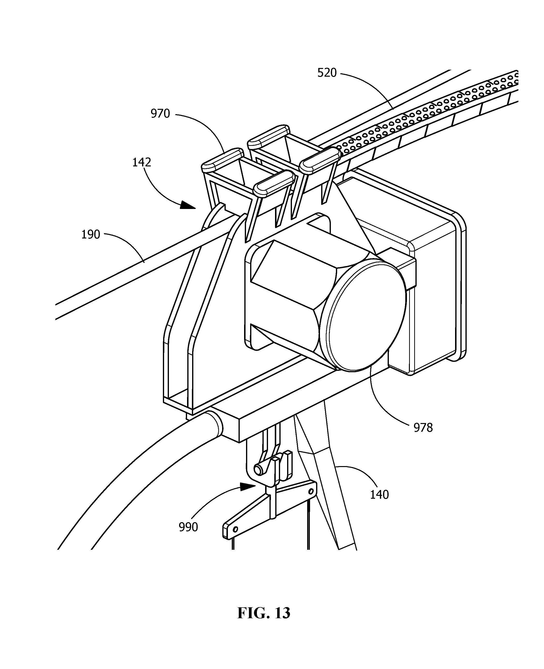
[0061] As seen in FIG. 12, which is an enlarged schematic side view of a portion of the first curve run 134 of the travel path assembly 130 of the one embodiment of the path following arrangement of the present invention showing the first carriage 140, and FIG. 13, which is an enlarged top perspective view of a portion of the first carriage 140 and a portion of the first curve run 134 of the travel path assembly 130 of the one embodiment of the path following arrangement of the present invention, the first carriage 140 comprises a grooved wheel assembly 970 having a pair of top traveler grooved wheels 972 each operable to rollingly travel along an upper hemisphere portion of the flexible cable 190 and a lower traveler grooved wheel 974 operable to rollingly travel along a lower hemisphere portion of the flexible cable 190. At least one of the top traveler grooved wheels 972 and the lower traveler grooved wheels 974 is operatively connected (via, for example, a gear transmission) to an independently powered motor assembly 978. The motor assembly 978 may be configured, for example, as an electric motor having onboard controls (for operational control by a passenger supported on the first carriage 140 and redundantly supported via a harness assembly 990) and/or remotely operable controls (for operational control of the first carriage 140 from a remote or central location).
[0062] The optional deployment of the pivot ring assembly 550 may also enhance the ability of the arrangement including the buffer element 720 to maintain the flexible cable 190 in sufficient alignment with the arc REF-ARC. The pivot ring assembly 550 permits limited rotation or pivoting of the textile sheet 190 relative to the post 264 and this movement may enhance the ability of the flexible cable 190 to shift in a manner that reduces or prevents deviation of the flexible cable from an alignment with the arc REF-ARC.
[0063] In some circumstances, the ability of the arrangement including the buffer element 720 to maintain the flexible cable 190 in sufficient alignment with the arc REF-ARC is enhanced by the feature that the flexible cable 190 can shift relative to the posts 264 and 266 to which the textile sheet 520 is secured--namely, this capability is the capability that the first curve run 134 of the travel path assembly 130 can be restorably displaced, in the displacement direction DIS-DR perpendicular to the tangent TL-T of the arc REF-ARC, from its home disposition to its temporary displacement disposition in response to the application of a force on the travel path assembly 130. This movement can be accommodated, for example, via configuring the textile sheet 520 of a fabric having a resilient expansion property that permits the textile sheet 520 to resiliently expand in response to an expansion force applied thereto and then return to its original shape. Alternatively, the textile sheet 520 sheet can be connected with a structure having spring properties that permit the structure to be distorted from an original shape and that resiliently returns to its original shape.
[0064] With reference now to FIG. 14, which is a front enlarged schematic view of a variation of the intermediate tie-in element of the one embodiment of the path following arrangement of the present invention, an intermediate tie-in element 980 includes the textile sheet 520 and, in lieu of the buffer element 720 shown and described in connection with the one embodiment of the path following arrangement of the present invention, the intermediate tie-in element 980 includes a bridge-over retention assembly 982. The bridge-over retention assembly 982 includes a plurality of bridge flanges 984 (only one of which is shown) each having a pair of clamping jaws 986 that compressively engage an edge portion of the textile sheet 520 and the bridge flanges 984 are uniformly longitudinally distributed along the first curve run 134 of the travel path assembly 130, whereupon the pairs of clamping jaws 986 engage the textile sheet 520 at multiple locations. The clamping jaws 986 of each bridge flange 984 are mounted to one end of a rod segment having a plurality of bent sections that are collectively configured to extend over the flexible cable 190. Each bridge flange 984 has a remote end structure in the form of a truncated version of the buffer element 720--namely, each remote end structure is configured to include the inboard keyhole slot 724 configuration including the centrally located longitudinal opening 722 formed in the inboard surface of the buffer element 720 and the longitudinally extending cylindrically shaped open chamber 726 and these are dimensioned in correspondence with the distal longitudinal rounded edge 626 of the web 624 of the stand-off element 620 connected to the flexible cable 190 such that the distal longitudinal rounded edge 626 of the web 624 of the stand-off element 620 is movably accommodated within the open chamber 726 of the inboard keyhole slot 724 while the web 624 of the stand-off element 620 extends from the distal longitudinal rounded edge 626 of the web 624 of the stand-off element 620 through the centrally located longitudinal opening 722 formed in the inboard surface of the buffer element 720. The bridge-over retention assembly 982 thus engages the flexible cable 190 to secure the flexible cable relative to the textile sheet 520.
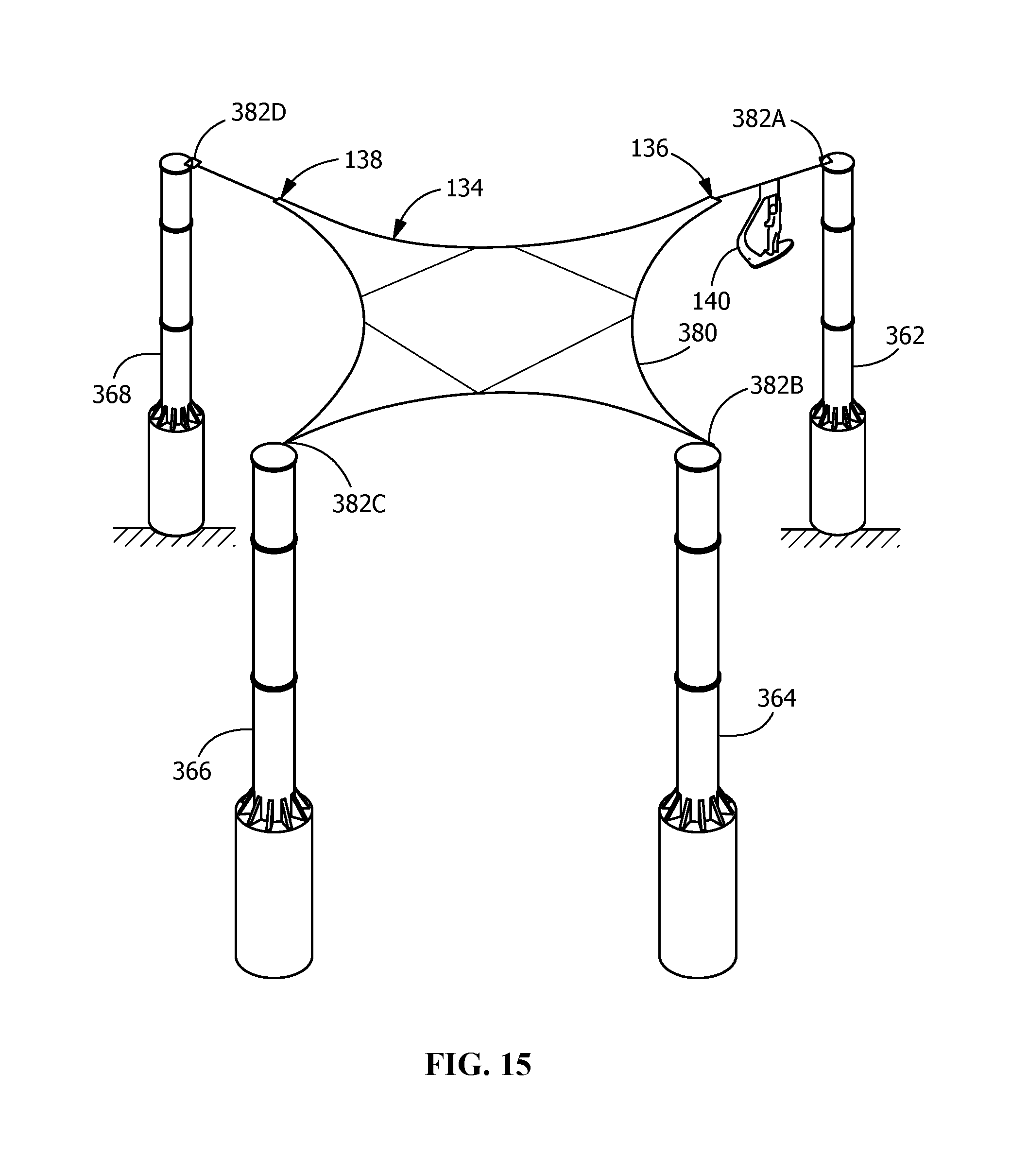
[0065] With reference now to FIG. 15, which is a top schematic perspective view of an additional embodiment of the path following arrangement of the present invention, the travel path assembly 130 is comprised of a single length of a flexible cable that forms the entirety of the course that is traveled by the first carriage 140 and the course has a semi-annular configuration that is not a complete loop. Specifically, the course has the geometry of a single curve of uniform radius. One axial end of the flexible cable of the travel path assembly 130 is secured to a post 362, which forms the upstream anchor location that is upstream of the entry 136 of the first curve run 134 of the travel assembly 130 and the opposite axial end of the flexible cable of the travel path assembly 130 is secured to a post 368 that forms the downstream anchor location that is downstream of the exit of the first curve run 134 of the travel assembly 130. An intermediate tie-in element 380 includes a textile sheet 520 having a total of four (4) connection vertices 382A-D each secured to the upper end of a respective one of the posts 362, 364, 366, and 368 in a manner such that the textile sheet 520 is held in a relatively taut, planar horizontal orientation.
[0066] The intermediate tie-in element 380 includes a bridge-over retention assembly, such as has been shown and described with respect to FIG. 14, and this bridge-over retention assembly is secured to the textile sheet 520. The bridge-over retention assembly engages the flexible cable 190 to secure the flexible cable relative to the textile sheet 520.
[0067] The entry 136 and the exit 138 of the first curve run 134 of the travel path assembly 130 delimit an arc of a reference circle and the reference circle delimits the single curve of uniform radius that comprises the course of the travel path assembly 130 of the additional one embodiment of the path following arrangement of the present invention. The entry 136 of the first curve run 134 of the travel path assembly 130 is downstream of the connection vertex 382A secured to the post 362 and the exit 138 of the first curve run 134 of the travel path assembly 130 is upstream of the connection vertex 382D secured to the post 368.
[0068] FIG. 16 is a top enlarged perspective view of a portion of the one embodiment of the path following arrangement of the present invention shown in FIG. 1. FIG. 16 shows details of the upper portion of the first carriage 140 including a framework on which roller wheels are rotatably mounted and which rollingly travel along the flexible cable 190.
[0069] FIG. 17 is a top perspective view of a portion of a further variation of the one embodiment of the path following arrangement of the present invention shown in FIG. 1. FIG. 17 shows an arrangement for securing the flexible cable 190 to a post, such as the post 264, wherein, in lieu of the textile sheet 520, a plurality of post cables 530 are provided, each of which has one axial end secured to a manifold panel 532 that itself is secured to the post 264. The opposite axial end of each post cable 530 is secured to the batten 612. A pair of guy wires 536 extend to and between the post 264 and the reference surface 150 and contribute to enhancing the stability of the post 264.
[0070] According to another aspect of the present invention, a method for operating a path following arrangement having a catenary structure is provided. In connection with an exemplary execution of the method of the present invention, the method includes a step of loading a first carriage with a load and a step of disposing the first carriage for travel on a travel path assembly of a catenary structure. The catenary structure is configured with a travel path assembly delimiting a course along which the first carriage can travel while supported at a spacing from a reference surface and the travel path assembly including a first change of direction run having an entry and an exit. The first carriage has an engagement element operable to engage the travel path assembly in a manner that permits the first carriage to move relatively along the travel path assembly while being guided thereby and the first carriage being movable relatively along the travel path assembly in a travel direction such that the first carriage initially enters the first change of direction run via the entry thereof and thereafter exits the first change of direction run via the exit thereof during each passage of the first carriage along the first change of direction run.
[0071] Additionally, the catenary structure includes an upstream anchor location, a downstream anchor location, and an intermediate tie-in element, the upstream anchor location engaging a portion of the travel path assembly and the upstream anchor location and the intermediate tie-in element cooperating with one another to maintain the travel path assembly in a supported disposition such that the first carriage can travel along the course upstream of the first change of direction run, relative to the travel direction, while supported at a spacing from the reference surface. Moreover, the downstream anchor location engages a portion of the travel path assembly and the intermediate tie-in element and the downstream anchor location cooperate with one another to maintain the travel path assembly in a supported disposition such that the first carriage can continue to travel along the course while supported at a spacing from the reference surface after the first carriage has exited the first change of direction run.
[0072] The entry and the exit of the first change of direction run delimit an arc of a reference circle, the arc having a tangent. The travel path assembly and the intermediate tie-in element are operatively interconnected such that the first change of direction run of the travel path assembly can be restorably displaced, in a displacement direction perpendicular to the tangent of the arc delimited by first change of direction run of the travel path assembly, from a home disposition to a temporary displacement disposition in response to the application of a force on the travel path assembly during the travel of the first carriage along the first change of direction run and can be restored to its home disposition from its temporary displacement disposition. Additionally, the intermediate tie-in element has an upstream end and a downstream end and the upstream end of the intermediate tie-in element and the entry location of the first change of direction run of the travel path assembly are at a predetermined spacing from one another in a base disposition. The intermediate tie-in element and the travel path assembly are movable relative to one another such that the travel path assembly and the intermediate tie-in element can be restorably displaced from the base disposition in which the upstream end of the intermediate tie-in element and the entry location of the first change of direction run of the travel path assembly are at a predetermined spacing from one another to an offset disposition in which the upstream end of the intermediate tie-in element and the entry location of the first change of direction run of the travel path assembly have moved relative to one another in response to the application of a force on the travel path assembly, wherein the upstream end of the intermediate tie-in element and the entry location of the first change of direction run of the travel path assembly are at an offset spacing from one another that is different than the predetermined spacing from one another in the base disposition. The intermediate tie-in element and the travel path assembly are operable to be returned to their base disposition from their offset disposition.
[0073] While the disclosure has been described with reference to an embodiment, it will be understood by those skilled in the art that various changes may be made and equivalents may be substituted for elements thereof without departing from the scope of the disclosure. In addition, many modifications may be made to adapt a particular situation or material to the teachings of the disclosure without departing from the essential scope thereof. Therefore, it is intended that the disclosure not be limited to the particular embodiment disclosed as the best mode contemplated for carrying out this disclosure, but that the disclosure will include all embodiments falling within the scope of the appended claims.
* * * * *
D00000
D00001
D00002
D00003
D00004
D00005
D00006
D00007
D00008
D00009
D00010
D00011
D00012

D00013
XML
uspto.report is an independent third-party trademark research tool that is not affiliated, endorsed, or sponsored by the United States Patent and Trademark Office (USPTO) or any other governmental organization. The information provided by uspto.report is based on publicly available data at the time of writing and is intended for informational purposes only.
While we strive to provide accurate and up-to-date information, we do not guarantee the accuracy, completeness, reliability, or suitability of the information displayed on this site. The use of this site is at your own risk. Any reliance you place on such information is therefore strictly at your own risk.
All official trademark data, including owner information, should be verified by visiting the official USPTO website at www.uspto.gov. This site is not intended to replace professional legal advice and should not be used as a substitute for consulting with a legal professional who is knowledgeable about trademark law.