Battery Tray Floor Assembly For Electric Vehicles
Matecki; Joseph Robert ; et al.
U.S. patent application number 16/152147 was filed with the patent office on 2019-04-04 for battery tray floor assembly for electric vehicles. The applicant listed for this patent is Shape Corp.. Invention is credited to Joseph Robert Matecki, Mark Charles Stephens, Helen Weykamp.
| Application Number | 20190100090 16/152147 |
| Document ID | / |
| Family ID | 65897571 |
| Filed Date | 2019-04-04 |


View All Diagrams
| United States Patent Application | 20190100090 |
| Kind Code | A1 |
| Matecki; Joseph Robert ; et al. | April 4, 2019 |
BATTERY TRAY FLOOR ASSEMBLY FOR ELECTRIC VEHICLES
Abstract
A vehicle battery tray has a floor assembly with elongated tray sections that attach together at edge portions of adjacent tray sections of the elongated tray sections to form a floor structure that supports vehicle batteries contained in the vehicle battery tray. The elongated tray sections may have substantially consistent cross-sectional shapes that extends along a length of the tray sections. A thickness of the tray sections at a central area of the floor structure may be greater than a thickness of another one of the elongated tray sections at an outboard area of the floor structure, such as to withstand an equal or greater transverse bending moment than the outboard area of the floor structure.
| Inventors: | Matecki; Joseph Robert; (Allendale, MI) ; Stephens; Mark Charles; (Grand Rapids, MI) ; Weykamp; Helen; (Grand Haven, MI) | ||||||||||
| Applicant: |
|
||||||||||
|---|---|---|---|---|---|---|---|---|---|---|---|
| Family ID: | 65897571 | ||||||||||
| Appl. No.: | 16/152147 | ||||||||||
| Filed: | October 4, 2018 |
Related U.S. Patent Documents
| Application Number | Filing Date | Patent Number | ||
|---|---|---|---|---|
| 62568051 | Oct 4, 2017 | |||
| Current U.S. Class: | 1/1 |
| Current CPC Class: | B60Y 2410/124 20130101; H01M 2/1072 20130101; B60Y 2410/125 20130101; B60L 50/66 20190201; B60Y 2306/01 20130101; H01M 2/1077 20130101; B60K 1/04 20130101; H01M 2/1083 20130101; H01M 2220/20 20130101; B60K 2001/0438 20130101 |
| International Class: | B60K 1/04 20060101 B60K001/04; B60L 11/18 20060101 B60L011/18; H01M 2/10 20060101 H01M002/10 |
Claims
1. A vehicle battery tray comprising: a floor assembly having a plurality of elongated tray sections that attach together at lateral edge portions of adjacent tray sections of the plurality of elongated tray sections to form a floor structure that is configured to support vehicle batteries contained in the vehicle battery tray; wherein the plurality of elongated tray sections each comprise a substantially consistent cross-sectional shape extending longitudinally along a length of the elongated tray section; and wherein a thickness of one of the plurality of elongated tray sections at a central area of the floor structure is greater than a thickness of another one of the plurality of elongated tray sections at an outboard area of the floor structure.
2. The vehicle battery tray of claim 1, wherein at least one of the plurality of elongated tray sections comprises an aluminum alloy, and wherein the central area of the floor structure is configured to withstand an equal or greater transverse bending moment than the outboard area of the floor structure.
3. The vehicle battery tray of claim 1, wherein each of the plurality of elongated tray sections comprises an upper panel portion that at least partially forms an upper surface of the floor structure formed by the plurality of tray sections.
4. The vehicle battery tray of claim 3, wherein each of the plurality of elongated tray sections comprises a lower panel portion that is separated from the upper panel portion to provide a hollow area extending longitudinally along the length of the respective tray section.
5. The vehicle battery tray of claim 4, wherein each of the plurality of elongated tray sections comprises intermediate members that integrally interconnect between the upper and lower panel portions to divide the hollow area into multiple elongated hollow channels disposed between the upper and lower panel portions.
6. The vehicle battery tray of claim 1, wherein an outer tray section of the plurality of elongated tray sections comprises a panel portion that partially forms the floor structure, and wherein the outer tray section comprises a wall portion integrally protruding upward from the panel portion of the outer tray section to at least partially form a peripheral wall structure of the vehicle battery tray.
7. The vehicle battery tray of claim 6, wherein the wall portion of the outer tray section comprises an hollow area extending longitudinally along the length of the outer tray section.
8. The vehicle battery tray of claim 1, wherein at least one of the lateral edge portions of the plurality of elongated tray sections includes a substantially horizontal surface that attaches at a corresponding substantially horizontal surface of the adjacent tray section.
9. The vehicle battery tray of claim 1, wherein, when in an initially formed state, at least two adjacent tray sections of the plurality of tray sections are integrally interconnected, and wherein the at least two adjacent tray sections are displaced from the initially formed state to an assembly state that horizontally aligns the at least two adjacent tray sections to at least partially form the floor structure.
10. The vehicle battery tray of claim 1, wherein the plurality of elongated tray sections comprises an inner tray section disposed at the central area of the floor structure and outer tray sections disposed at the outboard areas of the floor structure.
11. The vehicle battery tray of claim 10, wherein the outer tray sections each comprise a wall portion, and wherein the vehicle battery tray comprises front and rear tray enclosure members that extend laterally across the plurality of elongated tray section and attach at the wall portions of the outer tray sections to together form a peripheral wall structure that surrounds a battery containment area of the vehicle battery tray.
12. A tray floor assembly for a vehicle battery tray, said tray floor assembly comprising: a plurality of elongated tray sections that attach together to form a substantially planar floor structure that is configured to support vehicle batteries; wherein the plurality of elongated tray sections each extend longitudinally and parallel relative to each other and each comprise a transverse cross-sectional profile that is substantially consistent longitudinally along its length; and wherein the cross-sectional profile of at least one of the plurality of elongated tray sections includes a thickness between an upper surface and a lower surface of the floor structure that increases laterally across a width of the cross-sectional profile.
13. The tray floor assembly of claim 12, wherein the thickness at a central area of the floor structure is greater than the thickness at opposing outboard areas of the floor structure.
14. The tray floor assembly of claim 12, wherein at least one of the plurality of elongated tray sections comprises an aluminum extrusion.
15. The tray floor assembly of claim 12, wherein at least one of the plurality of elongated tray sections comprises (i) an upper panel portion that at least partially forms the upper surface of the floor structure, (ii) a lower panel portion that is separated from the upper panel portion to provide a hollow area extending longitudinally along the length of the respective tray section, and (iii) intermediate stiffening members that integrally interconnect between the upper and lower panel portions to laterally divide the hollow area.
16. The tray floor assembly of claim 12, wherein the plurality of elongated tray sections comprises outer tray sections on opposing lateral sides of the floor structure that each have a wall portion that partially forms a peripheral wall structure of the vehicle battery tray.
17. The tray floor assembly of claim 12, wherein adjacent tray sections of the plurality of tray sections attach together to form the floor structure, and wherein the upper surfaces of the adjacent tray sections are fixed in substantially planar alignment.
18. The tray floor assembly of claim 17, wherein, when in an initially formed state, the adjacent tray sections of the plurality of tray sections are integrally interconnected, and wherein the adjacent tray sections are displaced from the initially formed state to an assembly state for disposing the adjacent tray sections with the upper surfaces in substantially planar alignment with each other.
19. A battery tray for an electric vehicle, said battery tray comprising: a plurality of elongated tray sections that extend longitudinally and together to form a floor structure of the battery tray that has a substantially planar upper surface that is configured to support batteries that supply operational power to the electric vehicle; wherein the plurality of elongated tray sections comprises outer tray sections on opposing lateral sides of the floor structure that each have a wall portion that partially forms a peripheral wall structure that surrounds a battery containment area of the vehicle battery tray; and wherein the plurality of elongated tray sections comprises an inner tray section disposed between the outer tray sections and having a thickness defined between the upper surface and a lower surface of the floor structure that is greater than a thickness of the floor structure at the outer tray sections.
20. The battery tray of claim 19, wherein the plurality of tray sections are each formed from an extrusion process or a pultrusion process to provide a transverse cross-sectional profile that is substantially consistent longitudinally along its length, and wherein the plurality of tray sections each include an attachment feature that attaches at a corresponding attachment feature of an adjacent tray section of the plurality of tray sections.
Description
CROSS-REFERENCE TO RELATED APPLICATION
[0001] This application claims benefit and priority under 35 U.S.C. .sctn. 119(e) of U.S. provisional application Ser. No. 62/568,051, filed Oct. 4, 2017, which is hereby incorporated herein by reference in its entirety.
TECHNICAL FIELD
[0002] The present invention generally relates to vehicle battery support structures, and more particularly to tray and floor structures for holding and supporting protected batteries, such as battery packs or modules or the like for electric and hybrid-electric vehicles.
BACKGROUND
[0003] Electric and hybrid-electric vehicles are typically designed to locate and package battery modules on the vehicle in a manner that protects the batteries from damage when driving in various climates and environments, and also that protects the batteries from different types of impacts. It is also fairly common for vehicle frames to locate batteries in a portion of the frame or sub-structure of the vehicle, such as between the axles and near the floor of the vehicle, which can distribute the weight of the batteries across the vehicle frame and establish a low center of gravity for the vehicle.
SUMMARY
[0004] A battery tray for an electric vehicle has a floor that spans below the batteries held in a battery containment area. The floor is provided as a tray floor assembly that may be engineered or configured to reduce the weight of the overall battery tray, while also providing the desired structural support to the contained batteries and the desired protective attributes, such as impact resistance to the lower surface the battery tray. The tray floor assembly has elongated tray sections that may be extruded, such as with aluminum, or pultruded, such as with a resin and composite substrate, to form a cross-sectional profile that is substantially consistent longitudinally along the length of each tray section. The elongated tray sections may be attached or otherwise arranged together in a manner so as to form a floor structure with a varied cross-sectional profile across a width of the tray, such as to have structural mass at the desired locations of the floor structure to support loads of the vehicle batteries arranged over the floor of the battery tray. Also, exterior or outboard tray sections of the floor assembly may include a wall portion that extends longitudinally along the exterior or outboard tray section to provide a section of a peripheral wall structure of the battery tray. The wall structure section or sections provided by the floor assembly may further have wall thicknesses and longitudinal elongated hollow areas that are configured to laterally protect the battery containment area, such as to prevent lateral impact forces from objects hitting the vehicle from substantially penetrating the battery containment area.
[0005] According to one aspect of the present disclosure, a vehicle battery tray has a floor assembly with elongated tray sections that attach together at lateral edge portions of adjacent tray sections of the elongated tray sections to form a floor structure. This floor structure is configured to support vehicle batteries contained in the vehicle battery tray. The elongated tray sections each have a substantially consistent cross-sectional shape that extends longitudinally along a length of the elongated tray sections. A thickness of one of the elongated tray sections at a central area of the floor structure is greater than a thickness of another one of the elongated tray sections at an outboard area of the floor structure. The central area of the floor structure may further be configured to withstand an equal or greater transverse bending moment than the outboard area of the floor structure.
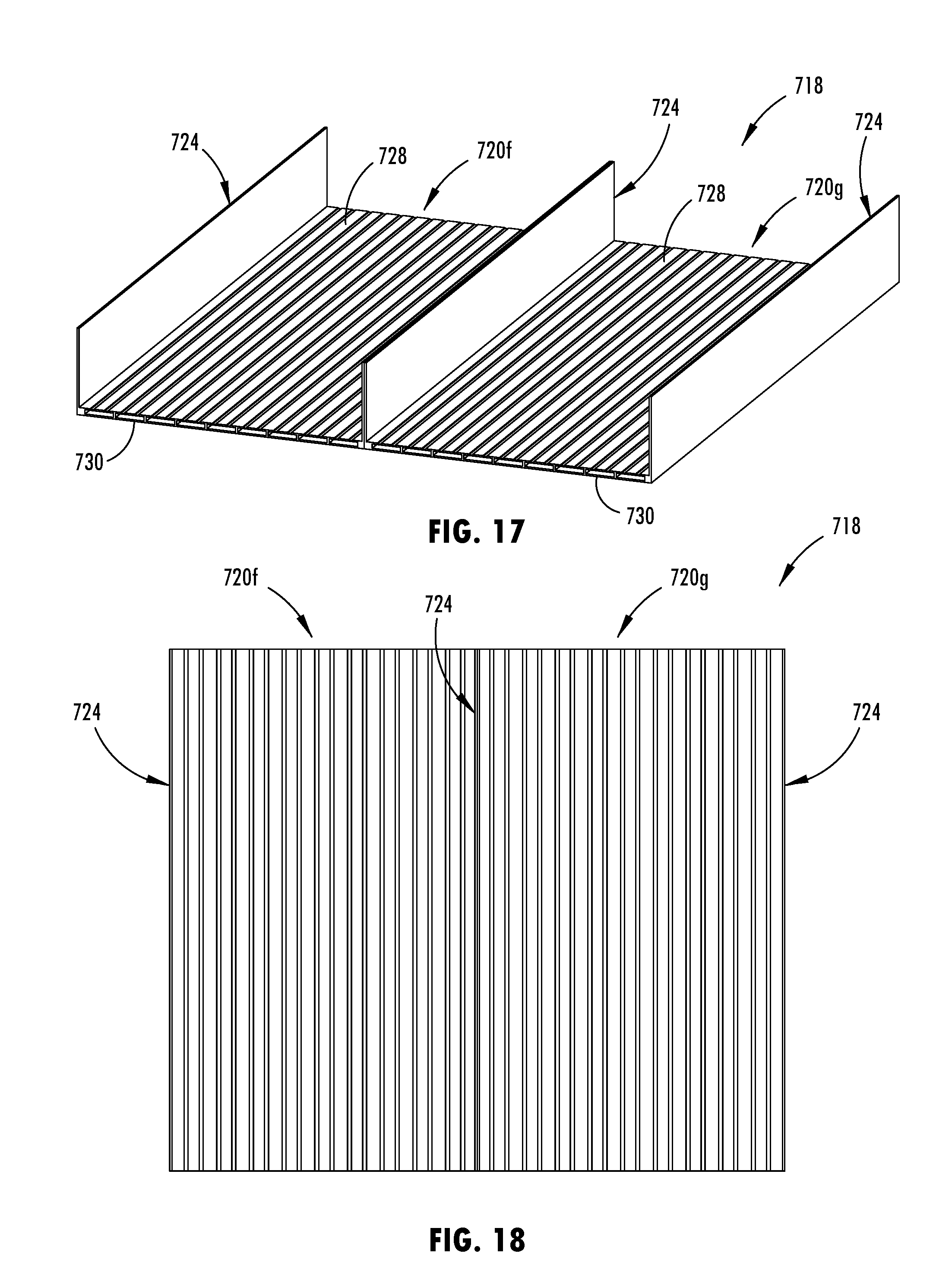
[0006] According to another aspect of the present disclosure, a tray floor assembly for a vehicle battery tray has elongated tray sections that attach together to form a substantially planar floor structure that is configured to support vehicle batteries. The elongated tray sections each extend longitudinally and parallel relative to each other and each have a transverse cross-sectional profile that is substantially consistent longitudinally along its length. The cross-sectional profile of at least one of the elongated tray sections includes a thickness between an upper surface and a lower surface of the floor structure that increases laterally across a width of the cross-sectional profile. At least one of the elongated tray sections may also have an upper panel portion that at least partially forms the upper surface of the floor structure and a lower panel portion that is separated from the upper panel portion to provide a hollow area extending longitudinally along the length of the respective tray section. The upper panel portion may be supported away from the lower panel portion by intermediate stiffening members that integrally interconnect between the upper and lower panel portions, so as to laterally divide the hollow area disposed therebetween.
[0007] According to yet another aspect of the present disclosure, a battery tray for an electric vehicle includes elongated tray sections that extend longitudinally and together to form a floor structure of the battery tray that has a substantially planar upper surface that is configured to support batteries that supply operational power to the electric vehicle. The elongated tray sections include outer tray sections on opposing lateral sides of the floor structure that each have a wall portion that partially forms a peripheral wall structure that surrounds a battery containment area of the vehicle battery tray. The elongated tray sections may also include an inner tray section that is disposed between the outer tray sections and that has a thickness defined between the upper surface and a lower surface of the floor structure that is greater than a thickness of the floor structure at the outer tray sections.
[0008] Furthermore, when in an initially formed state, adjacent tray sections of a battery tray assembly may be integrally interconnected, such that these adjacent tray sections may be displaced from the initially formed state to an assembly state for arranging the adjacent tray sections with the respective upper surfaces in substantially planar alignment with each other to form the floor structure of the battery tray.
[0009] These and other objects, advantages, purposes, and features of the present disclosure will become apparent upon review of the following specification in conjunction with the drawings.
BRIEF DESCRIPTION OF THE DRAWINGS
[0010] FIG. 1 is a side elevational view of a battery support structure secured at a mounting location on a vehicle;
[0011] FIG. 2 is top plan view of the battery support structure shown in FIG. 1, illustrating rocker rails and other portions of the vehicle in dashed lines;
[0012] FIG. 3 is an upper perspective view of a tray floor assembly of the battery support structure shown in FIG. 1;
[0013] FIG. 4 is a top plan view of the tray floor assembly shown in FIG. 3;
[0014] FIG. 5 is an end elevational view of the tray floor assembly shown in FIG. 3;
[0015] FIG. 5A is an enlarged view of an outer section of the tray floor assembly shown in FIG. 5;
[0016] FIG. 5B is an enlarged view of a lap joint of the tray floor assembly shown in FIG. 5A, showing an attachment interface between elongated tray sections;
[0017] FIG. 6 is an exploded upper perspective view of the elongated tray sections of the tray floor assembly shown in FIG. 3;
[0018] FIG. 7 is an upper perspective view of an additional embodiment of a battery tray floor assembly;
[0019] FIG. 8 is a top plan view of the tray floor assembly shown in FIG. 7;
[0020] FIG. 9 is an end elevational view of the tray floor assembly shown in FIG. 7;
[0021] FIG. 9A is an enlarged view of an outer section of the tray floor assembly shown in FIG. 7;
[0022] FIG. 9B is an enlarged view of a lap joint of the tray floor assembly shown in FIG. 9A, showing an attachment interface between elongated tray sections;
[0023] FIG. 10 is an exploded upper perspective view of the elongated tray sections of the tray floor assembly shown in FIG. 7;
[0024] FIG. 11 is a cross-sectional view of an additional embodiment of a battery tray floor assembly, showing two tray sections;
[0025] FIG. 12 is a cross-sectional view of an additional embodiment of a battery tray floor assembly, showing two tray sections;
[0026] FIG. 13A is a cross-sectional view of an additional embodiment of a battery tray floor assembly, showing two tray sections in a formed state;
[0027] FIG. 13B is a cross-sectional view of the battery tray floor assembly of FIG. 13A, showing the two tray sections in a use state;
[0028] FIG. 14A is a cross-sectional view of an additional embodiment of a battery tray floor assembly, showing two tray sections in a formed state;
[0029] FIG. 14B is a cross-sectional view of the battery tray floor assembly of FIG. 14A, showing the two tray sections in a use state;
[0030] FIG. 15A is a cross-sectional view of an additional embodiment of a battery tray floor assembly, showing tray sections in a formed state;
[0031] FIG. 15B is a cross-sectional view of the battery tray floor assembly of FIG. 15A, showing the tray sections in a use state;
[0032] FIG. 16 shows top plan views and corresponding cross-sectional views of a battery tray floor assembly alongside a monolithic floor structure, showing trimmed sections removed;
[0033] FIG. 17 is an upper perspective view of an additional battery tray floor assembly;
[0034] FIG. 18 is a top plan view of the tray floor assembly shown in FIG. 17;
[0035] FIG. 19 is an end elevational view of the tray floor assembly shown in FIG. 17; and
[0036] FIG. 20 is an enlarged perspective view of the tray floor assembly shown in FIG. 17, showing the tray sections exploded away from each other.
DETAILED DESCRIPTION
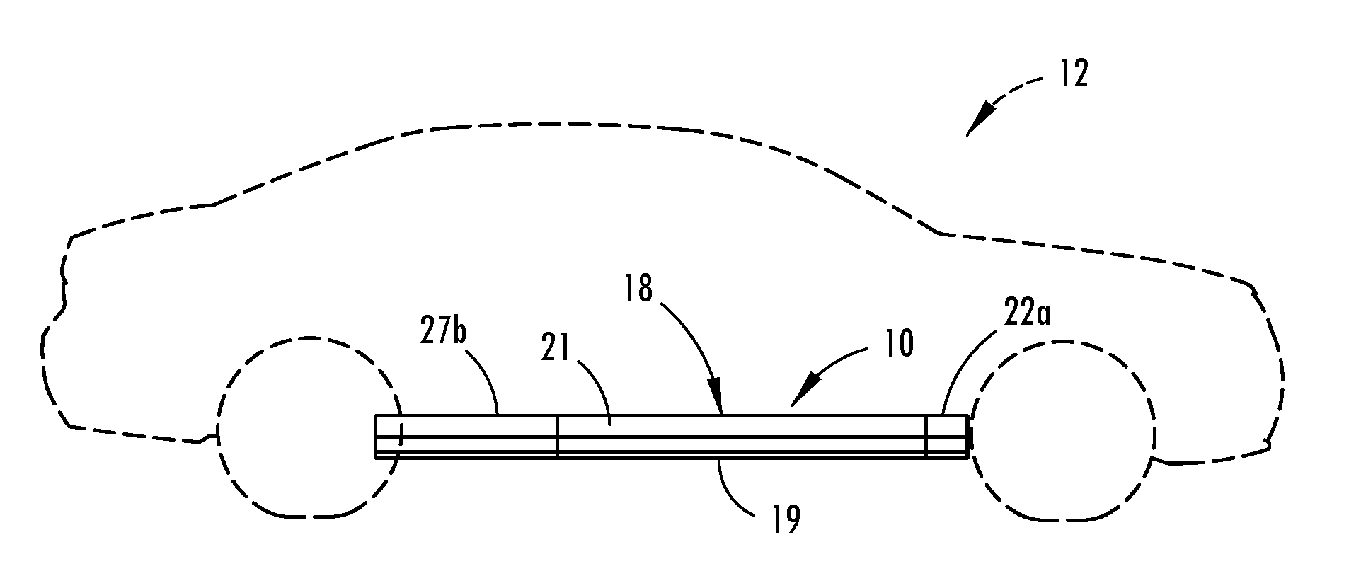
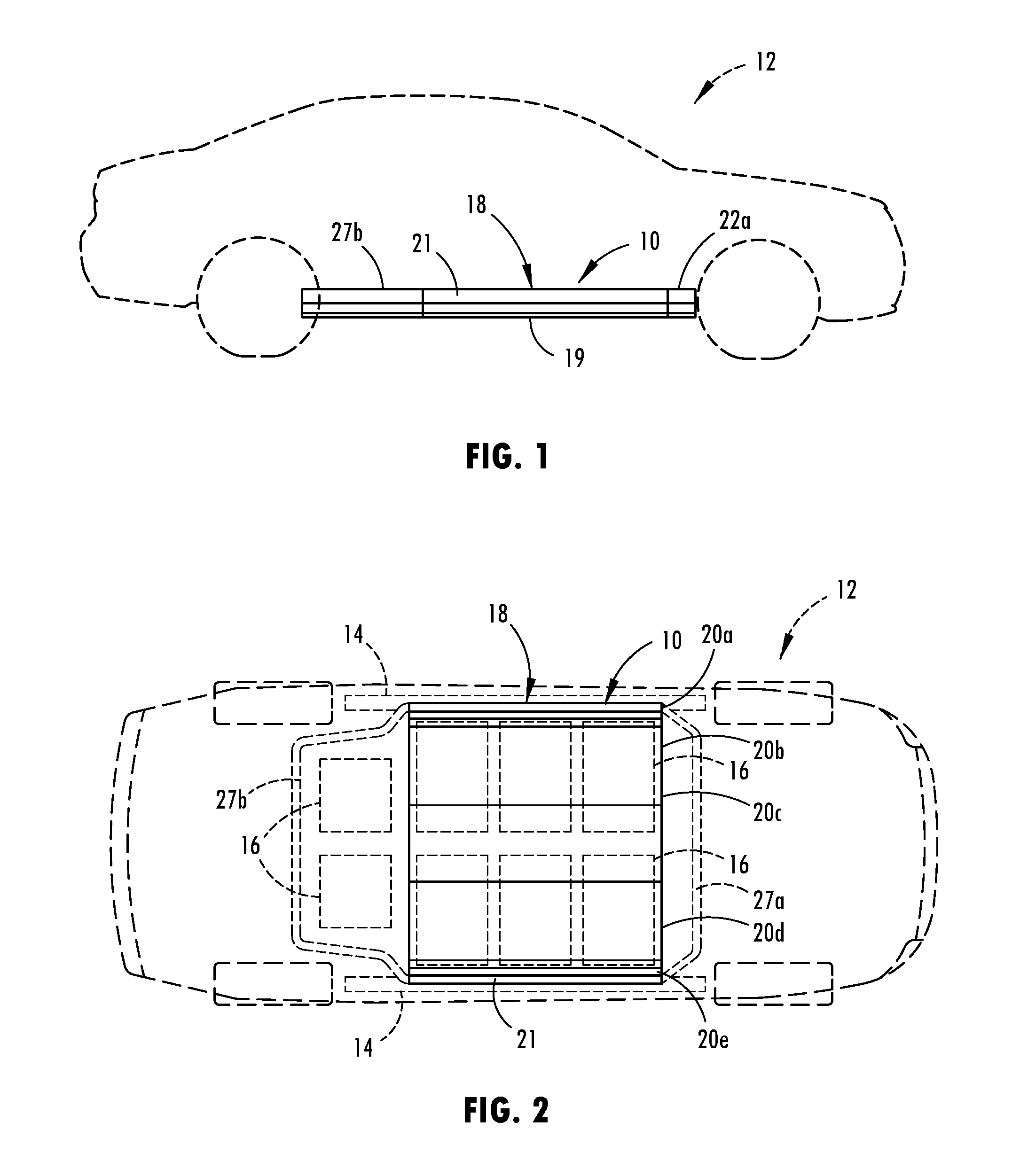
[0037] Referring now to the drawings and the illustrative embodiments depicted therein, a vehicle battery tray or structure 10 is provided for supporting and protecting batteries, such as battery packs or modules or the like, for operating a vehicle 12 (FIG. 1), such as for operating of an electric vehicle or hybrid-electric vehicle. The battery tray 10 may be attached or mounted at or near the lower frame or rocker rails 14 of the vehicle 12 (FIG. 2), so as to locate the contained batteries 16 generally in a central location on the vehicle 12, which is generally away from probable impact locations and also in a location that may evenly distribute the weight of the batteries 16 over the vehicle frame. Such an attachment or mounting location at the bottom area of the vehicle frame may also provide the vehicle with a relatively lower center of gravity. The battery tray 10 spans below the vehicle 12, such as shown in FIG. 1, with a generally thin profile, so as to accommodate various vehicle body types and designs. For further usage considerations, it is contemplated that the battery tray 10 may be easily disengaged or detachable from the rocker rails 14 of the vehicle 12, such as for replacing or performing maintenance on the batteries 16 or related electrical components.
[0038] The battery tray 10 includes a battery tray floor assembly 18 that spans below the batteries 16 contained in the battery tray 10, so as to at least partially form an interior surface of a battery containment area of the battery tray 10. Moreover, such as shown in FIG. 1, a bottom surface 19 of the floor assembly 18 of the battery tray 10 may be exposed to generally provide an undercarriage surface of the vehicle body that faces and is suspended away from the road or ground surface. The tray floor assembly 18 has elongated tray sections that are attached or otherwise arranged together in a manner to form a floor structure 22 of the battery tray 10, such as shown in FIG. 4. The floor structure 22 formed by the tray sections provide the desired structural support to the contained batteries 16 and the desired protective attributes, such as impact resistance to the lower surface 19 the battery tray 10.
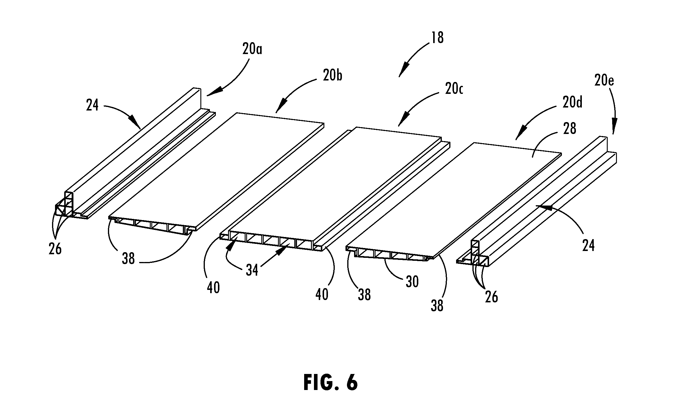
[0039] As shown in FIGS. 2-6, the tray floor assembly 18 of the battery tray 10 provides five separate tray sections 20a, 20b, 20c, 20d, 20e that extend longitudinally in parallel alignment with each other and are attach together at lateral edge portions of adjacent tray sections to form the floor structure 22. These elongated tray sections 20a, 20b, 20c, 20d, 20e are formed to each have a cross-sectional profile taken transverse to the longitudinal length that is substantially consistent longitudinally along the length of each tray section. Such a generally consistent profile along the length of a tray section may be formed by extrusion, such as with an aluminum alloy, or pultrusion, such as with a resin and composite substrate. For example, the tray sections may be extruded with 6xxx or 7xxx series aluminum alloy or pultruded with carbon fiber strands and mats reinforced with a resin system. It is understood that a tray floor assembly may have more or fewer tray sections than shown in FIGS. 3-6, such as shown in the additional illustrated examples herein, and furthermore understood that tray sections may be formed separate from each other or integrally formed together, as described in examples below. In addition to the different exemplary structural configurations shown and described below, it is understood that other conceivable structural designs may be used to provide the varied floor structure 22 for the desired structural performance characteristics.
[0040] The open front and rear ends of the tray floor assembly 18 may be enclosed with structural modules or cross members to further protect the batteries 16 held in the containment area and provide the desired peripheral shape of the battery tray 10. As shown in FIGS. 1 and 2, the vehicle battery tray 10 has front and rear tray enclosure members 27a, 27b that extend laterally across the tray floor assembly 18 and attach at the wall portions of the outer tray sections 20a, 20e to together form a peripheral wall structure 21 that surrounds the battery containment area of the vehicle battery tray 10. The front and rear tray enclosure members 27a, 27b may engage within the hollow openings of the wall portions of the outer tray sections and may attach thereat via welding, adhesive, and/or fasteners, and other conceivable means of attachment. Moreover the front and rear tray enclosure members 27a, 27b may be part of a module that includes a floor section that aligns with the floor assembly 18 and is capable of supporting additional batteries, such as shown in FIG. 2.
[0041] The cross-sectional profile of one or more of the tray sections may be engineered or otherwise configured with the desired structure to support the loads of the vehicle batteries 16 and/or other related contents of the battery tray 10 at the respective tray section, such that the structural shape and design of the floor structure 22 may vary across the tray floor assembly 18. As shown in FIGS. 5-5B, the tray sections 20a, 20b, 20c, 20d, 20e may each have an upper panel portion 28 and a lower panel portion 30 that are separated from each other by intermediate members 32 that interconnect the upper and lower panel portions 28, 30 and consistently extend longitudinally along the length of the respective tray section. Accordingly, hollow areas 34 may be defined between the upper and lower panel portions 28, 30 that also extend longitudinally along the intermediate members 32, so as to laterally separate the hollow areas 34 from each other and vertically separate the upper and lower panel portions 29, 30 from each other.
[0042] The vertical spacing provided by the hollow areas 34 creates a distance to allow upward deformation of the lower panel portion 30 before impacting or substantially deforming the upper panel portion 28, such that impact resistance and an upward deformation range is provided at the bottom surface 19 of the battery tray 10. Further, the intermediate members 32 may be arranged at different distances or spacing from each other to increase the load capacity of the floor portion 22 of the tray 10 at the desired areas, such as at or near a central area laterally across the width of the tray. It is contemplated that in additional embodiments the intermediate members may be differently spaced and shaped, such as to extend at an angle between the upper and lower panel portions.
[0043] Moreover, as shown in FIG. 5, the tray sections of the tray floor assembly 18 have a varied cross-sectional profile across a width of the tray 10, such as to have structural mass at the desired cross-sectional locations of the floor structure 22 to support loads of the vehicle batteries arranged over and supported at the floor of the battery tray 10. The varied thickness provides an inner tray section 20c with a greater thickness than exterior tray sections 20a, 20e. Intermediate tray sections 20b, 20d are disposed outboard from the inner tray section 20c and inward from the outer tray sections 20a, 20e, such that the intermediate tray sections 20b, 20d connect between the exterior and inner tray sections 20a, 20c, 20e. The illustrated intermediate tray sections 20b, 20d have a tapering thickness that decrease at a generally consistent rate or slope from the inner tray section 20c to the exterior tray sections 20a, 20e. The upper panel portions 28 of the tray sections are generally arranged in horizontal alignment, such that the varied thickness of the intermediate tray sections 20b, 20d is provided an angle of the lower panel portion 30 and varied lengths of the intermediate members 32 integrally extending between the upper and lower panel portions 28, 30.
[0044] To attach the tray sections 20a-20e together in forming the tray 10, each tray section may include an attachment feature 36 that engages and couples with a corresponding attachment feature 36 of an adjacent tray section at a longitudinal seam between the tray sections. As shown in FIG. 5B, the attachment feature of one tray section 20b includes an upper flange 38 having horizontal attachment surface that extends longitudinally along an inside edge portion of the tray section 20a. The upper flange 38 may protrude laterally in alignment with the upper panel portion 28 and may provide the horizontal attachment surface generally between the upper and lower panel portions 28, 30 so as to be spaced at a generally central vertical location. Accordingly, the attachment feature 36 of the tray section 20c adjacent to the tray section 20b may include an opposite and corresponding lower flange 40 that protrudes laterally in alignment with the lower panel portion 30 to similarly centrally position a horizontal attachment surface that consistently extends longitudinally along the edge portion. The horizontal surfaces of the upper and lower flanges 38, 40 attach in abutting contact at an interface 39, such as to form a lap joint between the tray sections 20b, 20c. The flanges and attachment features may be shaped to mate and engage with each other in a close and tight fitting manner, and thus it is contemplated that attachment flanges in additional embodiment may have various surface orientations and shapes.
[0045] When engaged, the upper and lower surfaces of the adjacent tray sections are generally aligned and flush, such as illustrated with each of the tray sections shown in FIG. 5B. The attachment features 36 may provide both a structural connection for interlocking the tray sections and a tight fitting or seal that is configured to prevent moisture intrusion into the containment area of the battery tray. In addition to or in the alternative to the mechanical interface provided by the engaged attachment features, it is contemplated that the interface between the tray sections may be attached with welding, adhesive, and/or fasteners or the like. As shown in FIG. 6, the tray sections may be attached to each other via the mating of the attachment features 36, such as by attaching each tray sections separately or by simultaneously attaching the tray sections. During or after engaging the attachment features 36 together, such as with the horizontal surfaces of the flanges in abutting contact, additional welding, adhesive, and/or fasteners or the like may be disposed at the connection interface to secure the longitudinal seam. The welding of such a connection may be performed by laser welding, friction stir welding, MIG welding or the like.
[0046] The exterior or outboard tray sections 20a, 20e of the floor assembly 18 may include a wall portion 24 that extends longitudinally along the respective tray section to provide a section of a peripheral wall structure 21 of the battery tray 10. The wall structure 24 provided by the floor assembly may further have wall thicknesses and longitudinal elongated hollow areas 26 that are configured to laterally protect the battery containment area, such as to prevent lateral impact forces to the vehicle from substantially penetrating the battery containment area.
[0047] The outer edges of the battery tray 10 are generally defined by a perimeter wall 21 that surrounds the floor portion 22 of the tray to form a protective barrier that encloses the batteries 16 in the battery tray 10. The opposing exterior tray sections may each includes a wall portion 24 that is integrally formed with and protrudes upward form floor portion 22. The two exterior tray sections 20a, 20e shown in FIGS. 3 and 4 include wall portions 24 formed at an outer edge area of the floor portion 22 and that include an upright interior surface extending integrally from the upper surface of the floor portion 22. As such, the exterior tray sections 20a, 20e may provide a seamless transition or impermeable interface between the floor portion 22 and the wall portion 24 so as to prevent moisture from entering the interior area of the tray 10. The wall portion 24 may also include one or more hollow areas 26 extending longitudinally along the exterior tray section 20a, 20c to provide a tubular structure that may function as a side reinforcement member of the battery tray 10 that is configured to absorb and prevent intrusion from lateral impact forces to the vehicle. The wall portion 24 of the exterior tray sections 20a, 20e may include various cross-sectional profile shapes, thicknesses, hollow area configurations and the like so as to be configured for the desired vehicle application.
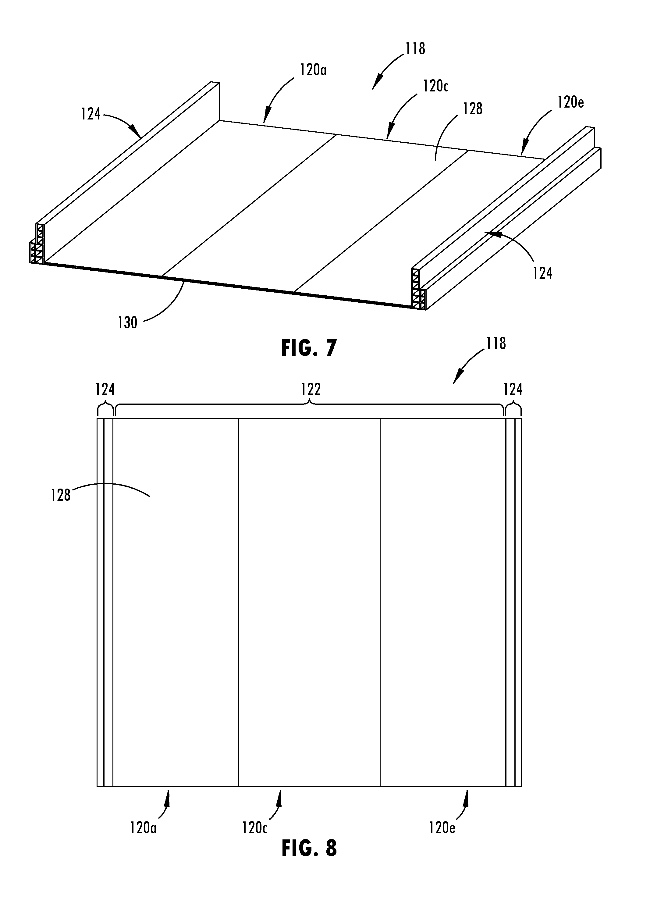
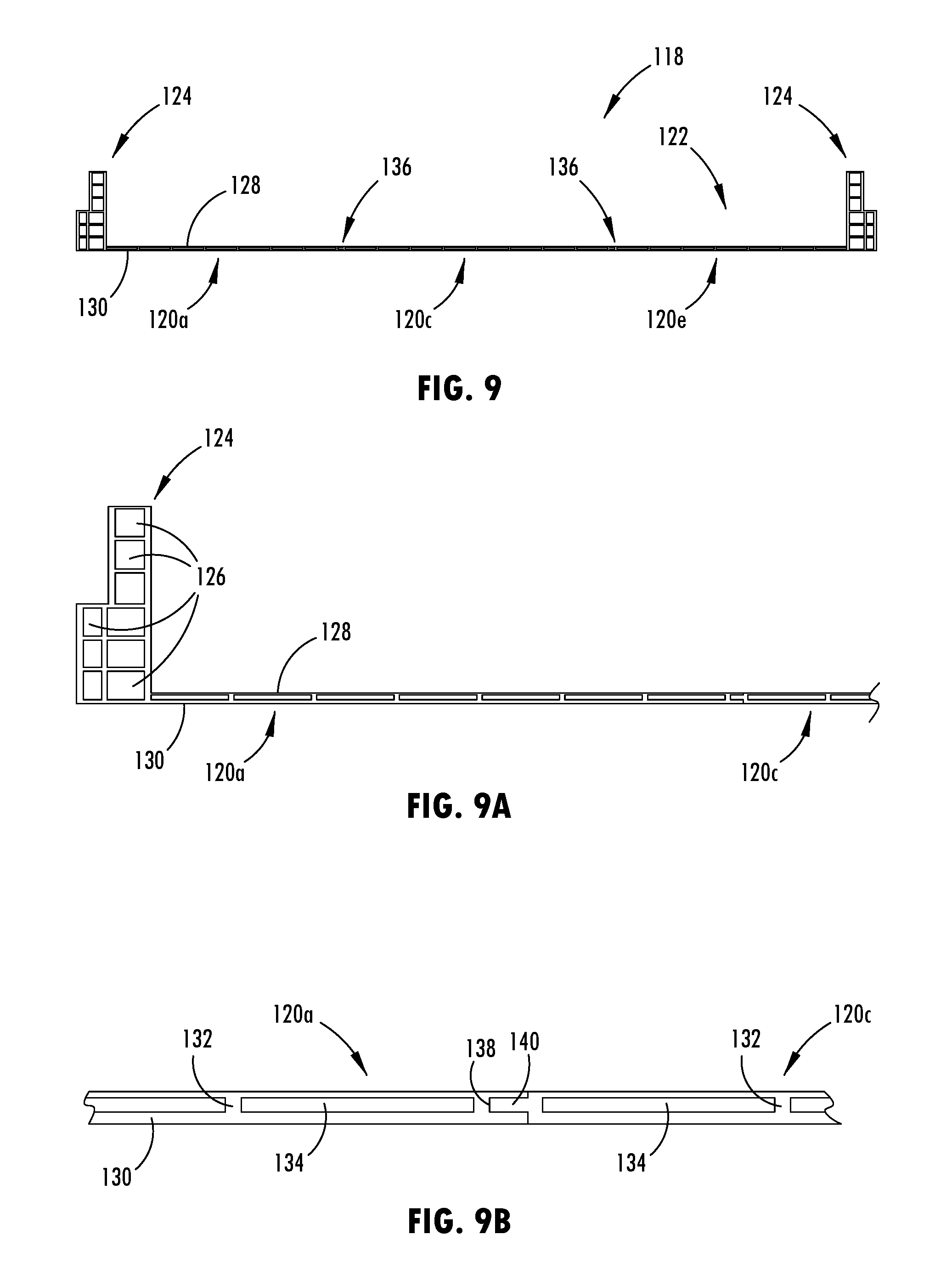
[0048] Referring now to an additional example shown in FIGS. 7-10, the battery tray floor assembly 118 has a floor structure 122 with a generally consistent thickness. As shown in FIG. 9B, the attachment feature 136 of one tray section 120a includes a channel 138 that extends longitudinally along an inside edge portion of the tray section 120a. The channel 138 may be generally defined between the upper and lower panel portions 128, 130 so as to be spaced at a generally central vertical location. Accordingly, the attachment feature 136 of the tray section 120c adjacent to the exterior tray section 120a may include a protrusion 140 that protrudes laterally from a generally central vertical location on the edge portion of the tray section 120c, and similarly the protrusion 140 may consistently extend longitudinally along the edge portion. The shape of the protrusion 140, such as the thickness and lateral extension, is generally configured to mate and engage with the channel 138 in a close or tight fitting manner, and thus it is contemplated that various protrusion and channel shapes are contemplated.
[0049] When engaged, the upper and lower surfaces of the adjacent tray sections 120a, 120c, 120e are generally aligned and flush, as shown in FIGS. 9-9B. The attachment features 136 may provide both a structural connection for interlocking the tray sections and a tight fitting or seal that is configured to prevent moisture intrusion into the containment area of the battery tray. In addition to or in the alternative to the mechanical interface provided by the engaged attachment features, it is contemplated that the interface between the tray sections may be attached with welding, adhesive, and/or fasteners or the like. As shown in FIGS. 6-8, one of the exterior tray sections 120a, 120e may be attached to the interior tray section 120c via the matting of the attachment features 136, and subsequently or simultaneously, the remaining exterior tray section may be attached to the opposing side of the interior tray section 120c via the corresponding attachment features 136. During or after interlocking or engaging the attachment features 136 together, such as with the protrusion 140 disposed in the channel 138, the additional engagement features, such as welding, adhesive, and/or fasteners or the like may be disposed at the connection. Features of the tray floor assembly 118 that are similar to the battery tray floor assembly 18 described above may not be described in detail again, and similar reference numbers may be used, incremented by 100.
[0050] Referring now to an additional example shown in FIG. 11, the battery tray floor assembly 218 has a floor structure with a varied thickness, where an inner tray section 220b has a greater thickness than an exterior tray section 220a, such that a central area of the floor portion of the battery tray is configured to support the loads distributed by the batteries contained in the battery tray. The illustrated the exterior and inner tray sections 220a, 220b each have an upper panel portion 228 and a lower panel portion 230 that are separated from each other by intermediate members 232 that interconnect the upper and lower panel portions 228, 230 and consistently extend longitudinally along the length of the respective tray section. Also, hollow areas 234 are defined between the upper and lower panel portions 228, 230 that also extend longitudinally along the intermediate members 232, so as to laterally separate the intermediate members 232 from each other and vertically separate the upper and lower panel portions 228, 230 from each other. The vertical separation provided by the intermediate members 232 at inner tray section 220b is greater than the vertical spacing provided at exterior tray section 220a.
[0051] With further reference to FIG. 11, the tray sections 220a, 220b are attached together using an attachment feature 236 that engages and couples with a corresponding attachment feature 236 of an adjacent tray section at a longitudinal seam between the tray sections. The illustrated attachment feature of the inner tray section 220b includes a protrusion 240 that protrudes generally laterally outward from the edge portion of the tray section 220b and that extends longitudinally along the edge portion of the tray section 220b. The corresponding edge portion of the exterior tray section 220a has a lower surface that rests on an upper surface of the protrusion 240 to provide the engagement between the adjacent tray sections 220a, 220b. The interface between the upper and lower surfaces at the respective protrusion 240 and engagement feature 236 of the exterior tray section 220a may be used for additional attachment means, such as welding, adhesive, and/or fasteners or the like. Features of the tray floor assembly 218 that are similar to the battery tray floor assembly 18 described above may not be described in detail again, and similar reference numbers are used, incremented by 200.
[0052] A further example is shown in FIG. 12, where the battery tray floor assembly 318 has a varied cross-sectional thickness. Specifically, an inner tray section 320c has a greater thickness than exterior tray sections 320a. The illustrated exterior tray section 320a has a tapering thickness that decrease at a generally consistent rate or slope from the inner tray section 320c toward an integrally formed wall portion of the exterior tray sections 320a. The floor portion of the illustrated tray sections 320a, 320c each have an upper panel portion 328 and a lower panel portion 330 that are separated from each other by intermediate members 332 that interconnect the upper and lower panel portions 328, 330 and consistently extend longitudinally along the length of the respective tray section. Also, hollow areas 334 are defined between the upper and lower panel portions 328, 330, such that the intermediate members 332 laterally separate the hollow areas 334 from each other and vertically support the upper and lower panel portions 328, 330 from each other.
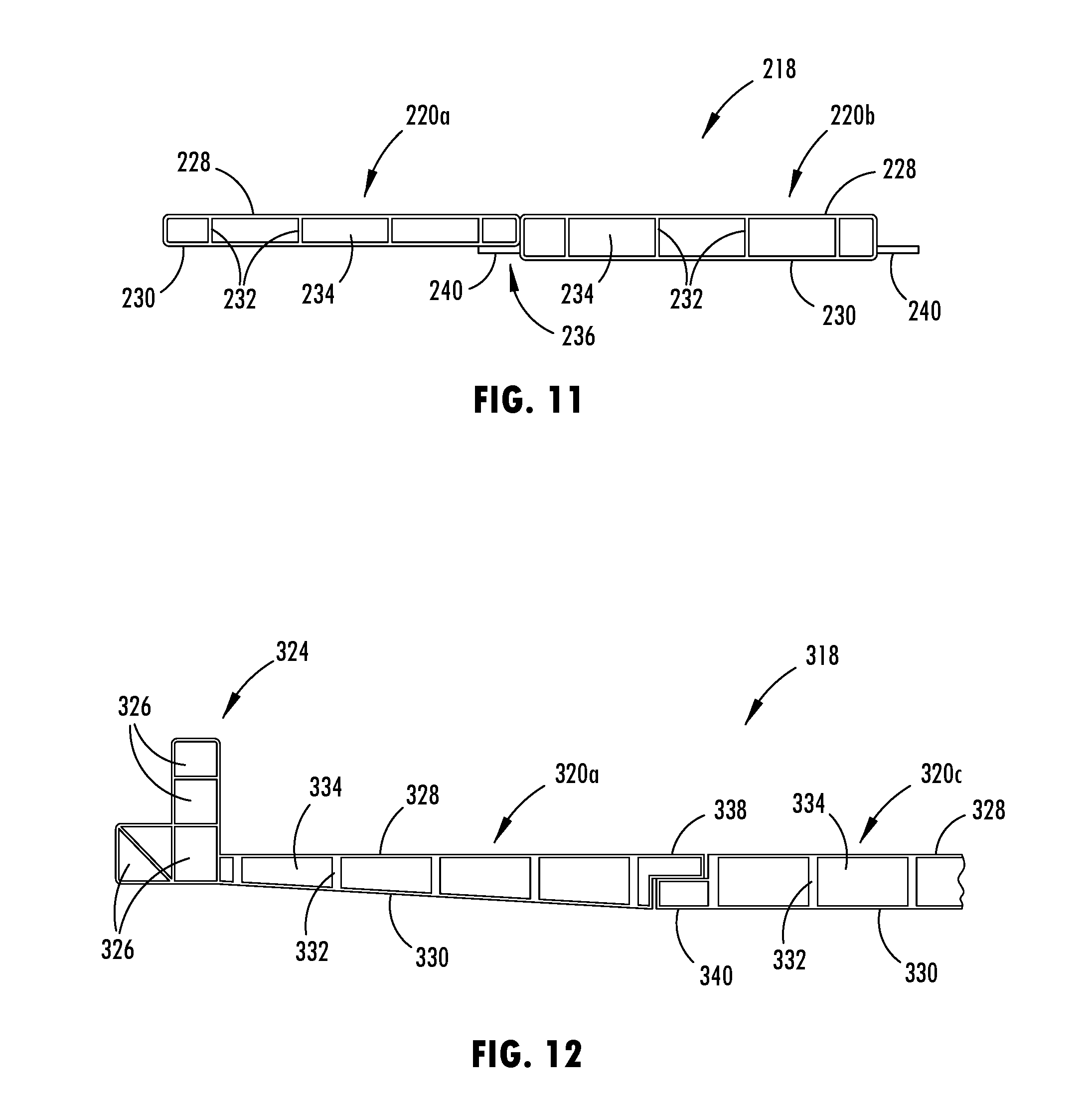
[0053] The exterior tray section 320a, as shown in FIG. 12, includes a wall portion 324 formed at an outer edge area of the floor portion of the exterior tray section 320a and that includes an upright interior surface extending integrally from the upper surface of the upper panel portion 328 of the exterior tray section 320a. It is understood that an additional exterior tray section may be attached at the opposing edge of the inner tray section 320c from the exterior tray section 320a shown in FIG. 12. The wall portions 324 of such an embodiment also include hollow areas 326 extending longitudinally along the exterior tray section 320a to provide a tubular structure that may function as a side reinforcement member of the battery tray that is configured to absorb and prevent intrusion from lateral impact forces to the vehicle. The exterior tray section 320a of the floor portion 322 shown as a single integral pieces of the parts that are of shown separately in FIGS. 3-6 as the intermediate tray sections 20b, 20d and the exterior tray section 20a, 20e of the floor assembly 18. Features of the tray floor assembly 318 that are similar to the battery tray floor assembly 18 described above may not be described in detail again, and similar reference numbers are used, incremented by 300.
[0054] As also illustrated in FIG. 12, the tray sections attach together using an attachment feature 336 that engages and couples with a corresponding attachment feature 336 of an adjacent tray section at a longitudinal seam between the tray sections. The illustrated attachment feature of the inner tray sections 320b include a lower protrusion or flange 340 that protrudes laterally from a lower edge portion of the tray section 320c and that extends longitudinally along the edge portion of the tray section. The corresponding edge portion of the exterior tray section 320a has an upper protrusion or flange 338 that extends from an upper edge portion of the tray section 320a and that rests on an upper surface of the flange 340 to provide the engagement between the adjacent tray sections. The interface between the respective flanges 338, 340 may include additional attachment means, such as welding, adhesive, and/or fasteners or the like.
[0055] When forming the tray sections of the battery tray floor assembly, the adjacent tray sections may be formed together, such as by a single extrusion die, so as to increase tray section production speed and the ease of assembly, among other benefits. For example, extrusion dies may be limited in size or diameter, such as to approximately 12 to 16 inches, whereby it may be desirable to package multiple tray sections into a single extrusion die. When in an initially formed state, at least two of the tray sections may thereby be integrally interconnected with each other, such that one or more interconnecting pieces or portions may be deformed to align and attach the tray sections and/or may be removed so as to allow the tray sections to subsequently attach together.
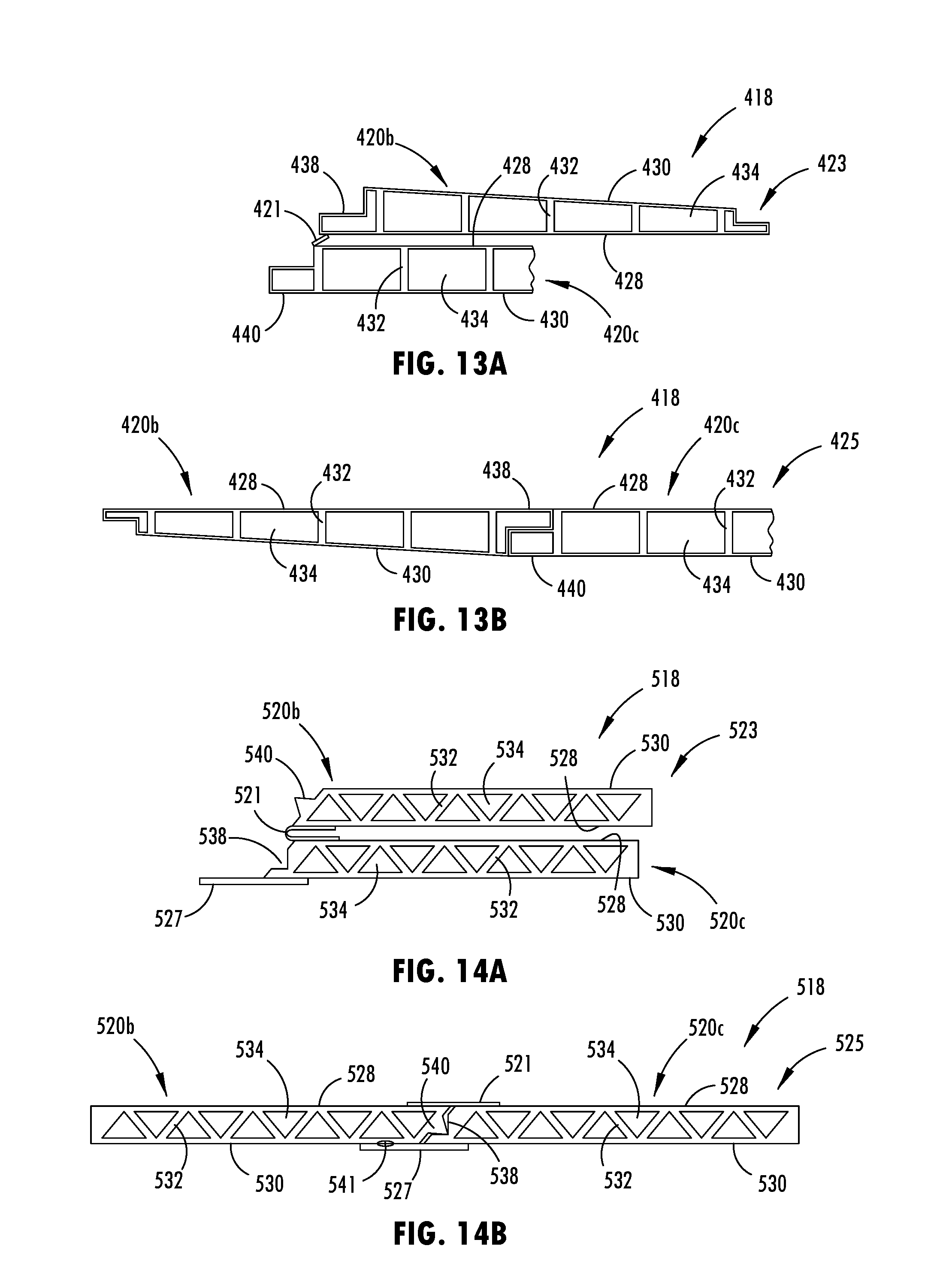
[0056] As shown in FIGS. 13A and 13B, an outer tray section 420b is extruded simultaneously with an inner tray section 420c with an interconnecting piece 421 connecting between the edge portions at the upper panel portions 428 of each tray section 420b, 420c and extending longitudinally along the tray sections. With the interconnecting piece 421 intact, as shown in FIG. 13A, the tray sections may be considered to be in an initially formed state 423. From the initially formed state 423, the interconnecting piece 421 may be cut from or otherwise removed from the edge portions of both try sections, such that the tray sections may then be attached, similar to the tray sections 20b, 20d shown in FIGS. 3-6 and described herein. When attached, the tray sections may be considered to be in a use state 425 forming a substantially planar structure that is configured to support vehicle batteries. Features of the tray floor assembly 418 that are similar to the battery tray floor assembly 18 described above may not be described in detail again, and similar reference numbers are used, incremented by 400.
[0057] Moreover, as shown in FIGS. 14A and 14B, an outer tray section 520b is extruded simultaneously with an inner tray section 520c with an interconnecting piece 521 connecting between the edge portions at the upper panel portions 528 of each tray section 520b, 520d and extending longitudinally along the tray sections. With the interconnecting piece 521 intact and shown in a U-shaped configuration, as shown in FIG. 14A, the tray sections may be considered to be in an initially formed state 523. From the initially formed state 523, the interconnecting piece 521 may be deformed from the U-shape to a generally flat configuration in alignment with the upper surfaces of the upper panel portions 528 of the tray sections, such that the tray sections are in substantially planar alignment with each other. As the deformation is occurring, attachment features along the edge portions of the tray sections 520b, 520c may engage with each other, such as a protrusion 540 engaging a corresponding channel 538. Once the interconnecting piece 521 is deformed to a planar configuration as shown in FIG. 14B, a lower brace 527 that protrudes form a lower panel portion of one of the tray sections may contact the adjacent lower panel of the other panel portion. The lower brace 527 may also be used as a weld point 541, such as with a laser welder or the like. When deformed and attached together, the tray sections may be considered to be in a use state 525 forming a substantially planar structure that is configured to support vehicle batteries, such as shown and described herein. Features of the tray floor assembly 518 that are similar to the battery tray floor assembly 18 described above may not be described in detail again, and similar reference numbers are used, incremented by 500.
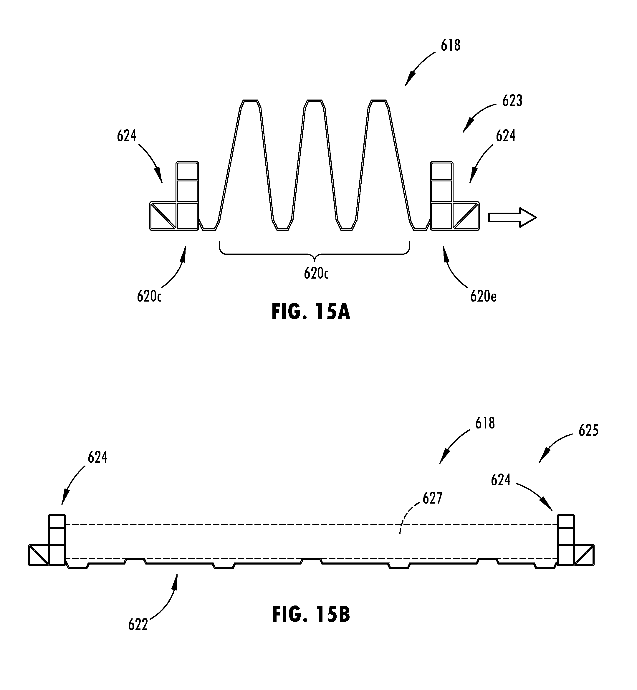
[0058] Furthermore, additional tray sections may be integrally formed together, such as all the tray sections of a single tray assembly 618, as shown in FIGS. 15A and 15B. In the initially formed state 623, the exterior tray sections 620a, 620e are integrally formed with wall portions 624 that each includes a hollow area extending longitudinally along the exterior tray section to provide a side reinforcement member of the battery tray. Also, multiple inner tray sections 620c are integrally formed with a cross-sectional profile that has a serpentine or wave-like shape that is generally consistent longitudinally along the length of the tray sections. The tray sections, such as the illustrated inner tray sections 620c, are deformed from the initially formed state 623 to a use state by laterally displacing the exterior tray sections, such as in a stretch forming apparatus and/or press to form a substantially planar floor structure 622 as shown in FIG. 15B. To further support and reinforce the floor portion 622 of the tray floor assembly 619, one or more cross members 627 may be disposed laterally between the wall portions 624 of the side reinforcement members. It is also shown that the floor structure 622 of the tray floor assembly 618 may include longitudinal stiffeners that include upward and downward facing channels integrally formed into the cross-sectional profile so as to extending longitudinally along the floor portion of the tray. Features of the tray floor assembly 618 that are similar to the battery tray floor assembly 18 described above may not be described in detail again, and similar reference numbers are used, incremented by 600.
[0059] Once the tray floor assembly is formed, it may be trimmed to accommodate the perimeter shape of the battery tray, such as shown in FIG. 16. A similar tray perimeter is shown in FIG. 2 in an example of the completed tray 10. In FIG. 16, the tray floor assembly is shown at the left with a thickness of 2 millimeters at the exterior tray sections and a thickness of 5 millimeters at a central tray section 820b. Thus, when pieces 850, 851 are trimmed from the tray floor assembly 818, they are taken from the exterior tray sections 820a, 820c, such that the mass of material removed is less than if the tray floor were monolithic, having a single thickness greater than 2 millimeters over the entire panel, such as shown to the right in FIG. 16 as a thickness of 4 millimeters. It is also contemplated that the exterior tray sections may have a shorter longitudinal length than the corresponding central tray section, so that the pieces that need to be trimmed are reduced in size.
[0060] Optionally, the battery tray floor assembly may be formed to arrange the tray sections in a manner that they extend laterally relative to vehicle, such that the tray section have a substantially constant cross-sectional profile laterally across the battery tray, such as the floor assembly 718 shown in FIGS. 17-20. In this embodiment, the tray sections may be engineered to have desired load capacity and performance for locating the batteries at the desired longitudinal position on the battery tray. Accordingly, the tray floor assembly 718 provides at least two separate tray sections 720e, 720f that are formed to each have a cross-sectional profile that is substantially consistent laterally across the width of the battery tray. This generally consistent profile each tray section may be formed by extrusion, such as with an aluminum alloy, or pultrusion, such as with a resin and composite substrate. Similar to the embodiments described above, the adjacent tray sections may be attached together, such as with engagement features that include one or more of mechanically engaged geometric features, such as protrusions and channels, welding, adhesive, fasteners and the like. The tray sections shown in FIGS. 17-20 also include intermediate wall portions 724 that protrude upward from the edges of the respect floor portions 722. Further, the upper surface of the illustrated floor portions 722 may include upward facing channels. Features of the tray floor assembly 718 that are similar to the battery tray floor assembly 18 described above may not be described in detail again, and similar reference numbers are used, incremented by 700.
[0061] Several different attachment techniques and configurations may be used to permanently or releasable secure the battery tray to a vehicle frame, such as below a floor of the vehicle and generally between the axles. Further, with respect to the general installation or attachment or formation, the steps discussed herein may be performed in various different sequences from those discussed to result in engaging, disengaging, or forming the battery tray or components thereof.
[0062] It is to be understood that the specific devices and processes illustrated in the attached drawings, and described in this specification are simply exemplary embodiments of the inventive concepts defined in the appended claims. Hence, specific values and other precise physical characteristics relating to the embodiments disclosed herein are not to be considered as limiting, unless the claims expressly state otherwise.
[0063] Changes and modifications in the specifically described embodiments may be carried out without departing from the principles of the present disclosure, which is intended to be limited only by the scope of the appended claims as interpreted according to the principles of patent law. The disclosure has been described in an illustrative manner, and it is to be understood that the terminology which has been used is intended to be in the nature of words of description rather than of limitation. Many modifications and variations of the present disclosure are possible in light of the above teachings, and the disclosure may be practiced otherwise than as specifically described.
* * * * *
D00000
D00001
D00002
D00003
D00004
D00005
D00006
D00007
D00008
D00009
D00010
D00011
D00012
D00013

XML
uspto.report is an independent third-party trademark research tool that is not affiliated, endorsed, or sponsored by the United States Patent and Trademark Office (USPTO) or any other governmental organization. The information provided by uspto.report is based on publicly available data at the time of writing and is intended for informational purposes only.
While we strive to provide accurate and up-to-date information, we do not guarantee the accuracy, completeness, reliability, or suitability of the information displayed on this site. The use of this site is at your own risk. Any reliance you place on such information is therefore strictly at your own risk.
All official trademark data, including owner information, should be verified by visiting the official USPTO website at www.uspto.gov. This site is not intended to replace professional legal advice and should not be used as a substitute for consulting with a legal professional who is knowledgeable about trademark law.