Cosmetic Container
BYEON; Jae Sam
U.S. patent application number 16/085485 was filed with the patent office on 2019-04-04 for cosmetic container. This patent application is currently assigned to KR CO., LTD. The applicant listed for this patent is KR CO., LTD.. Invention is credited to Jae Sam BYEON.
| Application Number | 20190098985 16/085485 |
| Document ID | / |
| Family ID | 59850987 |
| Filed Date | 2019-04-04 |

| United States Patent Application | 20190098985 |
| Kind Code | A1 |
| BYEON; Jae Sam | April 4, 2019 |
COSMETIC CONTAINER
Abstract
In an embodiment, a cosmetic container is provided. The cosmetic container may include a storage container for receiving cosmetics, a pump support part coupled to the storage container and having a groove part at a central area, a pump part inserted in the groove part and having a rod protruding towards an upper part of the groove part, and a discharge plate provided on an upper part of the pump support part and having at least one discharge hole discharging the cosmetics. Due to a press motion of the discharge plate, a lower part surface of the discharge plate may press down on the rod, leading to a pumping action of the pump part.
| Inventors: | BYEON; Jae Sam; (Yangpyeong-gun, Gyeonggi-do, KR) | ||||||||||
| Applicant: |
|
||||||||||
|---|---|---|---|---|---|---|---|---|---|---|---|
| Assignee: | KR CO., LTD Bucheon-si, Gyeonggi-do KR |
||||||||||
| Family ID: | 59850987 | ||||||||||
| Appl. No.: | 16/085485 | ||||||||||
| Filed: | June 10, 2016 | ||||||||||
| PCT Filed: | June 10, 2016 | ||||||||||
| PCT NO: | PCT/KR2016/006211 | ||||||||||
| 371 Date: | September 14, 2018 |
| Current U.S. Class: | 1/1 |
| Current CPC Class: | B65D 47/00 20130101; A45D 40/0075 20130101; A45D 40/222 20130101; A45D 2200/054 20130101; A45D 2040/223 20130101; A45D 33/06 20130101; B65D 83/00 20130101; B65D 83/0044 20130101; A45D 33/04 20130101 |
| International Class: | A45D 40/00 20060101 A45D040/00; A45D 40/22 20060101 A45D040/22; B65D 83/00 20060101 B65D083/00 |
Foreign Application Data
| Date | Code | Application Number |
|---|---|---|
| Mar 17, 2016 | KR | 10-2016-0032003 |
Claims
1. A cosmetic container, comprising: a storage container for receiving cosmetics; a pump support part coupled to the storage container and having a groove part at a central area; a pump part inserted in the groove part and having a rod protruding toward an upper part of the groove part; and a discharge plate on an upper part of the pump support part and having at least one discharge hole through which the cosmetics are discharged, wherein due to a press motion of the discharge plate, a lower part surface of the discharge plate presses down on the rod and a pumping action of the pump part is realized.
2. The cosmetic container of claim 1, wherein the rod includes a convex end part touching the lower part surface of the discharge plate.
3. The cosmetic container of claim 2, wherein an area touching the rod among the lower part surface of the discharge plate has a concave area which corresponds to the convex end part.
4. The cosmetic container of claim 1, wherein at least one protruding part is formed at least at one area of outside of the discharge plate and at least one guide groove in which the protruding part is inserted is formed on an inner circumferential surface of an edge of the pump support part.
5. The cosmetic container of claim 4, wherein the guide groove restricts an upward movement of another area of the discharge plate which occurs when a press motion occurs in one area of the discharge plate.
6. The cosmetic container of claim 5, wherein a non-slip projection protruding towards a central direction of the pump support part is formed on an upper end of the dent area to restrict an upward movement of another area of the discharge plate that occurs when there is a press motion in one area of the discharge plate.
7. The cosmetic container of claim 4, wherein a dent area where the protruding part is inserted in the guide groove extends toward a lower part of the inner circumferential surface of the edge and one area of the discharge plate moves downward according to a press motion of the discharge plate.
8. The cosmetic container of claim 1, further comprising at least one elastic member between the discharge plate and the pump support part and restoring a position of the discharge plate that is changed by the press motion.
9. The cosmetic container of claim 1, wherein the discharge plate is exposed to outside such that a puff of a user may be contacted.
10. A cosmetic container comprising: a storage container for receiving cosmetics; a pump support part coupled to the storage container and having a groove part at a central area; a pump part inserted in the groove part; and a discharge plate provided on the pump support part and having at least one discharge hole through which the cosmetics are discharged, wherein at least one protruding part is formed in at least one area outside the discharge plate and at least one guide groove in which the protruding part is inserted is formed in an inner circumferential surface of an edge of the pump support part.
11. The cosmetic container of claim 10, wherein the guide groove restricts an upward movement of another area of the discharge plate that occurs when there is a press motion in one area of the discharge plate.
12. The cosmetic container of claim 11, wherein a non-slip projection protruding towards a central direction of the pump support part on an upper end of the dent area is formed to restrict an upward movement of another area of the discharge plate that occurs when there is a press motion in one area of the discharge plate.
13. The cosmetic container of claim 10, wherein a dent area where the protruding part is inserted in the guide groove extends to the lower part of the inner circumferential surface of the edge, and according to a press motion of the discharge plate, one area of the discharge plate moves to the lower part.
Description
TECHNICAL FIELD
[0001] The present invention relates to a cosmetic container. The cosmetic container may evenly discharge cosmetics regardless of where pressure is applied.
BACKGROUND ART
[0002] Cosmetics are categorized into solid, liquid or gel-like makeup products depending on the form. Recently, more consumers have shown their interest in the gel-like makeup products which have long persistence and good fit and feel when applied on skin. However, conventional containers for gel-like makeup products as used by consumers require that the gel-like makeup products be inserted into a glass or tube container and thereafter consumers squeeze or take out gel-like makeup products into hands or puff and apply on the skin. However, consumers have to wash their hands after taking out or squeezing out the cosmetics into their hands, making the use of the conventional gel-like makeup product containers uncomfortable, and also, it is difficult to uniformly distribute the gel-like makeup products on puff.
[0003] In order to overcome the problem, Registered Utility Model No. 20-0470757 discloses a compact container having an airless pump. Registered Utility Model No. 20-0470757 discloses the cosmetic filled in the container body being uniformly discharged on a distribution member by the user's pressing the distribution member and the pump.
[0004] However, according to Registered Utility Model No. 20-0470757, the pump is located at a central part of the distribution member, and thus only if a user presses vertically the central part of the distribution member, the pump will operate and thus the cosmetics is discharged.
[0005] Therefore, a technique for solving such problems is needed.
DETAILED DESCRIPTION OF INVENTION
[0006] Technical Problem
[0007] The present invention has been made to solve the above-mentioned problems. The present invention is related to a cosmetic container which, even if a peripheral part is pressed, not a central part of the discharge plate, a pressure will be transmitted to a pump, and cosmetics are evenly discharged.
Technical Solution
[0008] In an embodiment, a cosmetic container may include a storage container for containing cosmetics, a pump support part coupled to the storage container and having a groove part at a central area, a pump part inserted in the groove part and having a rod protruding to an upper part of the groove part, a discharge plate provided on the upper part of the pump support part and having at least one discharge hole through which the cosmetics are discharged, wherein a pumping action of the pump part occurs as a lower part surface of the discharge plate presses down on the rod due to a press motion of the discharge plate.
[0009] In an embodiment, the rod may include a convex end part touching a lower part surface of the discharge plate.
[0010] In an embodiment, a concave area that corresponds to the convex end part may be provided in an area that touches the rod among the lower part surface of the discharge plate.
[0011] In an embodiment, at least one protruding part may be provided in at least one area outside of the discharge plate, and at least one guide groove in which the protruding part is inserted may be provided in an inner circumferential surface of an edge of the pump support part.
[0012] In an embodiment, the guide groove may restrict an upward movement of another area of the discharge plate which occurs when a press motion occurs in one area of the discharge plate.
[0013] In an embodiment, a non-slip projection protruding towards a central direction of the pump support part may be provided in an upper end of a dent area such that an upward movement of another area of the discharge plate which occurs upon occurrence of a press motion in one area of the discharge plate is restricted.
[0014] In an embodiment, in the guide groove, a dent area where the protruding part is inserted extends downwards of the inner circumferential surface of the edge, and according to a pressing action of the discharge plate, one area of the discharge plate can move downwards.
[0015] In an embodiment, at least one elastic member that restores a location of the discharge plate that has changed as a result of the press motion may be further provided between the discharge plate and the pump support part.
[0016] In an embodiment, the discharge plate may be exposed to outside such that puff of a user can be in contact with the discharge plate.
[0017] In an embodiment, a cosmetic container may include a storage container for receiving cosmetics, a pump support part coupled to the storage container and having a groove part at a central area, a pump part inserted inside the groove part, and a discharge plate provided on the pump support part and having at least one discharge hole through which the cosmetics are discharged. At least one protruding part may be formed at least in one area outside the discharge plate, and at least one guide groove where the protruding part is inserted in an inner circumferential surface of an edge of the pump support part.
[0018] In an embodiment, the guide groove may restrict an upward movement of another area of the discharge plate that occurs when there is a press motion in one area of the discharge plate.
[0019] In an embodiment, a non-slip projection that protrudes towards a central direction of the pump support part may be provided on an upper end of the dent area in order to restrict an upward movement of another area of the discharge plate that occurs when a press motion takes place in one area of the discharge plate.
[0020] In an embodiment, a dent area where the protruding part is inserted in the guide groove extends downward of the inner circumferential surface of the edge. According to the press motion of the discharge plate, one area of the discharge plate may move downward.
Advantageous Effects
[0021] According to the present invention, even if any area of the discharge plate is pressed, slanting of a discharge plate is minimized and a pressure force is transmitted to a pump part, and therefore cosmetics may be easily discharged.
[0022] In addition, according to the present invention, a rod of a pump part to which a pressure is transferred is provided at a central area of a discharge plate. Accordingly, the difference in force being transferred depending on the location where the pressure is applied by a user may be minimized.
[0023] Furthermore, the shape of an end part of a rod and the shape of a discharge plate that touches the end part of the rod may correspond to each other. Accordingly, the discharge plate may transfer the pressure to a rod in a stable manner and at the same time make downward movement and slanting of the discharge plate smooth and gradual, thereby enhancing the feel and experience by users when they use the present invention.
BRIEF DESCRIPTION OF THE DRAWINGS
[0024] Brief description on each drawing figure will be provided so that the drawing figures referenced in the detailed description may be more sufficiently understood.
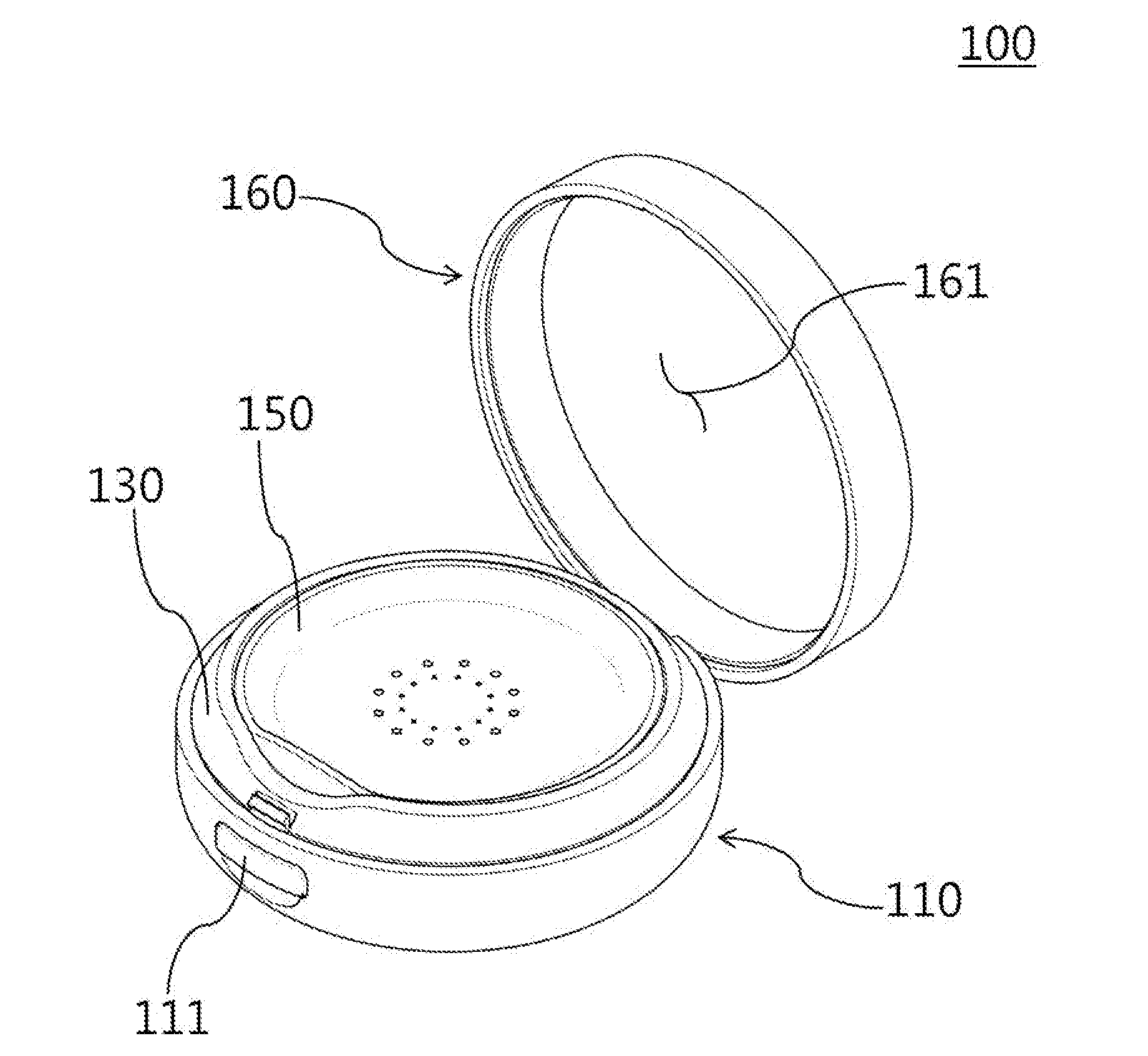
[0025] FIG. 1 illustrates a cosmetic container according to an embodiment.
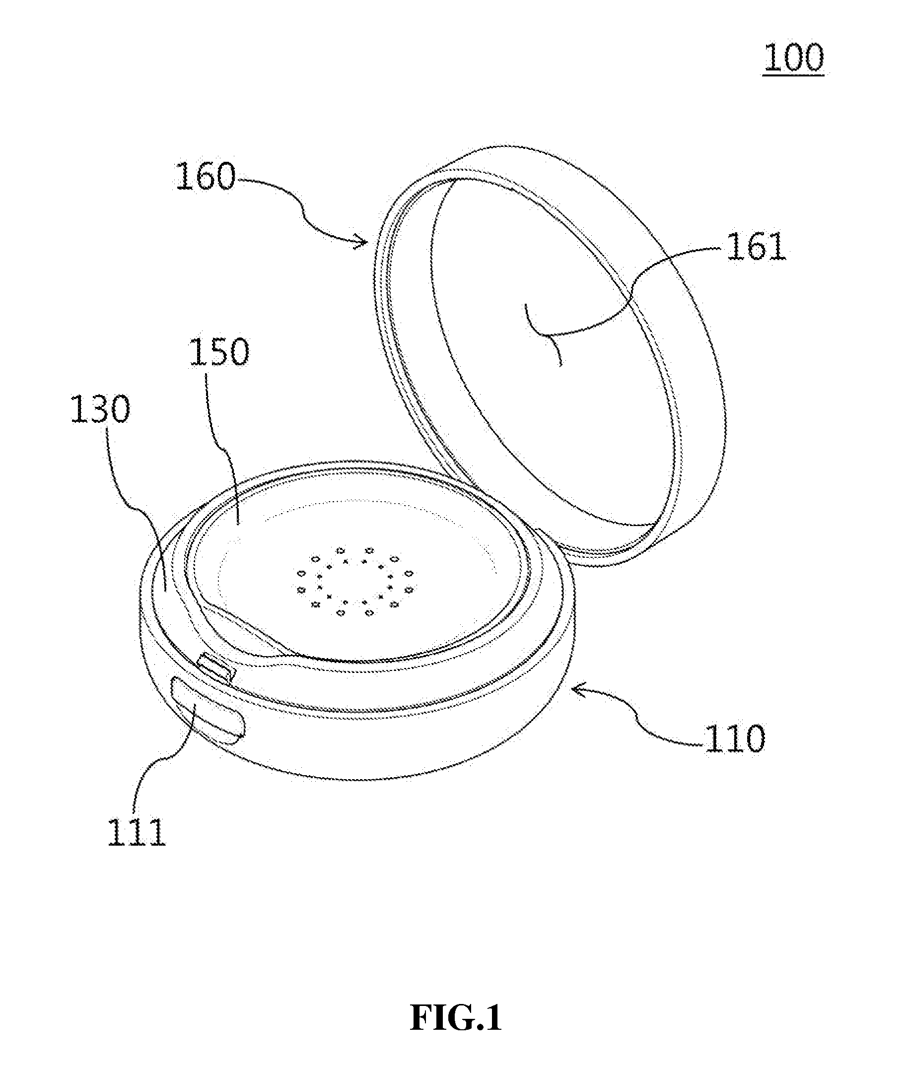
[0026] FIG. 2 is an exploded perspective view of a cosmetic container according to an embodiment.
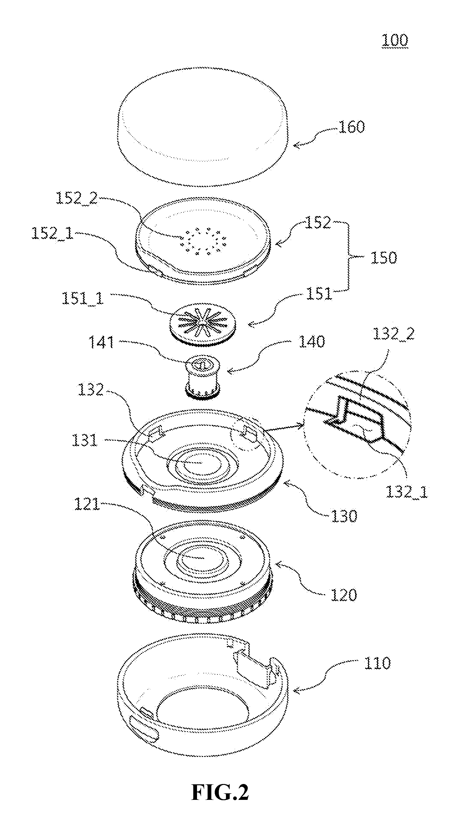
[0027] FIG. 3 illustrates a pump part of a cosmetic container according to an embodiment.
[0028] FIG. 4 is a cross sectional view of a cosmetic container according to an embodiment.
[0029] FIG. 5 illustrates a shape of a rod of a pump part according to an embodiment.
[0030] FIG. 6 illustrates a shape of a rod of a pump part according to an embodiment.
[0031] FIG. 7 illustrates a shape of a pump support part according to an embodiment.
MODE FOR INVENTION
[0032] Hereinafter, example embodiments will be described with reference to the accompanying drawings; however, for reference numerals, with respect to the same elements, even though they may be displayed in different drawings, such elements use same reference numerals as much as possible. Also, in explaining the example embodiments, detailed description on known elements or functions will be omitted if it is determined that such description will interfere with understanding of the embodiments. In addition, the example embodiments may be embodied in different forms and should not be construed as limited to the embodiments set forth herein but may be modified and variously implemented by those skilled in the art.
[0033] In the drawing figures, dimensions may be exaggerated for clarity of illustration. It will be understood that when an element is referred to as being "between" two elements, it can be the only element between the two elements, or one or more intervening elements may also be present. It will be understood that when a part includes or has an element, it does not mean that other elements are excluded but that other elements may be further included. Also, in explaining elements, terms like "first", "second", "A", "B", "(a)", "(b)", etc. may be used. However, such terms are used to distinguish one from the others only and they do not affect the essence, nature, sequence, order, etc.
[0034] FIG. 1 illustrates a cosmetic container according to an embodiment.
[0035] Referring to FIG. 1, an outer case of a cosmetic container 100 according to an embodiment may include a lower case 110 and an upper case 160. The lower case 110 may receive a storage container 120, a pump support part 130, a pump part 140 and a discharging plate 150 on the inside. Outside the lower case 110, there may be a button part 111 having a non-slip bump in one area and a hinge part (not shown) that is hinge-coupled to an upper case in another area. The button part 111 may cause the upper case 160 to break away from the non-slip bump as the non-slip bump that is extended to an upper part of the button part recedes due to a press motion of a user.
[0036] An upper case 160 may be hinge-coupled to a lower case 110 and may open or close the lower case 110 to or from outside. In addition, a mirror, etc. may be provided on an inner circumferential surface of an upper case 160, which makes use of the cosmetic container 100 easier.
[0037] FIG. 2 is a perspective view illustrating a cosmetic container according to an embodiment.
[0038] Referring to FIG. 2, a cosmetic container 100 may include a storage container 120, a pump support part 130, a pump part 140 and a discharge plate 150.
[0039] The storage container 120 receives cosmetics, and there may be a receiving groove 121 at a central area. A connecting part connecting with a cosmetic storage space of the storage container 120 may be formed at a lower part of the receiving groove 121, and the cosmetics may be discharged to outside via the connecting part. The cosmetics received in the storage container 120 may be selected from liquid sun cream, liquid powder, BB cream, lotion or cream, but is not limited thereto; various liquid cosmetics can be accommodated according to an embodiment.
[0040] A pump support part 130 may support a pump part 140, and at the same time, be coupled to a storage container 120. As such, a groove part 131 having a predetermined depth may be formed at a central area of the pump support part 130, and the pump part 140 may be provided in the groove part 131. In addition, the groove part 131 may be coupled to a receiving groove 121 of the storage container 120. For example, the coupling may be done by screw coupling along a screw line formed in the groove part 131 and/or receiving groove 121. However, this is for illustration purpose only, and the way of coupling is not limited thereto.
[0041] Furthermore, at least one guide groove 132 may be formed in an inner circumferential surface of an edge of the pump support part 130. In particular, the guide groove 132 may include a dent area 132_1 and a non-slip projection 132_2. The dent area 132_1 may be formed by denting of the inner circumferential surface of the edge of the pump support part 130 and may receive a protruding part 152_1 of the discharge plate 150 and at the same time may provide a downward movement space of the protruding part 152_1. In addition, the non-slip projection 132_2 may be formed on an upper end of the dent area 132_1 by the denting of the inner circumferential surface of the edge, and therefore the non-slip projection 132_2 may prevent the protruding part 152_1 of the discharge plate 150 from moving upward, and at the same time, a force may occur centered around the non-slip projection 132_2 which presses down on a rod 141 as the protruding part 152_1 is supported by the non-slip projection 132_2.
[0042] According to an embodiment, the number, position, size, etc. of the guide groove 132 formed in the pump support part 130 may vary. In other words, as illustrated in FIG. 2, if a dent area 132_1 and/or non-slip projection 132_2 is restricted to have a predetermined width, the movement of the protruding part 152_1 to the right or to the left will be limited and thus the loss of a pressing force from the rotation or turn of the discharge plate 150 may be prevented. Also, as to be further described with reference to FIG. 7, the dent area 132_1 and/or non-slip projection 132_2 may be formed over the entire inner circumferential surface of the edge. Here, the discharge plate 150 may also form at least one protruding part 152_1 in various positions.
[0043] The pump part 140 may discharge the cosmetics in the storage container 120 to outside via the discharge plate 150. The pump part 140 may be inserted in the groove part 131. Furthermore, a rod 141 protruding to an upper part of the groove part 131 may be formed at a central area of the pump part 140. When there is a press motion on the discharge plate 150, a lower part surface of the discharge plate 150 contacts and presses the rod 141, and a pumping motion of the pump part 140 may be performed. Detailed description on each element of the pump part 140 will be described below in more detail with reference to FIG. 3.
[0044] The discharge plate 150 may transmit a pressing force from a user to a pump part 140 and discharge cosmetics transferred by the pump part 140 to outside. The discharge plate 150 may include a lower plate 151 and an upper plate 152.
[0045] In particular, the lower plate 151 may be provided between the upper plate 152 and the pump part 140. The cosmetics transferred by the pump part 140 may move downward, below a discharge hole 152_2 of the upper plate 152 via a diffusion space formed between the lower plate 151 and the upper plate 152. For this process, a diffusion groove 151_1 having a radial shape, for example, which guides transfer of cosmetics, may be formed on a surface of the lower plate 151. The discharge hole 152_2 of the upper plate 152 may respectively be at an upper part of the diffusion groove 151_1. Furthermore, the lower plate 151 may be coupled to an upper end of the pump part 140 such that airtight sealing may be possible, and when the discharge plate 150 is pressed, the cosmetics being transferred from the pump part 140 to the lower plate 151 may be prevented from being exposed to outside.
[0046] The upper plate 152, when pressed by a user, may move downward and may press the rod 141 of the pump part 140. In particular, the upper plate 152 may be spaced from an upper part surface of the pump support part 130 at certain distance intervals and arranged, and at least one protruding part 152_1 capable of being inserted in the guide groove 132 of the pump support part 130 may be formed as protruding towards an outside direction in at least one area outside of the upper plate 152. The upper plate 152 may contact a puff of a user as the upper part surface is exposed to outside. There may be at least one discharge hole 152_2 through which cosmetic is discharged in one area of the upper part surface. Furthermore, to accommodate a puff, etc. of a user in a stable manner, a central area of the upper part surface of the upper plate 152 may have a dent shape which is dent towards inside. However, this is only an example, and the upper plate 152 may be realized in various different ways according to an embodiment.
[0047] FIG. 3 illustrates a pump part of a cosmetic container according to an embodiment.
[0048] Referring to FIG. 3, a pump part 140 may include a housing part 142, a check valve part 143, a piston rod 144, a guide piston 145, a first sealing part 146, a spring part 147 and a second sealing part 148.
[0049] A housing part 142 may include a storage space inside, and a through hole, through which cosmetic flows in, may be formed on a lower part surface. In other words, the housing part 142 may flow the cosmetics discharged from the storage container 120 into the pump part 140 via the through hole. As a piston rod 144 moves up and down, a space may be provided in which the pump part 140 can operate.
[0050] A check valve part 143 may be positioned on a lower end of the storage space of the housing part 142 and may open and close the through hole. In other words, the check valve part 143 may open or close the through hole depending on the downward or upward movement of the piston rod 144, thereby flowing cosmetics into the housing part 142 or block the inflow.
[0051] The piston rod 144 may be provided on an upper part of the check valve part 143 of a storage space of the housing part 142 and may include a cylinder formed outside and a rod 141 formed inside the cylinder. Here, at least one inflow hole may be formed on a surface of the cylinder such that cosmetics can be transferred from the check valve part 143 into the cylinder, and the rod 141, having received the pressure transferred from the discharge plate 150, may move the piston rod 144 downward. The piston rod 144 that has moved downward may be restored upward by an elastic force of the spring part 147. Also, an upper end of an inner circumferential surface of the cylinder may be coupled to at least one area of the lower part surface of the discharge plate 150 such that airtight sealing may be possible, and thus when there is a pumping motion of the pumping part 140, the cosmetics may be made not to be leaked to other external areas but only to the discharge plate 150.
[0052] The guide piston 145 may be closely provided between an inner side surface of the housing part 142 and an outer side surface of the piston rod 144 and may guide upward and downward movement of the piston rod 144. When there is a pumping motion of the piston rod 144, depending on the upward or downward movement of the piston rod 144, the guide piston 145 may be fixed and/or move along in piston rod 144 line therewith. Therefore, it may respectively couple to the piston rod 144 or form a certain interval space from the piston rod 144, cosmetics may be discharged from the check valve part 143 and move into the piston rod 144.
[0053] A first sealing part 146 may be fix-coupled to an upper part of a housing part 142 and seal the housing part 142 with a second sealing part 148. As a result, cosmetics may not be spilled to outside of the housing part 142, not going through the piston rod 144.
[0054] A spring part 147 may wrap around an outer circumference surface of the housing part 142 and may restore a position of the piston rod 144 that moved downward which changed due to user's pressing action. In other words, if pressing force is removed, the spring part 147 may move upward the second sealing part 148 coupled to the spring part 147. Here, the piston rod 144 coupled to the second sealing part 148 may together move upward, and the position of the piston rod 144 which changed due to pressure may be together restored.
[0055] The second sealing part 148 may be provided on an upper part of the first sealing part 146, and at least one area may be inserted such that an interval space between the first sealing part 146 and an outer surface of the cylinder of the piston rod 144 can be airtight sealed. The second sealing part 148 may be provided on an upper part of the spring part 147 and may move downward together when the piston rod 144 moves downward due to pressure from a user, compressing the spring part 147 thereby generating an elastic force. Thereafter, if a pressing force is removed, the position of the piston rod 144 may be restored by moving upward.
[0056] FIG. 4 is a cross-sectional view of a cosmetic container according to an embodiment.
[0057] In particular, FIG. 4(a) illustrates the discharge plate before being pressed, and FIG. 4(b) illustrates the discharge plate being pressed.
[0058] Referring to FIG. 4, a rod 141 is provided at a central area of the discharge plate 150. As a result, even if a user presses any area of the discharge plate 150, the difference in force that is transmitted to the rod 141 may be minimized.
[0059] In addition, if the central area of the discharge plate 150 is pressed, the discharge plate 150 may move downward without being slanted and press the rod 141. However, if a pressing motion takes place at a peripheral area of the discharge plate 150, the rod 141 may function as a central axis of a lever, and a torque in an opposite direction of the pressure may be acted on in an opposite area which is symmetrical to one area where a pressure is acted on, with respect to the rod 141. If the torque is not removed, even if the discharge plate 150 is pressed, the discharge plate 150 may only cause the rod 141 to be slanted towards an axis, and the pressure may not end up being transmitted to the rod 141.
[0060] In order to overcome the problem, in the present invention, an upward movement of the protruding part 152_1 inserted in a guide groove 132 of the pump support part 130 is restricted to a non-slip projection 132_2. That is, even if a torque is in action in an opposite area, the upward movement of the protruding part 152_1 located in the opposite area is restricted by the non-slip projection 132_2, and the non-slip projection 132_2 may offset the torque. Accordingly, the discharge plate 150 may slant downward with respect to the non-slip projection 132_2 as the center axis, the pressing force is transmitted to the rod 141, and the pump part 140 may operate. In addition, the dent area 132_1 of the guide groove 132 may extend downward from an insertion position of the protruding part 152_1, and the downward movement of the discharge plate 150 in the area where pressure acts on may be made possible.
[0061] As such, through the protruding part 152_1 and the guide groove 132, the slanting of the discharge plate 150 may be minimized. Accordingly, even if any area of the discharge is pressed, the discharge plate 150 may press the rod 141, thereby easily discharging the cosmetics.
[0062] In the meantime, at least one elastic member 170 may be provided between the discharge plate 150 and the pump support part 130. The elastic member 170 may restore the position of the discharge plate 150. After the pressing motion takes place, depending on the restoration of the state of the pump part 140, the rod 141, while moving upward, may not only restore the location and/or position of the discharge plate 150, but also the elastic member 170 may provide an elastic force towards an upper part if the discharge plate 150 is slanted or does not sufficiently rise by the rod 141, thereby readily assisting restoration of the location and/or position of the discharge plate 150.
[0063] FIG. 4 illustrates the rod 141 acting on as a central axis of a lever, but this is only an example, and different element/structure of the pump part 140 may function as a central axis of a lever according to an embodiment.
[0064] FIGS. 5 and 6 illustrate shapes of a rod of a pump part according to an embodiment. FIGS. 5(a) and 6(a) illustrate the discharge plate before being pressed, and FIGS. 5(b) and 6(b) illustrate the discharge plate being pressed.
[0065] In particular, referring to FIGS. 5 and 6, rods 141 and 141' may include a convex end part touching a lower part surface of upper plates 152 and 152', and there may be a concave area whose shape corresponds to the convex end part in an area touching the rods 141 and 141' among the lower part surfaces of the upper plates 152 and 152'. The convex end part and the concave area may be formed to have a gentle curve surface in at least one area. Accordingly, for example, if the upper plates 152 and 152' are slanted and press down on the rods 141 and 141', by increasing the touching surfaces of the rods 141 and 141' touching the upper plates 152 and 252, the pressing force is stably transferred to the lower direction of the rods 143 and 243, and at the same time, the slanting of the upper plates 152 and 152' may be made smoother in a gentle slope.
[0066] The shapes of the convex end part and the concave area are for illustrative purposes only, and as shown in FIGS. 5 and 6, the shapes of the convex end part and the concave area, for example, the degree of curvature or cutting may be realized in various different ways according to an embodiment.
[0067] FIG. 7 illustrates the shape of a pump support part according to an embodiment.
[0068] Referring to FIG. 7, one guide groove 132 may be formed in a pump support part 130. In other words, a dent area 132_1 and/or non-slip projection 132_2 of the guide groove 132 may be formed over the entire inner circumferential surface of the edge. Here, the discharge plate 150 may also form at least one protruding part 152_1 in various positions.
[0069] By simplifying the constitution of the guide groove 132 and protruding part 152_1, the manufacture is rendered easy and the process unit price is reduced, and thus the invention may be realized at a better economic cost.
[0070] Example embodiments have been disclosed herein, and although specific terms are employed, they are used and are to be interpreted in a generic and descriptive sense only and not for purpose of limitation. In some instances, as would be apparent to one of ordinary skill in the art as of the filing of the present application, features, characteristics, and/or elements described in connection with a particular embodiment may be used singly or in combination with features, characteristics, and/or elements described in connection with other embodiments unless otherwise specifically indicated. Accordingly, it will be understood by those of skill in the art that various changes in form and details may be made without departing from the spirit and scope of the present invention as set forth in the following claims.
* * * * *
D00000
D00001
D00002
D00003
D00004
D00005
D00006
XML
uspto.report is an independent third-party trademark research tool that is not affiliated, endorsed, or sponsored by the United States Patent and Trademark Office (USPTO) or any other governmental organization. The information provided by uspto.report is based on publicly available data at the time of writing and is intended for informational purposes only.
While we strive to provide accurate and up-to-date information, we do not guarantee the accuracy, completeness, reliability, or suitability of the information displayed on this site. The use of this site is at your own risk. Any reliance you place on such information is therefore strictly at your own risk.
All official trademark data, including owner information, should be verified by visiting the official USPTO website at www.uspto.gov. This site is not intended to replace professional legal advice and should not be used as a substitute for consulting with a legal professional who is knowledgeable about trademark law.