Imaging Lens And Optical Apparatus
NAGATOSHI; Yukiko ; et al.
U.S. patent application number 16/133038 was filed with the patent office on 2019-03-28 for imaging lens and optical apparatus. This patent application is currently assigned to FUJIFILM Corporation. The applicant listed for this patent is FUJIFILM Corporation. Invention is credited to Shunsuke MIYAGISHIMA, Yukiko NAGATOSHI, Kazuyoshi OKADA, Yasutaka SHIMADA, Ukyo TOMIOKA, Masaru YONEZAWA.
| Application Number | 20190094533 16/133038 |
| Document ID | / |
| Family ID | 65808821 |
| Filed Date | 2019-03-28 |


View All Diagrams
| United States Patent Application | 20190094533 |
| Kind Code | A1 |
| NAGATOSHI; Yukiko ; et al. | March 28, 2019 |
IMAGING LENS AND OPTICAL APPARATUS
Abstract
The imaging lens includes at least one negative lens that satisfies predetermined Conditional Expressions (1) to (3) indicating conditions in which dispersion is relatively low and refractive index is high while having a negative rate of change of the refractive index. A positive lens having a largest Abbe number at the d line among positive lenses included in the imaging lens satisfies predetermined Conditional Expressions (4) and (5).
| Inventors: | NAGATOSHI; Yukiko; (Saitama, JP) ; MIYAGISHIMA; Shunsuke; (Saitama, JP) ; OKADA; Kazuyoshi; (Saitama, JP) ; TOMIOKA; Ukyo; (Saitama, JP) ; YONEZAWA; Masaru; (Saitama, JP) ; SHIMADA; Yasutaka; (Saitama, JP) | ||||||||||
| Applicant: |
|
||||||||||
|---|---|---|---|---|---|---|---|---|---|---|---|
| Assignee: | FUJIFILM Corporation Tokyo JP |
||||||||||
| Family ID: | 65808821 | ||||||||||
| Appl. No.: | 16/133038 | ||||||||||
| Filed: | September 17, 2018 |
| Current U.S. Class: | 1/1 |
| Current CPC Class: | G02B 9/64 20130101; G02B 13/04 20130101; G02B 13/0045 20130101; G02B 15/177 20130101; G02B 27/0025 20130101 |
| International Class: | G02B 27/00 20060101 G02B027/00; G02B 13/00 20060101 G02B013/00; G02B 15/177 20060101 G02B015/177; G02B 13/04 20060101 G02B013/04; G02B 9/64 20060101 G02B009/64 |
Foreign Application Data
| Date | Code | Application Number |
|---|---|---|
| Sep 25, 2017 | JP | 2017-183862 |
Claims
1. An imaging lens in which a plurality of lenses are combined with each other, comprising: at least one negative lens that satisfies the following Conditional Expressions (1) to (3) in a case where a refractive index at a d line of a negative lens included in the imaging lens is set to nN, an Abbe number at the d line of the negative lens is set to .nu.N, and a rate of change of the refractive index at the d line of the negative lens with respect to a change in temperature at 25.degree. C. is set to dnN/dt, 1.65<nN<1.75 (1) 45<.nu.N<55 (2) dnN/dt<0.times.10.sup.-6/.degree. C. (3) wherein a positive lens having a largest Abbe number at the d line among positive lenses included in the imaging lens satisfies the following Conditional Expressions (4) and (5) in a case where an Abbe number at the d line of the positive lens having a largest Abbe number at the d line is set to .nu.P1, and a partial dispersion ratio of the positive lens having a largest Abbe number at the d line is set to .theta.P1gF. 63<.nu.P1 (4) 0.644<.theta.P1gF+0.001618.times..nu.P1 (5)
2. The imaging lens according to claim 1, wherein at least one negative lens among negative lenses that satisfy Conditional Expressions (1) to (3) satisfies the following Conditional Expression (6) in a case where a focal length of the negative lens is set to fN, and a focal length of the whole system during focusing on an infinite object is set to f. |fN|/f<10 (6)
3. The imaging lens according to claim 1, further comprising: at least one positive lens that satisfies the following Conditional Expressions (7) to (9) in a case where a refractive index at the d line of a positive lens included in the imaging lens is set to nP2, an Abbe number at the d line of the positive lens is set to .nu.P2, and a rate of change of the refractive index at the d line of the positive lens with respect to a change in temperature at 25.degree. C. is set to dnP2/dt. 1.6<nP2<1.85 (7) 40<.nu.P2<60 (8) 6.times.10.sup.-6/.degree. C.<dnP2/dt (9)
4. The imaging lens according to claim 3, wherein the positive lens that satisfies Conditional Expressions (7) to (9) satisfies the following Conditional Expression (10), in a case where a focal length of the positive lens is set to fP2, and a focal length of the whole system during focusing on an infinite object is set to f. fP2/f<15 (10)
5. The imaging lens according to claim 1, wherein the imaging lens is a single-focus lens, and satisfies the following Conditional Expression (11) in a case where a height of a paraxial on-axis light ray on an object-side surface of the negative lens that satisfies Conditional Expressions (1) to (3) is set to HN, and a maximum value of heights of a paraxial on-axis light ray on each lens surface of all lenses included in the imaging lens is set to Hmax. 0.39-|HN/H max| (11)
6. The imaging lens according to claim 1, wherein the imaging lens has a zooming function, and satisfies the following Conditional Expression (12) in a case where a height of a paraxial on-axis light ray at a telephoto end on an object-side surface of the negative lens that satisfies Conditional Expressions (1) to (3) is set to HNt, a height of a paraxial on-axis light ray at the telephoto end of a surface having a maximum height of a paraxial on-axis light ray at a wide-angle end on each lens surface of all lenses included in the imaging lens is set to Htwm, a height of a paraxial on-axis light ray at the wide-angle end on the object-side surface of the negative lens that satisfies Conditional Expressions (1) to (3) is set to HNw, and a maximum value of heights of a paraxial on-axis light ray at the wide-angle end on each lens surface of all lenses included in the imaging lens is set to Hwwm. |(HNt/Htwm)/(HNw/Hwwm)|<1.8 (12)
7. The imaging lens according to claim 1, wherein the imaging lens has a zooming function, and satisfies the following Conditional Expression (13) in a case where a height of a paraxial on-axis light ray at a telephoto end on an object-side surface of the negative lens that satisfies Conditional Expressions (1) to (3) is set to HNt, a height of a paraxial on-axis light ray at the telephoto end of a surface having a maximum height of a paraxial on-axis light ray at a wide-angle end on each lens surface of all lenses included in the imaging lens is set to Htwm, a height of a paraxial on-axis light ray at the wide-angle end on the object-side surface of the negative lens that satisfies Conditional Expressions (1) to (3) is set to HNw, and a maximum value of heights of a paraxial on-axis light ray at the wide-angle end on each lens surface of all lenses included in the imaging lens is set to Hwwm. 1.8<|(HNt/Htwm)/(HNw/Hwwm)| (13)
8. The imaging lens according to claim 1, wherein the negative lens that satisfies Conditional Expressions (1) to (3) satisfies at least one of the following Conditional Expressions (1-1), (2-1), and (3-1). 1.69<nN<1.71 (1-1) 50<.nu.N<52 (2-1) -2.times.10.sup.-6/.degree. C.<dnN/dt<-1.times.10.sup.-6/.degree. C. (3-1)
9. The imaging lens according to claim 1, wherein the positive lens having a largest Abbe number at the d line among positive lenses included in the imaging lens satisfies at least one of the following Conditional Expressions (4-1) and (5-1). 75<.nu.P1<100 (4-1) 0.665<.theta.P1gF+0.001618.times..nu.P1<0.7 (5-1)
10. The imaging lens according to claim 2, wherein a negative lens that satisfies Conditional Expression (6) satisfies the following Conditional Expression (6-1). 0.5<|fN|/f<5 (6-1)
11. The imaging lens according to claim 3, wherein the positive lens that satisfies Conditional Expressions (7) to (9) satisfies at least one of the following Conditional Expressions (7-1), (8-1), and (9-1). 1.65<nP2<1.8 (7-1) 42<.nu.P2<57 (8-1) 6.5.times.10.sup.-6/.degree. C.<dnP2/dt<11.times.10.sup.-6/.degree. C. (9-1)
12. The imaging lens according to claim 4, wherein the positive lens that satisfies Conditional Expressions (7) to (9) satisfies the following Conditional Expression (10-1). 0.2<fP2/f<5 (10-1)
13. The imaging lens according to claim 5, wherein the following Conditional Expression (11-1) is satisfied. 0.4<|HN/H max|<1 (11-1)
14. The imaging lens according to claim 6, wherein the following Conditional Expression (12-1) is satisfied. 0.4<|(HNt/Htwm)/(HNw/Hwwm)|<1.5 (12-1)
15. The imaging lens according to claim 7, wherein the following Conditional Expression (13-1) is satisfied. 2<|(HNt/Htwm)/(HNw/Hwwm)|<50 (13-1)
16. An optical apparatus comprising the imaging lens according to claim 1.
Description
CROSS REFERENCE TO RELATED APPLICATIONS
[0001] The present application claims priority under 35 U.S.C. .sctn. 119 to Japanese Patent Application No. 2017-183862 filed on Sep. 25, 2017. The above application is hereby expressly incorporated by reference, in its entirety, into the present application.
BACKGROUND OF THE INVENTION
1. Field of the Invention
[0002] The present invention relates to an imaging lens suitable for a digital camera, a projector or the like, and an optical apparatus including this imaging lens.
2. Description of the Related Art
[0003] As imaging lenses suitable for an optical apparatus such as a digital camera or a projector, imaging lenses disclosed in, for example, JP2003-222793A or JP2008-46259A have been known.
SUMMARY OF THE INVENTION
[0004] It is important to suppress chromatic aberration in order to realize a high-definition imaging lens, and a material having large abnormal dispersibility is effective in correcting a secondary spectrum of chromatic aberration. There is a problem in that a material having large abnormal dispersibility has a large change in refractive index with respect to a change in temperature, and that the use of this material in a positive lens causes a focus position to extend during a rise in temperature.
[0005] Lens systems disclosed in JP2003-222793A and JP2008-46259A all correct defocusing caused in a positive lens having large abnormal dispersibility by combining a negative lens having large abnormal dispersibility likewise. Such a method is a measure effective in the correction of defocusing with a change in temperature and the correction of chromatic aberration, but there is a problem in that, since a material having a low refractive index has to be used in a negative lens for the purpose of temperature correction, the correction of field curvature is not sufficiently performed.
[0006] The present invention has been contrived in view of such circumstances, and an object thereof is to provide an imaging lens in which various aberrations such as chromatic aberration and field curvature are satisfactorily corrected while satisfactorily correcting defocusing due to a change in temperature, and an optical apparatus including this imaging lens.
[0007] According to the present invention, there is provided an imaging lens in which a plurality of lenses are combined with each other, comprising at least one negative lens that satisfies the following Conditional Expressions (1) to (3) in a case where a refractive index at a d line of a negative lens included in the imaging lens is set to nN, an Abbe number at the d line of the negative lens is set to .nu.N, and a rate of change of the refractive index at the d line of the negative lens with respect to a change in temperature at 25.degree. C. is set to dnN/dt, wherein a positive lens having a largest Abbe number at the d line among positive lenses included in the imaging lens satisfies the following Conditional Expressions (4) and (5) in a case where an Abbe number at the d line of the positive lens having a largest Abbe number at the d line is set to .nu.P1, and a partial dispersion ratio of the positive lens having a largest Abbe number at the d line is set to .theta.P1gF.
1.65<nN<1.75 (1)
45<.nu.N<55 (2)
dnN/dt<0.times.10.sup.-6/.degree. C. (3)
63<.nu.P1 (4)
0.644<.theta.P1gF+0.001618.times..nu.P1 (5)
[0008] Meanwhile, it is preferable that the negative lens that satisfies Conditional Expressions (1) to (3) satisfies at least one of Conditional Expressions (1-1), (2-1), and (3-1).
1.69<nN<1.71 (1-1)
50<.nu.N<52 (2-1)
-2.times.10.sup.-6/.degree. C.<dnN/dt<-1.times.10.sup.-6/.degree. C. (3-1)
[0009] In addition, it is preferable that the positive lens having a largest Abbe number at the d line among positive lenses included in the imaging lens satisfies at least one of Conditional Expressions (4-1) and (5-1).
75<.nu.P1<100 (4-1)
0.665<.theta.P1gF+0.001618.times..nu.P1<0.7 (5-1)
[0010] In the imaging lens of the present invention, in a case where a focal length of the negative lens is set to fN, and a focal length of the whole system during focusing on an infinite object is set to f, at least one negative lens among negative lenses that satisfy Conditional Expressions (1) to (3) preferably satisfies the following Conditional Expression (6), and more preferably satisfies the following Conditional Expression (6-1). Meanwhile, in a case where the imaging lens is provided with a zooming function, it is preferable to satisfy the following Conditional Expression (6) and/or (6-1) in one place within a zooming region. In addition, in a case where negative lenses are cemented, it is assumed that the front and back of the negative lenses are calculated as air.
|fN|/f<10 (6)
0.5<|fN|/f<5 (6-1)
[0011] In addition, it is preferable to include at least one positive lens that satisfies the following Conditional Expressions (7) to (9) in a case where a refractive index at the d line of a positive lens included in the imaging lens is set to nP2, an Abbe number at the d line of the positive lens is set to .nu.P2, and a rate of change of the refractive index at the d line of the positive lens with respect to a change in temperature at 25.degree. C. is set to dnP2/dt.
1.6<nP2<1.85 (7)
40<.nu.P2<60 (8)
6.times.10.sup.-6/.degree. C.<dnP2/dt (9)
[0012] Here, it is preferable that the positive lens that satisfies Conditional Expressions (7) to (9) further satisfies at least one of Conditional Expressions (7-1), (8-1), and (9-1).
1.65<nP2<1.8 (7-1)
42<.nu.P2<57 (8-1)
6.5.times.10.sup.-6/.degree. C.<dnP2/dt<11.times.10.sup.-6/.degree. C. (9-1)
[0013] In addition, in a case where a focal length of the positive lens is set to fP2, and a focal length of the whole system during focusing on an infinite object is set to f, the positive lens that satisfies Conditional Expressions (7) to (9) preferably satisfies the following Conditional Expression (10), and more preferably satisfy the following Conditional Expression (10-1). Meanwhile, in a case where the imaging lens is provided with a zooming function, it is preferable to satisfy the following Conditional Expression (10) and/or (10-1) in one place within a zooming region. In addition, in a case where positive lenses are cemented, it is assumed that the front and back of the positive lenses are calculated as air.
fP2/f<15 (10)
0.2<fP2/f<5 (10-1)
[0014] In addition, the imaging lens may be a single-focus lens. In that case, it is preferable to satisfy the following Conditional Expression (11), and more preferable to satisfy the following Conditional Expression (11-1) in a case where a height of a paraxial on-axis light ray on an object-side surface of the negative lens that satisfies Conditional Expressions (1) to (3) is set to HN, and a maximum value of heights of a paraxial on-axis light ray on each lens surface of all lenses included in the imaging lens is set to Hmax.
0.3<|HN/H max| (11)
0.49-|HN/H max|<1 (11-1)
[0015] In addition, the imaging lens may have a zooming function. In that case, in a case where defocusing with a change in temperature is corrected throughout the entire zooming region, it is preferable to satisfy the following Conditional Expression (12), and more preferable to satisfy the following Conditional Expression (12-1) in a case where a height of a paraxial on-axis light ray at a telephoto end on an object-side surface of the negative lens that satisfies Conditional Expressions (1) to (3) is set to HNt, a height of a paraxial on-axis light ray at the telephoto end of a surface having a maximum height of a paraxial on-axis light ray at a wide-angle end on each lens surface of all lenses included in the imaging lens is set to Htwm, a height of a paraxial on-axis light ray at the wide-angle end on the object-side surface of the negative lens that satisfies Conditional Expressions (1) to (3) is set to HNw, and a maximum value of heights of a paraxial on-axis light ray at the wide-angle end on each lens surface of all lenses included in the imaging lens is set to Hwwm.
|(HNt/Htwm)/(HNw/Hwwm)|<1.8 (12)
0.4<|(HNt/Htwm)/(HNw/Hwwm)|<1.5 (12-1)
[0016] In addition, the imaging lens may have a zooming function. In that case, particularly, in a case where defocusing with a change in temperature at the telephoto end is corrected, it is preferable to satisfy the following Conditional Expression (13), and more preferable to satisfy the following Conditional Expression (13-1) in a case where a height of a paraxial on-axis light ray at a telephoto end on an object-side surface of the negative lens that satisfies Conditional Expressions (1) to (3) is set to HNt, a height of a paraxial on-axis light ray at the telephoto end of a surface having a maximum height of a paraxial on-axis light ray at a wide-angle end on each lens surface of all lenses included in the imaging lens is set to Htwm, a height of a paraxial on-axis light ray at the wide-angle end on the object-side surface of the negative lens that satisfies Conditional Expressions (1) to (3) is set to HNw, and a maximum value of heights of a paraxial on-axis light ray at the wide-angle end on each lens surface of all lenses included in the imaging lens is set to Hwwm.
1.8<|(HNt/Htwm)/(HNw/Hwwm)| (13)
2<|(HNt/Htwm)/(HNw/Hwwm)|<50 (13-1)
[0017] According to the present invention, there is provided an optical apparatus comprising the above-described imaging lens of the present invention.
[0018] Meanwhile, the term "consist of .about." is intended to be allowed to include a lens having substantially no refractive power, optical elements, other than a lens, such as a stop, a mask, cover glass, or a filter, mechanism portions such as a lens flange, a lens barrel, an imaging element, or a camera-shake correction mechanism, and the like, in addition to the things enumerated as elements.
[0019] In addition, the surface shape, the sign of the refractive power, and the curvature radius of the lens are assumed to be those in a paraxial region in a case where an aspherical surface is included.
[0020] In addition, the partial dispersion ratio .theta.gF is represented by the following expression in a case where a refractive index at a g line (a wavelength of 435.8 nm) is set to ng, a refractive index at an F line (a wavelength of 486.1 nm) is set to nF, and a refractive index at a C line (a wavelength of 656.3 nm) is set to nC.
.theta.gF=(ng-nF)/(nF-nC)
[0021] In addition, the height of a paraxial on-axis light ray is based on a definition in paraxial light ray tracing according to Expressions (2.10) to (2.12), pp. 19 of "Optical Technology Series 1 Lens Design Method" (authored by Yoshiya Matsui, Kyoritsu Shuppan Co., Ltd.).
[0022] According to the present invention, there is provided an imaging lens in which a plurality of lenses are combined with each other, including at least one negative lens that satisfies the following Conditional Expressions (1) to (3) in a case where a refractive index at a d line of a negative lens included in the imaging lens is set to nN, an Abbe number at the d line of the negative lens is set to .nu.N, and a rate of change of the refractive index at the d line of the negative lens with respect to a change in temperature at 25.degree. C. is set to dnN/dt, wherein a positive lens having a largest Abbe number at the d line among positive lenses included in the imaging lens satisfies the following Conditional Expressions (4) and (5) in a case where an Abbe number at the d line of the positive lens having a largest Abbe number at the d line is set to .nu.P1, and a partial dispersion ratio of the positive lens having a largest Abbe number at the d line is set to .theta.P1gF. Therefore, it is possible to provide an imaging lens in which various aberrations such as chromatic aberration and field curvature are satisfactorily corrected while satisfactorily correcting defocusing due to a change in temperature, and an optical apparatus including this imaging lens.
1.65<nN<1.75 (1)
45<.nu.N<55 (2)
dnN/dt<0.times.10.sup.-6/.degree. C. (3)
63<.nu.P1 (4)
0.644<.theta.P1gF+0.001618.times..nu.P1 (5)
BRIEF DESCRIPTION OF THE DRAWINGS
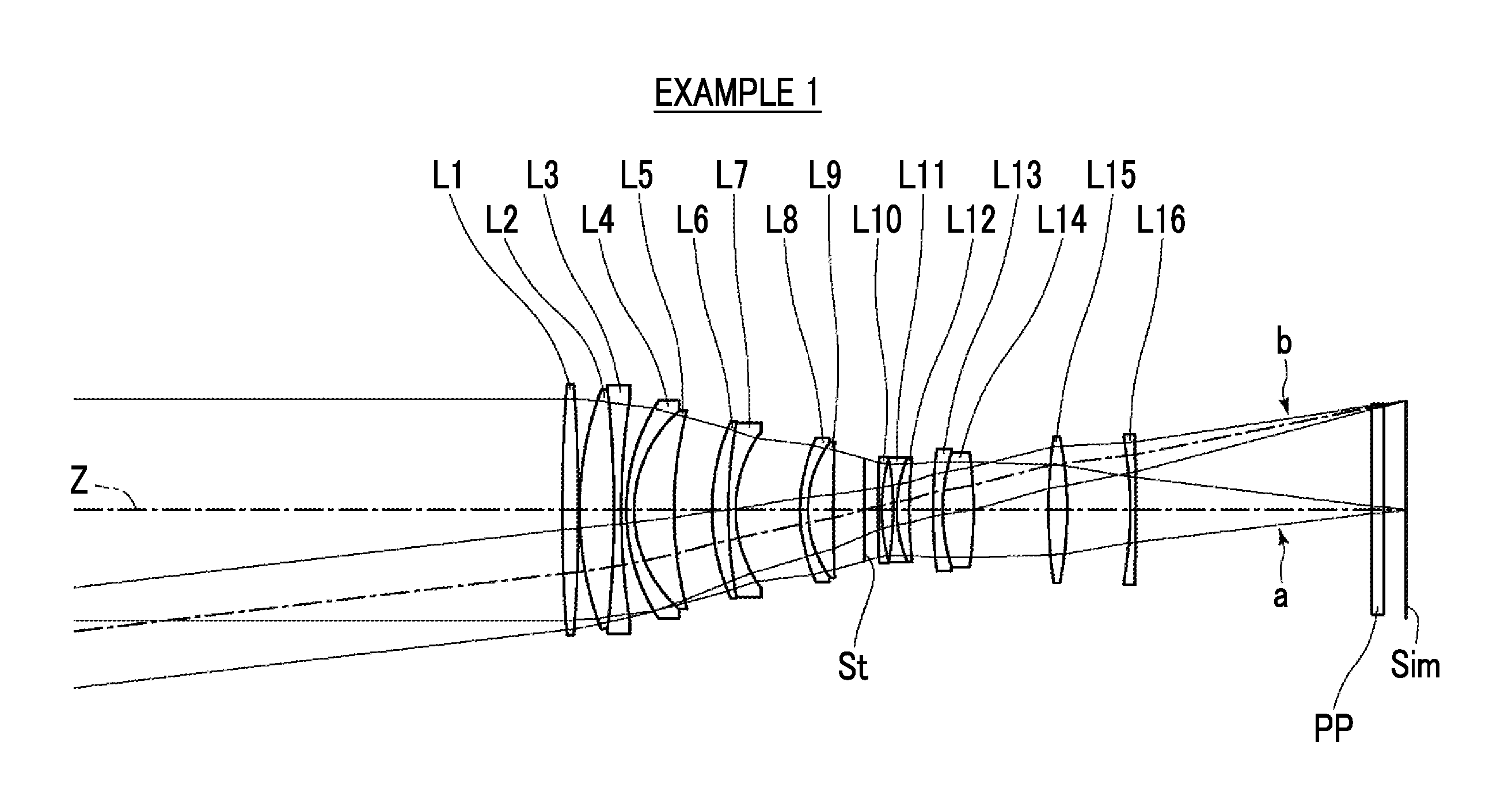
[0023] FIG. 1 is a cross-sectional view illustrating a lens configuration of an imaging lens (in common with that of Example 1) according to an embodiment of the present invention.
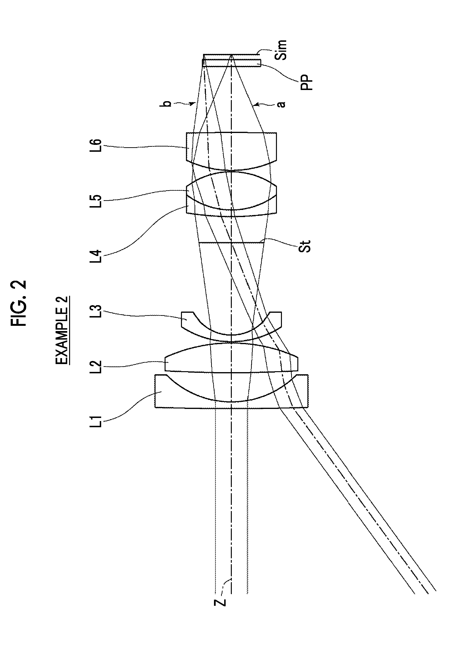
[0024] FIG. 2 is a cross-sectional view illustrating a lens configuration of an imaging lens of Example 2 of the present invention.
[0025] FIG. 3 is a cross-sectional view illustrating a lens configuration of an imaging lens of Example 3 of the present invention.
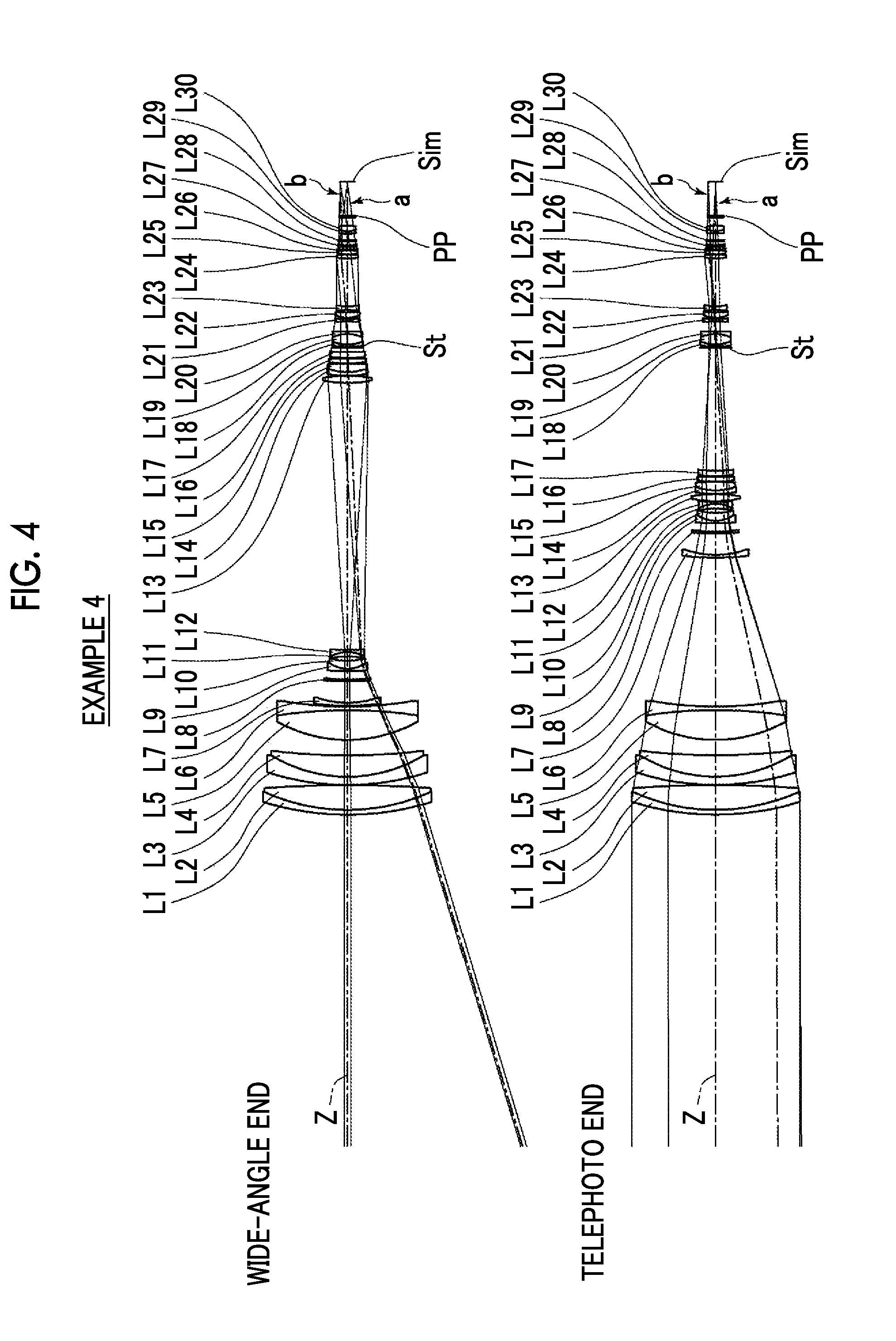
[0026] FIG. 4 is a cross-sectional view illustrating a lens configuration of an imaging lens of Example 4 of the present invention.
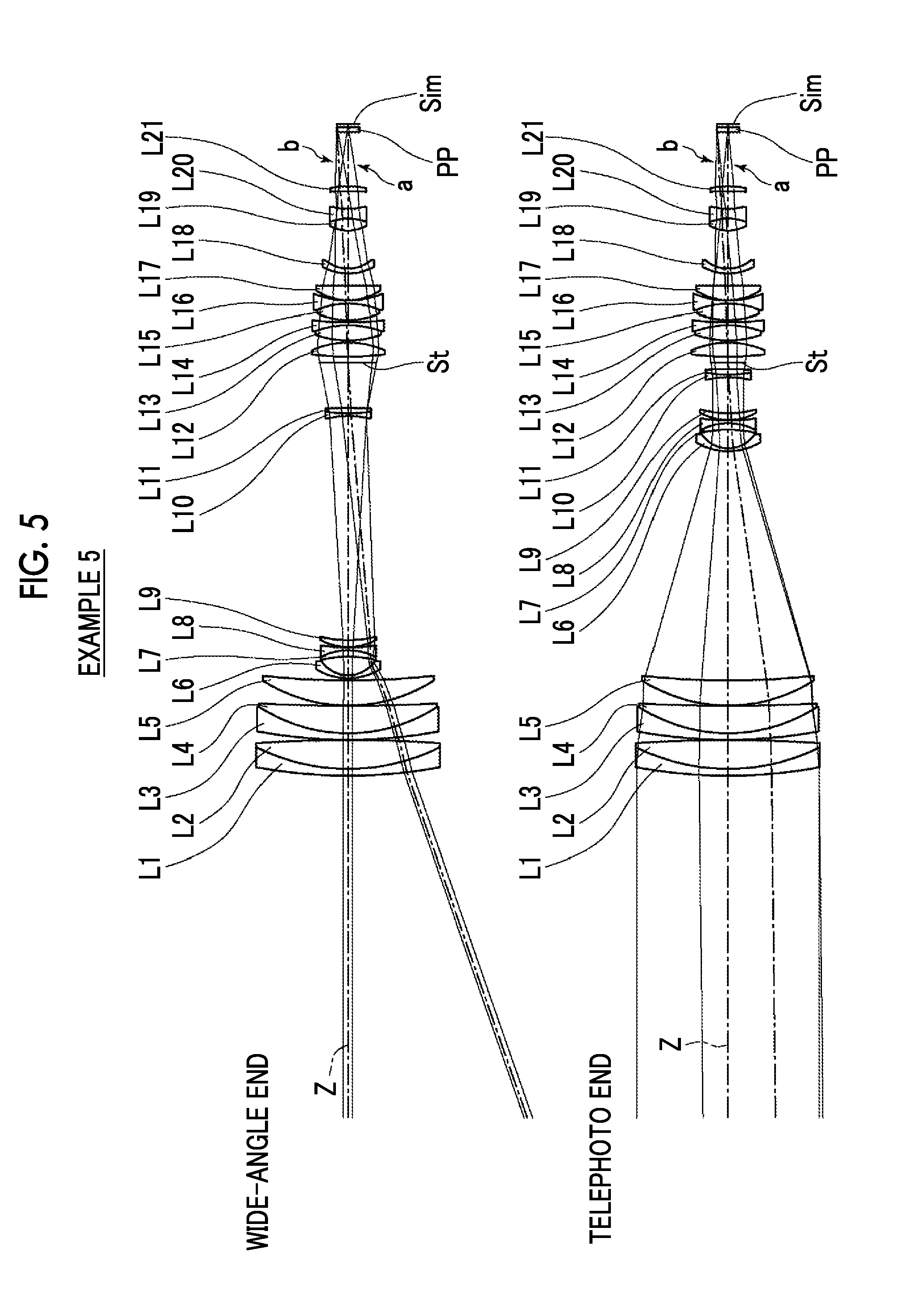
[0027] FIG. 5 is a cross-sectional view illustrating a lens configuration of an imaging lens of Example 5 of the present invention.
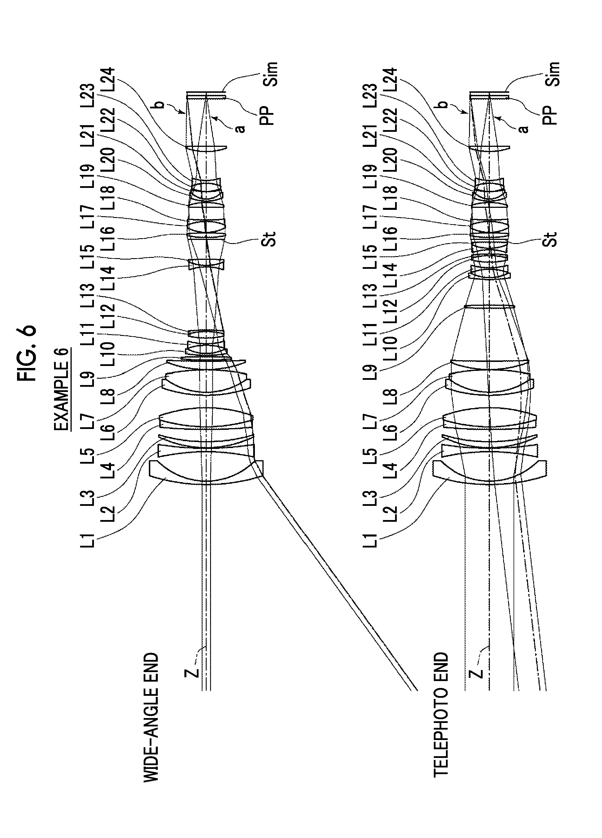
[0028] FIG. 6 is a cross-sectional view illustrating a lens configuration of an imaging lens of Example 6 of the present invention.
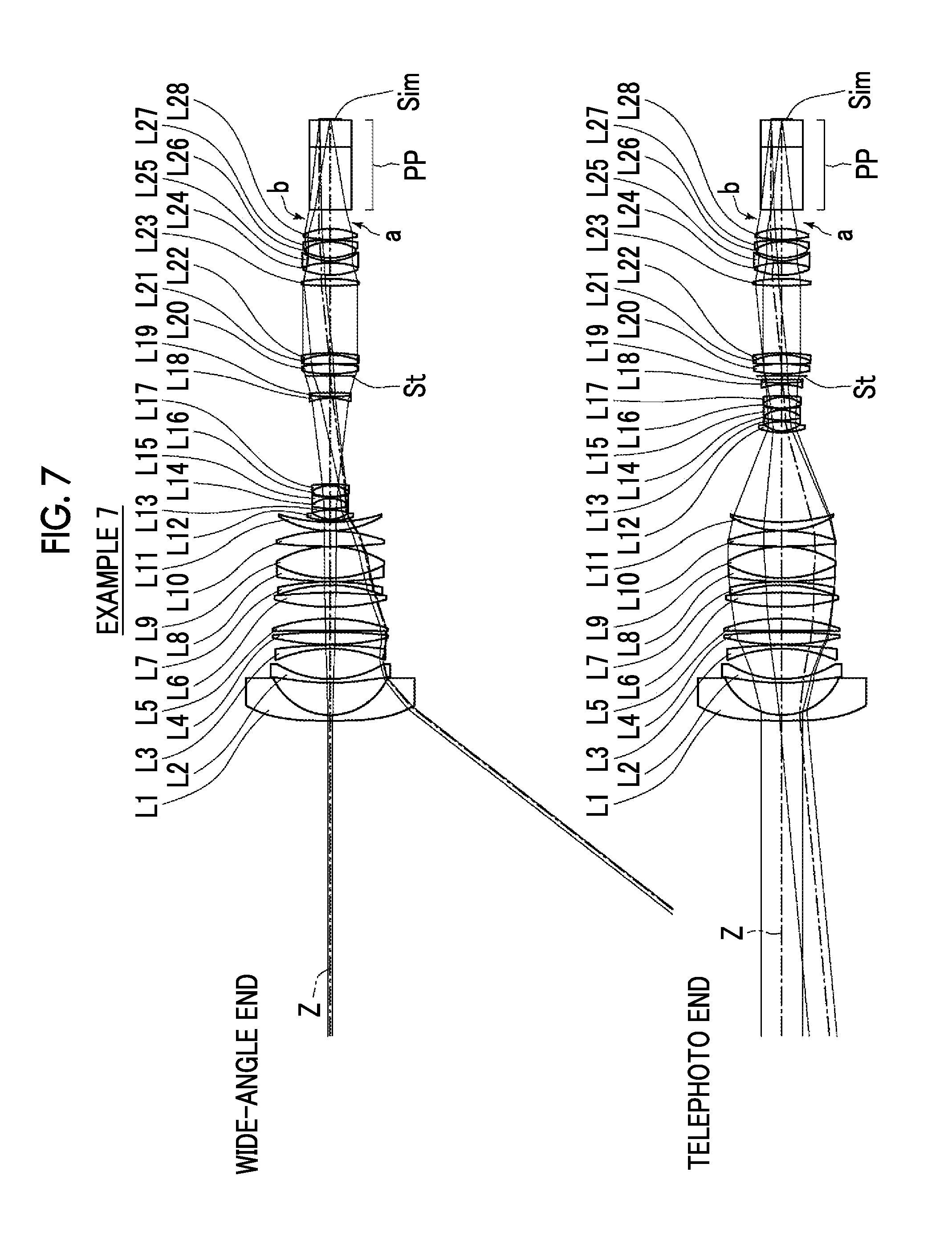
[0029] FIG. 7 is a cross-sectional view illustrating a lens configuration of an imaging lens of Example 7 of the present invention.
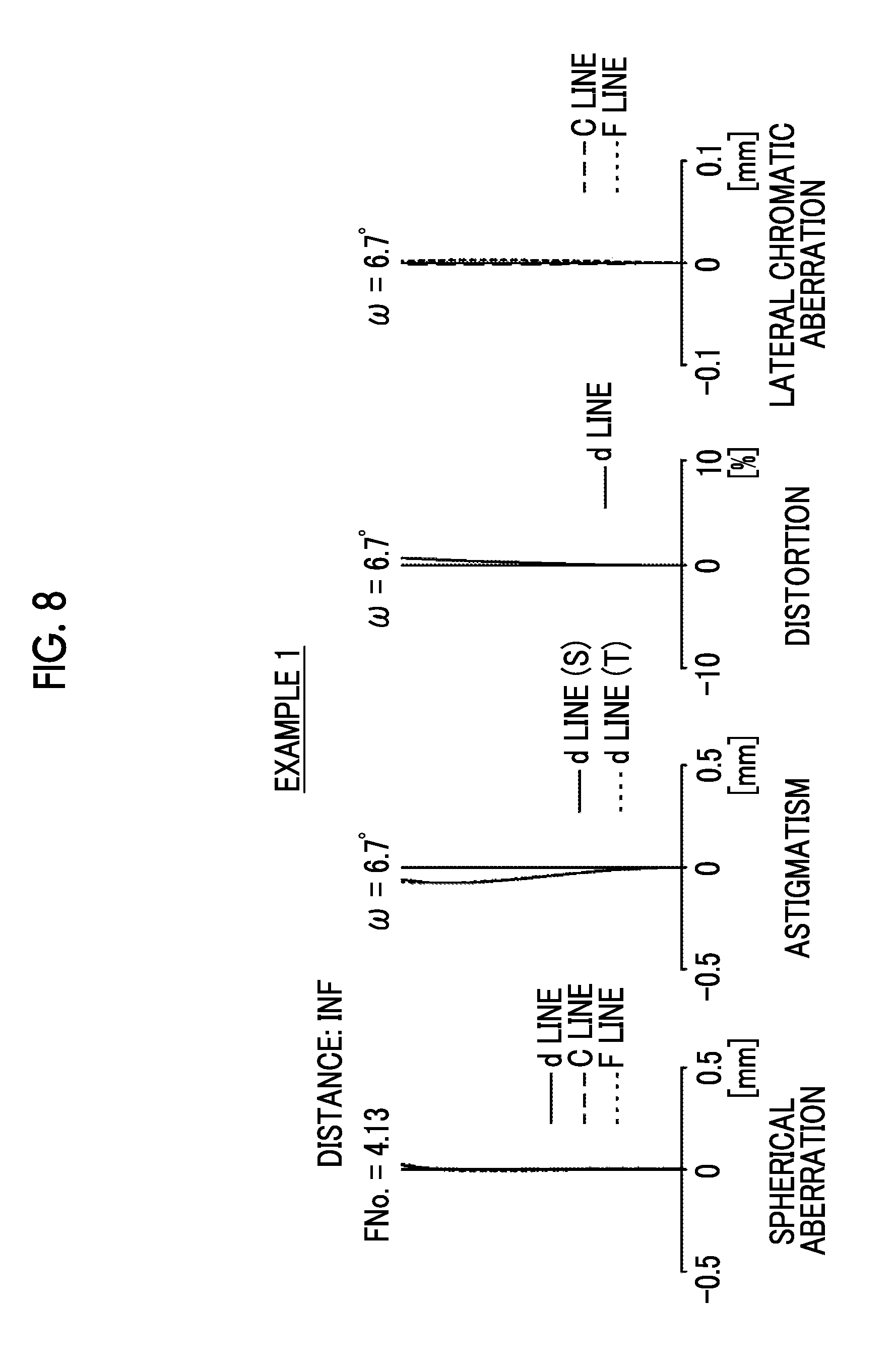
[0030] FIG. 8 is a diagram of aberrations of the imaging lens of Example 1 of the present invention.
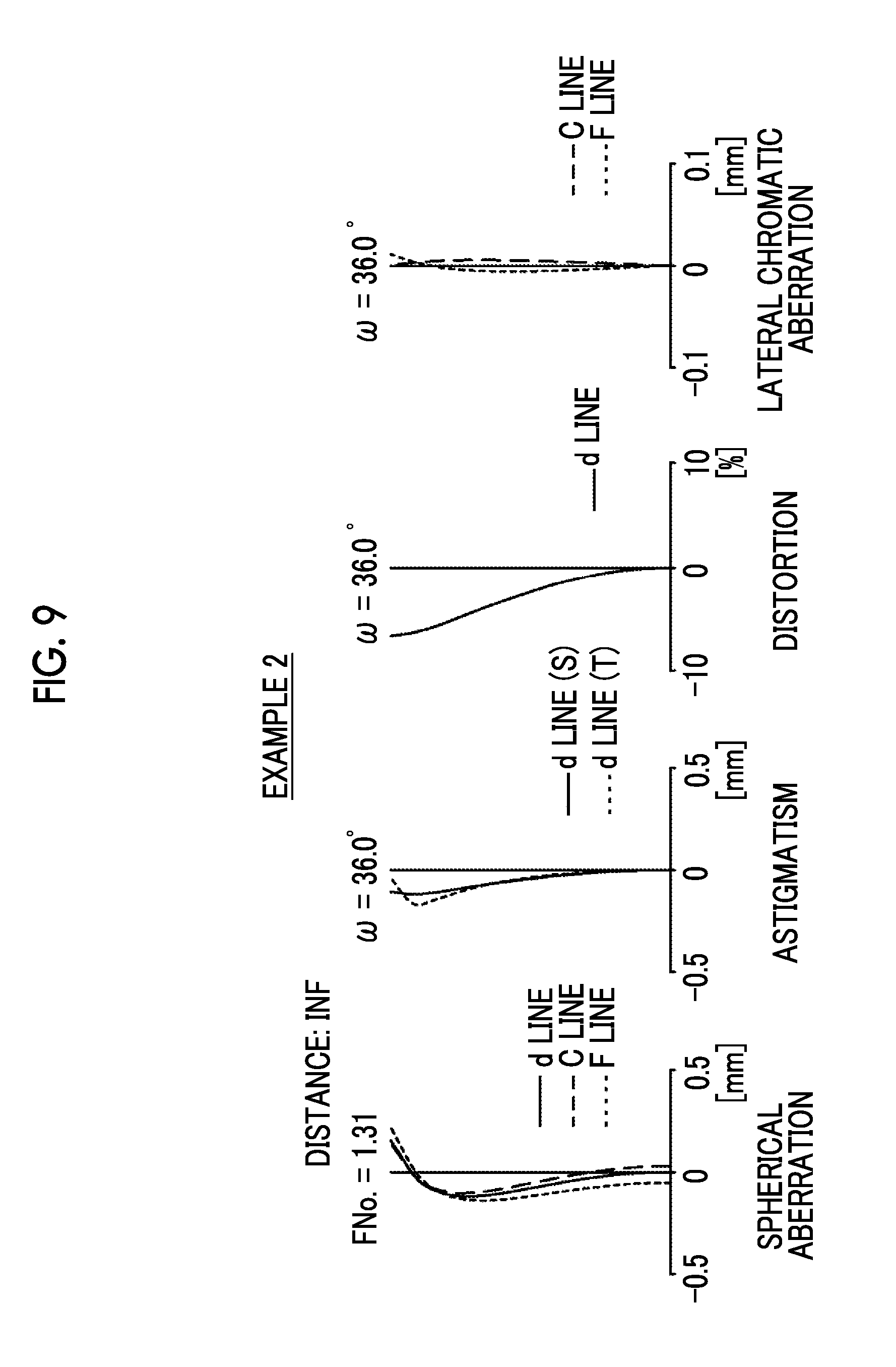
[0031] FIG. 9 is a diagram of aberrations of the imaging lens of Example 2 of the present invention.
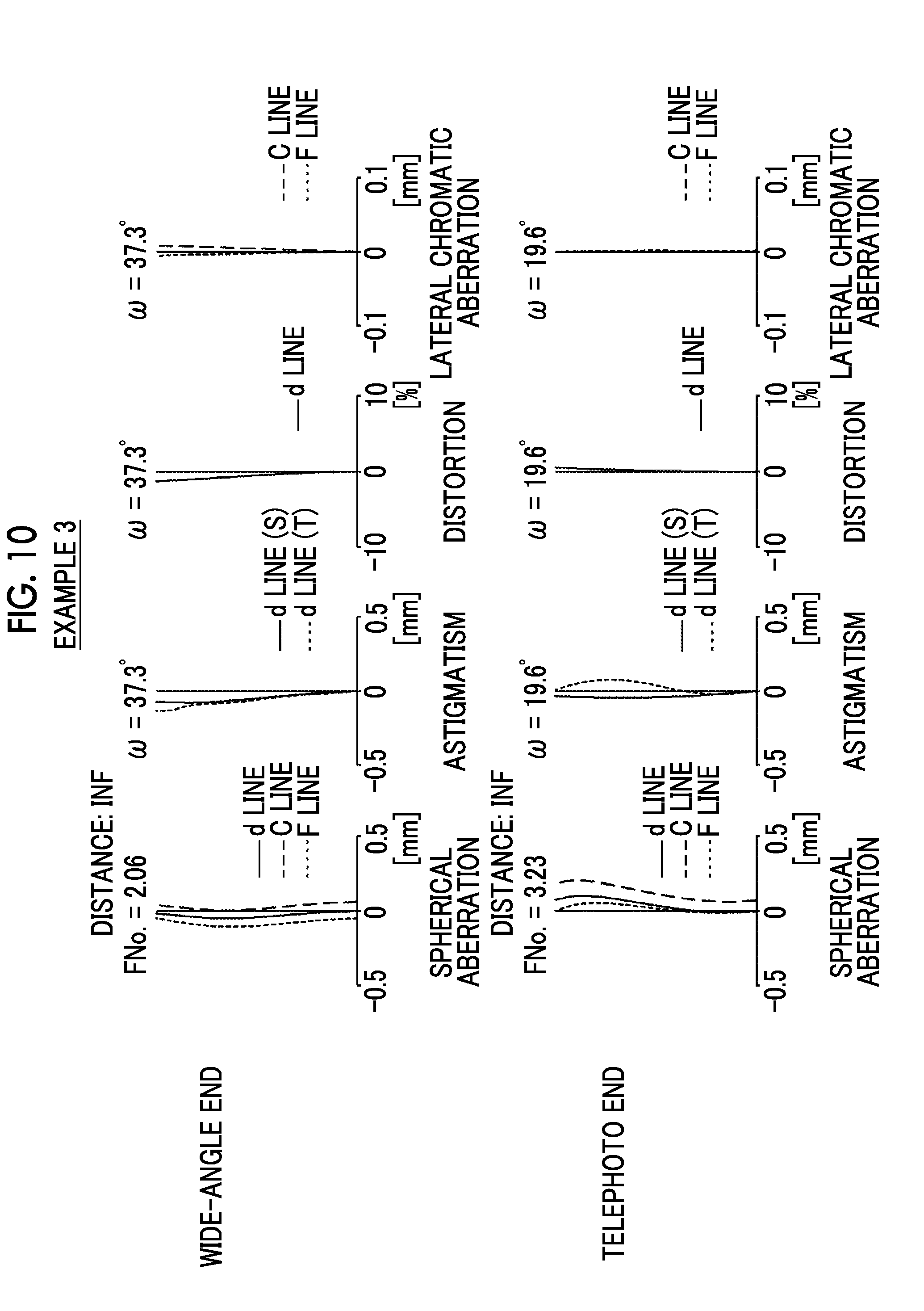
[0032] FIG. 10 is a diagram of aberrations of the imaging lens of Example 3 of the present invention.
[0033] FIG. 11 is a diagram of aberrations of the imaging lens of Example 4 of the present invention.
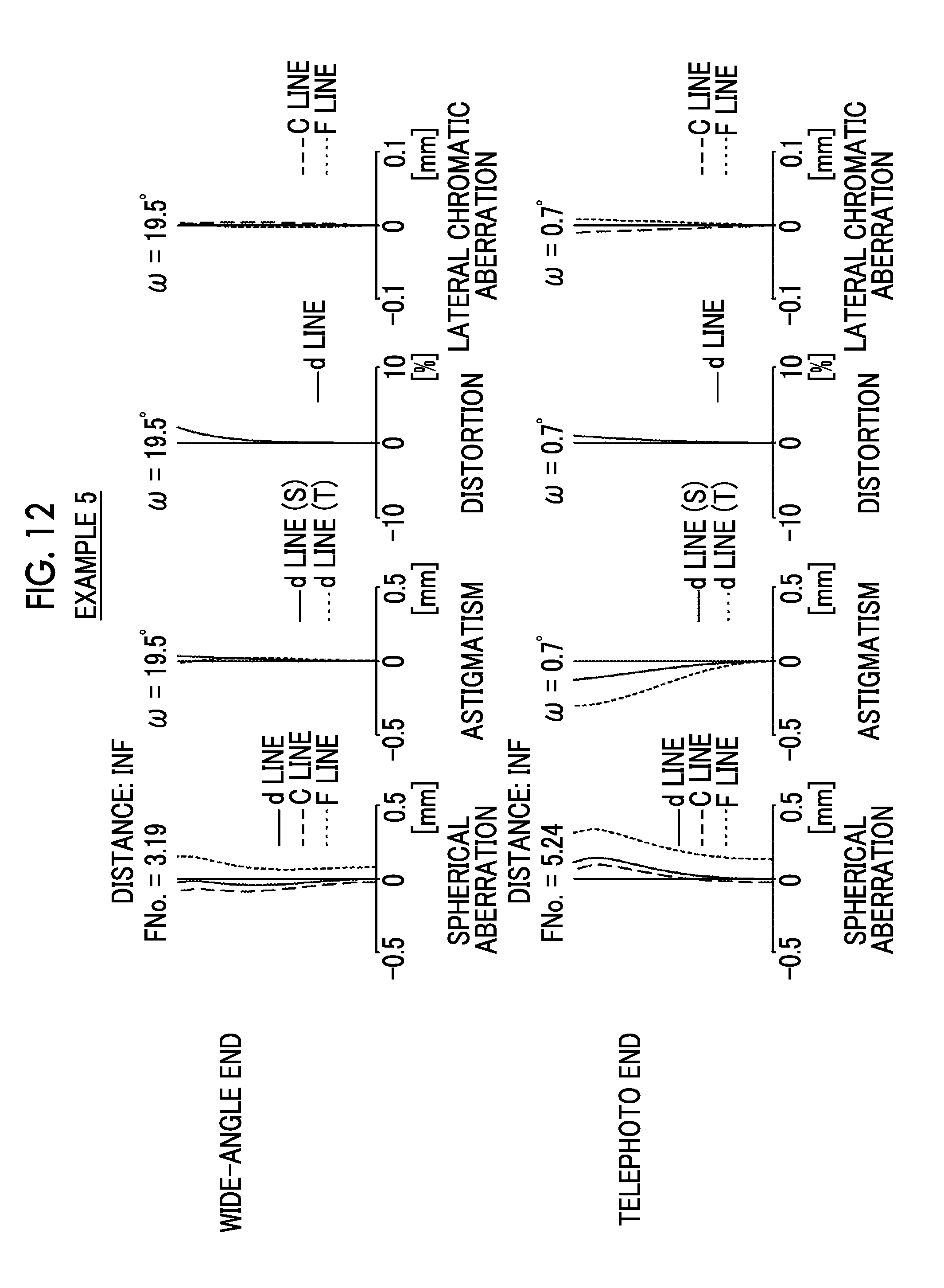
[0034] FIG. 12 is a diagram of aberrations of the imaging lens of Example 5 of the present invention.
[0035] FIG. 13 is a diagram of aberrations of the imaging lens of Example 6 of the present invention.
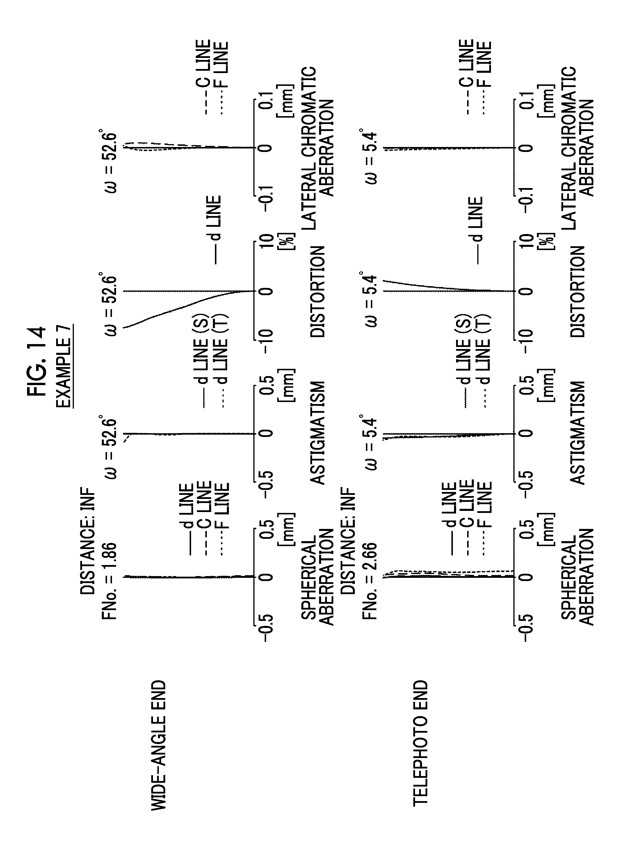
[0036] FIG. 14 is a diagram of aberrations of the imaging lens of Example 7 of the present invention.
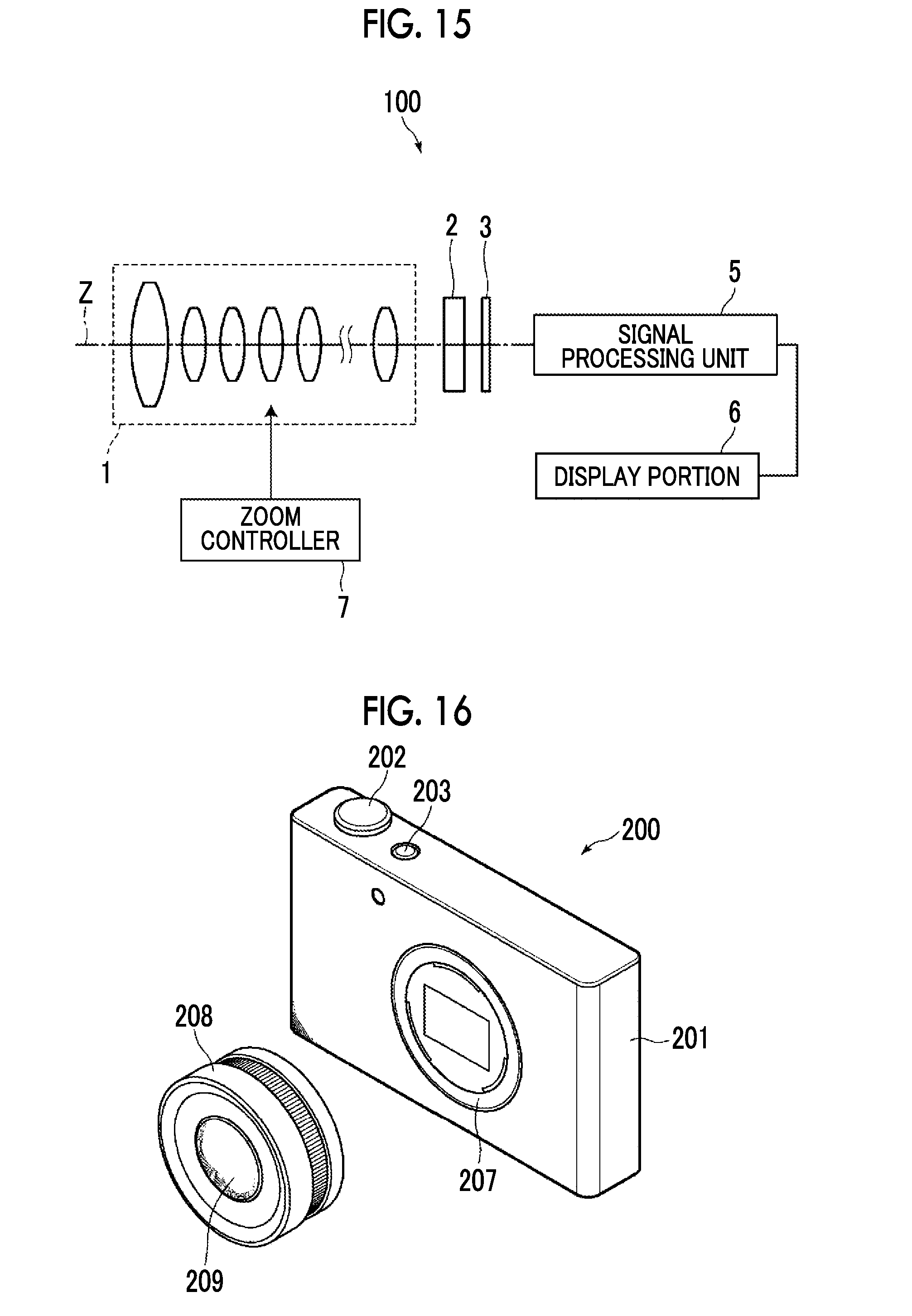
[0037] FIG. 15 is a schematic configuration diagram of an optical apparatus according to an embodiment of the present invention.
[0038] FIG. 16 is a perspective view illustrating a front side of an optical apparatus according to another embodiment of the present invention.
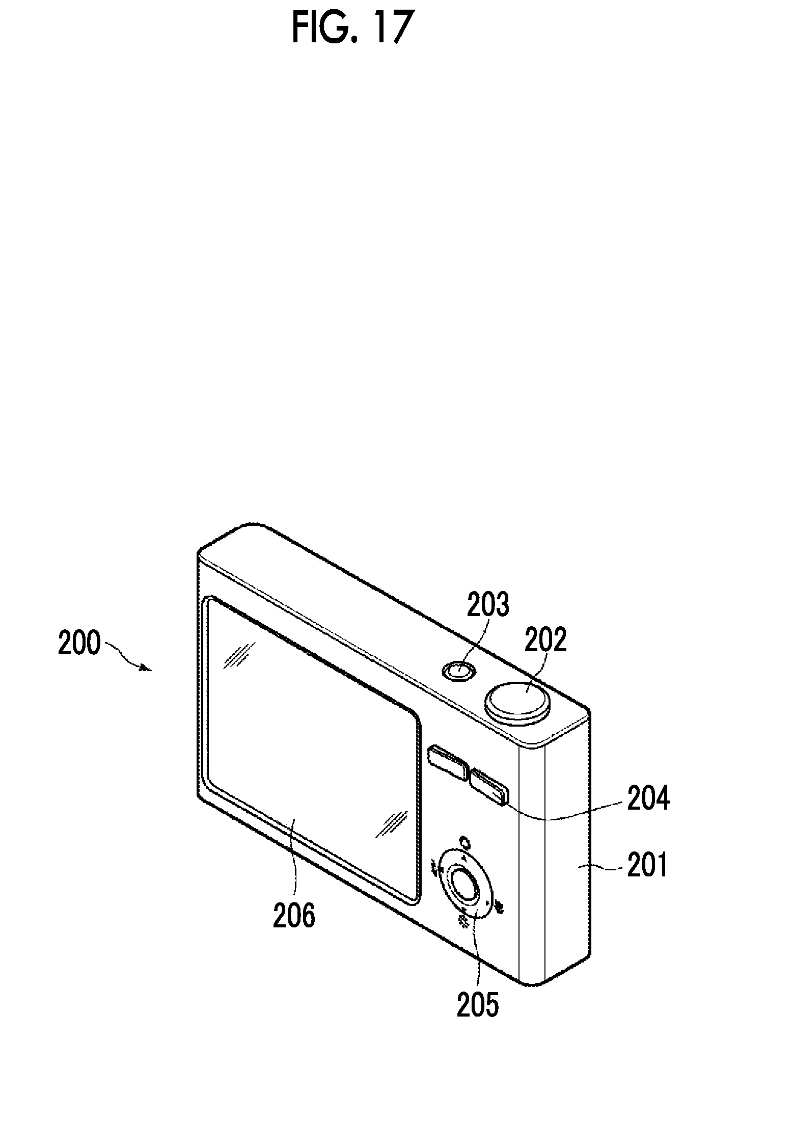
[0039] FIG. 17 is a perspective view illustrating a rear surface side of the optical apparatus of FIG. 16.
DESCRIPTION OF THE PREFERRED EMBODIMENTS
[0040] Hereinafter, an embodiment of the present invention will be described in detail with reference to the accompanying drawings. FIG. 1 is a cross-sectional view illustrating a lens configuration of an imaging lens according to an embodiment of the present invention. The configuration example shown in FIG. 1 is in common with the configuration of an imaging lens of Example 1 described later. In FIG. 1, the left side is an object side, the right side is an image side, and a shown aperture stop St shows its position on the optical axis Z without necessarily indicating its size or shape. In addition, FIG. 1 shows a state of being focused on the infinite object, and shows an on-axis light flux a and a light flux b of the maximum angle of view together.
[0041] Meanwhile, in a case where the imaging lens is mounted in an optical apparatus, it is preferable to include various types of filters and/or protective cover glass according to the specification of the optical apparatus. Thus, in FIG. 1, an example is shown in which a plane parallel plate-like optical member PP oriented to these components is disposed between a lens system and an image surface Sim. However, the position of the optical member PP is not limited to that shown in FIG. 1, and a configuration can also be used in which the optical member PP is omitted.
[0042] According to the present embodiment, there is provided an imaging lens in which a plurality of lenses are combined with each other, including at least one negative lens that satisfies the following Conditional Expressions (1) to (3) in a case where a refractive index at a d line of a negative lens included in the imaging lens is set to nN, an Abbe number at the d line of the negative lens is set to .nu.N, and a rate of change of the refractive index at the d line of the negative lens with respect to a change in temperature at 25.degree. C. is set to dnN/dt, wherein a positive lens having a largest Abbe number at the d line among positive lenses included in the imaging lens satisfies the following Conditional Expressions (4) and (5) in a case where an Abbe number at the d line of the positive lens having a largest Abbe number at the d line is set to .nu.P1, and a partial dispersion ratio of the positive lens having a largest Abbe number at the d line is set to .theta.P1gF.
1.65<nN<1.75 (1)
45<.nu.N<55 (2)
dnN/dt<0.times.10.sup.-6/.degree. C. (3)
63<.nu.P1 (4)
0.644<.theta.P1gF+0.001618.times..nu.P1 (5)
[0043] Conditional Expressions (1) to (3) are conditions for satisfactorily correcting defocusing with a change in temperature even in a case where a material having large abnormal dispersibility is used in a positive lens. The negative lens that satisfies Conditional Expressions (1) to (3) refers to a negative lens in which dispersion is relatively low and refractive index is high while having a negative rate of change of the refractive index, and can correct a direction in which a focus position during a rise in temperature is shortened. Since a lot of optical materials have a positive rate of change of the refractive index, the negative lens that satisfies Conditional Expressions (1) to (3) and a lens formed of other general optical materials are combined with each other, and thus it is possible to satisfactorily correct chromatic aberration and defocusing due to a change in temperature.
[0044] In addition, a positive lens having a largest Abbe number at the d line among positive lenses included in the imaging lens is made to satisfy Conditional Expressions (4) and (5), and thus it is possible to make a design in which chromatic aberration is suppressed. Further, it is possible to correct defocusing with a change in temperature while suppressing field curvature and chromatic aberration by combination with the negative lens that satisfies Conditional Expressions (1) to (3).
[0045] The value (nN) is not set to be equal to or less than the lower limit of Conditional Expression (1), and thus it is possible to prevent the refractive index from excessively decreasing, which leads to the advantage of the correction of field curvature. The value (nN) is not set to be equal to or greater than the upper limit of Conditional Expression (1), and thus it is possible to prevent the refractive index from excessively increasing, and to secure an Abbe number required for chromatic aberration correction. Meanwhile, in a case where Conditional Expression (1-1) is satisfied, it is possible to make characteristics more satisfactory.
1.69<nN<1.71 (1-1)
[0046] The value (.nu.N) is not set to be equal to or less than the lower limit of Conditional Expression (2), which leads to the advantage of the correction of lateral chromatic aberration and on-axis chromatic aberration. The value (.nu.N) is not set to be equal to or greater than the upper limit of Conditional Expression (2), which leads to the advantage of both the chromatic aberration correction and the refractive index. Meanwhile, in a case where Conditional Expression (2-1) is satisfied, it is possible to make characteristics more satisfactory.
50<.nu.N<52 (2-1)
[0047] The value (dnN/dt) is not set to be equal to or less than the lower limit of Conditional Expression (3), and thus it is possible to prevent a change in refractive index with respect to a change in temperature from excessively increasing, and to prevent the correction of defocusing from being in excess. The value (dnN/dt) is not set to be equal to or greater than the upper limit of Conditional Expression (3), and thus it is possible to prevent a change in refractive index with respect to a change in temperature from excessively decreasing, and to prevent the correction of defocusing from being in deficiency. Meanwhile, in a case where Conditional Expression (3-1) is satisfied, it is possible to make characteristics more satisfactory.
-2.times.10.sup.-6/.degree. C.<dnN/dt<-1.times.10.sup.-6/.degree. C. (3-1)
[0048] The value (.nu.P1) is not set to be equal to or less than the lower limit of Conditional Expression (4), which leads to the advantage of the correction of lateral chromatic aberration. The value (.nu.P1) is not set to be equal to or greater than the upper limit of Conditional Expression (4), and thus it is possible to prevent the refractive index from excessively decreasing, which leads to the advantage of the correction of spherical aberration. Meanwhile, in a case where Conditional Expression (4-1) is satisfied, it is possible to make characteristics more satisfactory.
75<.nu.P1<100 (4-1)
[0049] The value (.theta.P1gF+0.001618.times..nu.P1) is not set to be equal to or less than the lower limit of Conditional Expression (5), and thus it is possible to prevent abnormal dispersibility from excessively decreasing, which leads to the facilitation of the correction of a secondary spectrum. The value (.theta.P1gF+0.001618.times..nu.P1) is not set to be equal to or greater than the upper limit of Conditional Expression (5), and thus it is possible to prevent the refractive index from excessively decreasing, which leads to the advantage of the correction of spherical aberration. Meanwhile, in a case where Conditional Expression (5-1) is satisfied, it is possible to make characteristics more satisfactory.
0.665<.theta.P1gF+0.001618.times..nu.P1<0.7 (5-1)
[0050] In the imaging lens of the present embodiment, it is preferable that at least one negative lens among negative lenses that satisfy Conditional Expressions (1) to (3) satisfies the following Conditional Expression (6) in a case where a focal length of the negative lens is set to fN, and a focal length of the whole system during focusing on an infinite object is set to f. The value (|fN|/f) is not set to be equal to or greater than the upper limit of Conditional Expression (6), and thus it is possible to prevent the refractive power of the negative lens that satisfies Conditional Expressions (1) to (3) from becoming excessively weak, and to prevent a temperature correction effect from excessively decreasing. Meanwhile, in a case where Conditional Expression (6-1) is satisfied, it is possible to make characteristics more satisfactory. The value (|fN|/f) is not set to be equal to or less than the lower limit of Conditional Expression (6), and thus it is possible to prevent the refractive power of the negative lens that satisfies Conditional Expressions (1) to (3) from becoming excessively strong, and to prevent the temperature correction effect from excessively increasing.
|fN|/f<10 (6)
0.5<|fN|/f<5 (6-1)
[0051] In addition, it is preferable to include at least one positive lens that satisfies the following Conditional Expressions (7) to (9) in a case where a refractive index at the d line of a positive lens included in the imaging lens is set to nP2, an Abbe number at the d line of the positive lens is set to .nu.P2, and a rate of change of the refractive index at the d line of the positive lens with respect to a change in temperature at 25.degree. C. is set to dnP2/dt.
1.6<nP2<1.85 (7)
40<.nu.P2<60 (8)
6.times.10.sup.-6/.degree. C.<dnP2/dt (9)
[0052] Conditional Expressions (7) to (9) are conditions for enabling a lens system to suppress chromatic aberration and spherical aberration while correcting a change in focus with respect to a change in temperature. It is possible to correct a direction in which a focus position during a rise in temperature is shortened by disposing the positive lens that satisfies Conditional Expressions (7) to (9), that is, a lens formed of a material having a large value with a positive change in refractive index with respect to a change in temperature.
[0053] The value (nP2) is not set to be equal to or less than the lower limit of Conditional Expression (7), and thus it is possible to prevent the refractive index from excessively decreasing, which leads to the advantage of the correction of spherical aberration. The value (nP2) is not set to be equal to or greater than the upper limit of Conditional Expression (7), and thus it is possible to prevent the refractive index from excessively increasing, and to secure an Abbe number required for chromatic aberration correction. Meanwhile, in a case where Conditional Expression (7-1) is satisfied, it is possible to make characteristics more satisfactory.
1.65<nP2<1.8 (7-1)
[0054] The value (.nu.P2) is not set to be equal to or less than the lower limit of Conditional Expression (8), which leads to the advantage of the correction of lateral chromatic aberration and on-axis chromatic aberration. The value (.nu.P2) is not set to be equal to or greater than the upper limit of Conditional Expression (8), which leads to the advantage of both the chromatic aberration correction and the refractive index. Meanwhile, in a case where Conditional Expression (8-1) is satisfied, it is possible to make characteristics more satisfactory.
42<.nu.P2<57 (8-1)
[0055] The value (dnP2/dt) is not set to be equal to or less than the lower limit of Conditional Expression (9), and thus it is possible to prevent a change in refractive index with respect to a change in temperature from excessively decreasing, and to prevent the correction of defocusing from being in deficiency. The value (dnP2/dt) is not set to be equal to or greater than the upper limit of Conditional Expression (9), and thus it is possible to prevent a change in refractive index with respect to a change in temperature from excessively increasing, and to prevent the correction of defocusing from being in excess. Meanwhile, in a case where Conditional Expression (9-1) is satisfied, it is possible to make characteristics more satisfactory.
6.5.times.10.sup.-6/.degree. C.<dnP2/dt<11.times.10.sup.-6/.degree. C. (9-1)
[0056] In addition, it is preferable that the positive lens that satisfies Conditional Expressions (7) to (9) satisfies the following Conditional Expression (10), in a case where a focal length of the positive lens is set to fP2, and a focal length of the whole system during focusing on an infinite object is set to f. The value (fP2/f) is not set to be equal to or less than the lower limit of Conditional Expression (10), and thus it is possible to prevent the refractive power of the positive lens from becoming excessively strong, and to prevent the temperature correction effect from excessively increasing. The value (fP2/f) is not set to be equal to or greater than the upper limit of Conditional Expression (10), and thus it is possible to prevent the refractive power of the positive lens from becoming excessively weak, and to prevent the temperature correction effect from excessively decreasing. Meanwhile, in a case where Conditional Expression (10-1) is satisfied, it is possible to make characteristics more satisfactory.
fP2/f<15 (10)
0.2<fP2/f<5 (10-1)
[0057] In addition, the imaging lens may be a single-focus lens. In that case, it is preferable to satisfy the following Conditional Expression (11), and more preferable to satisfy the following Conditional Expression (11-1) in a case where a height of a paraxial on-axis light ray on an object-side surface of the negative lens that satisfies Conditional Expressions (1) to (3) is set to HN, and a maximum value of heights of a paraxial on-axis light ray on each lens surface of all lenses included in the imaging lens is set to Hmax. The value (|HN/Hmax|) is not set to be equal to or less than the lower limit of Conditional Expression (11), and thus it is possible to prevent the height of a paraxial on-axis light ray of the negative lens that satisfies Conditional Expressions (1) to (3) from becoming excessively small, and to prevent a correction effect with respect to a change in temperature from becoming excessively weak. Meanwhile, in a case where Conditional Expression (11-1) is satisfied, it is possible to make characteristics more satisfactory.
0.39-|HN/H max| (11)
0.49-|HN/H max|<1 (11-1)
[0058] In addition, the imaging lens may have a zooming function. In that case, in a case where defocusing with a change in temperature is corrected throughout the entire zooming region, it is preferable to satisfy the following Conditional Expression (12) in a case where a height of a paraxial on-axis light ray at a telephoto end on an object-side surface of the negative lens that satisfies Conditional Expressions (1) to (3) is set to HNt, a height of a paraxial on-axis light ray at the telephoto end of a surface having a maximum height of a paraxial on-axis light ray at a wide-angle end on each lens surface of all lenses included in the imaging lens is set to Htwm, a height of a paraxial on-axis light ray at the wide-angle end on the object-side surface of the negative lens that satisfies Conditional Expressions (1) to (3) is set to HNw, and a maximum value of heights of a paraxial on-axis light ray at the wide-angle end on each lens surface of all lenses included in the imaging lens is set to Hwwm. The value (|(HNt/Htwm)/(HNw/Hwwm)|) is not set to be equal to or less than the lower limit of Conditional Expression (12), and thus it is possible to prevent the height of an on-axis light ray at the telephoto end from becoming excessively small, and to secure a correction effect on the telephoto end side. The value (|(HNt/Htwm)/(HNw/Hwwm)|) is not set to be equal to or greater than the upper limit of Conditional Expression (12), and thus it is possible to prevent the height of an on-axis light ray at the wide-angle end from becoming excessively small, and to secure a correction effect on the wide-angle end side. Meanwhile, in a case where Conditional Expression (12-1) is satisfied, it is possible to make characteristics more satisfactory.
|(HNt/Htwm)/(HNw/Hwwm)|<1.8 (12)
0.4<|(HNt/Htwm)/(HNw/Hwwm)|<1.5 (12-1)
[0059] In addition, the imaging lens may have a zooming function. In that case, particularly, in a case where defocusing with a change in temperature at the telephoto end is corrected, it is preferable to satisfy the following Conditional Expression (13) in a case where a height of a paraxial on-axis light ray at a telephoto end on an object-side surface of the negative lens that satisfies Conditional Expressions (1) to (3) is set to HNt, a height of a paraxial on-axis light ray at the telephoto end of a surface having a maximum height of a paraxial on-axis light ray at a wide-angle end on each lens surface of all lenses included in the imaging lens is set to Htwm, a height of a paraxial on-axis light ray at the wide-angle end on the object-side surface of the negative lens that satisfies Conditional Expressions (1) to (3) is set to HNw, and a maximum value of heights of a paraxial on-axis light ray at the wide-angle end on each lens surface of all lenses included in the imaging lens is set to Hwwm. The value (|(HNt/Htwm)/(HNw/Hwwm)|) is not set to be equal to or less than the lower limit of Conditional Expression (13), and thus it is possible to prevent a difference between the heights of on-axis light rays at the wide-angle end and the telephoto end from excessively decreasing, and to prevent the correction of defocusing with a change in temperature at the telephoto end from being insufficient. Meanwhile, in a case where Conditional Expression (13-1) is satisfied, it is possible to make characteristics more satisfactory. The value (|(HNt/Htwm)/(HNw/Hwwm)|) is not set to be equal to or greater than the upper limit of Conditional Expression (13), and thus it is possible to prevent the difference between the heights of on-axis light rays at the wide-angle end and the telephoto end from excessively increasing, and to prevent the correction of defocusing with a change in temperature at the telephoto end from being in excess.
1.8<|(HNt/Htwm)/(HNw/Hwwm)| (13)
2<|(HNt/Htwm)/(HNw/Hwwm)|<50 (13-1)
[0060] In addition, in the example shown in FIG. 1, an example is shown in which the optical member PP is disposed between the lens system and the image surface Sim, but instead of disposing various types of filters, such as a low-pass filter or a filter in which a specific wavelength region is cut, between the lens system and the image surface Sim, various types of filters described above may be disposed between respective lenses, or coating having the same actions as those of various types of filters may be performed on the lens surface of any of the lenses.
[0061] Next, numerical value examples of the imaging lens of the present invention will be described. First, an imaging lens of Example 1 will be described. FIG. 1 shows a cross-sectional view illustrating a lens configuration of the imaging lens of Example 1. In FIG. 1 and FIGS. 2 to 7 corresponding to Examples 2 to 7 described later, the left side is an object side, the right side is an image side, and a shown aperture stop St shows its position on the optical axis Z without necessarily indicating its size or shape. In addition, FIGS. 1 to 7 show a state of being focused on the infinite object, and show an on-axis light flux a and a light flux b of the maximum angle of view together.
[0062] The imaging lens of Example 1 is a single-focus lens, and is composed of sixteen lenses, that is, lenses L1 to L16 in order from the object side. In the imaging lens of Example 1, the lens L16 (its material is S-LAL20 manufactured by OHARA INC.) is a negative lens that satisfies Conditional Expressions (1) to (3), the lens L14 (its material is S-LAL54Q manufactured by OHARA INC.) is a positive lens that satisfies Conditional Expressions (7) to (9), and the lens L9 is a positive lens having a largest Abbe number at the d line among positive lenses included in the imaging lens.
[0063] Table 1 shows basic lens data of the imaging lens of Example 1, and Table 2 shows data relating to specifications. In the following, the meanings of symbols in the tables will be described by taking an example of those in Example 1, but the same is basically true of Examples 2 to 7.
[0064] In the lens data of Table 1, the column of a surface number shows surface numbers sequentially increasing toward the image surface side with the surface of an element closest to the object side regarded as a first surface and, the column of a curvature radius shows curvature radii of respective surfaces, and the column of a surface distance shows distances on the optical axis Z between the respective surfaces and the next surfaces. In addition, the column of n shows refractive indexes of respective optical elements at the d line (a wavelength of 587.6 nm (nanometer)), the column of .nu. shows Abbe numbers of the respective optical elements at the d line (a wavelength of 587.6 nm (nanometer)), the column of dn/dt shows rates of change in refractive index at the d line (a wavelength of 587.6 nm (nanometer)) with respect to a change in temperature at 25.degree. C. of the respective optical elements, the column of .theta.gF shows partial dispersion ratios of the respective optical elements, and the column of Conditional Expression (5) shows values of Conditional Expression (5) of the respective optical elements. Meanwhile, in Table 1, ".times.10.sup.-6/.degree. C." is omitted with respect to the values of dn/dt.
[0065] In addition, the sign of the curvature radius is set to be positive in a case where a surface shape is convex on the object side, and is set to be negative in a case where a surface shape is convex on the image surface side. Basic lens data indicates the aperture stop St and optical member PP together. In the place of a surface number of a surface equivalent to the aperture stop St, a term of (stop) is written together with the surface number.
[0066] The data relating to specifications of Table 2 shows values of a focal length f, a back focus Bf, an F-Number FNo., and the total angle of view 2.omega.[.degree. ].
[0067] For the basic lens data and the data relating to specifications, a degree (.degree.) is used as the unit of an angle, and mm (millimeter) is used as the unit of a length, but it is also possible to use other appropriate units since an optical system can be used even in a case where the optical system is magnified or reduced in proportion.
TABLE-US-00001 TABLE 1 EXAMPLE 1.cndot.LENS DATA (n AND v ARE BASED ON d LINE) SURFACE CURVATURE SURFACE EXPRESSION NUMBER RADIUS DISTANCE n .nu. .theta.gF dn/dt (5) 1 436.2065 4.3542 1.48749 70.24 0.53007 -0.8 0.64372 2 -436.2065 0.2438 3 90.3149 9.1985 1.49700 81.54 0.53748 -6.1 0.66941 4 -303.0390 1.9496 1.65160 58.62 0.54102 3.1 0.63587 5 192.7307 1.3619 6 53.2590 2.0706 1.51742 52.43 0.55649 2.4 0.64132 7 35.0424 10.6348 1.49700 81.54 0.53748 -6.1 0.66941 8 103.2588 10.1387 9 58.2805 4.3382 1.90366 31.31 0.59481 3.6 0.64547 10 125.5233 1.9418 1.80610 40.93 0.57019 7 0.63641 11 35.6304 16.9295 12 42.8907 2.2673 1.56732 42.82 0.57309 2.9 0.64237 13 30.2253 6.8840 1.43875 94.66 0.53402 -6.2 0.68718 14 438.6286 8.2402 15(STOP) .infin. 3.6368 16 357.1219 1.0199 1.85150 40.78 0.56958 5.4 0.63556 17 50.0030 3.1226 18 -78.3563 0.9580 1.72916 54.09 0.54490 4.9 0.63242 19 35.9157 3.2645 1.84666 23.78 0.62054 1.4 0.65902 20 118.8928 6.3200 21 122.1512 2.6266 1.89286 20.36 0.63944 1.1 0.67238 22 50.0834 8.2404 1.65100 56.24 0.54210 6.6 0.63310 23 -108.8489 19.9574 24 135.4182 5.0025 1.62588 35.70 0.58935 2.7 0.64711 25 -95.7474 16.7689 26 -108.9483 1.4930 1.69930 51.11 0.55523 -1.2 0.63793 27 -787.3933 62.9700 28 .infin. 3.2000 1.51680 64.20 0.53430 29 .infin. 5.8797
TABLE-US-00002 TABLE 2 EXAMPLE 1.cndot.SPECIFICATION (d LINE) f 242.52 Bf 70.96 FNo. 4.12 2.omega.[.degree.] 13.4
[0068] FIG. 8 shows a diagram of aberrations of the imaging lens of Example 1. Meanwhile, spherical aberration, astigmatism, distortion, and lateral chromatic aberration are shown in order from the left side in FIG. 8. The diagram of aberrations indicating spherical aberration, astigmatism, and distortion shows aberrations in which the d line (a wavelength of 587.6 nm (nanometer)) is used as a reference wavelength. In the spherical aberration diagram, aberrations relating to the d line (a wavelength of 587.6 nm (nanometer)), a C line (a wavelength of 656.3 nm (nanometer)), and an F line (a wavelength of 486.1 nm (nanometer)) are shown by a solid line, a long dashed line, and a short dashed line. In the astigmatism diagram, aberrations in a sagittal direction and a tangential direction are shown by a solid line and a short dashed line, respectively. In the lateral chromatic aberration diagram, aberrations relating to the C line (a wavelength of 656.3 nm (nanometer)) and the F line (a wavelength of 486.1 nm (nanometer)) are shown by a long dashed line and a short dashed line, respectively. Meanwhile, FNo. in the spherical aberration diagram means an F-Number, and w in the other aberration diagrams means a half angle of view.
[0069] Next, an imaging lens of Example 2 will be described. FIG. 2 shows a cross-sectional view illustrating a lens configuration of the imaging lens of Example 2. The imaging lens of Example 2 is a single-focus lens, and is composed of six lenses, that is, lenses L1 to L6 in order from the object side. In the imaging lens of Example 2, the lens L1 (its material is S-LAL20 manufactured by OHARA INC.) is a negative lens that satisfies Conditional Expressions (1) to (3), the lens L6 (its material is S-LAH52Q manufactured by OHARA INC.) is a positive lens that satisfies Conditional Expressions (7) to (9), and the lens L5 is a positive lens having a largest Abbe number at the d line among positive lenses included in the imaging lens. In addition, Table 3 shows basic lens data of the imaging lens of Example 2, Table 4 shows data relating to specifications, and FIG. 9 shows a diagram of aberrations.
TABLE-US-00003 TABLE 3 EXAMPLE 2.cndot.LENS DATA (n AND .nu. ARE BASED ON d LINE) SURFACE CURVATURE SURFACE EXPRESSION NUMBER RADIUS DISTANCE n .nu. .theta.gF dn/dt (5) 1 373.3289 0.9998 1.69930 51.11 0.55523 -1.2 0.63793 2 13.7465 4.4135 3 173.0372 4.4821 1.84666 23.78 0.62054 1.4 0.65902 4 -23.8724 0.1998 5 13.6968 0.9998 1.48749 70.24 0.53007 -0.7 0.64372 6 6.5504 13.9171 7(STOP) .infin. 3.9257 8 40.6043 0.9998 1.84666 23.78 0.62054 1.4 0.65902 9 11.0954 5.7718 1.49700 81.54 0.53748 -6.1 0.66941 10 -11.2802 0.1998 11 15.6608 5.7220 1.79952 42.24 0.56758 10.2 0.63592 12 -251.4968 10.0000 13 .infin. 1.0000 1.51680 64.20 0.53430 14 .infin. 0.7616
TABLE-US-00004 TABLE 4 EXAMPLE 2.cndot.SPECIFICATION (d LINE) f 6.20 Bf 11.42 FNo. 1.30 2.omega.[.degree.] 72.0
[0070] Next, an imaging lens of Example 3 will be described. FIG. 3 shows a cross-sectional view illustrating a lens configuration of the imaging lens of Example 3. The imaging lens of Example 3 has a zooming function, and is composed of fourteen lenses, that is, lenses L1 to L14 in order from the object side. In the imaging lens of Example 3, the lens L2 (its material is S-LAL20 manufactured by OHARA INC.) is a negative lens that satisfies Conditional Expressions (1) to (3), the lens L5 (its material is S-LAH52Q manufactured by OHARA INC.) and the lens L7 (its material is S-LAL54Q manufactured by OHARA INC.) are positive lenses that satisfy Conditional Expressions (7) to (9), and the lens L3 is a positive lens having a largest Abbe number at the d line among positive lenses included in the imaging lens. In addition, Table 5 shows basic lens data of the imaging lens of Example 3, Table 6 shows data relating to specifications, Table 7 shows data relating to changing surface distances, Table 8 shows data relating to aspherical coefficients, and FIG. 10 shows a diagram of aberrations.
[0071] The data relating to specifications of Table 6 shows values of a zoom magnification, a focal length f, a back focus Bf, an F-Number FNo., and the total angle of view 2.omega.[.degree. ] with respect to each of the wide-angle end and the telephoto end.
[0072] In the lens data of Table 5, DD [surface number] is written in the places of surface distances having a change in distance during zooming. Numerical values corresponding to DD [surface number] are shown in Table 7.
[0073] In the lens data of Table 8, mark * is attached to the surface number of an aspherical surface, and the numerical values of a paraxial curvature radius are indicated as the curvature radius of the aspherical surface. The data relating to the aspherical coefficients of Table 8 indicates surface numbers of the aspherical surfaces and aspherical coefficients relating to these aspherical surfaces. "E.+-.n" (n is an integer) in the numerical values of the aspherical coefficients of Table 8 means ".times.10.sup..+-.n". The aspherical coefficients are values of respective coefficients KA and Am in an aspherical expression represented by the following expression.
Zd=Ch.sup.2/{1+(1-KAC.sup.2h.sup.2).sup.1/2}+.SIGMA.Amh.sup.m
[0074] Here, Zd is an aspherical depth (length of a vertical line drawn from a point on an aspherical surface having a height h down to a plane perpendicular to the optical axis with which the vertex of the aspherical surface is in contact),
[0075] h is a height (distance from the optical axis),
[0076] C is a reciprocal of the paraxial curvature radius, and
[0077] KA and Am are aspherical coefficients.
[0078] .SIGMA. at an aspherical depth Zd means a total sum for m.
[0079] In addition, in the diagram of aberrations of FIG. 10, a diagram of aberrations at the wide-angle end is shown on the upper portion, and a diagram of aberrations at the telephoto end is shown on the lower portion.
[0080] Meanwhile, the meanings of data relating to specifications, data relating to changing surface distances, data relating to aspherical coefficients, and symbols in a diagram of aberrations will be described by taking an example of those in Example 3, but the same is basically true of Examples 4 to 7.
TABLE-US-00005 TABLE 5 EXAMPLE 3.cndot.LENS DATA (n AND .nu. ARE BASED ON d LINE) SURFACE CURVATURE SURFACE EXPRESSION NUMBER RADIUS DISTANCE n .nu. .theta.gF dn/dt (5) *1 -86.8543 5.4000 1.49100 57.58 0.56866 -118.7 0.66182 *2 -91.5913 1.5002 3 187.3568 2.6626 1.69930 51.11 0.55523 -1.2 0.63793 4 31.3583 16.0871 5 -76.1939 1.6495 1.49700 81.61 0.53887 -6.4 0.67091 6 90.6936 DD[6] 7 -623.5670 3.0094 1.59270 35.31 0.59336 0.1 0.65049 8 234.2998 4.8231 1.79952 42.24 0.56758 10.2 0.63592 9 -157.3778 0.2997 10 86.8900 4.2023 1.83400 37.16 0.57759 7.7 0.63771 11 1187.0706 DD[11] 12 88.9944 4.9804 1.65100 56.24 0.54210 6.6 0.63310 13 -107.6741 1.3491 1.80000 29.84 0.60178 4.4 0.65006 14 377.3119 DD[14] 15 70.2400 4.0253 1.57135 52.95 0.55544 -0.5 0.64111 16 -185.5424 DD[16] *17 150.7223 1.5000 1.80610 40.88 0.56889 0 0.63503 *18 44.5626 5.9329 19 -24.4333 1.5655 1.72151 29.23 0.60541 2.6 0.65270 20 41.3753 8.0139 1.49700 81.61 0.53887 -6.4 0.67091 21 -33.1564 0.2991 22 141.0514 8.7428 1.59270 35.31 0.59336 0.1 0.65049 23 -36.0156 DD[23] 24 101.7173 6.2570 1.49700 81.61 0.53887 -6.4 0.67091 25 -88.0449 16.8000 26 .infin. 35.5400 1.51633 64.14 0.53531 27 .infin. 0.0270
TABLE-US-00006 TABLE 6 EXAMPLE 3.cndot.SPECIFICATION (d LINE) WIDE-ANGLE TELEPHOTO END END ZOOM 1.0 2.1 MAGNIFICATION f 22.42 47.07 Bf 40.3 40.3 FNo. 2.05 3.22 2.omega.[.degree.] 74.6 39.2
TABLE-US-00007 TABLE 7 EXAMPLE 3 VARIABLE SURFACE DISTANCE WIDE-ANGLE END TELEPHOTO END DD[6] 28.31 6.74 DD[11] 32.46 1.85 DD[14] 12.66 1.59 DD[16] 13.65 39.14 DD[23] 0.50 38.26
TABLE-US-00008 TABLE 8 EXAMPLE 3 ASPHERICAL COEFFICIENT SURFACE NUMBER 1 2 KA -6.1271449E+00 -8.5150005E+00 A3 -5.2066671E-05 -5.4765446E-05 A4 2.0837597E-05 1.9900794E-05 A5 -6.8781461E-07 -6.9765880E-07 A6 6.5879516E-09 6.1544108E-09 A7 8.7884315E-11 1.1446136E-10 A8 -1.6907823E-12 -2.0639924E-12 SURFACE NUMBER 17 18 KA 1.0000000E+00 1.0000000E+00 A4 3.5313538E-07 5.4249400E-06 A6 -1.1401863E-07 -1.1945183E-07 A8 4.5688395E-10 4.5868120E-10 A10 -7.9325572E-13 -8.8476257E-13
[0081] Next, an imaging lens of Example 4 will be described. FIG. 4 shows a cross-sectional view illustrating a lens configuration of the imaging lens of Example 4. The imaging lens of Example 4 has a zooming function, and is composed of thirty lenses, that is, lenses L1 to L30 in order from the object side. In the imaging lens of Example 4, the lens L7 (its material is S-LAL20 manufactured by OHARA INC.) and the lens L26 (its material is S-LAL20 manufactured by OHARA INC.) are negative lenses that satisfy Conditional Expressions (1) to (3), and the lens L4 is a positive lens having a largest Abbe number at the d line among positive lenses included in the imaging lens. In addition, Table 9 shows basic lens data of the imaging lens of Example 4, Table 10 shows data relating to specifications, Table 11 shows data relating to changing surface distances, and FIG. 11 shows a diagram of aberrations.
TABLE-US-00009 TABLE 9 EXAMPLE 4.cndot.LENS DATA (n AND .nu. ARE BASED ON d LINE) SURFACE CURVATURE SURFACE EXPRESSION NUMBER RADIUS DISTANCE n .nu. .theta.gF dn/dt (5) 1 183.6355 3.0008 1.53996 59.46 0.54418 1.9 0.64039 2 130.3985 15.4290 1.49700 81.54 0.53748 -6.1 0.66941 3 -741.0428 0.1281 4 167.9717 5.1458 1.83481 42.74 0.56490 5 0.63405 5 94.4302 13.3866 1.43875 94.66 0.53402 -6.2 0.68718 6 421.4789 9.58 7 92.6466 18.5702 1.43875 94.66 0.53402 -6.2 0.68718 8 -296.8343 2.2514 1.48749 70.24 0.53007 -0.8 0.64372 9 247.1501 DD[9] 10 184.9709 1.7844 1.69930 51.11 0.55523 -1.2 0.63793 11 58.0940 13.2969 12 161.3581 1.2105 1.74400 44.79 0.56560 3 0.63807 13 109.9764 5.5699 14 1806.5468 1.2072 1.72916 54.68 0.54451 4.1 0.63298 15 19.9826 5.0049 1.80518 25.42 0.61616 1.2 0.65729 16 42.7748 2.6573 17 -51.4949 2.9795 1.80518 25.42 0.61616 1.2 0.65729 18 -21.4215 1.2224 1.80400 46.53 0.55775 4.5 0.63304 19 140.2982 DD[19] 20 77.7025 4.4019 1.49700 81.54 0.53748 -6.1 0.66941 21 -94.7999 0.1202 22 81.0558 2.2718 1.95375 32.32 0.59015 4.8 0.64244 23 39.3973 5.2587 1.43875 94.66 0.53402 -6.2 0.68718 24 -171.9642 0.1203 25 85.1990 2.9106 1.43875 94.66 0.53402 -6.2 0.68718 26 960.9584 0.4677 27 71.6415 3.5441 1.51633 64.14 0.53531 2.7 0.63909 28 126.8975 DD[28] 29(STOP) .infin. 0.9463 30 111.3980 1.2591 1.83481 42.74 0.56490 5 0.63405 31 25.5684 6.5211 1.51742 52.43 0.55649 2.4 0.64132 32 -23.1807 1.5186 1.51633 64.14 0.53531 2.7 0.63909 33 -1355.5219 6.3987 34 -84.8771 1.3351 1.51633 64.14 0.53531 2.7 0.63909 35 56.6825 0.8767 36 19.5654 3.5002 1.66680 33.05 0.59578 1.7 0.64925 37 205.1287 1.2325 38 -70.4615 2.3862 1.83481 42.74 0.56490 5 0.63405 39 31.6981 30.0189 40 37.0004 2.4074 1.68893 31.07 0.60041 2.6 0.65068 41 -59.8776 0.1332 42 29.5443 2.5805 1.49700 81.54 0.53748 -6.1 0.66941 43 -35.0484 0.8014 1.69930 51.11 0.55523 -1.2 0.63793 44 169.2974 1.1583 45 54.3737 1.2058 1.88300 40.76 0.56679 4.8 0.63274 46 26.9531 2.2959 47 .infin. 1.0000 1.51680 64.20 0.53430 2.8 0.63818 48 .infin. 4.1002 49 322.9618 1.2612 1.89190 37.13 0.57813 5.2 0.63821 50 12.2253 3.7481 1.49700 81.54 0.53748 -6.1 0.66941 51 -22.9978 5.0000 52 .infin. 1.0000 1.51633 64.05 0.53463 53 .infin. 21.1467
TABLE-US-00010 TABLE 10 EXAMPLE 4.cndot.SPECIFICATION (d LINE) WIDE-ANGLE TELEPHOTO END END ZOOM 1.0 79.9 MAGNIFICATION f 14.50 1158.68 Bf 26.8 26.8 FNo. 3.60 10.85 2.omega.[.degree.] 34.0 0.4
TABLE-US-00011 TABLE 11 EXAMPLE 4 VARIABLE SURFACE DISTANCE WIDE-ANGLE TELEPHOTO END END DD[9] 0.56 92.61 DD[19] 166.38 0.40 DD[28] 2.67 76.60
[0082] Next, an imaging lens of Example 5 will be described. FIG. 5 shows a cross-sectional view illustrating a lens configuration of the imaging lens of Example 5. The imaging lens of Example 5 has a zooming function, and is composed of twenty-one lenses, that is, lenses L1 to L21 in order from the object side. In the imaging lens of Example 5, the lens L16 (its material is S-LAL20 manufactured by OHARA INC.) is a negative lens that satisfies Conditional Expressions (1) to (3), and the lens L4 is a positive lens having a largest Abbe number at the d line among positive lenses included in the imaging lens. In addition, Table 12 shows basic lens data of the imaging lens of Example 5, Table 13 shows data relating to specifications, Table 14 shows data relating to changing surface distances, and FIG. 12 shows a diagram of aberrations.
TABLE-US-00012 TABLE 12 EXAMPLE 5.cndot.LENS DATA (n AND .nu. ARE BASED ON d LINE) SURFACE CURVATURE SURFACE EXPRESSION NUMBER RADIUS DISTANCE n .nu. .theta.gF dn/dt (5) 1 211.4312 2.8000 1.75500 52.32 0.54765 4.9 0.63230 2 86.9910 11.8070 1.61800 63.33 0.54414 -3.6 0.64661 3 -599.6501 0.1500 4 209.6825 2.7000 1.81600 46.62 0.55682 5.2 0.63225 5 69.0890 11.3118 1.49700 81.54 0.53748 -6.1 0.66941 6 665.9449 0.1500 7 67.0279 10.3008 1.49700 81.54 0.53748 -6.1 0.66941 8 325.0117 DD[8] 9 26.1848 1.2000 1.83481 42.71 0.56431 4.7 0.63341 10 13.5873 7.6524 11 -49.9862 2.6648 1.80809 22.76 0.63073 -0.2 0.66756 12 -25.1370 1.1000 1.80400 46.57 0.55724 4.6 0.63259 13 73.3877 0.2104 14 24.5654 2.8483 1.80518 25.42 0.61616 1.2 0.65729 15 45.2385 DD[15] 16 -37.5885 1.1000 1.83481 42.71 0.56431 4.7 0.63341 17 59.0000 2.2351 1.80809 22.76 0.63073 -0.2 0.66756 18 -196.5706 DD[18] 19(STOP) .infin. 2.4800 20 127.1671 5.8300 1.51680 64.20 0.53430 2.7 0.63818 21 -37.6510 0.8800 22 40.9980 6.2400 1.49700 81.54 0.53748 -6.1 0.66941 23 -40.9980 1.2000 1.72000 50.23 0.55214 5.5 0.63341 24 124.1341 0.9100 25 34.1490 6.6200 1.49700 81.54 0.53748 -6.1 0.66941 26 -34.1490 1.2400 1.69930 51.11 0.55523 -1.2 0.63793 27 38.3356 0.1000 28 24.2208 6.0200 1.58913 61.13 0.54067 3.7 0.63958 29 .infin. 5.0000 30 22.6812 2.0000 1.49700 81.54 0.53748 -6.1 0.66941 31 15.0362 15.6200 32 15.6369 4.9600 1.49700 81.54 0.53748 -6.1 0.66941 33 -21.6100 3.9700 1.91082 35.25 0.58224 5.2 0.63927 34 24.3818 7.1600 35 -249.3668 2.1500 1.94595 17.98 0.65460 3.6 0.68369 36 -36.9311 22.2700 37 .infin. 2.0000 1.51633 64.14 0.53531 38 .infin. 1.4581
TABLE-US-00013 TABLE 13 EXAMPLE 5.cndot.SPECIFICATION (d LINE) WIDE-ANGLE TELEPHOTO END END ZOOM 1.0 30.9 MAGNIFICATION f 12.87 397.18 Bf 25.0 25.0 FNo. 3.19 5.25 2.omega.[.degree.] 39.0 1.4
TABLE-US-00014 TABLE 14 EXAMPLE 5 VARIABLE SURFACE DISTANCE WIDE-ANGLE TELEPHOTO END END DD[8] 0.94 94.39 DD[15] 92.27 14.77 DD[18] 18.60 1.46
[0083] Next, an imaging lens of Example 6 will be described. FIG. 6 shows a cross-sectional view illustrating a lens configuration of the imaging lens of Example 6. The imaging lens of Example 6 has a zooming function, and is composed of twenty-four lenses, that is, lenses L1 to L24 in order from the object side. In the imaging lens of Example 6, the lens L11 (its material is S-LAL20 manufactured by OHARA INC.) is a negative lens that satisfies Conditional Expressions (1) to (3), and the lens L7 is a positive lens having a largest Abbe number at the d line among positive lenses included in the imaging lens. In addition, Table 15 shows basic lens data of the imaging lens of Example 6, Table 16 shows data relating to specifications, Table 17 shows data relating to changing surface distances, and FIG. 13 shows a diagram of aberrations.
TABLE-US-00015 TABLE 15 EXAMPLE 6.cndot.LENS DATA (n AND .nu. ARE BASED ON d LINE) SURFACE CURVATURE SURFACE EXPRESSION NUMBER RADIUS DISTANCE n .nu. .theta.gF dn/dt (5) 1 140.9205 2.5300 1.77250 49.60 0.55212 4.4 0.63237 2 52.2267 21.6512 3 -166.7985 2.6000 1.69560 59.05 0.54348 -0.3 0.63902 4 235.2619 0.3854 5 83.1939 4.4025 1.89286 20.36 0.63944 1.1 0.67238 6 124.9656 DD[6] 7 355.5039 2.0000 1.75520 27.51 0.61033 2 0.65484 8 122.0348 14.0200 1.49700 81.54 0.53748 -6.1 0.66941 9 -106.8135 DD[9] 10 103.2843 2.2198 1.59270 35.31 0.59336 0.1 0.65049 11 53.1587 16.2600 1.43875 94.66 0.53402 -6.2 0.68718 12 -153.8620 0.1200 13 82.4682 6.1925 1.69560 59.05 0.54348 -0.3 0.63902 14 640.7420 DD[14] 15 356.7215 2.2993 1.49700 81.54 0.53748 -6.1 0.66941 16 -441.3212 DD[16] 17 95.9105 1.3800 1.88300 40.76 0.56679 4.8 0.63274 18 31.5265 6.1493 19 -41.2079 1.0500 1.69930 51.11 0.55523 -1.2 0.63793 20 48.9239 4.2053 21 59.7630 4.8579 1.69895 30.13 0.60298 3.6 0.65173 22 -49.8633 1.0600 1.69560 59.05 0.54348 -0.3 0.63902 23 -128.7417 DD[23] 24 -39.4445 1.0494 1.63246 63.77 0.54215 -2.7 0.64533 25 34.4408 4.5400 1.62588 35.70 0.58935 2.7 0.64711 26 -321.9409 DD[26] 27(STOP) .infin. 1.4000 28 78.1523 3.5579 1.91650 31.60 0.59117 7.3 0.64230 29 -135.5103 0.1992 30 31.0796 8.1314 1.49700 81.54 0.53748 -6.1 0.66941 31 -38.5780 1.1009 1.91082 35.25 0.58224 5.2 0.63927 32 160.9377 9.3847 33 -1849.3833 3.4782 1.74950 35.28 0.58704 5.8 0.64412 34 -43.9996 0.9991 35 31.9053 1.5458 1.90043 37.37 0.57720 4 0.63766 36 15.9095 5.4398 1.63246 63.77 0.54215 -2.7 0.64533 37 45.1586 0.1200 38 25.9984 6.1793 1.43875 94.66 0.53402 -6.2 0.68718 39 -29.8900 2.0000 1.95375 32.32 0.59015 4.3 0.64244 40 32.0497 21.3983 41 48.7036 3.8155 1.72047 34.71 0.58350 3.5 0.63966 42 1630.0773 35.0000 43 .infin. 2.3000 1.51633 64.14 0.53531 44 .infin. 2.8127
TABLE-US-00016 TABLE 16 EXAMPLE 6.cndot.SPECIFICATION (d LINE) WIDE-ANGLE TELEPHOTO END END ZOOM 1.0 5.8 MAGNIFICATION f 20.83 120.51 Bf 39.3 39.3 FNo. 3.31 3.31 2.omega.[.degree.] 72.2 13.4
TABLE-US-00017 TABLE 17 EXAMPLE 6 VARIABLE SURFACE DISTANCE WIDE-ANGLE TELEPHOTO END END DD[14] 1.00 38.98 DD[16] 1.00 18.97 DD[23] 46.55 3.25 DD[26] 14.65 2.00
[0084] Next, an imaging lens of Example 7 will be described. FIG. 7 shows a cross-sectional view illustrating a lens configuration of the imaging lens of Example 7. The imaging lens of Example 7 has a zooming function, and is composed of twenty-eight lenses, that is, lenses L1 to L28 in order from the object side. In the imaging lens of Example 7, the lens L18 (its material is S-LAL20 manufactured by OHARA INC.) is a negative lens that satisfies Conditional Expressions (1) to (3), and the lens L20 (its material is S-LAH52Q manufactured by OHARA INC.) is a positive lens that satisfies Conditional Expressions (7) to (9), and the lens L10 is a positive lens having a largest Abbe number at the d line among positive lenses included in the imaging lens. In addition, Table 18 shows basic lens data of the imaging lens of Example 7, Table 19 shows data relating to specifications, Table 20 shows data relating to changing surface distances, Table 21 shows data relating to aspherical coefficients, and FIG. 14 shows a diagram of aberrations.
TABLE-US-00018 TABLE 18 EXAMPLE 7.cndot.LENS DATA (n AND .nu. ARE BASED ON d LINE) SURFACE CURVATURE SURFACE EXPRESSION NUMBER RADIUS DISTANCE n .nu. .theta.gF dn/dt (5) *1 565.2197 3.0000 1.80100 34.97 0.58642 3.6 0.64300 2 33.7366 17.0002 *3 121.9957 2.0000 1.49700 81.54 0.53748 -6.1 0.66941 4 55.9914 15.9998 5 -72.3275 1.8899 1.95375 32.32 0.59015 4.3 0.64244 6 -206.3175 0.3000 7 134.4001 6.5789 1.84666 23.78 0.61923 0.6 0.65771 8 -288.2885 DD[8] 9 -2499.1061 6.3166 1.53775 74.70 0.53936 -4.3 0.66022 10 -94.8862 DD[10] 11 117.7845 7.6115 1.43875 94.66 0.53402 -6.2 0.68718 *12 -177.1447 3.9652 13 -78.0906 1.8000 1.80100 34.97 0.58642 3.6 0.64300 14 -132.5404 0.1200 15 180.1651 1.8000 1.95375 32.32 0.59015 4.3 0.64244 16 64.4387 16.5240 1.43875 94.66 0.53402 -6.2 0.68718 17 -58.0608 0.1200 18 265.1261 7.8469 1.43387 95.18 0.53733 -10.1 0.69133 19 -87.7409 0.1200 20 54.2020 4.5533 1.72916 54.68 0.54451 4.1 0.63298 21 94.0953 DD[21] 22 38.3802 0.8000 2.00100 29.13 0.59952 4 0.64665 23 15.4389 4.9352 24 -33.1368 0.8000 1.90043 37.37 0.57720 4.2 0.63766 25 51.3162 5.3048 1.80518 25.42 0.61616 1.2 0.65729 26 -16.0812 0.8100 1.75500 52.32 0.54765 5 0.63230 27 62.8005 0.1200 28 32.6354 5.8153 1.67270 32.10 0.59891 3 0.65085 29 -17.4107 0.8000 1.95375 32.32 0.59015 4.3 0.64244 30 -69.1716 DD[30] 31 -32.9450 0.8100 1.69930 51.11 0.55523 -1.2 0.63793 32 90.0437 1.9099 1.92286 18.90 0.64960 2.1 0.68018 33 -2000.0013 DD[33] 34(STOP) .infin. 0.9999 *35 64.8090 5.2583 1.79952 42.24 0.56758 10.2 0.63592 36 -101.6923 0.1200 37 423.8735 4.7781 1.56883 56.36 0.54890 1.9 0.64009 38 -39.3672 1.0000 1.95375 32.32 0.59015 4.3 0.64244 39 -91.2427 35.3539 40 171.3851 3.7643 1.85478 24.80 0.61232 4.4 0.65245 41 -71.9178 1.9395 42 39.6671 6.4312 1.48749 70.24 0.53007 -0.8 0.64372 43 -46.6783 1.0000 1.95375 32.32 0.59015 4.3 0.64244 44 26.9818 1.7762 45 31.7333 8.3926 1.55032 75.50 0.54001 -5.5 0.66217 46 -26.9678 1.0000 1.95375 32.32 0.59015 4.3 0.64244 47 -83.3955 0.1200 48 68.1164 5.7708 1.48749 70.24 0.53007 -0.8 0.64372 49 -35.3678 10.0000 50 .infin. 33.0000 1.60859 46.44 0.56664 51 .infin. 14.2000 1.51633 64.05 0.53463 52 .infin. 0.6341
TABLE-US-00019 TABLE 19 EXAMPLE 7.cndot.SPECIFICATION (d LINE) WIDE-ANGLE TELEPHOTO END END ZOOM 1.0 12.6 MAGNIFICATION f 4.67 58.57 Bf 40.5 40.5 FNo. 1.86 2.66 2.omega.[.degree.] 105.2 10.8
TABLE-US-00020 TABLE 20 EXAMPLE 7 VARIABLE SURFACE DISTANCE WIDE-ANGLE TELEPHOTO END END DD[21] 0.69 47.22 DD[30] 45.22 5.91 DD[33] 9.00 1.78
TABLE-US-00021 TABLE 21 EXAMPLE 7 ASPHERICAL COEFFICIENT SURFACE NUMBER 1 3 KA 1.0000000E+00 1.0000000E+00 A4 2.2303957E-06 -4.5266299E-07 A6 -7.8493629E-10 -9.4818716E-10 A8 9.3362230E-13 5.0541928E-12 A10 -1.3439006E-15 -2.3924652E-14 A12 1.2175718E-18 5.2090634E-17 A14 -6.6155710E-22 -6.1618016E-20 A16 2.1346249E-25 4.1238028E-23 A18 -3.7850627E-29 -1.4731950E-26 A20 2.8652251E-33 2.1700122E-30 SURFACE NUMBER 12 35 KA 1.0000000E+00 1.0000000E+00 A4 1.2334578E-06 -2.8403710E-06 A6 -9.7497468E-11 2.7887941E-10 A8 -6.2816070E-13 1.1936837E-11 A10 3.0118492E-15 -1.2231273E-13 A12 -9.7610693E-18 8.7181876E-16 A14 1.8560380E-20 -4.1438803E-18 A16 -2.0470604E-23 1.1853330E-20 A18 1.2118640E-26 -1.8191540E-23 A20 -2.9721665E-30 1.1446572E-26
[0085] Table 22 shows values corresponding to Conditional Expressions (1) to (13) of the imaging lens of Examples 1 to 7. Meanwhile, the d line is used as a reference wavelength in all the examples, and values shown in the following Table 22 are equivalent to those at this reference wavelength.
TABLE-US-00022 TABLE 22 EXPRESSION CONDITIONAL EXAMPLE EXAMPLE EXAMPLE EXAMPLE NUMBER EXPRESSION 1 2 3 4 (1) nN 1.69930 1.69930 1.69930 1.69930 (2) .nu.N 51.11 51.11 51.11 51.11 (3) dnN/dt 1.2 -1.2 -1.2 -1.2 (4) .nu.P1 94.66 81.54 81.61 94.66 (5) .theta.P1gF + 0.001618 .times. .nu.P1 0.6872 0.6694 0.6709 0.6872 (6) |fN|/f 0.75 3.30 1.15(t)~2.42(w) 0.11(t)~8.40(w) 0.04(t)~2.86(w) (7) nP2 1.65100 1.79952 1.65100 NONE 1.79952 (8) .nu.P2 56.24 42.24 56.24 NONE 42.24 (9) dnP2/dt 6.6 10.2 6.6 NONE 10.2 (10) fP2/f 0.22 3.00 2.52(t)~5.28(w) NONE 1.61(t)~3.37(w) (11) |HN/Hmax| 0.536 0.427 NONE NONE (12) |(HNt/Htwm)/ NONE NONE 1.432 12.493 (HNw/Hwwm)| 0.483 (13) |(HNt/Htwm)/ NONE NONE 1.432 12.493 (HNw/Hwwm)| 0.483 EXPRESSION CONDITIONAL EXAMPLE EXAMPLE EXAMPLE NUMBER EXPRESSION 5 6 7 (1) nN 1.69930 1.69930 1.69930 (2) .nu.N 51.11 51.11 51.11 (3) dnN/dt -1.2 -1.2 -1.2 (4) .nu.P1 81.54 94.66 95.18 (5) .theta.P1gF + 0.001618 .times. .nu.P1 0.6694 0.6872 0.6913 (6) |fN|/f 0.06(t)~1.99(w) 0.26(t)~1.53(w) 0.59(0~7.37(w) (7) nP2 NONE NONE 1.79952 (8) .nu.P2 NONE NONE 42.24 (9) dnP2/dt NONE NONE 10.2 (10) fP2/f NONE NONE 0.86(t)~10.75(w) (11) |HN/Hmax| NONE NONE NONE (12) |(HNt/Htwm)/ 1.007 2.282 1.221 (HNw/Hwwm)| (13) |(HNt/Htwm)/ 1.007 2.282 1.221 (HNw/Hwwm)|
[0086] From the above-mentioned data, it can be understood that the imaging lenses of Examples 1 to 7 all satisfy any of Conditional Expressions (1) to (10) and Conditional Expressions (11) to (13), and are imaging lenses in which various aberrations such as chromatic aberration and field curvature are satisfactorily corrected while satisfactorily correcting defocusing due to a change in temperature.
[0087] Next, an optical apparatus according to an embodiment of the present invention will be described. FIG. 15 shows a schematic configuration diagram of an optical apparatus 100 using an imaging lens 1 according to an embodiment of the present invention, as an example of an optical apparatus according to an embodiment of the present invention. An example of the optical apparatus 100 includes a motion-picture camera, a broadcast camera, a digital camera, a video camera, a surveillance camera, or the like.
[0088] The optical apparatus 100 includes the imaging lens 1, a filter 2 disposed on the image side of the imaging lens 1, and an imaging element 3 disposed on the image side of the filter 2. Meanwhile, in FIG. 15, a plurality of lenses included in the imaging lens 1 are schematically shown.
[0089] The imaging element 3 is used to convert an optical image formed by the imaging lens 1 into an electrical signal, and can have, for example, a charge coupled device (CCD), a complementary metal oxide semiconductor (CMOS) or the like used thereas. The imaging element 3 is disposed so that the imaging surface thereof is coincident with the image surface of the imaging lens 1.
[0090] In addition, the optical apparatus 100 includes a signal processing unit 5 that arithmetically processes an output signal from an imaging element 3, a display portion 6 that displays an image formed by the signal processing unit 5, and a zoom controller 7 that controls zooming of the imaging lens 1. Meanwhile, in FIG. 15, only one imaging element 3 is shown, but the optical apparatus of the present invention may be a so-called three-plate type of optical apparatus having three imaging elements without being limited.
[0091] Next, an optical apparatus according to another embodiment of the present invention will be described with reference to FIGS. 16 and 17. A camera 200 showing perspective shapes of a front side and a rear surface side, respectively, in FIGS. 16 and 17 is a single-lens digital camera, having no reflex finder, which has an interchangeable lens 208 detachably mounted therein. The interchangeable lens 208 has an imaging lens 209 which is an optical system according to an embodiment of the present invention housed within a lens barrel.
[0092] This camera 200 includes a camera body 201, and is provided with a shutter button 202 and a power button 203 on the upper surface of the camera body 201. In addition, operating portions 204 and 205 and a display portion 206 are provided on the rear surface of the camera body 201. The display portion 206 is used for displaying a captured image or an image within an angle of view before image capture.
[0093] An imaging aperture on which light from an imaging target is incident is provided on the front central portion of the camera body 201, a mount 207 is provided at a position corresponding to the imaging aperture, and the interchangeable lens 208 is mounted onto the camera body 201 through this mount 207.
[0094] The camera body 201 is provided therein with an imaging element (not shown) such as a charge coupled device (CCD) or a complementary metal oxide semiconductor (CMOS) that outputs an imaging signal according to a subject image formed by the interchangeable lens 208, a signal processing circuit that processes the imaging signal which is output from the imaging element to generate an image, a recording medium for recording the generated image, and the like. In this camera 200, a still image or a motion picture can be captured by pressing the shutter button 202, and image data obtained by this image capture is recorded in the recording medium.
[0095] Hereinbefore, the present invention has been described through embodiments and examples, but the present invention is not limited to the above-described embodiments and examples, and can be variously modified. For example, values such as the curvature radius, the surface distance, the refractive index, and the Abbe number of each lens are not limited to the values shown in each of the above-described examples, and other values can be used therefor.
[0096] In addition, in the embodiment of the optical apparatus, a broadcast camera and a non-reflex type digital camera have been described by way of example with reference to the drawings, but the optical apparatus of the present invention is not limited thereto, and the present invention can also be applied to an optical apparatus such as, for example, a video camera, a digital camera other than a non-reflex type, or a motion-picture camera. Further, the optical apparatus including the imaging lens of the present invention may be applied to any apparatuses such as a projector without being limited to the cameras as described above.
EXPLANATION OF REFERENCES
[0097] 1: imaging lens [0098] 2: filter [0099] 3: imaging element [0100] 5: signal processing unit [0101] 6: display portion [0102] 7: zoom controller [0103] 100: imaging apparatus [0104] 200: camera [0105] 201: camera body [0106] 202: shutter button [0107] 203: power button [0108] 204, 205: operating portion [0109] 206: display portion [0110] 207: mount [0111] 208: interchangeable lens [0112] 209: imaging lens [0113] L1 to L30: lens [0114] PP: optical member [0115] Sim: image surface [0116] St: aperture stop [0117] a: on-axis light flux [0118] b: light flux of maximum angle of view [0119] Z: optical axis
* * * * *
D00000
D00001
D00002
D00003
D00004
D00005
D00006
D00007
D00008
D00009
D00010
D00011
D00012
D00013

D00014
D00015
D00016
XML
uspto.report is an independent third-party trademark research tool that is not affiliated, endorsed, or sponsored by the United States Patent and Trademark Office (USPTO) or any other governmental organization. The information provided by uspto.report is based on publicly available data at the time of writing and is intended for informational purposes only.
While we strive to provide accurate and up-to-date information, we do not guarantee the accuracy, completeness, reliability, or suitability of the information displayed on this site. The use of this site is at your own risk. Any reliance you place on such information is therefore strictly at your own risk.
All official trademark data, including owner information, should be verified by visiting the official USPTO website at www.uspto.gov. This site is not intended to replace professional legal advice and should not be used as a substitute for consulting with a legal professional who is knowledgeable about trademark law.