Repeating Firearm Of The Linear Type With Assisted Ejection
VERNEY-CARRON; Pierre Jean Marie
U.S. patent application number 16/081928 was filed with the patent office on 2019-03-28 for repeating firearm of the linear type with assisted ejection. The applicant listed for this patent is Verney-Carron S.A.. Invention is credited to Pierre Jean Marie VERNEY-CARRON.
| Application Number | 20190093971 16/081928 |
| Document ID | / |
| Family ID | 56741104 |
| Filed Date | 2019-03-28 |

| United States Patent Application | 20190093971 |
| Kind Code | A1 |
| VERNEY-CARRON; Pierre Jean Marie | March 28, 2019 |
REPEATING FIREARM OF THE LINEAR TYPE WITH ASSISTED EJECTION
Abstract
The linear repeating firearm, with assisted ejection, comprises: means capable of recovering energy resulting from pressure exerted when firing an ammunition to move a movable assembly against a return spring, wherein the firearm comprises a stopper, a latch and a striker cooperating with a hammer (5) controlled by a trigger (6), locking means for locking the movable assembly in a compressed position of the return spring at a rear position of movement of the movable assembly, after each shot, a manually actuatable unlocking assembly (12) capable of acting on the locking means to release the movable assembly to allow the assisted return of said movable assembly to perform an ammunition reloading. Said firearm is characterized in that the locking means are made up of the hammer (5), which cooperates with the movable assembly, to lock the movable assembly at the rear position of movement.
| Inventors: | VERNEY-CARRON; Pierre Jean Marie; (Rivas, FR) | ||||||||||
| Applicant: |
|
||||||||||
|---|---|---|---|---|---|---|---|---|---|---|---|
| Family ID: | 56741104 | ||||||||||
| Appl. No.: | 16/081928 | ||||||||||
| Filed: | February 21, 2017 | ||||||||||
| PCT Filed: | February 21, 2017 | ||||||||||
| PCT NO: | PCT/FR2017/050382 | ||||||||||
| 371 Date: | September 3, 2018 |
| Current U.S. Class: | 1/1 |
| Current CPC Class: | F41A 17/78 20130101; F41A 17/42 20130101; F41A 17/74 20130101; F41A 17/76 20130101; F41A 17/80 20130101; F41A 3/26 20130101 |
| International Class: | F41A 17/42 20060101 F41A017/42; F41A 3/26 20060101 F41A003/26; F41A 17/78 20060101 F41A017/78; F41A 17/80 20060101 F41A017/80 |
Foreign Application Data
| Date | Code | Application Number |
|---|---|---|
| Mar 2, 2016 | FR | 1651739 |
Claims
1. A linear repeating firearm, with assisted ejection, comprising: means capable of recovering energy resulting from pressure exerted when firing an ammunition to move a movable assembly against a return spring, wherein the firearm comprises a stopper, a latch and a striker cooperating with a hammer (5) controlled by a trigger (6), locking means for locking the movable assembly in a compressed position of the return spring at a rear position of movement of the movable assembly, after each shot, a manually actuatable unlocking assembly (12) capable of acting on the locking means to release the movable assembly to allow the assisted return of said movable assembly to perform an ammunition reloading, Wherein the locking means are made up of the hammer (5), which cooperates with the movable assembly, to lock the movable assembly at the rear position of movement.
2. The linear repeating firearm according to claim 1, wherein the unlocking assembly (12) cooperates, when actuated manually, with two parts (15) and (15a) capable of neutralizing the striker of the firearm, by making the hammer (5) inoperative.
3. The linear repeating firearm according to claim 2, wherein the two parts are made up of an unlocking finger (15) and an unlocking notch (15a).
4. The linear repeating firearm according to claim 3, wherein the unlocking notch (15a) has a beak cooperating with a boss of the hammer (5) to cause the hammer to drop when the unlocking assembly is actuated manually.
5. The linear repeating firearm according to claim 3, wherein the unlocking assembly (12) is secured to the unlocking finger (15), using a pivot axis (13) of said unlocking assembly.
6. The linear repeating firearm according to claim 5, wherein the pivot axis (13) has a polygonal male step cooperating with a female cavity having a complementary shape formed in a thickness of the unlocking finger (15).
7. The linear repeating firearm according to claim 1, wherein the unlocking assembly is a lever accessible from outside the firearm.
Description
[0001] The invention relates to the technical field of firearms.
[0002] The invention more particularly relates to a manual repeating firearm of any caliber, in particular of the linear type, with assisted ejection.
[0003] This type of firearm comprises, in a known manner, means capable of recovering energy resulting from pressure exerted when firing an ammunition to move a movable assembly against a return spring, said assembly including a stopper, a latch and a striker cooperating with a hammer controlled by a trigger.
[0004] More specifically, the invention relates to an improvement regarding document FR 3,019,887, also held by the Applicant hereof.
[0005] According to the teaching of this document, the firearm, of the type defined above, has: [0006] locking means for locking the movable assembly in a compressed position of the return spring at a rear position of movement of the movable assembly, after each shot, [0007] a manually actuatable unlocking assembly capable of acting on the locking means to release the movable assembly to allow the assisted return of said movable assembly to perform an ammunition reloading.
[0008] In light of the locking at a rear position of movement of the movable assembly, the user must, after each shot, intervene manually before reloading the ammunition, with the assisted return.
[0009] Such a manual intervention is mandatory, and therefore allows the firearm to remain in the category of so-called repeating firearms, of the semi-automatic type.
[0010] Furthermore, the unlocking assembly cooperates, when it is actuated, with a part able to neutralize the striker of the firearm, by disengaging the trigger.
[0011] From this state of the art made up of the teaching of document FR 3,019,887, there was a desire to simplify the locking means, with the aim of discouraging shunting such means.
[0012] According to the invention, in order to resolve such a problem, the locking means are made up of the hammer, which cooperates with the movable assembly, to lock the movable assembly at the rear position of movement.
[0013] It emerges from these features that one acts on a master part, which is the hammer.
[0014] In order to resolve the posed problem of avoiding shunting of the locking at a rear position of movement of the movable assembly, the unlocking assembly cooperates, when it is actuated manually, with two parts able to neutralize the striker of the firearm, by making the hammer inoperative.
[0015] In one embodiment, the two parts are made up of an unlocking finger and an unlocking notch, the unlocking notch having a beak cooperating with a boss of the hammer to cause it to drop and unlock the movable assembly, when the unlocking assembly is actuated manually.
[0016] According to other features, the unlocking assembly is secured to the unlocking finger, using a pivot axis of said unlocking assembly.
[0017] The pivot axis has a polygonal male step cooperating with a female cavity having a complementary shape formed in a thickness of the unlocking finger.
[0018] The unlocking assembly is a lever accessible from outside the firearm.
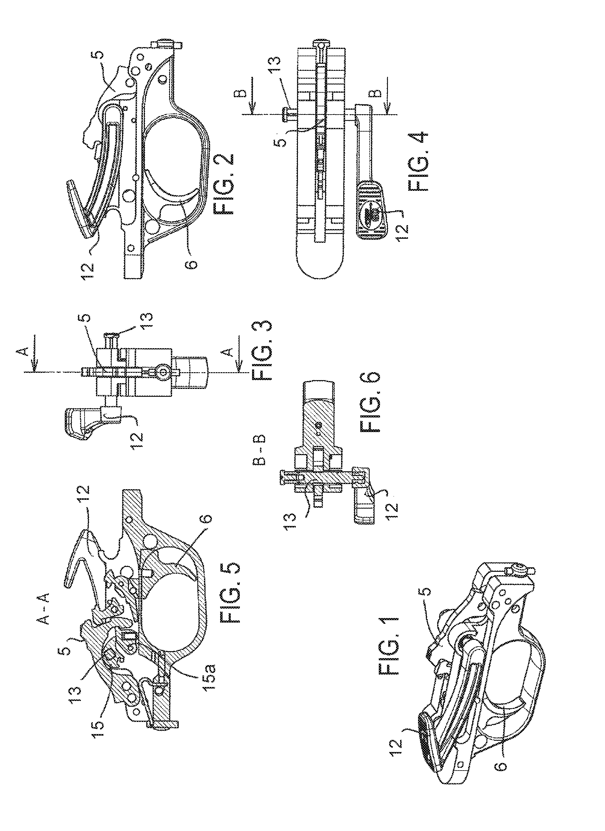
[0019] The invention is described below in more detail using the figures of the appended drawings, in which:
[0020] FIG. 1 is a perspective view of the trigger guard, in particular showing the hammer subject to the unlocking assembly,
[0021] FIG. 2 is a front view, corresponding to FIG. 1,
[0022] FIG. 3 is a side view of FIG. 2,
[0023] FIG. 4 is a top view of FIG. 1,
[0024] FIG. 5 is a longitudinal sectional view, considered along line AA of FIG. 3,
[0025] FIG. 6 is a sectional view, considered along line BB of FIG. 4.
[0026] As emerges from the teaching of document FR 3,019,887, the receiver of the firearm receives a movable assembly, not shown, essentially made up of a stopper, a latch and a striker, which is struck under the effect of the tilting of a hammer (5), controlled by a trigger (6).
[0027] The operation of this type of firearm is not described, since it is perfectly well known for one skilled in the art.
[0028] The firearm has an unlocking assembly (12), able to be actuated manually, and capable of acting directly on the hammer (5), to release the movable assembly and to allow the assisted return of said assembly for reloading. The unlocking assembly is made up of a maneuvering lever (12), accessible from outside the firearm.
[0029] More specifically, the unlocking lever (12) is subject to the hammer (5), which therefore makes up the locking means by cooperating with two parts (15) and (15a), which are capable of neutralizing the striker of the firearm, therefore making said hammer (5) inoperative.
[0030] As shown more particularly in FIG. 5, these two parts are made up of an unlocking finger (15), and an unlocking notch (15a).
[0031] The unlocking lever (12) is secured to the unlocking finger (15), using a pivot axis (13) of said lever (12), said axis being engaged transversely, FIG. 6.
[0032] More particularly, this axis (13) has a polygonal male step, for example in the form of a square, cooperating with a female cavity having a complementary shape, formed in a thickness of the unlocking finger (15).
[0033] Thus, when one acts on the unlocking lever (12), the unlocking finger (15), which cooperates by bearing with the unlocking notch (15a), acts on said notch, which has a beak cooperating with a boss of the hammer, to cause said hammer to drop.
[0034] As a result of these features, the locking at a rear position of movement of the movable part is done directly by the hammer, which constitutes a master part of the firearm.
[0035] The advantages emerge clearly from the description.
* * * * *
D00000
D00001
XML
uspto.report is an independent third-party trademark research tool that is not affiliated, endorsed, or sponsored by the United States Patent and Trademark Office (USPTO) or any other governmental organization. The information provided by uspto.report is based on publicly available data at the time of writing and is intended for informational purposes only.
While we strive to provide accurate and up-to-date information, we do not guarantee the accuracy, completeness, reliability, or suitability of the information displayed on this site. The use of this site is at your own risk. Any reliance you place on such information is therefore strictly at your own risk.
All official trademark data, including owner information, should be verified by visiting the official USPTO website at www.uspto.gov. This site is not intended to replace professional legal advice and should not be used as a substitute for consulting with a legal professional who is knowledgeable about trademark law.