Tube Pattern For A Refrigerator Evaporator
REAGEN; Scot ; et al.
U.S. patent application number 16/203843 was filed with the patent office on 2019-03-28 for tube pattern for a refrigerator evaporator. The applicant listed for this patent is Brazeway, Inc.. Invention is credited to Matt BAKER, Brian John CHRISTEN, Scott C. PETERS, Scot REAGEN, William SPROW, Gary WOLFE.
| Application Number | 20190093939 16/203843 |
| Document ID | / |
| Family ID | 65807255 |
| Filed Date | 2019-03-28 |


View All Diagrams
| United States Patent Application | 20190093939 |
| Kind Code | A1 |
| REAGEN; Scot ; et al. | March 28, 2019 |
Tube Pattern For A Refrigerator Evaporator
Abstract
A refrigeration system for a refrigerator or a freezer, comprising a compressor; a condenser; and an evaporator, wherein the evaporator includes a coil formed of a plurality of linear sections connected by a plurality of curved sections, and the coil is attached to a plurality of fins, each fin has a length and a width, and the width defines an evaporator depth; and the plurality of curved sections are arranged in a number of columns to define a tube pattern formed along the evaporator depth.
| Inventors: | REAGEN; Scot; (Sylvania, OH) ; CHRISTEN; Brian John; (Monroe, MI) ; SPROW; William; (Adrian, MI) ; PETERS; Scott C.; (Adrian, MI) ; WOLFE; Gary; (Blissfield, MI) ; BAKER; Matt; (Onsted, MI) | ||||||||||
| Applicant: |
|
||||||||||
|---|---|---|---|---|---|---|---|---|---|---|---|
| Family ID: | 65807255 | ||||||||||
| Appl. No.: | 16/203843 | ||||||||||
| Filed: | November 29, 2018 |
Related U.S. Patent Documents
| Application Number | Filing Date | Patent Number | ||
|---|---|---|---|---|
| 14643065 | Mar 10, 2015 | |||
| 16203843 | ||||
| 61950916 | Mar 11, 2014 | |||
| Current U.S. Class: | 1/1 |
| Current CPC Class: | F28D 1/024 20130101; F25B 39/02 20130101; F25B 2339/0242 20130101; F28D 1/0477 20130101; F25D 17/067 20130101; F25B 2500/01 20130101; F28F 1/26 20130101; F28F 1/32 20130101 |
| International Class: | F25D 17/06 20060101 F25D017/06; F28D 1/02 20060101 F28D001/02; F28D 1/047 20060101 F28D001/047; F28F 1/26 20060101 F28F001/26 |
Claims
1. A refrigeration system for a refrigerator or a freezer, comprising: a compressor; a condenser; and an evaporator, wherein the evaporator includes a plurality of fins and a serpentine coil attached to each of the plurality of fins, the serpentine coil being formed from a tube having a plurality of linear sections interconnected by a plurality of curved sections, each fin has a length and a width, and the width defines an evaporator depth; and the plurality of curved sections that interconnect the plurality of linear sections are arranged in a number of columns to define a tube pattern formed along the evaporator depth, the plurality of linear sections in each column are staggered to provide for air flow between the plurality of linear sections to increase heat transfer between a refrigerant carried by the serpentine coil and the air, the number of columns is selected based on the evaporator depth such that when the plurality of fins have a first evaporator depth the number of columns is at least one, when the plurality of fins have a second evaporator depth greater than the first evaporator depth the number of columns is at least two, when the plurality of fins have a third evaporator depth greater than the second evaporator depth the number of columns is at least three, and when the plurality of fins have a fourth evaporator depth greater than the third evaporator depth the number of columns is at least four, an outer diameter of the tube is in the range of 6.5 mm to 7.5 mm.
2. The refrigeration system according to 1, wherein a wall thickness of the tube is in the range of 0.3 mm to 0.7 mm.
3. The refrigeration system of claim 1, wherein the fins have the second evaporator depth, and the tube pattern includes two columns of curved sections.
4. The refrigeration system of claim 3, wherein the second evaporator depth is about 50 mm.
5. The refrigeration system of claim 1, wherein the fins have the third evaporator depth, and the tube pattern includes three columns of curved sections.
6. The refrigeration system of claim 5, wherein the third evaporator depth is about 60 mm.
7. The refrigeration system according to claim 6, wherein the columns are spaced apart in a width direction of the fin such that the fin cannot be divided into three fins having an evaporator depth of about 20 mm each having a single column of curved sections.
8. The refrigeration system of claim 5, wherein the third evaporator depth is about 75 mm.
9. The refrigeration system of claim 1, wherein the fins have the fourth evaporator depth, and the tube pattern includes four columns of curved sections.
10. The refrigeration system of claim 9, wherein the fourth evaporator depth is about 100 mm.
11. The refrigeration system of claim 1, wherein the outer diameter of the tube is about 7.0 mm.
12. The refrigeration system of claim 1, wherein a spacing between the columns is smaller than a radius of curvature of the curved sections.
13. The refrigeration system according to claim 12, wherein the radius of curvature of the curved sections is in the range of 9 to 12 mm.
14. A refrigeration system for a refrigerator or a freezer, comprising: a compressor; a condenser; and an evaporator, wherein the evaporator includes a plurality of fins and a serpentine coil attached to each of the plurality of fins, the serpentine coil being formed from a tube having a plurality of linear sections interconnected by a plurality of curved sections, each fin has a length and a width, the width defines an evaporator depth, and the width is about 60 mm; and the plurality of curved sections that interconnect the plurality of linear sections are arranged in a three columns to define a tube pattern formed along the evaporator depth, the plurality of linear sections in each column are staggered to provide for air flow between the plurality of linear sections to increase heat transfer between a refrigerant carried by the serpentine coil and the air, and an outer diameter of the tube is in the range of 6.5 mm to 7.5 mm.
15. The refrigeration system according to claim 14, wherein the three columns are spaced apart in a width direction of the fin such that the fin cannot be divided into three fins having an evaporator depth of about 20 mm each having a single column of curved sections.
16. The refrigeration system of claim 15, wherein a spacing between the three columns is smaller than a radius of curvature of the curved sections.
17. The refrigeration system according to claim 16, wherein the radius of curvature of the curved sections is in the range of 9 to 12 mm.
18. The refrigeration system of claim 14, wherein the outer diameter of the tube is about 7.0 mm.
Description
CROSS-REFERENCE TO RELATED APPLICATIONS
[0001] This application is a continuation-in-part of U.S. patent application Ser. No. 14/643,065 filed on Mar. 10, 2015, which claims priority to U.S. Provisional Patent Application No. 61/950,916 filed Mar. 11, 2014. The entire disclosures of the above applications are incorporated herein by reference.
FIELD
[0002] The present disclosure relates to a tube pattern for a refrigerator evaporator, and also relates to a refrigerator evaporator equipped with the tube pattern.
BACKGROUND
[0003] This section provides background information related to the present disclosure which is not necessarily prior art.
[0004] The cost pressure in household appliance market is extremely intense, and the increasingly strict governmental regulations are requiring the household appliance to possess even higher energy efficiency, which drives demands for more cost-beneficial and more efficient components.
[0005] In the 1990's, the tube used for a refrigerator evaporator in most of the markets was modified in its outer diameter from 9.5 mm to 8.0 mm to improve the return flow of oil being utilized with new refrigerants. Although some improvements in performance were noticed, such change has not been well understood.
[0006] It is generally known that when the diameter of a tube is decreased, the wall thickness thereof and the material consumption are also reduced, with the burst pressure being maintained. A variety of heat transfer models would suggest that it may or may not improve the heat transfer by reducing the tube diameter within the operation area of the refrigerator, but the previous change in diameter has suggested that it may involve certain improvement.
[0007] One of the severe uncertainties in further decreasing the diameter is its unknown influence to the compressor. The refrigerator evaporator is working at a condition near atmosphere pressure or of slight vacuum. When the pressure approaches absolute zero, the influence to the compressor increases, so that any increase in the pressure drop may heavily influence the compressor.
[0008] In order to reduce global warming, flammable refrigerants are becoming more prevalent in the market. It is desired to minimize the amount of refrigerants used in these applications, and in some cases government regulation limits the amount of refrigerant that can be used.
SUMMARY
[0009] This section provides a general summary of the disclosure, and is not a comprehensive disclosure of its full scope or all of its features.
[0010] According to a first aspect, the present disclosure provides a refrigeration system for a refrigerator or a freezer that includes a compressor; a condenser; and an evaporator. The evaporator includes a plurality of fins and a serpentine coil attached to each of the plurality of fins. The serpentine coil is formed from a tube having a plurality of linear sections interconnected by a plurality of curved sections. Each fin has a length and a width, and the width defines an evaporator depth. The plurality of curved sections that interconnect the plurality of linear sections are arranged in a number of columns to define a tube pattern formed along the evaporator depth. The plurality of linear sections in each column are staggered to provide for air flow between the plurality of linear sections to increase heat transfer between a refrigerant carried by the serpentine coil and the air. The number of columns is selected based on the evaporator depth such that when the plurality of fins have a first evaporator depth the number of columns is at least one, when the plurality of fins have a second evaporator depth greater than the first evaporator depth the number of columns is at least two, when the plurality of fins have a third evaporator depth greater than the second evaporator depth the number of columns is at least three, and when the plurality of fins have a fourth evaporator depth greater than the third evaporator depth the number of columns is at least four, and an outer diameter of the tube is in the range of 6.5 mm to 7.5 mm.
[0011] According to the first aspect of the present disclosure, a wall thickness of the tube may be in the range of 0.3 mm to 0.7 mm.
[0012] According to the first aspect of the present disclosure, the fins may have the second evaporator depth, and the tube pattern may include two columns of curved sections.
[0013] According to the first aspect of the present disclosure, the second evaporator depth may be about 50 mm.
[0014] According to the first aspect of the present disclosure, the fins may have the third evaporator depth, and the tube pattern may include three columns of curved sections.
[0015] According to the first aspect of the present disclosure, the third evaporator depth may be about 60 mm.
[0016] According to the first aspect of the present disclosure, the columns may be spaced apart in a width direction of the fin such that the fin cannot be divided into three fins having an evaporator depth of about 20 mm each having a single column of curved sections.
[0017] According to the first aspect of the present disclosure, the third evaporator depth may be about 75 mm.
[0018] According to the first aspect of the present disclosure, the fins may have the fourth evaporator depth, and the tube pattern may include four columns of curved sections.
[0019] According to the first aspect of the present disclosure, the fourth evaporator depth may be about 100 mm.
[0020] According to the first aspect of the present disclosure, the outer diameter of the tube may be about 7.0 mm.
[0021] According to the first aspect of the present disclosure, a spacing between the columns may be smaller than a radius of curvature of the curved sections.
[0022] According to the first aspect of the present disclosure, the radius of curvature of the curved sections may be in the range of 9 to 12 mm.
[0023] According to a second aspect of the present disclosure, there is provided a refrigeration system for a refrigerator or a freezer that includes a compressor; a condenser; and an evaporator. The evaporator includes a plurality of fins and a serpentine coil attached to each of the plurality of fins, and the serpentine coil may be formed from a tube having a plurality of linear sections interconnected by a plurality of curved sections. Each fin has a length and a width, the width defines an evaporator depth, and the width may be about 60 mm. The plurality of curved sections that interconnect the plurality of linear sections may be arranged in a three columns to define a tube pattern formed along the evaporator depth, the plurality of linear sections in each column are staggered to provide for air flow between the plurality of linear sections to increase heat transfer between a refrigerant carried by the serpentine coil and the air, and an outer diameter of the tube may be in the range of 6.5 mm to 7.5 mm.
[0024] According to the second aspect of the present disclosure, the three columns may be spaced apart in a width direction of the fin such that the fin cannot be divided into three fins having an evaporator depth of about 20 mm each having a single column of curved sections.
[0025] According to the second aspect of the present disclosure, a spacing between the three columns may be smaller than a radius of curvature of the curved sections.
[0026] According to the second aspect of the present disclosure, the radius of curvature of the curved sections may be in the range of 9 to 12 mm.
[0027] According to the second aspect of the present disclosure, the outer diameter of the tube may be about 7.0 mm.
[0028] Further areas of applicability will become apparent from the description provided herein. The description and specific examples in this summary are intended for purposes of illustration only and are not intended to limit the scope of the present disclosure.
DRAWINGS
[0029] All the technical features of the present disclosure will become more apparent from the accompanying drawings. The drawings described herein are for illustrative purposes only of selected embodiments and not all possible implementations, and are not intended to limit the scope of the present disclosure.
[0030] FIG. 1 illustrates an example refrigerator/freezer including a refrigeration system according to the present disclosure;
[0031] FIG. 2 is a schematic representation of a refrigeration system according to the present disclosure;
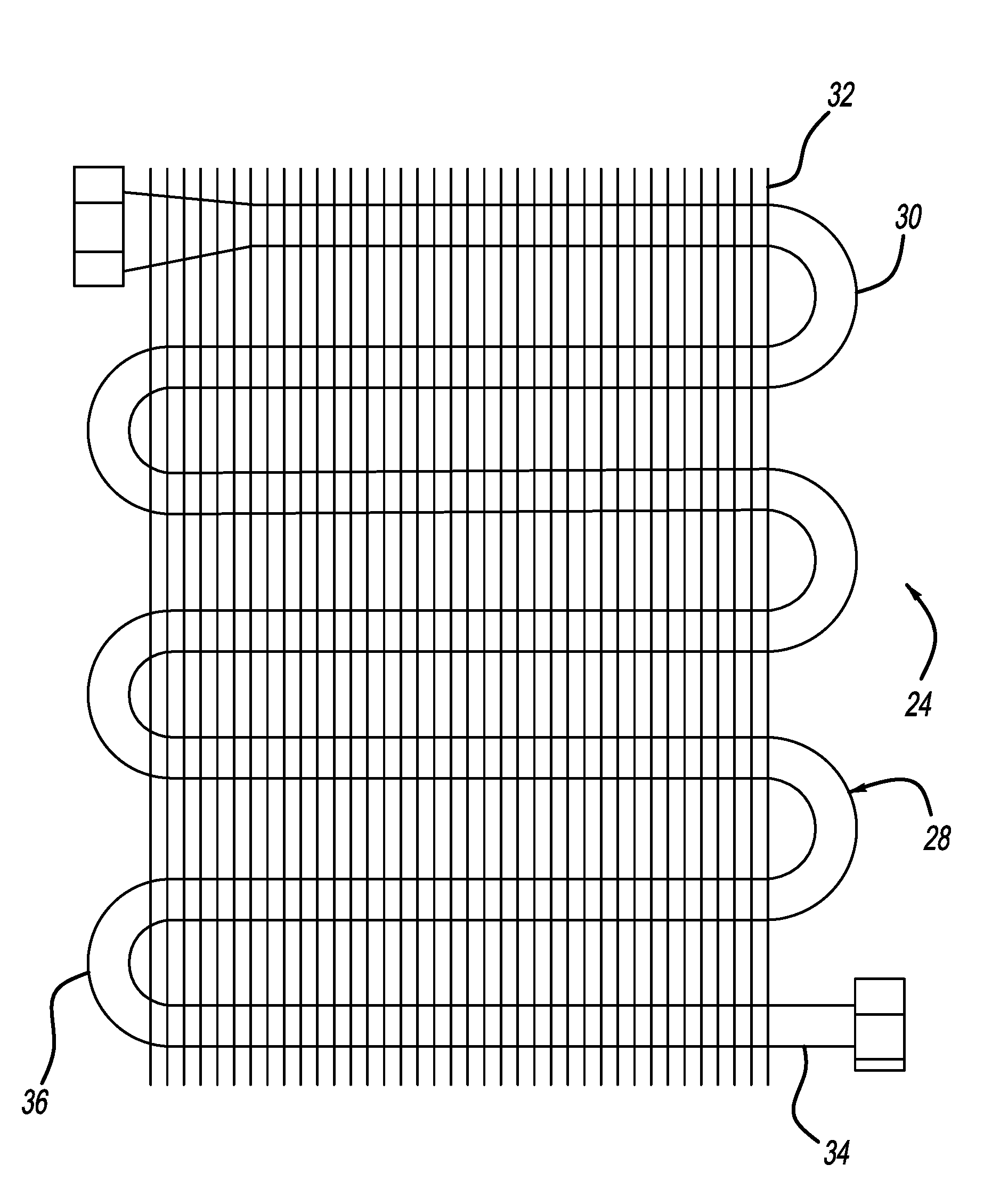
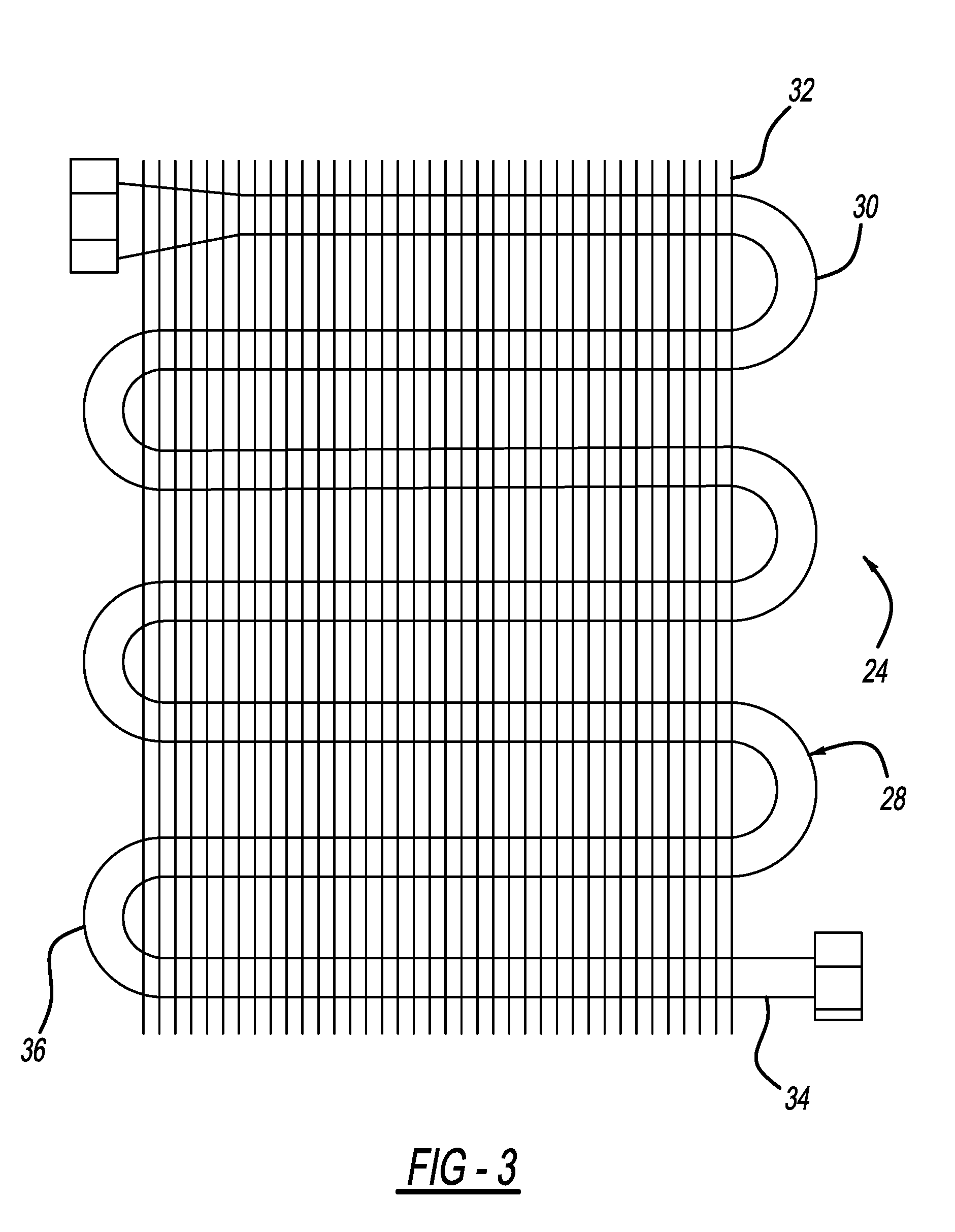
[0032] FIG. 3 illustrates an evaporator of the refrigeration system illustrated in FIG. 2;
[0033] FIG. 4 is a front perspective view of the evaporator illustrated in FIG. 3;
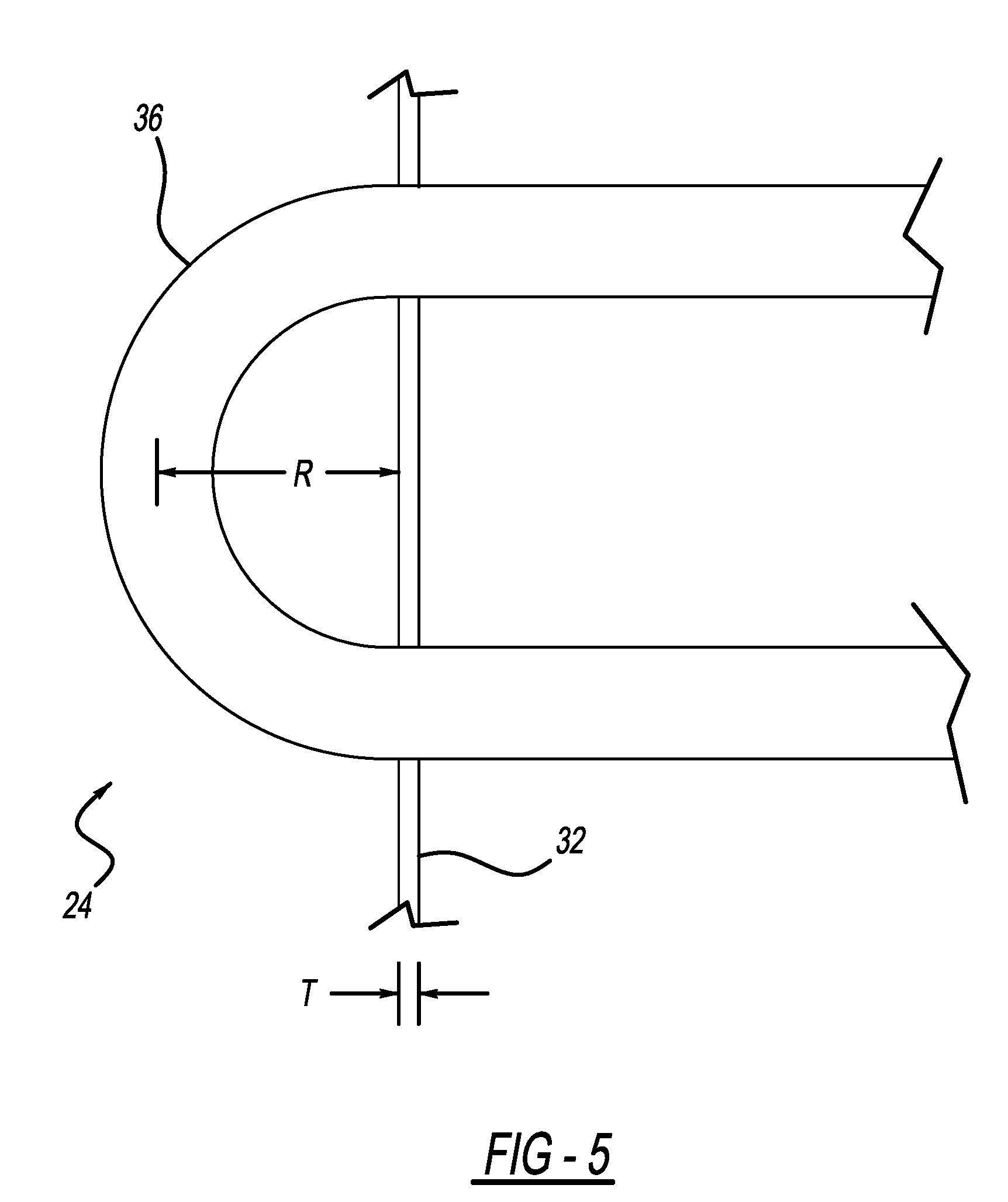
[0034] FIG. 5 is a partial side-perspective view of the evaporator illustrated in FIG. 3;
[0035] FIG. 6 illustrates another evaporator with a depth of about 75 mm and three columns of curved sections according to a principle of the present disclosure;
[0036] FIG. 7 illustrates another evaporator with a depth of about 50 mm and two columns of curved sections according to a principle of the present disclosure;
[0037] FIG. 8 illustrates another evaporator with a depth of about 60 mm and three columns of curved sections according to a principle of the present disclosure;
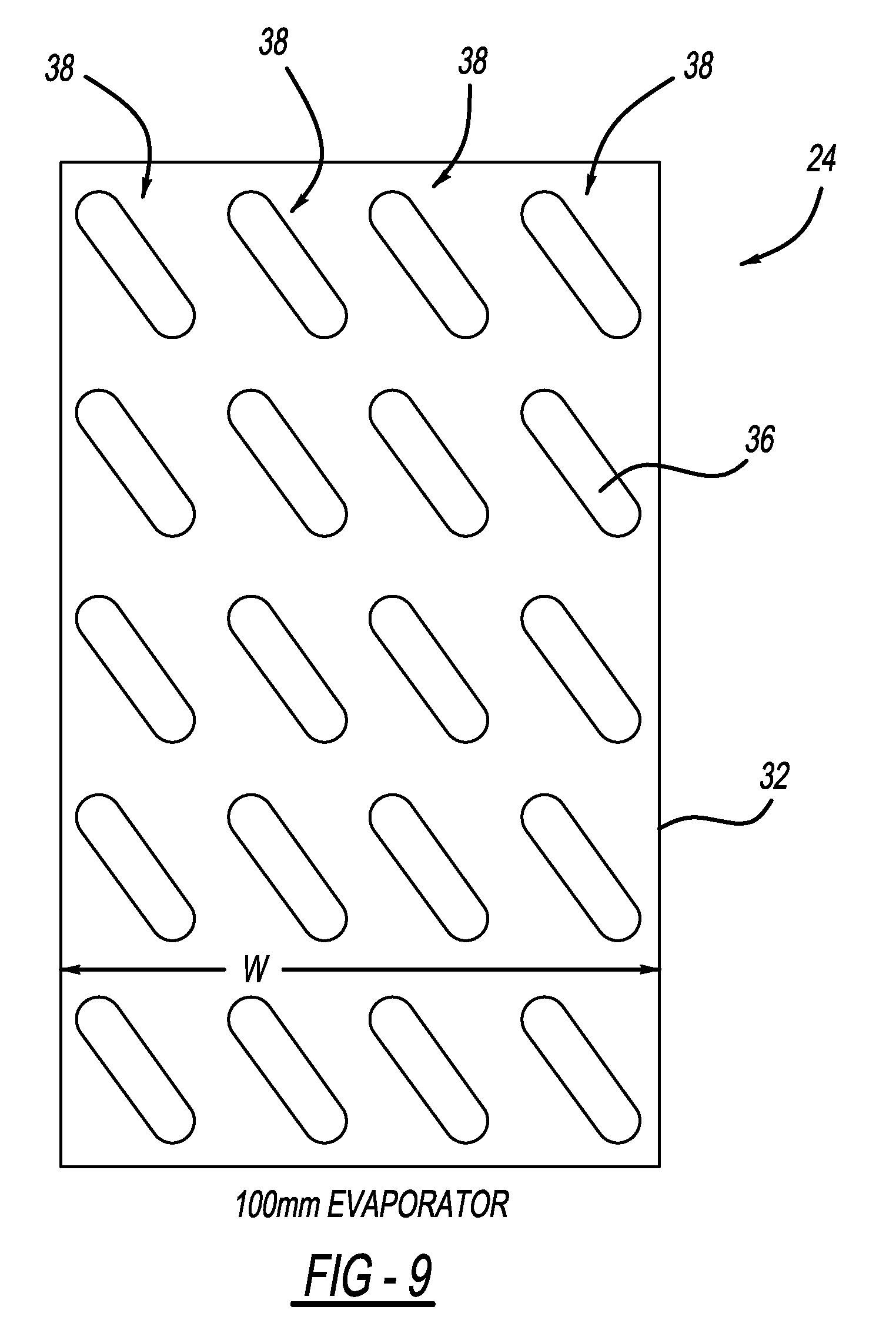
[0038] FIG. 9 illustrates another evaporator with a depth of about 100 mm and four columns of curved sections according to a principle of the present disclosure;
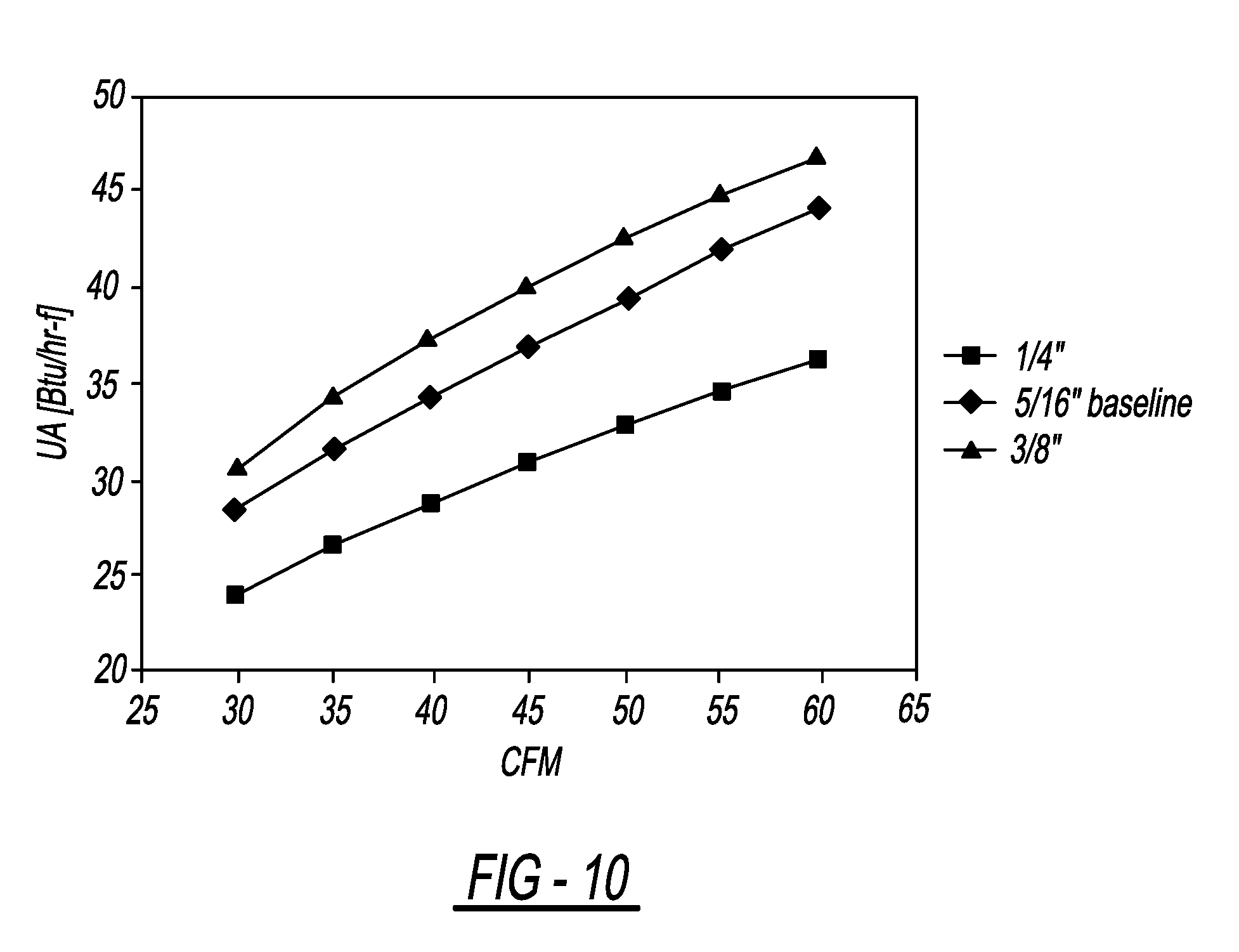
[0039] FIG. 10 is a graph illustrating the amount of heat transfer that is achieved using evaporators having tube diameters of 1/4 inches (6.35 mm), 5/16 inches (8 mm), and 3/8 inches (9.5 mm), respectively;
[0040] FIGS. 11-13 are graphs illustrating the evaluation of influence to the heat transfer and pressure drop performance caused by the tube outer diameter, representing three types of tubes with different outer diameters which are 6.35 mm, 8.00 mm and 9.50 mm, respectively;
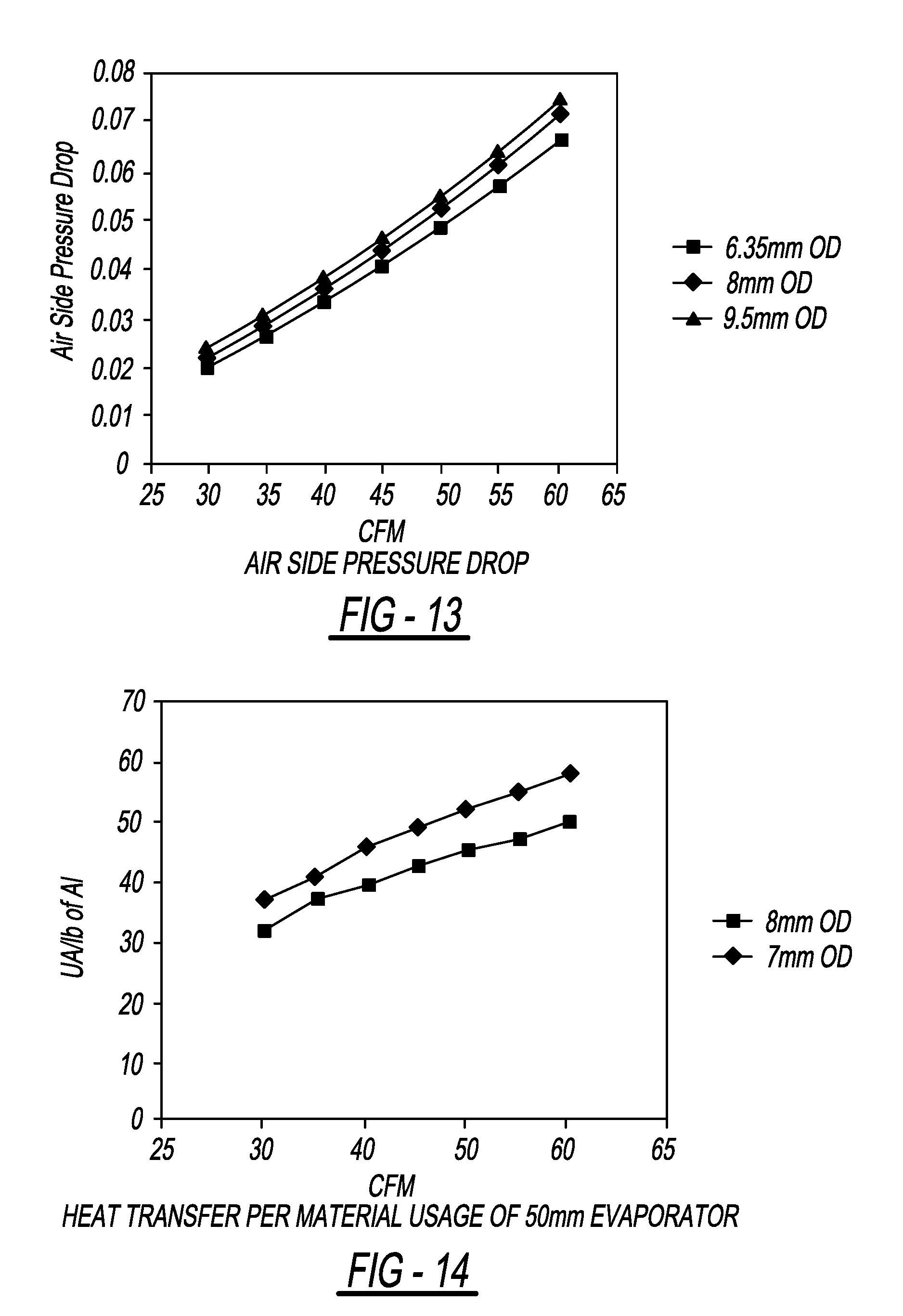
[0041] FIGS. 14 and 15 graphically illustrate the comparison between a 7.00 mm tube and a 8.00 mm tube arranged on an evaporator with a depth of about 50 mm and 2 columns of tubes;
[0042] FIG. 16 and FIG. 17 graphically illustrate the comparison between an evaporator with a depth of about 60 mm and 2 columns of 8 mm tubes and an evaporator with a depth of about 60 mm and 3 columns of 7 mm tubes;
[0043] and
[0044] FIG. 18 illustrates normalized energy results obtained by testing three refrigerators using evaporators having tube diameters of 5/16'', 7 mm, and 1/4''.
[0045] Corresponding reference numerals indicate corresponding parts throughout the several views of the drawings.
DETAILED DESCRIPTION
[0046] Example embodiments will now be described more fully with reference to the accompanying drawings. For those skilled in the art, all the features and advantage of the present utility model will become more apparent from the accompanying drawings and corresponding description.
[0047] Example embodiments are provided so that this disclosure will be thorough, and will fully convey the scope to those who are skilled in the art. Numerous specific details are set forth such as examples of specific components, devices, and methods, to provide a thorough understanding of embodiments of the present disclosure. It will be apparent to those skilled in the art that specific details need not be employed, that example embodiments may be embodied in many different forms and that neither should be construed to limit the scope of the disclosure. In some example embodiments, well-known processes, well-known device structures, and well-known technologies are not described in detail.
[0048] The terminology used herein is for the purpose of describing particular example embodiments only and is not intended to be limiting. As used herein, the singular forms "a," "an," and "the" may be intended to include the plural forms as well, unless the context clearly indicates otherwise. The terms "comprises," "comprising," "including," and "having," are inclusive and therefore specify the presence of stated features, integers, steps, operations, elements, and/or components, but do not preclude the presence or addition of one or more other features, integers, steps, operations, elements, components, and/or groups thereof. The method steps, processes, and operations described herein are not to be construed as necessarily requiring their performance in the particular order discussed or illustrated, unless specifically identified as an order of performance. It is also to be understood that additional or alternative steps may be employed.
[0049] When an element or layer is referred to as being "on," "engaged to," "connected to," or "coupled to" another element or layer, it may be directly on, engaged, connected or coupled to the other element or layer, or intervening elements or layers may be present. In contrast, when an element is referred to as being "directly on," "directly engaged to," "directly connected to," or "directly coupled to" another element or layer, there may be no intervening elements or layers present. Other words used to describe the relationship between elements should be interpreted in a like fashion (e.g., "between" versus "directly between," "adjacent" versus "directly adjacent," etc.). As used herein, the term "and/or" includes any and all combinations of one or more of the associated listed items.
[0050] Although the terms first, second, third, etc. may be used herein to describe various elements, components, regions, layers and/or sections, these elements, components, regions, layers and/or sections should not be limited by these terms. These terms may be only used to distinguish one element, component, region, layer or section from another region, layer or section. Terms such as "first," "second," and other numerical terms when used herein do not imply a sequence or order unless clearly indicated by the context. Thus, a first element, component, region, layer or section discussed below could be termed a second element, component, region, layer or section without departing from the teachings of the example embodiments.
[0051] Spatially relative terms, such as "inner," "outer," "beneath," "below," "lower," "above," "upper," and the like, may be used herein for ease of description to describe one element or feature's relationship to another element(s) or feature(s) as illustrated in the figures. Spatially relative terms may be intended to encompass different orientations of the device in use or operation in addition to the orientation depicted in the figures. For example, if the device in the figures is turned over, elements described as "below" or "beneath" other elements or features would then be oriented "above" the other elements or features. Thus, the example term "below" can encompass both an orientation of above and below. The device may be otherwise oriented (rotated 90 degrees or at other orientations) and the spatially relative descriptors used herein interpreted accordingly.
[0052] FIG. 1 illustrates an example refrigerator/freezer 10 including an upper enclosure 12 and a lower enclosure 14 for storing food or other articles to be cooled or frozen. Upper enclosure 12 may be a freezer compartment, and lower enclosure 14 may be a refrigerating compartment. Refrigerator/freezer 10 includes a casing 16 that defines each of the upper enclosure 12 and lower enclosure 14, while also housing a refrigeration system 18 that is schematically illustrated in FIG. 2. Although refrigerator/freezer 10 is described as including an upper enclosure 12 and a lower enclosure 14, it should be understood that the refrigerator/freezer 10 can include side-by-side enclosures, only include a refrigerator compartment, only include a freezer compartment, or be any other type of combination refrigeration and freezer that is known to one skilled in the art.
[0053] Referring to FIG. 2, refrigeration system 18 may generally include a compressor 20, a condenser 22, and an evaporator 24 that are connected by connection lines 26. Disposed between condenser 22 and evaporator 24 may be an expansion device 27 such as a valve or capillary tube. Compressor 20 receives low-pressure refrigerant from evaporator 16 through one of the connection lines 26 at a suction side and dispenses high-pressure refrigerant at a discharge side through another of the connection lines 26 to condenser 14.
[0054] During refrigeration, refrigeration system 18 uses the cooling effect of evaporation of the refrigerant to lower the temperature of the surroundings near one heat exchanger (i.e., evaporator 24) and uses the heating effect of high pressure, high temperature gas to raise the temperature of the surroundings near another heat exchanger (i.e., condenser 22). This is usually accomplished by releasing a refrigerant under pressure (usually in a liquid phase) into a low pressure region to cause the refrigerant to expand into a low temperature mixture of liquid and vapor. Commonly, this low pressure region comprises a coil 28 that forms part of evaporator 24. Once in the evaporator coil 28, the refrigerant mixture may exchange heat with the tubing 30 of the coil 28, which in turn exchanges heat with high temperature ambient air of the region desired to be cooled. Evaporation of refrigerant from liquid to gas absorbs heat from the ambient air and thereby cools it.
[0055] Referring to FIG. 3, an evaporator 24 of refrigeration system 18 is illustrated. Evaporator 24 includes coil 28 which includes tubing 30 that meanders back and forth in a serpentine pattern through a plurality of spaced apart fins 32. Fins 32 assist tubing 30 with exchanging heat from the refrigerant mixture to the ambient air, and are attached to tubing 30 either mechanically (e.g., press-fit) or by brazing as is known in the art. Fins 32 are spaced apart to allow for air to flow between fins 32 and around tubing 30. Fins 32 and tubing 30 may be formed of aluminum, or any other known heat exchange material. Fins 32 are generally rectangular-shaped members having a length L, a width W, and a thickness T, wherein the width W defines a depth of the evaporator 24.
[0056] FIG. 4 is a front perspective view of the evaporator 24 illustrated in FIG. 3. As shown in FIG. 4, fin 32 includes length L, which in the illustrated embodiment is about 125 mm. It should be understood, however, that length L of fin 32 is variable and can be any length L desired. Fin 32 also includes a width W of about 25 mm. Fin 32, therefore, defines an evaporator depth of about 25 mm.
[0057] The tubing 30 of coil 28 may include a single tube that includes a plurality of linear sections 34 that are interconnected by curved sections 36. Alternatively, coil 28 may be formed of a plurality of linear tubes (sections) 34 that are attached to hairpin tubes (curved sections) 36 by brazing in substantially the same manner as fins 32 are attached to tubing 30. As shown in FIG. 4, the evaporator 24 includes a single column 38 of curved sections 36. Moreover, curved sections 36 may be arranged at an inclined orientation with respect to the evaporator depth (i.e., width W) such that adjacent linear sections 34 are staggered, which improves the flow of air between linear sections 34 and fins 32, thereby providing optimal heat transfer. The angle of inclination theta (.crclbar.) may range between twenty-five degrees and seventy-five degrees relative an edge 40 of fin 32. Preferably, the angle of inclination theta (.crclbar.) may range between 30 degrees and seventy degrees relative an edge 40 of fin 32. In the illustrated embodiments, the angle of inclination is about forty-five degrees. Moreover, as best shown in FIG. 5, curved sections 36 are bent such that a radius of curvature (R) of the curved sections 36 ranges between 9.0 mm to 12.0 mm. In this manner, curved sections 36 are bent as tightly as possible, with high bending quantity, to ensure that the greatest number of linear sections 34 can be used to form coil 28 of evaporator 24.
[0058] The present disclosure is also directed to evaporators 24 having multiple columns 38 of curved sections 36. As best shown in FIGS. 6-9, evaporators 24 having two columns 38 of curved sections 36, three columns 38 of curved sections 36, and four columns 38 of curved sections 36 are illustrated. It should be understood, however, that the number of columns 38 can be greater than four, without departing from the scope of the present disclosure.
[0059] In FIG. 6, which illustrates an evaporator 24 having three columns 38 of curved sections 36, the fins 32 have a width W of about 75 mm. FIG. 7 illustrates an evaporator 24 having two columns 38 of curved sections 36, where the fins 32 have a width W of about 50 mm. FIG. 8 illustrates an evaporator 24 having three columns 38 of curved sections 36, where the fins 32 have a width W of about 60 mm. Lastly, FIG. 9 illustrates an evaporator 24 having four columns 38 of curved sections 36, where the fins 32 have a width W of about 100 mm.
[0060] Regardless, it should be understood the refrigeration system 18 utilizes an evaporator 24 that includes either a single column 38 of curved sections 36 (FIG. 4), or multiple columns 38 of curved sections 36. If multiple columns 38 of curved sections 36 are used, it should be understood that a column 38 of curved sections 36 is used for every 15 to 30 mm of fin 32 width W, preferably for every 18 to 27 mm of fin 32 width W, and most preferably for every 20 to 25 mm of fin 32 width W. Thus, an evaporator 24 having a depth (fin width W) of about 50 mm may include two columns 38 of curved sections 36; an evaporator 24 having a depth (fin width W) of about 60 mm may include three columns 38 of curved sections 36; an evaporator 24 having a depth (fin width W) of about 75 mm may include three columns 38 of curved sections 36; and an evaporator 24 having a depth (fin width W) of about 100 mm may include either four or five columns 38 of curved sections 36.
[0061] The selection of the number of columns 38 of curved sections 36 is system dependent. In this regard, the size of the evaporator 24 is selected on the size of the refrigeration/freezer 10. For example, a smaller refrigerator/freezer 10 may require a smaller evaporator such as the evaporator 24 illustrated in FIG. 4 having only a single column 38 of curved sections 36. In a larger refrigerator/freezer 10, a larger evaporator 24 may be selected such as the evaporators 24 illustrated in any of FIGS. 6-9 that each have multiple columns 38 of curved sections 36. Regardless, the appropriate evaporator 24 should be selected based on the desired amount of maximum heat exchange capability in conjunction with the effect on the compressor 20.
[0062] When evaporator 24 includes multiple columns 38 of curved sections 36, it should be understood that the columns 38 of curved sections 36 may be spaced apart in a width W direction of the fin 32 in a manner such that the fin 32 cannot be subsequently divided into multiple fins 32 that each have a single column 38 of curved sections 36. This is accomplished by having the columns 38 of curved sections 36 be spaced apart at a distance that is less than the radius of curvature R of the curved sections 36. For example, FIG. 8 illustrates a 60 mm evaporator 24 having three columns 38 of curved sections 36 that are spaced apart from each other such that fin 32 cannot be divided into three fins 32 each having a width W (i.e., evaporator depth) of about 20 mm and each having a single column 38 of curved sections. By spacing the multiple columns 38 of curved sections 36 apart in this manner, evaporator 24 will have a compact design while still maintaining a maximum amount of heat transfer capability. Alternatively, the columns 38 of curved sections 36 may be spaced apart at a distance that is greater than the radius of curvature R of the curved sections 36. Such a spacing between columns 38 of curved sections 36 may be used with evaporators 24 having a width W (evaporator depth) of about 50 mm, about 75 mm, about 100 mm, and greater.
[0063] In addition to arranging curved sections 36 at an inclined orientation with respect to the evaporator depth (i.e., width W) such that adjacent linear sections 34 are staggered to improve the flow of air between the linear sections 34 and the fins 32 to provide maximum heat transfer, and in addition to spacing multiple columns 38 of the curved sections 36 in a manner that achieves a compact design while still maintaining a maximum amount of heat transfer, the evaporator 24 used in the refrigeration system 18 according to the present disclosure also utilizes linear sections 34 and curved sections 36 that have an outer diameter that ranges between 6.5 mm to 7.5 mm, inclusive. In addition, a wall thickness of the linear and curved sections 34 and 36 ranges between 0.3 mm to 0.7 mm as required by a burst pressure. Use of linear and curved sections 34 and 36 having these dimensions reduces the material manufacturing costs, and also further reduces internal volume required refrigerant charge.
[0064] During development of refrigeration system 18 of the present disclosure, two unexpected results were encountered during design of evaporator 24. A first unexpected result was that the heat transfer performance of evaporator 24 was much greater than expected.
[0065] More particularly, one skilled in the art of evaporators for heat transfer will readily acknowledge and appreciate that a widely accepted correlation for heat transfer around a cylinder (i.e., a tube) was developed by Hilpert and is commonly referenced in textbooks and technical papers. The correlation for heat transfer developed by Hilpert is as follows:
Nu=CRe.sup.mPr.sup.1/3 (1)
[0066] In equation (1), Nu=h D/k (Nusselt number), Re=.rho.VD/.mu. (Reynolds number), and Pr=Cp .mu./k (Prandtl number). Further, h represents a heat transfer coefficient, D represents a diameter of a cylinder, K represents the air thermal conductivity, .rho. represents the air density, V represents the air velocity, and .mu. represents the air viscosity.
[0067] Moreover, the constants C and m are dependent upon Re as shown in the below Table 1.
TABLE-US-00001 TABLE 1 Re C m 0.4-4 0.989 0.330 4-40 0.911 0.385 40-4000 0.683 0.466 4000-40,000 0.193 0.618 40,000-400,000 0.027 0.805
[0068] With the above in mind, FIG. 10 shows the measured amount of heat transfer that can be achieved using an evaporator 24 having linear and curved section tube diameters of 1/4 inches (6.35 mm), 5/16 inches (8 mm), and 3/8 inches (9.5 mm), and two columns 38 of tubes. In FIG. 10, the term "UA" represents the overall heat transfer coefficient and can be broken downs as it relates to the tubes 34 and 36 and fin 32 of the evaporator 24 as follows:
UA=h.sub.TA.sub.T+h.sub.fA.sub.f (2)
[0069] In equation (2), the terms h.sub.T and A.sub.T represent the heat transfer coefficient and surface area of the linear and curved sections 34 and 36, respectively, and the terms h.sub.f and A.sub.f represent the heat transfer coefficient (including fin efficiency and fin-tube contact) and surface area of the fin 32, respectively.
[0070] The heat transfer analysis was performed at 45 CFM (cubic feet per minute), a common flow rate for a refrigerator or freezer evaporator. The UA values from the data set above and the heat transfer coefficient of the linear and curved sections 34 and 36 from Hilpert's correlation are utilized to calculate the heat transfer coefficient across the fin 32.
TABLE-US-00002 TABLE 2 Tube OD Re Nu h.sub.T A.sub.T A.sub.f UA h.sub.f 1/4'' 465.2 10.78 7.51 1.22 7.99 30.9 2.7 5/16'' 582.4 11.97 6.66 1.53 9.72 36.9 2.7 3/8'' 697.8 13.02 6.05 1.83 11.27 40.1 2.6
[0071] As can be seen from the above calculations, the heat transfer coefficient (h.sub.f) of the fin 32 varies less than 4%, and that any one data set can be used to accurately predict one of the other data sets by simply adjusting the heat transfer coefficient (h.sub.T) of the tubes 34 and 36 per Hilpert's correlation. In fact, one skilled in the art will appreciate that this is a common method of using data to empirically predict the performance of a heat exchanger such as evaporator 24 in comparison to another with only a minor difference, such as a difference in tube diameter.
[0072] This methodology can now be applied to the design depicted in, for example, FIG. 8 of the patent application where the fin has an evaporator depth of about 60 mm, and there are three columns 38 of curved sections 36 (i.e., one column 38 of curved sections 36 for every 20 mm of evaporator depth). First, the fin heat transfer coefficient (h.sub.f) was determined per the method above for a typical 5/16'' tube design that includes a 60 mm evaporator depth and two columns of curved sections, and a 7 mm design having the column configuration illustrated in FIG. 8. Then, attempts were made to predict the 7 mm performance utilizing the heat transfer coefficient of the fin (h.sub.f) from the 5/16'' data and the heat transfer coefficient of the tube (h.sub.T) per Hilpert's correlation.
[0073] Based on the above and common practice it would be expected that the heat transfer coefficient UA could be accurately predicted for the 7 mm design utilizing the above methodology. Please note, however, that the actual data obtained for a heat exchanger manufactured with the design of FIG. 8 and a 7 mm tube yielded a heat transfer coefficient that was different from what was predicted using the above methodology. The results are shown below, in Table 3.
TABLE-US-00003 TABLE 3 Tube OD UA source Re Nu h.sub.T A.sub.T A.sub.f UA h.sub.f Standard 5/16'' design Data 582.4 11.97 6.66 2.30 11.85 45.5 2.53 FIG. 8, 7 mm design Data 511.3 11.27 7.14 3.20 11.23 57.4 3.05 FIG. 8, 7 mm design Predicted 511.3 11.27 7.14 3.2 11.23 51.5 2.53
[0074] As can be seen from Table 3, the fin heat transfer coefficients (h.sub.f) calculated from the experimental data utilizing the above methodology varied widely. Moreover, Table 3 indicates that if the data from the standard 5/16'' design were used to predict the performance of the evaporator 24 illustrated in FIG. 8, it would be largely inaccurate. Indeed, utilizing the 5/16'' data predicted a performance improvement of 14% (UA.sub.predicted=51.5), while the actual design provided a 27% improvement (UA.sub.actual=57.4). Thus, the evaporator 24 of FIG. 8 clearly and unexpectedly outperforms what would be predicted by one skilled in the art.
[0075] A second unexpected result is the effect of the design of the evaporator 24 on overall performance of refrigeration system 18. In this regard, it is well accepted in the industry that for every 10% change in heat transfer coefficient UA, the energy performance of a refrigerator or freezer (i.e., refrigeration system 18) will change 1%. While one skilled in the art will understand that there is some variation in this rule of thumb, this effect on energy performance has generally held true for decades across the industry.
[0076] As can be seen from the above analysis, smaller tube diameters yield a higher heat transfer coefficient UA. Smaller tube diameters also allow for tighter bend diameters and increases in burst pressure so that thinner wall thicknesses can be utilized to provide a more compact and material-efficient design. In addition, smaller tube diameters have a much higher ratio of surface area to internal volume. Hence, to provide the same heat transfer surface area, much less internal volume is required, which results in a reduced refrigerant charge. Reducing the refrigerant charge not only saves cost on the refrigerant itself, but is also known to improve energy performance due to reduced cyclic losses. It is desirable, therefore, to reduce tube diameters to capture these benefits.
[0077] Two evaporators each having three columns of curved sections and an evaporator depth of about 75 mm were prepared that utilized a 5/16'' tube and a 1/4'' tube, respectively, such that the heat transfer coefficients UA of the designs were equivalent (i.e., no impact on energy performance would be anticipated). The UA values were confirmed by calorimeter (wind tunnel) testing.
[0078] Three refrigerators were utilized to test both designs. Energy values after optimizing the refrigerant charge were:
TABLE-US-00004 TABLE 4 5/16'' 1/4'' % Difference Refrigerator #1 1.772 1.824 3.0% Refrigerator #2 1.680 1.755 4.5% Refrigerator #3 1.710 1.789 4.6%
[0079] It should be noted that the 1/4'' design reduced refrigerant charge by 10% compared to the 5/16'' design.
[0080] The heat transfer performance would have predicted no change in energy and the reduced refrigerant charge could improve energy, so such a large degradation was highly unexpected.
[0081] The data was deeply analyzed and it was determined that the 1/4'' design placed too much restriction on the compressor of the refrigerator, and that there was a "sweet spot" to take full advantage of smaller tube diameters while not restricting the compressor. The analysis showed that a diameter of 0.275'' was optimal, which was later changed to a nominal 7 mm (0.276'').
[0082] An evaporator utilizing 7 mm tube was designed to have the same UA value as the previous 5/16'' and 1/4'' designs (i.e., three columns of curved sections and an evaporator depth of about 75 mm). Again, the same UA values for these designs were confirmed by calorimeter testing.
[0083] The three refrigerators were tested again with the following energy results:
TABLE-US-00005 TABLE 5 5/16'' 7 mm % Difference Refrigerator #4 1.815 1.824 0.5% Refrigerator #5 1.729 1.754 1.4% Refrigerator #6 1.780 1.797 0.9%
[0084] The results for both tests are graphed (FIG. 18) with the data being normalized such that the 5/16'' design has a UA value of 1.0. As shown in FIG. 18, the actual results vary from the predicted results, and reducing the tube diameter below 7 mm has detrimental effects, which is unexpected. Indeed, on average, the 7 mm performed within 1% of the 5/16'' design, with 1% considered the accuracy of the test.
[0085] It should be noted that the 7 mm evaporator was significantly smaller and lighter than the 5/16'' design, providing both a 17% space savings and a 26% material savings.
[0086] The technology can also be utilized to improve energy performance by matching the size of the 7 mm evaporator to that of the existing 5/16'' evaporator. In fact, the design of FIG. 8 offers energy improvements of 2% to 4%. This follows the rule of thumb noted above that for every 10% change in heat transfer coefficient UA, the energy performance of a refrigerator (i.e., overall system) will change 1%. It is evaporators with diameters below 7 mm that do not.
[0087] Two refrigerators were tested with evaporators having tubing with 5/16'' diameter and 7 mm diameter, and the configuration illustrated in FIG. 8. The results can be seen below in Table 6 where energy values after optimizing the refrigerant charge were:
TABLE-US-00006 TABLE 6 5/16'' 7 mm % Difference Refrigerator #1 1.150 1.114 -2.1% Refrigerator #2 1.124 1.104 -1.8%
[0088] As can be seen in Table 6, the configuration of FIG. 8 when used in combination with a tube having a diameter of 7 mm takes full advantage of the heat transfer benefit of a smaller diameter tube that does not adversely affect the compressor, and delivers a reduction in energy usage.
[0089] Hereinafter the influence to heat transfer and pressure drop performance caused by the outer diameter of the tubes is evaluated by referring to FIG. 11 through FIG. 13. Two types of measurement criteria are primarily used herein. A first criteria is UA per pound (Ib) of aluminum, embodied in a heat transfer amount obtained per material usage. A second criteria is UA per volume, representing a heat transfer amount that can be obtained from a given space.
[0090] FIG. 11 through FIG. 13 show three types of tubes with different outer diameters which are 6.35 mm, 8.00 mm and 9.50 mm, respectively; wherein the X-axis in FIG. 11 through FIG. 13 represents CFM (Cubic Feet per Minute); the Y-axis in FIG. 11 represents UA/lb; the Y-axis in FIG. 12 represents UA per volume; and the Y-axis in FIG. 13 represents air side pressure drop.
[0091] As can be seen from FIG. 11 through FIG. 13, the smaller the outer diameter of the tube 30 is, the higher the UA/lb of aluminum and UA per volume are, with the decrease of the air side pressure drop. These factors realize improvement in performance and/or decrease in cost.
[0092] As also can be seen from FIG. 11 through FIG. 13, the evaporator 24 arranged with a 6.35 mm tube is similar to the evaporator arranged with 8.00 mm tube in the heat transfer performance. In addition, in several tests of refrigerator evaporators 24, evaporators provided with 6.35 mm tubes can increase the energy consumption by 4%, on average.
[0093] The inventors, therefore, have found that a 7.00 mm tube can provide beneficial advantages of a decreased tube diameter without any negative influence to the performance of compressor 20, and can maintain the energy efficiency and dramatically reduce the material consumption.
[0094] Hereinafter the influences to performance of heat transfer caused by using 7.00 mm tubes and 8.00 mm tubes are evaluated by referring to FIG. 14 through FIG. 17.
[0095] FIG. 14 and FIG. 15 show a comparison between a 7.00 mm tube and an 8.00 mm tube arranged on an evaporator with a depth of about 50 mm and two columns of tubes. It can be seen that, compared with an 8.00 mm tube, the 7.00 mm tube improves the UA/lb by 14% and improves the UA per volume by 12%.
[0096] FIG. 16 and FIG. 17 show a comparison between an evaporator with a depth of about 60 mm and two columns of 8 mm tubes, and an evaporator with a depth of about 60 mm and three columns of 7 mm tubes.
[0097] As it can be seen from FIG. 16 and FIG. 17, the 7 mm tube is designed to have a UA/lb (the heat transfer amount obtained per material usage) higher than that of an 8 mm tube by 33%, and have a UA per volume (the heat transfer amount that can be obtained from a given space) higher than that of the 8 mm tube by 31%. Thus, the overall performance of the system is unexpected.
[0098] While specific examples have been described in the specification and illustrated in the drawings, it will be understood by those of ordinary skill in the art that various changes may be made and equivalents may be substituted for elements thereof without departing from the scope of the present disclosure as defined in the claims. Furthermore, the mixing and matching of features, elements and/or functions between various examples is expressly contemplated herein, even if not specifically shown or described, so that one of ordinary skill in the art would appreciate from this disclosure that features, elements and/or functions of one example may be incorporated into another example as appropriate, unless described otherwise, above. Moreover, many modifications may be made to adapt a particular situation or material to the teachings of the present disclosure without departing from the essential scope thereof. Therefore, it is intended that the present disclosure not be limited to the particular examples illustrated by the drawings and described in the specification as the best mode presently contemplated for carrying out the teachings of the present disclosure, but that the scope of the present disclosure will include any embodiments falling within the foregoing description and the appended claims.
[0099] The foregoing description of the embodiments has been provided for purposes of illustration and description. It is not intended to be exhaustive or to limit the disclosure. Individual elements or features of a particular embodiment are generally not limited to that particular embodiment, but, where applicable, are interchangeable and can be used in a selected embodiment, even if not specifically shown or described. The same may also be varied in many ways. Such variations are not to be regarded as a departure from the disclosure, and all such modifications are intended to be included within the scope of the disclosure.
* * * * *
D00000
D00001
D00002
D00003
D00004
D00005
D00006
D00007
D00008
D00009
D00010
D00011
D00012

XML
uspto.report is an independent third-party trademark research tool that is not affiliated, endorsed, or sponsored by the United States Patent and Trademark Office (USPTO) or any other governmental organization. The information provided by uspto.report is based on publicly available data at the time of writing and is intended for informational purposes only.
While we strive to provide accurate and up-to-date information, we do not guarantee the accuracy, completeness, reliability, or suitability of the information displayed on this site. The use of this site is at your own risk. Any reliance you place on such information is therefore strictly at your own risk.
All official trademark data, including owner information, should be verified by visiting the official USPTO website at www.uspto.gov. This site is not intended to replace professional legal advice and should not be used as a substitute for consulting with a legal professional who is knowledgeable about trademark law.