Nozzle Comprising Axial Extension For A Combustion Chamber Of An Engine
CLEMEN; Carsten ; et al.
U.S. patent application number 16/117062 was filed with the patent office on 2019-03-28 for nozzle comprising axial extension for a combustion chamber of an engine. The applicant listed for this patent is Rolls-Royce Deutschland Ltd & Co KG. Invention is credited to Carsten CLEMEN, Ruud EGGELS, Benno WURM.
| Application Number | 20190093896 16/117062 |
| Document ID | / |
| Family ID | 63683760 |
| Filed Date | 2019-03-28 |


| United States Patent Application | 20190093896 |
| Kind Code | A1 |
| CLEMEN; Carsten ; et al. | March 28, 2019 |
NOZZLE COMPRISING AXIAL EXTENSION FOR A COMBUSTION CHAMBER OF AN ENGINE
Abstract
The present invention relates to a nozzle for a combustion chamber (3) of an engine (T) for providing a fuel-air mixture at a nozzle exit opening of the nozzle (2). According to the invention, an extension (5) for guiding the fuel-air mixture extending in the axial direction with respect to a nozzle longitudinal axis (DM) is provided at an air guide element (271b) of a radially outwardly located air channel (27b) of the nozzle (2).
| Inventors: | CLEMEN; Carsten; (Mittenwalde, DE) ; WURM; Benno; (Berlin, DE) ; EGGELS; Ruud; (Berlin, DE) | ||||||||||
| Applicant: |
|
||||||||||
|---|---|---|---|---|---|---|---|---|---|---|---|
| Family ID: | 63683760 | ||||||||||
| Appl. No.: | 16/117062 | ||||||||||
| Filed: | August 30, 2018 |
| Current U.S. Class: | 1/1 |
| Current CPC Class: | F23R 2900/00012 20130101; F23R 3/286 20130101; F23R 3/14 20130101; F23D 11/38 20130101; F23R 3/30 20130101 |
| International Class: | F23R 3/28 20060101 F23R003/28 |
Foreign Application Data
| Date | Code | Application Number |
|---|---|---|
| Sep 28, 2017 | DE | 10 2017 217 328.9 |
Claims
1. Nozzle for a combustion chamber (3) of an engine (T) for providing a fuel-air mixture at a nozzle exit opening of the nozzle (2), wherein the nozzle (2) comprises a nozzle main body (20) that comprises the nozzle exit opening and that extends along a nozzle longitudinal axis (DM), and the nozzle main body (20) further comprises at least the following: at least one first, inner air channel (26) for conveying air to the nozzle exit opening, extending along the nozzle longitudinal axis (DM), at least one fuel guiding channel (25) for conveying fuel to the nozzle exit opening that is positioned radially further outside than the first air channel (26) with respect to the nozzle longitudinal axis (DM), and at least one further air channel (27b) that is positioned radially further outside than the fuel guiding channel (25) with respect to the nozzle longitudinal axis (DM), wherein an air guide element (271b) for guiding air flowing from the at least one further air channel (27b) is provided at an end of this at least one further air channel (27b) that is positioned in the area of the nozzle exit opening, characterized in that an extension (5) for guiding the fuel-air mixture is provided at the air guide element (271b) of the at least one further air channel (27b), extending in the axial direction with respect to the nozzle longitudinal axis (DM).
2. Nozzle according to claim 1, characterized in that the extension (5) is embodied in a tubular manner.
3. Nozzle according to claim 1 or 2, characterized in that the extension (5) extends in the axial direction with a length (l.sub.5) that is less than 3.5. times a height (H) of the at least one further air channel (27b) and/or of a swirling element (270b) that is provided in the at least one further air channel (27b).
4. Nozzle according to any of the claims 1 to 3, characterized in that the air guide element (271b) of the at least one further air channel (27b) has a section at which an inner diameter (D1) of the nozzle exit opening defined by the air guide element (271b) is minimal, and the extension (5), as measured from a first reference point (E1) at this section and the location of the minimal inner diameter (D1), extends in the axial direction all the way to a second reference point (E2) that is located at a distance (I) from the first reference point (E1), which (a) is at least as large as a height (H) of the at least one further air channel (27b) and/or of a swirling element (270b) that is provided inside the at least one further air channel (27b), and (b) corresponds to maximally 3.5 times this height (H).
5. Nozzle according to any of the preceding claims, characterized in that a radially outwardly located lateral surface of the extension (5) connects to a radially outwardly located lateral surface of the air guide element (271b).
6. Nozzle according to claim 5, characterized in that the air guide element (271b) and the extension (5) have substantially or exactly the same outer diameter (D2).
7. Nozzle according to any of the preceding claims, characterized in that an inner lateral surface of the extension (5) connects in the axial direction to an inner lateral surface of the air guide element (271b) of the at least one further air channel (27).
8. Nozzle according to any of the preceding claims, characterized in that the extension (5) has at least two sections (50, 51) succeeding each other in the axial direction and having different inner diameters.
9. Nozzle according to any of the preceding claims, characterized in that an inner diameter is enlarged continuously or with at least one step in the axial direction at least at a section of the extension (5).
10. Nozzle according to claim 9, characterized in that the at least one section of the extension (5) has an inner lateral surface that extends so as to be oriented radially outwards with regard to the nozzle longitudinal axis (DM) and/or that is concavely curved.
11. Nozzle according to any of the claims 1 to 7, characterized in that the extension (5) has an inner diameter that is constant in the axial direction.
12. Nozzle according to any of the preceding claims 1 to 10, characterized in that the extension (5) widens at least at one end that is located in the axial direction.
13. Combustion chamber assembly group, with a burner seal (4) that has a bearing section (41) having a passage opening and extending along the nozzle longitudinal axis (DM), and a nozzle (2) according to any of the claims 1 to 12 that is positioned in the passage opening of the bearing section (41).
14. Combustion chamber assembly group according to claim 13, characterized in that the extension (5) of the nozzle (2) projects beyond the bearing section (41) in the axial direction.
15. Combustion chamber assembly group according to claim 13 or 14, characterized in that the burner seal (4) is formed without flow guiding elements (40).
16. Engine with at least one nozzle according to any of the claims 1 to 12 or a combustion chamber assembly group according to any of the claims 13 to 15.
Description
[0001] The invention relates to a nozzle for a combustion chamber of an engine for providing a fuel-air mixture at a nozzle exit opening of the nozzle.
[0002] An (injection) nozzle for a combustion chamber of an engine, in particular for an annular chamber of a gas turbine engine, comprises a nozzle main body that has a nozzle exit opening and that, in addition to a fuel guiding channel for conveying fuel to the nozzle exit opening, has multiple (at least two) air guiding channels for conveying air intermixed with fuel to the nozzle exit opening. A nozzle usually also serves for swirling the supplied air, which, intermixed which the supplied fuel, is subsequently conveyed into the combustion chamber at the nozzle exit opening of the nozzle. For example, multiple nozzles may be grouped together in a nozzle assembly group that comprises multiple nozzles arranged next to each other, usually along a circular line, for introducing fuel into the combustion chamber.
[0003] In nozzles with multiple air guiding channels and at least one fuel guiding channel as they are known from the state of the art, for example from U.S. Pat. No. 9,423,137 B2, it is provided that a first air channel extends along a nozzle longitudinal axis of the nozzle main body and a fuel guiding channel is positioned radially further outwards than the first air channel with respect to the nozzle longitudinal axis. In that case, it is additionally provided that at least one further air channel is positioned radially further outwards than the fuel guiding channel with respect to the nozzle longitudinal axis. Here, one end of the fuel guiding channel at which the fuel form the fuel guiding channel flows out in the direction of the air from the first air guiding channel is typically located--with respect to the nozzle longitudinal axis and in the direction of the nozzle exit opening--in front of the end of the second air channel from which the air then flows out in the direction of a mixture of air from the first air channel and fuel from the fuel guiding channel. What is further provided in the state of the art and for example also provided in U.S. Pat. No. 9,423,137 B2 is to provide such a nozzle with a third air channel, with its end, which may also be displaced radially outwards, following the end of the second air channel in the axial direction.
[0004] The nozzle is positioned at the combustion chamber via a burner seal that seals the nozzle towards the combustion space of the combustion chamber. Here, the burner seal is usually floatingly mounted at a head plate of the combustion chamber to compensate for radial and axial movements between the nozzle and the combustion chamber and to ensure a reliable sealing effect in different operating states.
[0005] For guiding the fuel-air mixture provided by the nozzle, the burner seal often has a flow guiding element at the combustion space side. However, due to the axial displaceability of the nozzle relative to the burner seal and its flow guiding element, here the aerodynamic conditions vary depending on the operational state of the engine. Also, a radial distance between the nozzle and the burner seal, which has to be provided due to the construction, renders it more difficult to achieve an exactly predefined guidance of the fuel-air mixture via the flow guiding element of the burner seal. Both above-mentioned aspects influence the development of undesired soot emissions.
[0006] Against this background, there is the objective to provide a combustion chamber assembly group that is improved in this regard and that comprises a nozzle for providing a fuel-air mixture.
[0007] This objective is achieved through a nozzle of claim 1.
[0008] What is proposed according to the invention is a nozzle for a combustion chamber of an engine for providing a fuel-air mixture at a nozzle exit opening of the nozzle, wherein the nozzle comprises the nozzle main body that comprises the nozzle exit opening and that extends along a nozzle longitudinal axis. Here, the nozzle main body further comprises at least the following: [0009] at least one first, inner air channel for conveying air to the nozzle exit opening, extending along the nozzle longitudinal axis, [0010] at least one fuel guiding channel for conveying fuel to the nozzle exit opening that is positioned radially further outwards as compared to the first air channel with respect to the nozzle longitudinal axis, and [0011] at least one further air channel positioned radially further outwards compared to the fuel guiding channel with respect to the nozzle longitudinal axis, wherein an air guide element for guiding air that flows from the at least one further air channel is provided at an end of this at least one further air channel that is positioned in the area of the nozzle exit opening.
[0012] Now an extension for guiding the fuel-air mixture extending in the axial direction with respect to the nozzle longitudinal axis is provided at the air guide element of the at least one further air channel. Here, the axial direction along which the extension extends is oriented towards a combustion space of the combustion chamber when the combustion chamber assembly group comprising the nozzle is arranged at a combustion chamber according to the intended use. Thus, the axial extension is located inside the combustion space and extends in the flow direction of the fuel-air mixture to be provided if the nozzle is arranged at the combustion chamber according to the intended use.
[0013] In a nozzle according to the invention, it is thus provided that the nozzle main body is formed with an extension for guiding the fuel-air mixture that is provided at the nozzle exit opening in the area of the air guide element of the at least one further (in the case of multiple air guiding channels of the radially outermost) air channel. Thus, the axial extension is configured and provided for guiding the created mixture of the fuel from the fuel guiding channel and the air from the first, inner air channel as well as the at least one further air channel. While thus the air guide element of the at least one further air channel is configured and provided for guiding air from the at least one further air channel, in particular for deflecting the flowing and usually swirled air with a radially inwardly oriented directional component, the axial extension is configured and provided for guiding the created fuel-air mixture. In this way, a mixture guidance is integrated in the nozzle, whereby any flow elements at the combustion-space side can be omitted at a burner seal via which the nozzle is positioned at the combustion chamber. In this way, the burner seal can be limited to its sealing function, and can be embodied without aerodynamic elements that influence the flow. By integrating the mixture guidance at the nozzle itself, any axial displacement of the nozzle and the burner seal relative to each other occurring as a result of operation does not have any negative influences on the guidance of the fuel-air mixture.
[0014] In an exemplary embodiment, the extension is formed in a tubular manner. In that case, the extension may for example be embodied in the kind of a tube piece at the combustion-space side end of the nozzle main body. In particular, the extension can be formed or molded at the nozzle main body as a tubular end piece.
[0015] In an exemplary embodiment it is provided that the extension extends in the axial direction with a length that is less than 3.5 times a height of the at least one further air channel and/or that is less than 3.5. times a height of a swirling element provided in the at least one further air channel. In this embodiment variant, given a height H of the at least one further air channel or of the swirling element, the following thus applies to a length l.sub.5 with which the extension extends in the axial direction: l.sub.5.ltoreq.3.5 H. A corresponding geometric correlation between the length of the axial extension and the height of the at least one further air channel and/or of a swirling element provided in this air channel has proven to be advantageous for influencing the flow.
[0016] Alternatively or additionally, it can be provided that the air guide element of the at least one further air channel has a section (which is hollow and is passed by air from the air channel during operation of the engine) at which an inner diameter defined by the air guide element and thus the cross-sectional surface of the nozzle exit opening which is passable by a flow is minimal, and the extension--measured from a first reference point at this section and at the location of the minimal inner diameter--extends in the axial direction up to a second reference point that is located at a certain distance from the first reference point. Here, it may for example be provided that the distance between the first reference point and the second reference point that is measured along the nozzle longitudinal axis [0017] (a) is at least as great as a height of the at least one further air channel and/or a height of a swirling element that is provided inside the at least one further air channel, and [0018] (b) maximally corresponds to 3.5 times this height.
[0019] As for the distance I between the first reference point at the minimal inner diameter of the air guide element and the second reference point that is located downstream thereto, the following correspondingly applies for a height H of the at least one further air channel or of the swirling element provided therein: H.ltoreq.I.ltoreq.3.5 H.
[0020] In one embodiment variant, a radially outwardly located lateral surface of the extension connects to a radially outwardly located lateral surface of the air guide element. This in particular includes that the air guide element and the extension have substantially or exactly the same outer diameter. Thus, through this extension, a maximal outer diameter of the nozzle is enlarged at its end that projects into the combustion space in the mounted state according to the intended use.
[0021] Alternatively or additionally, an inner lateral surface of the extension connects to an inner lateral surface of the air guide element of the at least one further air channel in the axial direction. An inner lateral surface of the air guide element thus transitions into the inner lateral surface of the extension without any steps or without any projection or recess, for example. In this way, the lateral surfaces of the extension and of the air guide element continuously transition into each other in such an embodiment variant.
[0022] In one embodiment variant, the extension has at least two sections succeeding each other in the axial direction and having different inner diameters. This for example includes that a first section of the extension with an inner diameter which remains constant in the axial direction (along the nozzle longitudinal axis) is provided upstream of a second section, with the latter having a different inner diameter that be increasing up to the end of the extension, if necessary. Here, a continuous widening of the opening that is passed by the flow can be provided in the second section.
[0023] In a further development, a length of a second (end-side) section measured in the axial direction and having a larger and/or increasing inner diameter in the axial direction is considerably smaller than a corresponding (axial) length of the first section. For example, the length of the second downstream, shorter section represents only a fraction of the length of the first section.
[0024] Alternatively or additionally, an inner diameter (of the nozzle exit opening) can increase continuously or at least with one step in the axial direction at least at one section of the extension. Thus, this variant in particular includes the previously described variant in which two sections with different inner diameters are provided. But this also includes variants in which not only a section of the extension, but the extension itself has an inner diameter that increases continuously in a diffuser-like manner. In particular, it can be provided that the at least one section of the extension or the extension itself has an inner lateral surface that extends in a manner pointing radially outwards with respect to the nozzle longitudinal axis and/or that is concavely curved. For example, in one exemplary embodiment, the inner lateral surface of the extension defines a (nozzle exit) opening for the fuel-air mixture widening in the shape of a truncated cone. With regard to the flow guidance, where appropriate, an additionally provided widening of the (nozzle exit) opening defined by the extension can be provided, in particular at an end of the extension that is located in the axial direction.
[0025] In contrast to the previously explained embodiment variants, in one embodiment variant it can also be provided that the extension has a constant inner diameter in the axial direction.
[0026] A further aspect of the suggested solution relates to the provision of a combustion chamber assembly group, with a burner seal that comprises a bearing section having a passage opening and extending along the nozzle longitudinal axis, and with a nozzle that is positioned inside the passage opening of the bearing section. In that case, the nozzle also here has an extension for guiding the fuel-air mixture extending in the axial direction.
[0027] Here, it is provided in one embodiment variant that the extension of the nozzle projects in the axial direction (which is oriented to a combustion space of the combustion chamber if the combustion chamber assembly group is arranged at a combustion chamber according to the intended use) beyond the bearing section. Thus, the guidance of the fuel-air mixture that is provided at the nozzle exit opening in the direction of the combustion space is realized exclusively by means of the nozzle and its axial extension.
[0028] In particular against this background, it can be provided in one embodiment variant that the burner seal is formed without flow guiding elements (at the combustion-space side). The burner seal is thus limited to its sealing function and is not designed for an aerodynamic function. In that case, the function of the flow guidance of the fuel-air mixture is taken over exclusively or at least predominantly by the nozzle with its axial extension.
[0029] Moreover, an engine with at least one nozzle according to the invention or a combustion chamber assembly group according to the invention is also provided within the scope of the solution according to the invention.
[0030] The attached Figures illustrate possible embodiment variants of the suggested solution by way of example.
[0031] Herein:
[0032] FIGS. 1 to 7 show, respectively in sections and in cross-sectional view, different embodiment variants of a nozzle according to the invention with an axial extension in the area of a nozzle exit opening;
[0033] FIG. 8A shows an engine in which a combustion chamber with a nozzle according to one of the embodiment variants of FIGS. 1 to 7 is used;
[0034] FIG. 8B shows, in sections and an enlarged scale, the combustion chamber of the engine of FIG. 8A;
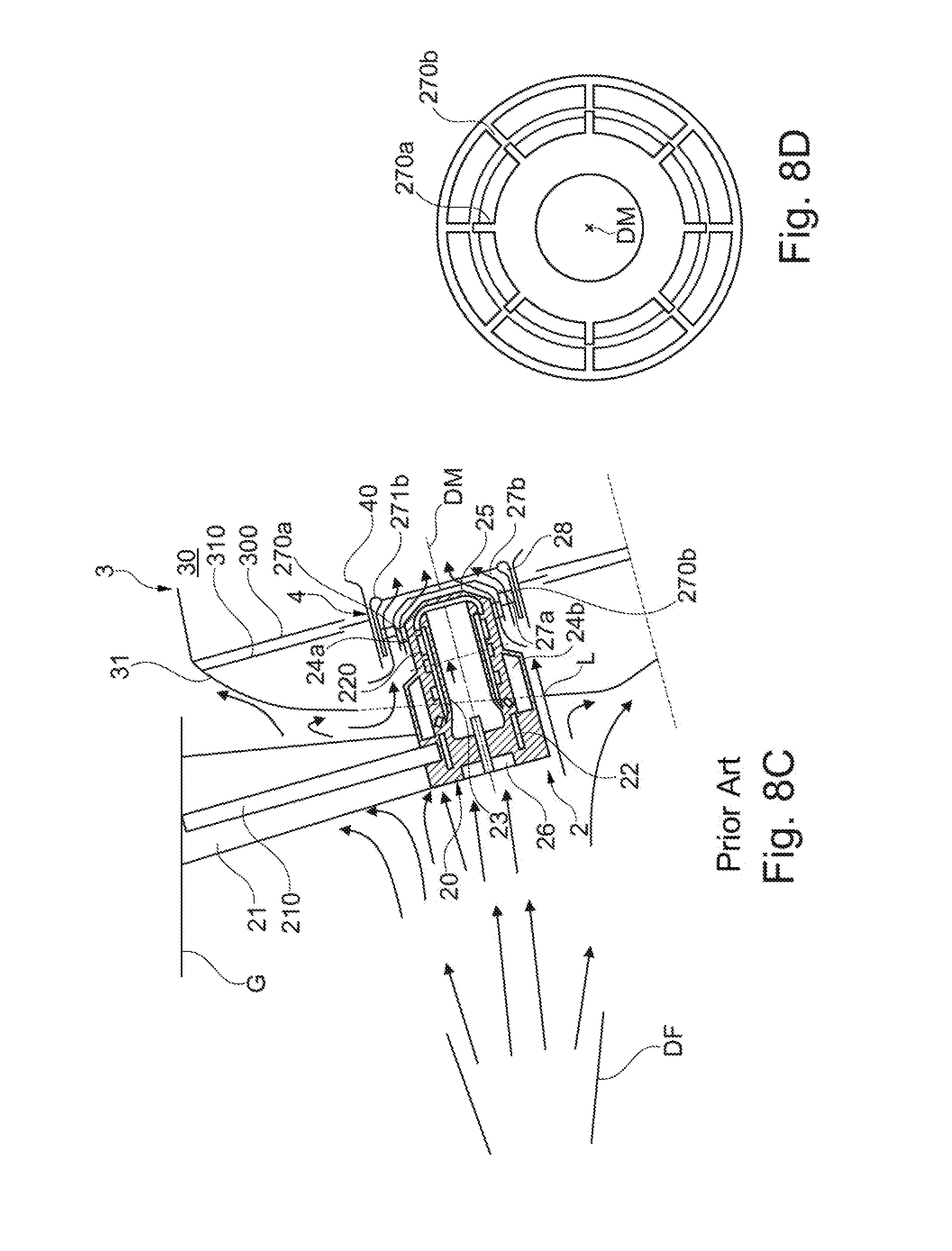
[0035] FIG. 8C shows, in a cross-sectional view, the basic structure of a nozzle according to the state of the art and the surrounding components of the engine in the installed state of the nozzle;
[0036] FIG. 8D shows a back view of a nozzle exit opening, also illustrating swirling elements that are provided in radially outwardly located air guiding channels of the nozzle.
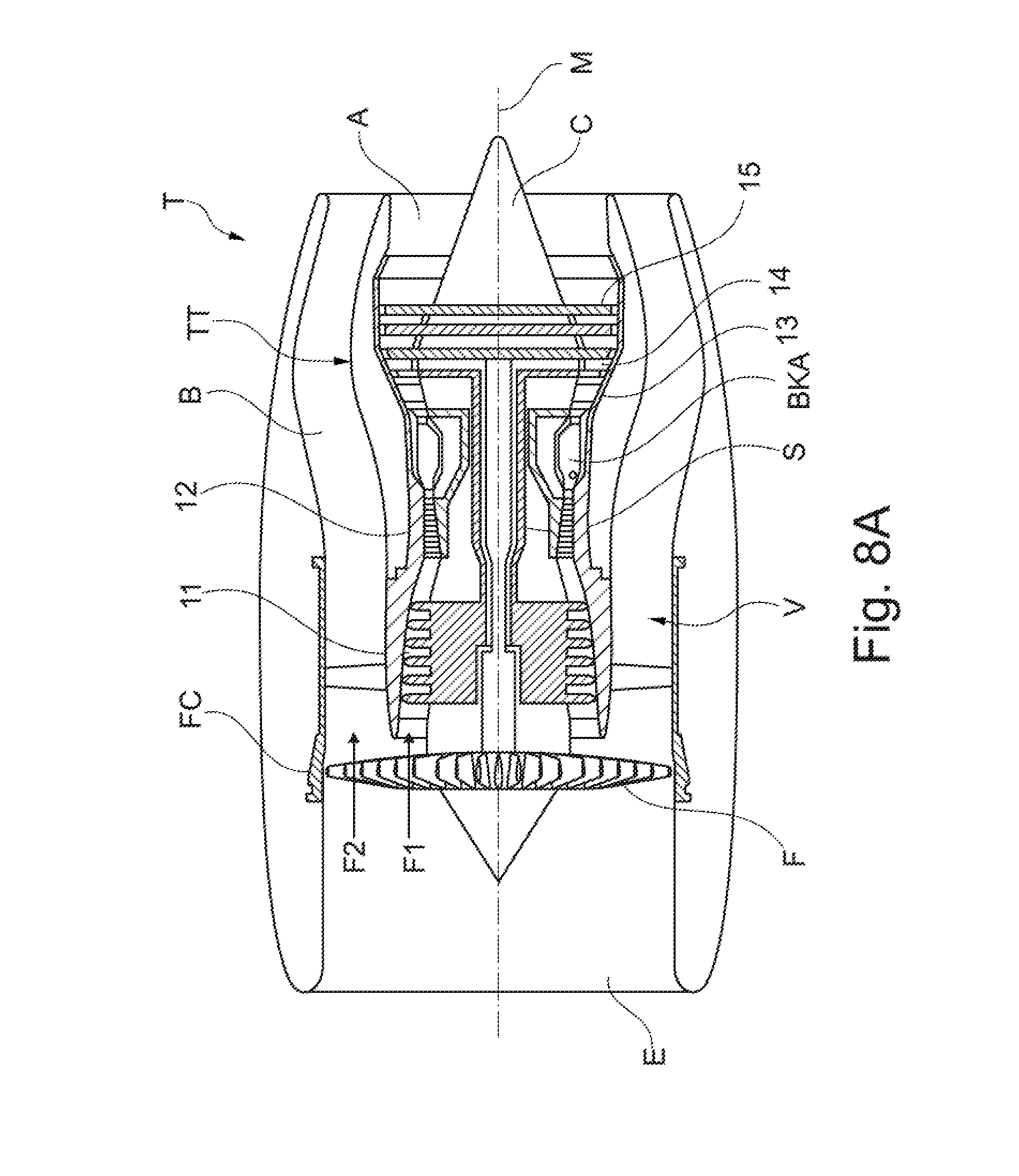
[0037] FIG. 8A schematically illustrates, in a sectional view, a (turbofan) engine T in which the individual engine components are arranged in succession along a rotational axis or central axis M and the engine T is embodied as a turbofan engine. By means of a fan F, air is suctioned in along an entry direction at an inlet or an intake E of the engine T. This fan F, which is arranged inside a fan housing FC, is driven via a rotor shaft S that is set into rotation by a turbine TT of the engine T. Here, the turbine TT connects to a compressor V, which for example has a low-pressure compressor 11 and a high-pressure compressor 12, and where necessary also a medium-pressure compressor. The fan F supplies air to the compressor V in a primary air flow F1, on the one hand, and, on the other, to a secondary flow channel or bypass channel B in a secondary air flow F2 for creating a thrust. Here, the bypass channel B extends about a core engine that comprises the compressor V and the turbine TT, and also comprises a primary flow channel for the air that is supplied to the core engine by the fan F.
[0038] The air that is conveyed via the compressor V into the primary flow channel is transported into the combustion chamber section BKA of the core engine where the driving power for driving the turbine TT is generated. For this purpose, the turbine TT has a high-pressure turbine 13, a medium-pressure turbine 14, and a low-pressure turbine 15. The turbine TT drives the rotor shaft S and thus the fan F by means of the energy that is released during combustion in order to generate the necessary thrust by means of the air that is conveyed into the bypass channel B. The air from the bypass channel B as well as the exhaust gases from the primary flow channel of the core engine are discharged via an outlet A at the end of the engine T. Here, the outlet A usually has a thrust nozzle with a centrally arranged outlet cone C.
[0039] FIG. 8B shows a longitudinal section through the combustion chamber section BKA of the engine T. Here, in particular an (annular) combustion chamber 3 of the engine T can be seen. A nozzle assembly group is provided for injecting fuel or an air-fuel-mixture into a combustion space 30 of the combustion chamber 3. It comprises a combustion chamber ring R along which multiple (fuel/injection) nozzles 2 are arranged along a circular line about the central axis M. Here, the nozzle exit openings of the respective nozzles 2 that are positioned inside the combustion chamber 3 are provided at the combustion chamber ring R. Here, each nozzle 2 comprises a flange by means of which a nozzle 2 is screwed to an outer housing G of the combustion chamber 3.
[0040] FIG. 8C now shows a cross-sectional view of the basic structure of a nozzle 2 as well as the surrounding components of the engine T in the installed state of the nozzle 2. Here, the nozzle 2 is part of a combustion chamber system of the engine T. The nozzle 2 is located downstream of a diffuser DF and during mounting is inserted through an access hole L through a combustion chamber head 31, through a heat shield 300 and a head plate 310 of the combustion chamber 3 up to the combustion space 30 of the combustion chamber 3, so that a nozzle exit opening formed at a nozzle main body 20 reaches all the way to the combustion space 30. The nozzle 2 further comprises a nozzle neck 21 which substantially extends radially with respect to the central axis M and inside of which a fuel supply 210 conveying fuel to the nozzle main body 20 is accommodated. Further formed at the nozzle main body 20 are a fuel chamber 22, fuel passages 220, heat shields 23 as well as air chambers for insulation 23a and 23b.
[0041] In addition, the nozzle main body 20 forms a (first) inner air channel 26 extending centrally along a nozzle longitudinal axis DM and, positioned radially further outside with respect to the same, a (second and third) outer air guiding channel 27a and 27b. These air guiding channels 26, 27a and 27b extend in the direction of the nozzle exit opening of the nozzle 2.
[0042] Further, also at least one fuel guiding channel 26 is formed at the nozzle main body 20. This fuel guiding channel 25 is located between the first inner air channel 26 and the second outer air channel 27a. The end of the fuel guiding channel 25, via which fuel flows out in the direction of the air from the first inner air channel 26 during operation of the nozzle 2, is located--with respect to the nozzle longitudinal axis DM and in the direction of the nozzle exit opening--in front of the end of the second air channel 27a from which air from the second, outer air channel 27a flows out in the direction of a mixture of air from the first, inner air channel 26 and fuel from the fuel guiding channel 25.
[0043] Swirling elements 270a, 270b for swirling the air supplied through the air guiding channels 27a and 27b are provided in the outer air guiding channels 27a and 27b. Further, the nozzle main body 20 also comprises an outer, radially inwardly oriented air guide element 271b at the end of the third outer air channel 27b. In the nozzle 2, which may e.g. be a pressure-assisted injection nozzle, the ends of the second and third radially outwardly located air guiding channels 27a and 27b follow--with respect to the nozzle longitudinal axis DM and in the direction of the nozzle exit opening--the end of the fuel guiding channel 25 from which fuel is supplied to the air from the first inner centrally extending air channel 26 during operation of the engine T, according to FIG. 8C. Air that is swirled by means of the swirling elements 270a, 270b is transported to the nozzle exit opening form these second and third air guiding channels 27a and 27b. As is shown in the back view of FIG. 8D with a view of the nozzle exit opening along the nozzle longitudinal axis DM, these swirling elements 270a, 270b are arranged inside the respective air channel 27a, 27b in a circumferentially distributed manner.
[0044] A sealing element 28 is also provided at the nozzle main body 20 at its circumference for sealing the nozzle 2 towards the combustion space 30. This sealing element 28 forms a counter-piece to a burner seal 4. This burner seal 4 is floatingly mounted between the heat shield 300 and the head plate 310 to compensate for radial and axial movements between the nozzle 2 and the combustion chamber 3 and to ensure reliable sealing in different operational states.
[0045] The burner seal 4 usually has a flow guiding element 40 towards the combustion space 30. In connection with the third outer air channel 27b at the nozzle 2, this flow guiding element 40 ensures a desired flow guidance of the fuel-air mixture that results from the nozzle 2, more precisely the swirled air from the air guiding channels 26, 27a and 27b, as well as the fuel guiding channel 25.
[0046] In an embodiment of a burner assembly group according to FIG. 8C as it is known in the state of the art, it is disadvantageous that the relative position of the burner seal 4, and in particular its flow guiding element 40, to the nozzle 2 can change during operation of the engine T in particular due to thermal extensions. Thus, an aerodynamic effect of the burner seal 4, and in particular the guidance of the fuel-air mixture across the flow guiding element 40, varies depending on the operational conditions.
[0047] This problem is remedied by the suggested solution, for which different embodiment variants are shown in the FIGS. 1 to 7.
[0048] Here, it is respectively provided that an extension 5 is provided at the air guide element 271b of the outermost, third air channel 27b, extending in the axial direction in order to guide the resulting fuel-air mixture in the direction of the combustion space 30. This extension 5, which may for example be formed or molded integrally at the nozzle main body 20, respectively projects beyond a bearing section 41 of the burner seal 4 at the combustion chamber side. The passage opening through which the nozzle 2 is positioned at the burner seal 4 is provided in this bearing section 41. By thus guiding the fuel-air mixture through the nozzle-side extension 5 in the direction of the combustion space 30 at the nozzle exit opening, the burner seal 4 does no longer take over an aerodynamic function. The burner seal 4 now only serves the purpose of sealing, and is correspondingly formed without a flow guiding element 40.
[0049] In particular in the nozzle 2 of FIG. 1 it is provided that the extension 5 of the shown embodiment variants that connects to the air guide element 271b has an outer diameter D2 that substantially corresponds to the outer diameter of the air guide element 271b and thus the nozzle 2 in the area of the burner seal 4. The extension 5 of the respective nozzle 2 is further designed in a tubular manner, and has an axial length l.sub.5 that is less than 3.5. times a height H of the swirling element 270b provided in the third air channel 27b.
[0050] Further, the axial expansion of extension 5 is respectively dimensioned in such a manner that other geometric conditions having proven to be advantageous are met. Thus, for guiding the air flowing out of the air channel 27b radially inwards, the air guide element 271b of the third air channel 27b defines an area with a minimal inner diameter D1 and thus a minimal cross-sectional surface of the nozzle exit opening through which the flow passes. A distance I of a reference point E1 at the location of this minimal inner diameter D1 to a further reference point E2 located in the axial direction and marking the end of the extension 5 is now dimensioned such that the following applies: H.ltoreq.I.ltoreq.3.5.ltoreq.H.
[0051] In particular the extension 5 of the nozzle 2 shown in FIG. 1 has two successive sections 50 and 51 with different inner diameters. Thus, initially a first section 50 with an inner diameter which remains constant along the nozzle longitudinal axis DM connects to the air guide element 271b. If is followed in the direction of the combustion space 30 by a considerably shorter, second section 51, where the inner diameter increases and accordingly the extension 5 widens.
[0052] While in the embodiment variant of FIG. 1 the extension 5 forms a ledge, and thus a recess at which the inner diameter is enlarged comparatively abruptly, in the transition from the air guide element 271b of the radially outermost, third air channel 27b, the embodiment variant of FIG. 2 provides an extension 5 with a smoother transition between an inner lateral surface of the air guide element 271b and an inner lateral surface of the extension 5. Here, the extension 5 is further continuously enlarged in a diffuser-like manner, so that an inner diameter of the extension 5 is continuously enlarged in the axial direction, and the inner lateral surface of the extension 5 extends radially outwards with respect to the nozzle longitudinal axis DM.
[0053] In contrast, in the variants of FIGS. 3 and 4, the transition between the air guide element 271b and the extension 5 is realized through a ledge. However, in contrast to the variants of FIGS. 1 and 2, here the downstream (end-side) section 51 is embodied so as to taper off towards the trailing edge.
[0054] In the variant shown in FIG. 5, the extension 5 has a slightly concave inner curvature for a smoother transition between the air guide element 271b and the extension 5. Here, the lateral surfaces of the air guide element 271b and the extension 5 transition into each other without steps. Thus, a flow is guided along the air guide element 271b and the extension 5 along their inner lateral surface, which transitions without any edges. Further, a slightly convex inner curvature is provided at the downstream distal end of the extension 5.
[0055] In the embodiment variant of FIG. 6, the extension 5 is also designed in such a manner that the lateral surfaces of the air guide element 271b and the extension 5 transition into each other without any steps at a transition 52, and the extension 5 thus directly connects to the air guide element 271b of the radially outermost, third air channel 27b. Also in this case, the extension 5 is embodied in such a manner that the extension 5 widens continuously in the axial direction along the nozzle longitudinal axis DM all the way to a tapering trailing edge. Here, the inner lateral surface of the extension 5 is slightly concavely curved.
[0056] In contrast to the embodiment variant of FIG. 6, the embodiment variant of FIG. 7 provides a continuous, diffuser-like widening of the extension 5 directly connecting to the air guide element 271b through an inner lateral surface that extends in a linear manner and is oriented radially outwards at a constant angle to the nozzle longitudinal axis DM.
[0057] In the shown embodiment variants of FIGS. 1 to 7, the nozzle 2 is respectively axially extended at a radially outermost third air channel 27b downstream of an air guide element 271b. The axial extension 5 provided for this purpose is respectively formed in a tubular manner and has the same outer diameter D2 as the nozzle 2 in the area of the burner seal 4. Here, the inner contour of the extension 5 is respectively chosen in such a manner that a widening of the extension 5 occurs along the nozzle longitudinal axis DM in the direction of the combustion space 30 at least in one section. Through the embodiment of the extension 5 at the nozzle 2 at which the resulting fuel-air mixture is guided in the direction of the combustion space 30, an admissible axial displaceability of the burner seal 4 and the nozzle 2 relative to each other does not influence the guidance of the fuel-air mixture. This is in particular advantageous when it comes to avoiding interfering soot emissions. Further, here the burner seal 4 seal only has to be configured and embodied for ensuring the sealing effect. The integration of a flow guiding element 40 at the burner device 4 may be omitted.
PARTS LIST
[0058] 11 low-pressure compressor [0059] 12 high-pressure compressor [0060] 13 high-pressure turbine [0061] 14 medium-pressure turbine [0062] 15 low-pressure turbine [0063] 2 nozzle [0064] 20 nozzle main body [0065] 21 neck [0066] 210 fuel supply [0067] 22 fuel chamber [0068] 220 fuel passage [0069] 23 heat shield [0070] 24a, 24b air chamber [0071] 25 fuel guiding channel [0072] 26 first air channel [0073] 270a, 270b swirling element [0074] 271b air guide element [0075] 27a second air channel [0076] 27b third air channel [0077] 28 sealing element [0078] 3 combustion chamber [0079] 30 combustion space [0080] 300 heat shield [0081] 31 combustion chamber head [0082] 310 head plate [0083] 4 burner seal [0084] 40 flow guiding element [0085] 41 bearing section [0086] 5 extension [0087] 50, 51 section [0088] 52 transition [0089] A outlet [0090] B bypass channel [0091] BKA combustion chamber section [0092] C outlet cone [0093] D1, D2 diameter [0094] DF diffuser [0095] DM nozzle longitudinal axis [0096] E inlet/intake [0097] E1, E2 reference point/end area [0098] F fan [0099] F1, F2 fluid flow [0100] FC fan housing [0101] G outer housing [0102] H height [0103] L access hole [0104] I distance [0105] l.sub.5 length [0106] M central axis/rotational axis [0107] R combustion chamber ring [0108] S rotor shaft [0109] T (turbofan) engine [0110] TT turbine [0111] V compressor
* * * * *
D00000
D00001
D00002
D00003
D00004
D00005
D00006
D00007
D00008
D00009
XML
uspto.report is an independent third-party trademark research tool that is not affiliated, endorsed, or sponsored by the United States Patent and Trademark Office (USPTO) or any other governmental organization. The information provided by uspto.report is based on publicly available data at the time of writing and is intended for informational purposes only.
While we strive to provide accurate and up-to-date information, we do not guarantee the accuracy, completeness, reliability, or suitability of the information displayed on this site. The use of this site is at your own risk. Any reliance you place on such information is therefore strictly at your own risk.
All official trademark data, including owner information, should be verified by visiting the official USPTO website at www.uspto.gov. This site is not intended to replace professional legal advice and should not be used as a substitute for consulting with a legal professional who is knowledgeable about trademark law.