Sheet Conveying Apparatus And Image Forming Apparatus
Mori; Hideki ; et al.
U.S. patent application number 16/131565 was filed with the patent office on 2019-03-28 for sheet conveying apparatus and image forming apparatus. The applicant listed for this patent is CANON KABUSHIKI KAISHA. Invention is credited to Jiroh Itoh, Yoshiaki Kisara, Hideki Mori, Masanori Ozawa.
| Application Number | 20190092594 16/131565 |
| Document ID | / |
| Family ID | 65808698 |
| Filed Date | 2019-03-28 |


View All Diagrams
| United States Patent Application | 20190092594 |
| Kind Code | A1 |
| Mori; Hideki ; et al. | March 28, 2019 |
SHEET CONVEYING APPARATUS AND IMAGE FORMING APPARATUS
Abstract
Disclosed is a sheet conveying apparatus. The sheet conveying apparatus includes a conveying roller pair (58) for conveying a sheet, a registration roller pair (57) disposed downstream of the conveying roller pair (58) and a guide portion for guiding the sheet conveyed to the registration roller pair (57) by the conveying roller pair (58) such that the sheet is deflected. Further, the guide portion guides the sheet such that a number of deflection nodes changes according to stiffness of the sheet.
| Inventors: | Mori; Hideki; (Toride-shi, JP) ; Ozawa; Masanori; (Yokohama-shi, JP) ; Itoh; Jiroh; (Yokohama-shi, JP) ; Kisara; Yoshiaki; (Tokyo, JP) | ||||||||||
| Applicant: |
|
||||||||||
|---|---|---|---|---|---|---|---|---|---|---|---|
| Family ID: | 65808698 | ||||||||||
| Appl. No.: | 16/131565 | ||||||||||
| Filed: | September 14, 2018 |
| Current U.S. Class: | 1/1 |
| Current CPC Class: | B65H 9/006 20130101; B65H 2404/6111 20130101; B65H 9/18 20130101; B65H 5/36 20130101; B65H 2515/81 20130101; B65H 9/002 20130101; B65H 5/062 20130101; B65H 2801/06 20130101 |
| International Class: | B65H 9/18 20060101 B65H009/18; B65H 5/36 20060101 B65H005/36; B65H 5/06 20060101 B65H005/06; B65H 9/00 20060101 B65H009/00 |
Foreign Application Data
| Date | Code | Application Number |
|---|---|---|
| Sep 22, 2017 | JP | 2017-182156 |
Claims
1. A sheet conveying apparatus, comprising: a conveying roller pair configured to convey a sheet; a registration roller pair disposed downstream of the conveying roller pair, for correcting skew feeding of the sheet with a leading end of the sheet conveyed by the conveying roller pair abutting against the registration roller pair; and a guide portion configured to guide the sheet conveyed to the registration roller pair by the conveying roller pair such that the sheet is deflected, wherein the guide portion includes a movable guide that is movable from a first position where an abutting portion of the guide portion for abutting the sheet that is conveyed is located on one side of a nip line of the conveying roller pair to a second position where the abutting portion is located on the other side of the nip line.
2. The sheet conveying apparatus according to claim 1, wherein the movable guide is displaced from the first position to the second position when the movable guide is pressed by the sheet having a predetermined or higher stiffness that is conveyed by the conveying roller pair.
3. The sheet conveying apparatus according to claim 1, wherein the guide portion includes: a first movable guide configured to displace when the first movable guide is pressed by the sheet having a predetermined or higher stiffness that is conveyed by the conveying roller pair; and a second movable guide disposed downstream of the first movable guide.
4. The sheet conveying apparatus according to claim 3, wherein the first movable guide is movable from a first position where an abutting portion of the first movable guide for abutting against the sheet which is conveyed is located on one side of the nip line of the conveying roller pair to a second position where the abutting portion is located on the other side of the nip line when the first movable guide is pressed by the sheet having a predetermined or higher stiffness that is conveyed by the conveying roller pair.
5. The sheet conveying apparatus according to claim 3, wherein the first movable guide is movable from a first position where an abutting portion of the first movable guide for abutting the sheet which is conveyed is located on a side of the nip line of the conveying roller pair with respect to an extended plane of a guide surface of the second movable guide to a second position where the abutting portion is away from the nip line when the first movable guide is pressed by the sheet having a predetermined or higher stiffness that is conveyed by the conveying roller pair.
6. The sheet conveying apparatus according to claim 5, wherein the second movable guide is movable from a first position where an abutting portion of the second movable guide for abutting the sheet that is conveyed is located in a vicinity of a nip line of the registration roller pair to a second position where the abutting portion is away from the nip line when the second movable guide is pressed by the sheet having a predetermined or higher stiffness that is conveyed by the conveying roller pair.
7. The sheet conveying apparatus according to claim 3, wherein a guide surface of the second movable guide intersects with the nip line of the conveying roller pair.
8. The sheet conveying apparatus according to claim 3, wherein the registration roller pair includes: a first roller disposed on one side of a sheet conveying path; and a second roller disposed on the other side of the sheet conveying path, stiffness of the second roller being higher than that of the first roller, and wherein the second movable guide is disposed on the other side of the sheet conveying path and a fixed guide is disposed on the one side of the sheet conveying path, the fixed guide being opposed to the second movable guide.
9. An image forming apparatus, comprising: a sheet conveying apparatus; and an image forming portion configured to form an image on a sheet conveyed by the sheet conveying apparatus, wherein the sheet conveying apparatus includes: a conveying roller pair configured to convey the sheet; a registration roller pair disposed downstream of the conveying roller pair, for correcting skew feeding of the sheet with a leading end of the sheet conveyed by the conveying roller pair abutting against the registration roller pair; and a guide portion configured to guide the sheet conveyed to the registration roller pair by the conveying roller pair such that the sheet is deflected, wherein the guide portion includes a movable guide that is movable from a first position where an abutting portion of the guide portion for abutting the sheet that is conveyed is located on one side of a nip line of the conveying roller pair to a second position where the abutting portion is located on the other side of the nip line.
Description
BACKGROUND OF THE INVENTION
Field of the Invention
[0001] The present invention relates to a sheet conveying apparatus capable of correcting skew, i.e. inclination of a conveyed sheet relative to a conveyance direction and relates to an image forming apparatus including such sheet conveying apparatus.
Description of the Related Art
[0002] A sheet fed from a cassette or the like in which sheets are stacked may be skewed while being conveyed for various factors such as a tapered shape of the conveying roller and misalignment of the conveying roller with respect to the image forming portion or the transfer portion.
[0003] In particular, when picking up a sheet from a cassette or when separating a sheet from sheets so that a plurality of sheets are not conveyed at the same time, skew feeding is likely to occur for the sheet due to narrow width of the roller and insufficient support of the sheet during turning.
[0004] Therefore, in order to obtain a good output image, it is necessary to correct skew feeding of a sheet before the image is transferred to the sheet at the image forming portion. Further, it is more effective for the correction position to be closer to the image forming portion.
[0005] As a means for correcting the skew feeding of the sheet, it is common to correct the skew feeding by the sheet abutting against the nip portion of the registration roller pair to make deflection of the sheet. However, the abutting force against the roller nip portion changes due to the deflection of the sheet because of the difference in stiffness (rigidity) of the sheet. When the abutting force of the sheet against the roller nip portion is weak, the sheet does not abut against the registration roller pair. Conversely, when the abutting force is strong, there is a problem that the sheet penetrates the nip portion of the registration roller pair.
[0006] In order to solve the above problem, Japanese Patent Application Laid-Open No. H06-191686 proposes that the curvature of the deflection is changed by pushing up a different guide according to the level of the stiffness of the sheet, thereby appropriately setting the abutting force against the nip portion of the registration roller pair.
[0007] In addition, Japanese Patent Application Laid-Open No. 2003-72982 proposes that in order to make uniform contact with the nip portion of the registration roller pair, it is preferable to form an S-shaped deflection as seen in the cross section of the sheet to be conveyed.
[0008] Recently, such an apparatus has been miniaturized and when the S-shaped deflection is formed on the sheet in a narrow space, the curvature of deflection becomes small. Then, if a sheet having a high stiffness, for example, a thick sheet is conveyed so as to form an S-shaped deflection having a small curvature, the sheet may be deformed into a deflection shape, which is called "residual curl". Due to this, problems (including sheet jam and a disturbance of the printed image) may occur.
[0009] In addition, when the deflection amounts (feed amounts of the conveying roller) are the same, the force with which the deflection extends increases as the number of deflection nodes (the number of curved portions) increases. For example, in the case of the S-shaped deflection (number of nodes of 3), the conveying roller needs higher torque for conveying the sheet for making deflection than in the case of the C-shaped deflection (number of nodes of 2). For this reason, there is a concern that the apparatus becomes large, or the leading end of the sheet penetrates through the nip portion of the registration roller pair and the skew feeding remains.
SUMMARY OF THE INVENTION
[0010] A sheet conveying apparatus according to the present invention, comprising: [0011] a conveying roller pair configured to convey a sheet; [0012] a registration roller pair disposed downstream of the conveying roller pair, for correcting skew feeding of the sheet with a leading end of the sheet conveyed by the conveying roller pair abutting against the registration roller pair; and [0013] a guide portion configured to guide the sheet conveyed to the registration roller pair by the conveying roller pair such that the sheet is deflected, [0014] wherein the guide portion includes a movable guide that is movable from a first position where an abutting portion of the guide portion for abutting the sheet that is conveyed is located on one side of a nip line of the conveying roller pair to a second position where the abutting portion is located on the other side of the nip line.
[0015] Further features of the present invention will become apparent from the following description of exemplary embodiments with reference to the attached drawings.
BRIEF DESCRIPTION OF THE DRAWINGS
[0016] FIG. 1 is a cross-sectional view showing a schematic configuration of a printer which is an example of an image forming apparatus according to embodiments of the present invention.
[0017] FIG. 2 is a perspective view for explaining a configuration of a skew feeding correcting portion according to the first embodiment.
[0018] FIG. 3 is a cross-sectional view for explaining a configuration of a skew feeding correcting portion according to the first embodiment of the present invention.
[0019] FIG. 4 is a cross-sectional view for explaining a skew feeding correcting operation for a sheet having a low stiffness in a skew feeding correcting portion according to the first embodiment of the present invention.
[0020] FIG. 5 is a cross-sectional view for explaining a skew feeding correcting operation for a sheet having a high stiffness in a skew feeding correcting portion according to the first embodiment of the present invention.
[0021] FIG. 6 is a perspective view for explaining a configuration of a skew feeding correcting portion according to the second embodiment.
[0022] FIG. 7 is a cross-sectional view for explaining a configuration of a skew feeding correcting portion according to the second embodiment of the present invention.
[0023] FIG. 8 is a cross-sectional view for explaining a skew feeding correcting operation for a sheet having a low stiffness in a skew feeding correcting portion according to the second embodiment of the present invention.
[0024] FIG. 9 is a cross-sectional view for explaining a skew feeding correcting operation for a sheet having a high stiffness in a skew feeding correcting portion according to the second embodiment of the present invention.
[0025] FIG. 10 is a cross-sectional view for explaining a configuration of a skew feeding correcting portion according to the third embodiment of the present invention.
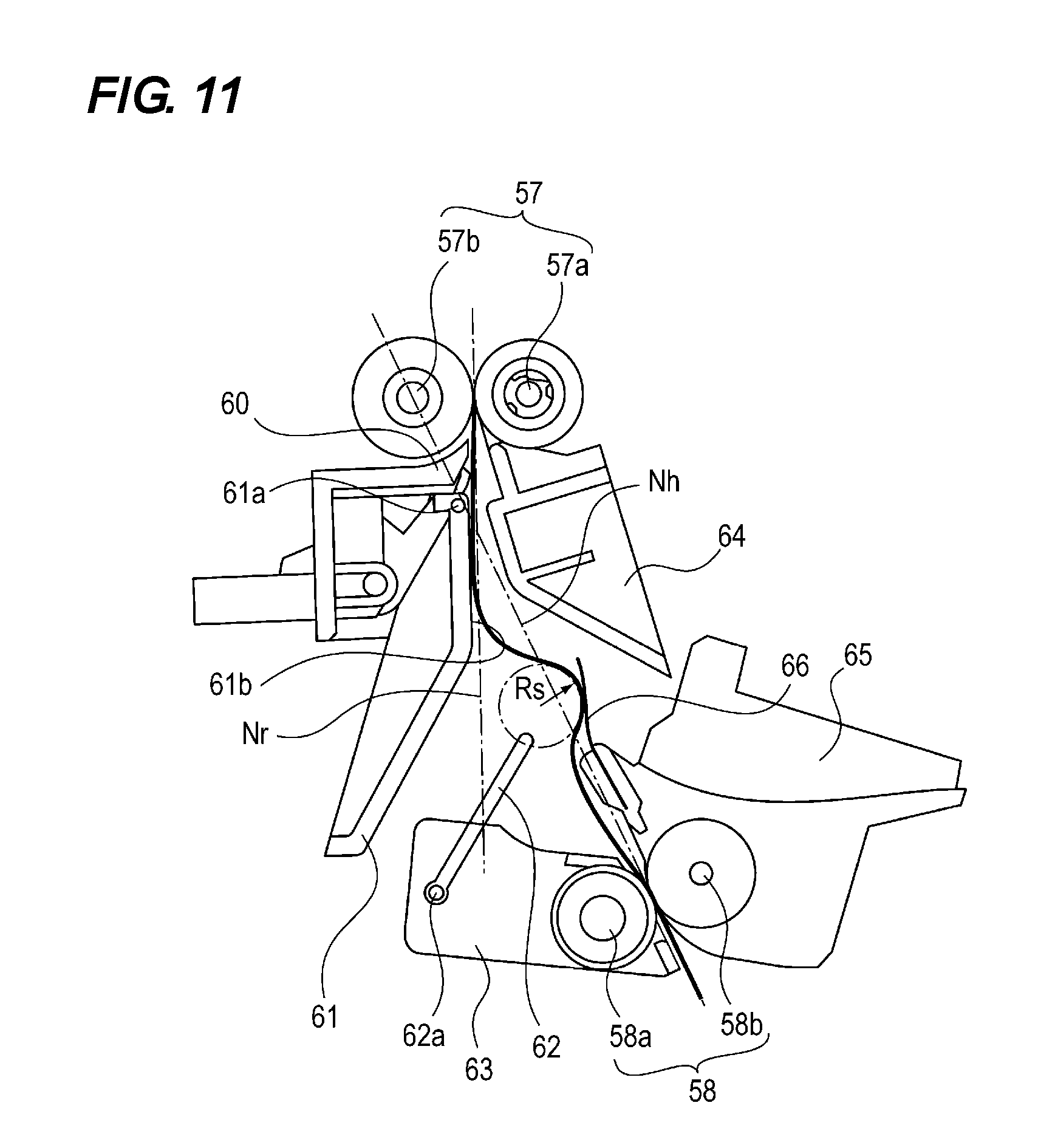
[0026] FIG. 11 is a cross-sectional view for explaining a skew feeding correcting operation for a sheet having a low stiffness in a skew feeding correcting portion according to the third embodiment of the present invention.
[0027] FIG. 12 is a cross-sectional view for explaining a skew feeding correcting operation for a sheet having a high stiffness in a skew feeding correcting portion according to the third embodiment of the present invention.
DESCRIPTION OF THE EMBODIMENTS
[0028] Next, a sheet conveying apparatus of the present invention will be described in detail with an image forming apparatus having this sheet conveying apparatus as an example.
[0029] {First Embodiment} <Overall Configuration of Image Forming Apparatus> FIG. 1 is a cross-sectional explanatory view of the image forming apparatus 100. As shown in this figure, at an upper portion of the image forming apparatus body 101, an image reading portion 130 for reading an original D placed on the platen glass 120a as an original placing platen by the automatic document feeding device 120. Under the image reading portion 130, there are provided the image forming portion 102, the sheet conveying apparatus 103 for conveying the sheet S to the image forming portion 102, and the manual feeding portion 104.
[0030] The image forming portion 102 is provided with the laser scanner unit 111, the photosensitive drum 112, the developing device 113, and the like.
[0031] Further, the sheet conveying apparatus 103 includes sheet storage cases 11 that accommodate the sheets S and are detachably attached to the image forming apparatus main body 101, the pickup rollers 21 that feed the sheets S stored in the sheet storage cases 11, and the like.
[0032] The manual feeding portion 104 includes the sheet tray 71 on which the sheets S are stacked and which is provided on a side surface of the image forming apparatus main body 101 which is a main body of the apparatus so as to be freely opened and closed, the feeding roller 51 for feeding the sheets S stacked on the sheet tray 71, and the like. When using the manual feeding portion 104, the sheet tray 71 is opened to protrude to a position where sheet feeding is possible, the user sets desired sheets on the protruding sheet tray 71, thereafter the sheets are fed. In FIG. 1, C denotes a control portion.
[0033] Next, the image forming operation of the image forming apparatus 100 having such a configuration will be described. When an image reading signal is outputted from the control portion C provided in the image forming apparatus main body 101 to the image reading portion 130, the image is read by the image reading portion 130. Thereafter, the laser scanner unit 111 irradiates the photosensitive drum 112 with laser light corresponding to this electric signal.
[0034] At this time, the photosensitive drum 112 has been charged in advance. An electrostatic latent image is formed by being irradiated with light, and then the electrostatic latent image is developed by the developing device 113, whereby a toner image is formed on the photosensitive drum 112. The toner image thus formed is primarily transferred to the outer periphery of the intermediate transfer belt 110, whereby a toner image is formed on the intermediate transfer belt 110.
[0035] When a feeding signal is outputted from the control portion C to the sheet conveying apparatus 103, the sheet S is fed out from the sheet storage case 11 as a sheet storing portion by the pickup roller 21. When the feed signal is outputted from the control portion C to the manual feeding portion 104, the sheet S is fed out by the feeding roller 51 from the sheet tray 71 which is a sheet storing portion. Thereafter, the skew feeding of the fed sheet S is corrected by the skew feeding correcting portion including the registration roller pair 57. Then, the sheet S is conveyed to the transfer portion including the intermediate transfer belt 110 and the secondary transfer roller 118 while being synchronized with the toner image on the intermediate transfer belt 110.
[0036] The toner image is transferred onto the sheet conveyed to the transfer portion, thereafter the sheet is conveyed to the fixing portion 114. The unfixed transferred image is permanently fixed on the sheet S by being heated and pressed by the fixing portion 114. The sheet on which the image has been fixed is discharged from the image forming apparatus main body 101 to the discharge tray 117 by the discharge roller 116.
[0037] <Sheet Conveying Apparatus> Next, the configuration of the sheet conveying apparatus that conveys the sheet to the image forming unit 102 will be described. Especially, the configuration of the skew feeding correcting portion for correcting the skew feeding of the conveyed sheet will be mainly described.
[0038] FIG. 2 is a perspective view of the skew feeding correcting portion, and FIG. 3 is a cross-sectional view of the skew feeding correcting portion. The conveying roller pair 58 including the driving roller 58a and the driven roller 58b is disposed on the sheet conveying path. The conveying roller pair 57 including the driving roller 57a and the driven roller 57b is disposed downstream in the sheet conveying direction (hereinafter referred to as "downstream") of the conveying roller pair 58. The fed sheet is conveyed to the registration roller pair 57, which is a second roller pair by the conveying roller pair 58, which is a first conveying roller pair. The leading end of the sheet is brought into contact with the nip portion of the registration roller pair 57 in the halt state with a predetermined pressing force thereby correcting the skew feeding of the sheet.
[0039] The first fixed guide 63 is provided on one side of the sheet conveying path between the conveying roller pair 58 and the registration roller pair 57. The first fixed guide 63 has a portion that curves so as to be separated from the nip line Nh of the conveying roller pair 58 downstream of the conveying roller pair 58 and that thereafter guides the sheet toward the nip portion of the registration roller pair 57.
[0040] The second fixed guide 64 is disposed on the side of the driving roller 57a and upstream in the sheet conveying direction (hereinafter referred to as "upstream") of the registration roller pair 57. The third fixed guide 65 is disposed on the side of the driven roller 58b of the conveying roller pair 58.
[0041] The movable guide 62 for guiding the sheet fed by the conveying roller pair 58 is attached to the first fixed guide 63 so as to be rotatable in the direction of the arrow A in FIG. 3. The movable guide 62 is disposed in the vicinity of the downstream side of the conveying roller pair 58. The movable guide 62 is usually urged by an urging member such as a spring (not shown) so as to be in a state indicated by a solid line in FIG. 3, and when pressed by the conveyed sheet, the movable guide 62 can be displaced to the state shown by the broken line in FIG. 3 resisting the urging force of the urging member.
[0042] When the movable guide 62 is in the first position shown by the solid line in FIG. 3, the guide portion 62b (abutting portion) which abuts against the sheet to be conveyed and guides the sheet is placed on the side of the third fixed guide 65 with respect to the nip line Nh. When the movable guide 62 is in the second position shown by the broken line in FIG. 3, the guide portion 62b is placed on the side of the first fixed guide 63 with respect to the nip line Nh. Namely, the movable guide 62 can be displaced from the first position where the guide portion 62b to abut against the conveyed sheet is positioned on one side of the nip line Nh to the second position where the guide portion 62b is positioned on the other side of the nip line Nh when the movable guide 62 is pressed with a pressing force which is equal to or stronger than a predetermined value by the sheet conveyed by the conveying roller pair 58.
[0043] Further, the movable guide 62 is so configured that when the movable guide 62 is in the first position, the angle 0 formed between the guide surface of the movable guide 62 and the nip line Nh of the conveying roller pair 58 is 45.degree. or less. As a result, the sheet that is conveyed by the conveyance roller pair 58 and that abuts against the movable guide 62 is smoothly conveyed along the guide surface.
[0044] <Sheet Conveyance States> Next, the conveyance states of the sheet conveyed by the conveying roller pair 58, guided by the movable guide 62, and to abut against the registration roller pair 57 will be explained in two cases including the case where the stiffness (strength of rigidity) of the sheet is low and the case where the stiffness (strength of the stiffness) of the sheet is high.
[0045] (Case Where A Sheet Whose Stiffness Is Lower Than A Predetermined Value) The skew feeding correcting operation in the case where the stiffness of the sheet S is lower than a predetermined value (for example, in the case of a thin paper having basis weight of 64 g/m.sup.2) will be described with reference to FIG. 4.
[0046] Since the stiffness of the sheet S fed by the conveying roller pair 58 is low, even if the sheet S abuts against the movable guide 62, the sheet S does not overcome the urging force of the urging member of the movable guide 62. Therefore, the movable guide 62 is maintained in the first position and the sheet is guided along the movable guide 62 to the second fixed guide 64. Further, as is clear from FIG. 3, the extended line of the guide surface of the second fixed guide 64 intersects with the guide surface of the first fixed guide 63 along the nip line Nr of the registration roller pair 57. Therefore, after the sheet is guided to the first fixed guide 63 along the second fixed guide 64, the sheet is conveyed to the registration roller pair 57 in the halt state along the first fixed guide 63.
[0047] Even after the leading end of the sheet reaches the registration roller pair 57, the sheet S is fed by a predetermined length by the conveying roller pair 58. As a result, as shown in FIG. 4, the sheet S is bent from the nip portion of the conveying roller pair 58 toward the side of the third fixed guide 65 between the registration roller pair 57 and the conveying roller pair 58. Thereafter, the sheet S is further bent toward the side of the fixed guide 63. Then, the sheet S is further bent toward the nip portion of the registration roller pair 57. That is, the deflection of S-shape having three deflection nodes occurs.
[0048] As described above, when the number of deflection nodes increases, the force with which the deflection expands under the same deflection amounts (feed amounts of the conveying roller) becomes greater than when the number of nodes is smaller. Due to the deflection, the leading end of the sheet S is uniformly brought into contact with the registration roller pair 57 so that the correction of the skew feeding is surely performed.
[0049] (Case Where A Sheet Whose Stiffness Is Higher Than A Predetermined Value) Next, the skew feeding correcting operation in the case where the stiffness of the sheet S is higher than a predetermined value (for example, in the case of thick paper having a basis weight of 256 g/m.sup.2) will be described with reference to FIG. 5.
[0050] Since the sheet S fed from the conveying roller pair 58 has high stiffness, when the sheet S abuts against the movable guide 62 and presses down the movable guide 62, the sheet S overcomes the urging force of the urging member of the movable guide 62 to move the movable guide 62 toward the side of the second position. As a result, the sheet S is guided to the guide surface of the first fixed guide 63 along the nip line Nr of the registration roller pair 57, which intersects with the nip line Nh of the conveying roller pair 58. Thereafter, the sheet S is positioned along the guide surface of the first fixed guide 63 and reaches the registration roller pair 57 in the halt state.
[0051] Even after the leading end of the sheet reaches the registration roller pair 57, the sheet S is fed by the predetermined length by the conveying roller pair 58. At this time, the sheet S is bent so as to press down the movable guide 62 between the registration roller pair 57 and the conveying roller pair 58. Further, and as shown in FIG. 5, the sheet S is bent from the nip portion of the conveying roller pair 58 toward the side of the first fixed guide 63. Then, the sheet S is further bent along the curvature of the pressed down movable guide 62 and the first fixed guide 63 and is conveyed toward the nip portion of the registration roller pair 57. Namely, the deflection of C-shape having two deflection nodes occurs. Due to the deflection, the leading end of the sheet S is uniformly brought into contact with the registration roller pair 57 so that the skew feeding is corrected.
[0052] In the case of a sheet with high stiffness, the curvature radius of deflection of the sheet S increases from Rs (FIG. 4) to Rc (FIG. 5). As a result, even a sheet having a high stiffness does not undergo residual curl. In addition, when the deflection amounts (feed amounts of the conveying roller) are the same, the force with which the deflection extends becomes smaller as the number of deflection nodes decreases. Therefore, as compared with the S-shaped deflection (number of nodes 3), the torque of the conveying rollers for conveying the sheet for making deflection can be smaller in the C-shaped deflection(number of nodes 2). Therefore, it is possible to reduce the size of the driving device. Further, it is possible to prevent skew feeding caused by the leading end of the sheet passing through the nip portion of the registration roller pair 57.
[0053] As described above, by making the movable guide 62 move in accordance with the stiffness of the sheet and by guiding and conveying the sheet so as to generate a number of deflection nodes on the sheet, corresponding to the stiffness, skew feeding correcting can be properly performed irrespective of the stiffness of the sheet.
[0054] {Second Embodiment} Next, the second embodiment of the present invention will be described. In the first embodiment described above, only one movable guide is used, but in the present embodiment two movable guides are used. Since the basic configuration of the apparatus of the present embodiment is the same as that of the above-described embodiment, duplicate explanation will be omitted, and the configuration that is the characterizing feature of this embodiment will be described here. In addition, members having the same functions as those in the above-described embodiment are denoted by the same reference numerals.
[0055] (First Movable Guide) FIG. 6 is a perspective view of the skew feeding correcting portion and FIG. 7 is a cross-sectional view of the skew feeding correcting portion. The first fixed guide 63 is provided with the first movable guide 62 which is rotatable in the direction of the arrow A in FIG. 7 around a rotational shaft 62a positioned in the vicinity of the conveying roller pair 58. Namely, the first movable guide 62 can be displaced from the first position (indicated by the solid line in FIG. 7) where the guide portion 62b (abutting portion) to abut against the sheet conveyed by the conveying roller pair 58 is positioned on one side (namely, the driven roller 58b side) of the nip line Nh of conveying roller pair 58 the to the second position (indicated by the broken line in FIG. 7) where the guide portion 62b is positioned on the other side (namely, the driving roller 58a side) of the nip line Nh.
[0056] The first movable guide 62 is urged by an urging member such as a spring (not shown) and is normally at the first position. When the first movable guide 62 is pressed by the conveyed sheet, the first movable guide 62 can be displaced to the second position, resisting the urging force of the urging member.
[0057] (Second Movable Guide) The fourth fixed guide 60 is provided downstream of the first fixed guide 63, and in the vicinity of the upstream side of the registration roller pair 57. The fourth fixed guide 60 is provided with the second movable guide 61 that is rotatable in the direction of the arrow B in FIG. 7 about the rotational shaft 61a. The second movable guide 61 is movable from the first position (indicated by a solid line in FIG. 7) where the guide surface 61b (abutting portion) for abutting against the conveyed sheet is positioned in the vicinity of the nip line Nr of the registration roller pair 57 to the second position (indicated by a broken line in FIG. 7) where the guide surface 61b is away from the nip line when the second movable guide 61 is pressed by the sheet which is conveyed by the first conveying roller pair and which has a predetermined or higher stiffness. The second movable guide 61 is urged by an urging member such as a spring (not shown) and is normally at the first position. When the second movable guide 61 is pressed by the conveyed sheet, the second movable guide 61 can be displaced to the second position, resisting the urging force of the urging member.
[0058] Also, the third fixed guide 65 is disposed on the opposite side of the first movable guide 62, and the second fixed guide 64 is disposed on the opposite side of the second movable guide 61.
[0059] (Case Where A Sheet Whose Stiffness Is Lower Than A Predetermined Value) The skew feeding correcting operation of the sheet conveying apparatus with the above-described configuration in the case where the stiffness of the sheet S is lower than a predetermined value (for example, in the case of a thin paper having basis weight of 64 g/m.sup.2) will be described with reference to FIG. 8.
[0060] Since the stiffness of the sheet S conveyed by the conveying roller pair 58 is low, even if the sheet S abuts against the first movable guide 62, the sheet S does not overcome the urging force of the urging member of the first movable guide 62. Therefore, the first movable guide 62 is maintained in the first position and the sheet is guided along the first movable guide 62 to the second fixed guide 64. Further, the sheet is guided along the second fixed guide 64 to the second movable guide 61. Even if the sheet abuts against the second movable guide 61, the sheet does not overcome the urging force of the urging member of the second movable guide 61 since the stiffness is low. As a result, the second movable guide 61 is maintained at the first position. After being guided by this second movable guide 61, the sheet is conveyed to the registration roller pair 57 in the halt state along the fourth fixed guide 60.
[0061] Even after the leading end of the sheet reaches the registration roller pair 57, the sheet S is fed by a predetermined length by the conveying roller pair 58. As a result, the S-shaped deflection occurs on the sheet S between the registration roller pair 57 and the conveying roller pair 58 as in the first embodiment described above. Namely, as shown in FIG. 8, the sheet S is bent from the nip portion of the conveying roller pair 58 toward the side of the third fixed guide 65. Thereafter, the sheet S is bent toward the side of the second movable guide 61. Then, the sheet S is bent toward the nip portion of the registration roller pair 57.
[0062] Due to the S-shaped deflection having three deflection nodes, the leading end of the sheet S is uniformly brought into contact with the registration roller pair 57 so that the correction of the skew feeding is surely performed.
[0063] (Case Where A Sheet Whose Stiffness Is Higher Than A Predetermined Value) Next, the skew feeding correcting operation in the case where the stiffness of the sheet S is higher than a predetermined value (for example, in the case of thick paper having a basis weight of 256 g/m.sup.2) will be described with reference to FIG. 9.
[0064] The sheet S fed from the conveying roller pair 58 is conveyed while pressing the first movable guide 62. At this time, since the stiffness of the sheet is high, the sheet overcomes the urging force of the urging member of the first movable guide 62 and is guided to the second movable guide 61 while pressing down the movable guide 62 to the side of the second position. Since the sheet S has high stiffness, as in the case of the first movable guide 62, the sheet S overcomes the urging force of the urging member of the second movable guide 61 so that the sheet S is conveyed to the registration roller pair 57 in the halt state along the second movable guide 61 while pressing down the second movable guide 61 to the side of the second position.
[0065] Even after the leading end of the sheet reaches the registration roller pair 57, the sheet S is fed by a predetermined length by the conveying roller pair 58. As a result, the sheet S presses down the first movable guide 62 and the second movable guide 61 between the registration roller pair 57 and the conveying roller pair 58 so that the C-shaped deflection with two deflection nodes occurs on the sheet S. Due to this deflection, the leading end of the sheet S is uniformly brought into contact with the registration roller pair 57 so that the skew feeding is corrected.
[0066] As a result, the curvature radius Rc of deflection of the sheet S is larger than the curvature radius Rs (see FIG. 8) of the S-shaped deflection shown in FIG. 8. Consequently, even a sheet having high stiffness, which is easy to be deformed into a deflected shape and to undergo so-called residual curl is used, residual curl does not remain. In the first embodiment, only one movable guides is used, but in the present embodiment, the second movable guide 61 is additionally provided downstream of the first movable guide 62 such that both movable guides are displaced to the second position when the sheet having high stiffness is used so that the sheet can be deflected with a larger curvature radius than in the case of the first embodiment.
[0067] Also, as in the case of the first embodiment, the number of C-shaped deflection nodes is smaller than the number of S-shaped deflection nodes if both deflection amounts (feed amounts of the conveying roller) are the same. Therefore, even if a sheet having high stiffness is used, it is possible to prevent skew feeding caused by the leading end of the sheet passing through the nip portion of the registration roller pair 57 without increasing the sheet conveying torque of the conveying roller pair 58.
[0068] (Stiffness Of Registration Roller Pair) In this embodiment, the registration roller pair 57 has the driving roller 57a and the driven roller 57b, each of which is formed of an elastic body such as rubber. Further, the driving roller 57a and the driven roller 57b have different stiffness. More specifically, the driven roller (first roller) 57b disposed on one side of the sheet conveying path has larger stiffness than the driving roller (second roller) 57a disposed on the other side of the sheet conveying path. The second movable guide 61 is disposed on the one side, that is, on the side on which the driven roller 57b is disposed with respect to the sheet conveying path. The second fixed guide 64 opposed to the second movable guide 61 is disposed on the other side, that is, on the side where the driving roller 57a is disposed.
[0069] With the configuration described above, it is possible to configure the guide surface of the second fixed guide such that the leading end of the sheet does not directly touch the driving roller 57a. As a result, by the second fixed guide 64, it is possible to prevent the sheet from directly abutting against the driving roller 58a which has low stiffness. Thus, regardless of how the second movable guide 61 is displaced, the leading end of the sheet to be conveyed is first brought into contact with the driven roller 57b having high stiffness and is guided to the roller nip portion so that the driving roller 57a whose stiffness is made low in order to increase sheet conveyance property is protected.
[0070] {Third Embodiment} Next, the third embodiment of the present invention will be described. Since the basic configuration of the present embodiment is the same as that of the above-described embodiments, duplicate explanation will be omitted, and the configuration that is the characterizing feature of this embodiment will be described here. In addition, members having the same functions as those in the above-described embodiments are denoted by the same reference numerals.
[0071] FIG. 10 is a cross-sectional view of the skew feeding correcting portion. The configuration of the skew feeding correcting portion of the present embodiment will be described with reference to FIG. 10.
[0072] The present embodiment also has two movable guides between the conveying roller pair 58 and the registration roller pair 57. The first movable guide 62 that is rotatable in the direction of the arrow A is provided downstream of the conveying roller pair 58. The second movable guide 61 that is rotatable in the direction of the arrow B is provided downstream thereof.
[0073] The first movable guide 62 can be displaced from the first position indicated by the solid line in FIG. 10 to the second position indicated by the broken line in FIG. 10. The first position is a position where the leading end (abutting portion) of the guide portion 62 to abut against the conveyed sheet is located on the side of the nip line Nh of the conveying roller pair 58 with respect to the extended plane of the guide surface 61b of the second movable guide 61. The second position is a position where the first movable guide 61 is away from the nip line Nh when the first movable guide 61 is pressed by the sheet having a predetermined stiffness or higher, conveyed by the conveying roller pair 58.
[0074] The second movable guide 61 can be disposed from the first position (indicated by a solid line in FIG. 10) where the guide surface 61b (abutting portion) for abutting against the conveyed sheet is positioned in the vicinity of the nip line Nr of the registration roller pair 57 to the second position (indicated by a broken line in FIG. 10) where the guide surface 61b is away from the nip line Nr when the second movable guide 61 is pressed by the sheet which is conveyed by the conveying roller pair 58 and which has a predetermined or higher stiffness. Each of the movable guides is urged by an urging member (not shown), and is normally held at the first position. Further, in the present embodiment, as shown in FIG. 10, the flexible guide 66 is provided at a position opposed to the guide portion of the first movable guide 62 with the sheet conveying path interposed between the guide portion of the first movable guide 62 and the flexible guide 66 when the first movable guide 62 is in the first position. The flexible guide 66 is composed of a flexible sheet. When the flexible guide 66 is pressed by the sheet on which a loop formed by deflection grows, the flexible guide 66 guides the sheet while pushing the sheet back with elasticity.
[0075] (Case Where A Sheet Whose Stiffness Is Lower Than A Predetermined Value) The skew feeding correcting operation of the sheet conveying apparatus with the above-described configuration in the case where the stiffness of the sheet S is lower than a predetermined value (for example, in the case of a thin paper having basis weight of 64 g/m.sup.2) will be described with reference to FIG. 11.
[0076] The rotational tip (guide portion) of the first movable guide 62 is positioned between the nip line Nh of the conveying roller pair 58 and the nip line Nr of the registration roller pair 57. Thus, the leading end of the sheet S fed from the conveying roller pair 58 reaches the second movable guide 61 without contacting the first movable guide 62. The sheet S is conveyed while being guided by the second movable guide 61. Because of the low stiffness, the sheet S does not overcome the urging force of the urging member of the second movable guide 61. Therefore, the sheet S is guided to the registration roller pair 57 in the halt state along the guide surface of the second movable guide 61 that is maintained in the first position.
[0077] In the present embodiment, the guide surface 61b of the second movable guide is disposed so as to have such positional relationship that the guide surface 61b intersects with the nip line Nh of the conveying roller pair 58. As a result, when the leading end of the sheet is conveyed by the conveying roller pair 58 without being guided by the first movable guide, the leading end of the sheet reaches the guide surface 61b of the second movable guide.
[0078] Even after the leading end of the sheet reaches the registration roller pair 57, the sheet S is fed by a predetermined length by the conveying roller pair 58 so that the deflection grows until it comes into contact with the first movable guide 62. When the deflection further grows, the sheet S cannot overcome the urging force of the urging member of the first movable guide 62 because the stiffness of the sheet S is low so that the first movable guide 62 is kept to be maintained at the first position. Then, the sheet S is pushed back by the first movable guide 62, and the deflection on the upstream side grows toward the side opposite to the first movable guide 62.
[0079] The deflection of the sheet S which has grown toward the side opposite to the first movable guide 62 becomes in contact with the flexible guide 66 and further grows while elastically deforming the flexible guide 66. Finally, an S-shaped deflection occurs between the registration roller pair 57 and the conveying roller pair 58 as shown in FIG. 11.
[0080] Due to the S-shaped deflection having three deflection nodes of the sheet S, the leading end of the sheet S is uniformly brought into contact with the registration roller pair 57 so that the skew feeding is corrected.
[0081] (Case Where A Sheet Whose Stiffness Is Higher Than A Predetermined Value) Next, the skew feeding correcting operation in the case where the stiffness of the sheet S is higher than a predetermined value (for example, in the case of thick paper having a basis weight of 256 g/m.sup.2) will be described with reference to FIG. 12.
[0082] The leading end of the sheet S fed from the conveying rollers pair 58 reaches the second movable guide 61. Since the stiffness of the sheet S is high, the sheet S overcomes the urging force of the urging member of the second movable guide 61 and is guided to the registration roller pair 57 in the halt state along the second movable guide 61 while pressing down the second movable guide 61 to the side of the retracted position. Even after the leading end of the sheet reaches the registration roller pair 57, the sheet S is fed by a predetermined length by the conveying roller pair 58. Since the stiffness of the sheet S is high, the sheet S overcomes the urging force of the urging members of the first movable guide 62 and the second movable guide 61. As a result, the sheet S presses down the first movable guide 62 and the second movable guide 61 between the registration roller pair 57 and the conveying roller pair 58 so that C-shaped deflection occurs on the sheet S. Due to this C-shaped deflection, the leading end of the sheet S is uniformly brought into contact with the registration roller pair 57 so that the skew feeding is corrected.
[0083] Due to this, the curvature radius of deflection of the sheet S increases from Rs (FIG. 11) to Rc (FIG. 12). As a result, even a sheet having a high stiffness, which is easy to undergo residual curl does not undergo residual curl.
[0084] Also, as in the case of the above-described embodiments, the number of C-shaped deflection nodes is smaller than the number of S-shaped deflection nodes if both deflection amounts (feed amounts of the conveying roller) are the same. Therefore, even if a sheet having high stiffness is used, it is possible to prevent skew feeding caused by the leading end of the sheet passing through the nip portion of the registration roller pair 57 without increasing the sheet conveying torque of the conveying roller pair 58.
[0085] While the present invention has been described with reference to exemplary embodiments, it is to be understood that the invention is not limited to the disclosed exemplary embodiments. The scope of the following claims is to be accorded the broadest interpretation so as to encompass all such modifications and equivalent structures and functions.
[0086] This application claims the benefit of Japanese Patent Application No. 2017-182156, filed Sep. 22, 2017, which is hereby incorporated by reference herein in its entirety.
* * * * *
D00000
D00001
D00002
D00003
D00004
D00005
D00006
D00007
D00008
D00009
D00010
D00011
D00012

XML
uspto.report is an independent third-party trademark research tool that is not affiliated, endorsed, or sponsored by the United States Patent and Trademark Office (USPTO) or any other governmental organization. The information provided by uspto.report is based on publicly available data at the time of writing and is intended for informational purposes only.
While we strive to provide accurate and up-to-date information, we do not guarantee the accuracy, completeness, reliability, or suitability of the information displayed on this site. The use of this site is at your own risk. Any reliance you place on such information is therefore strictly at your own risk.
All official trademark data, including owner information, should be verified by visiting the official USPTO website at www.uspto.gov. This site is not intended to replace professional legal advice and should not be used as a substitute for consulting with a legal professional who is knowledgeable about trademark law.