Systems And Methods For Three-dimensional Extraction Of Target Particles Ferrofluids
KOSER; Hur
U.S. patent application number 16/113793 was filed with the patent office on 2019-03-28 for systems and methods for three-dimensional extraction of target particles ferrofluids. The applicant listed for this patent is ANCERA, INC.. Invention is credited to Hur KOSER.
| Application Number | 20190091699 16/113793 |
| Document ID | / |
| Family ID | 51537682 |
| Filed Date | 2019-03-28 |

| United States Patent Application | 20190091699 |
| Kind Code | A1 |
| KOSER; Hur | March 28, 2019 |
SYSTEMS AND METHODS FOR THREE-DIMENSIONAL EXTRACTION OF TARGET PARTICLES FERROFLUIDS
Abstract
Systems, methods and devices are presented for extracting target particles within a ferrofluid medium. In some embodiments, a fluidic channel receives a flow of a mix of one or more types of target particles, where at least one magnetic field source is configured to react with the flow such that a force (indirect or direct) is placed on the particles of the mix, across the width and/or the height of the fluidic channel. An extraction opening placed on one wall is provided and configured to extract at least one type of target particle.
| Inventors: | KOSER; Hur; (Branford, CT) | ||||||||||
| Applicant: |
|
||||||||||
|---|---|---|---|---|---|---|---|---|---|---|---|
| Family ID: | 51537682 | ||||||||||
| Appl. No.: | 16/113793 | ||||||||||
| Filed: | August 27, 2018 |
Related U.S. Patent Documents
| Application Number | Filing Date | Patent Number | ||
|---|---|---|---|---|
| 14777504 | Sep 15, 2015 | |||
| PCT/US2014/028705 | Mar 14, 2014 | |||
| 16113793 | ||||
| 61794607 | Mar 15, 2013 | |||
| Current U.S. Class: | 1/1 |
| Current CPC Class: | B01L 2200/0668 20130101; B01L 2400/043 20130101; B03C 1/0332 20130101; B01L 3/502761 20130101; B03C 2201/18 20130101; B01L 3/50273 20130101; B03C 1/288 20130101; B03C 1/0335 20130101; B03C 2201/26 20130101 |
| International Class: | B03C 1/28 20060101 B03C001/28; B03C 1/033 20060101 B03C001/033; B01L 3/00 20060101 B01L003/00 |
Claims
1. A method for extracting particles within a ferrofluid medium, the method comprising: flowing a mix comprising a ferrofluid medium containing one or more types of target particles through at least one microfluidic channel, the at least one channel having: a first inlet portion for receiving the flow and a second portion spaced downstream from the first portion, a first side spaced away from a second side and comprising a width of the channel, and a third side spaced away from a fourth side and comprising a height of the channel, wherein the mix flows through the channel in a first direction from the first portion to the second portion; applying a magnetic field adjacent at least one of the sides of the channel, the magnetic field configured to concentrate at least one type of target particle contained in the mix within a width region, the width region comprising a portion of the width, and a height region, the height region comprising a portion of the height located at or adjacent to the third side, such that the at least one type of target particles from the flow are concentrated within the width region and the height region, creating a concentrated flow of target particles of the at least one type; and extracting the concentrated flow of target particles via an extraction opening arranged on the third side at or near the second portion, wherein the concentrated flow of target particles from the extraction opening includes an exit velocity.
2. The method of claim 1, wherein concentrating comprises at least one of separating, focusing and concentrating.
3. The method of claim 1, wherein a type of particles corresponds to at least one of a size, shape, mass, and charge of one or more particles.
4. The method of claim 1, wherein the first type of target particles comprises at least one of target moieties and target biological cells.
5. The method of claim 1, wherein applying a magnetic field includes applying a magnetic field through at least one of current-carrying electrodes and magnets.
6. The method of claim 1, further comprising adjusting the exit velocity of the concentrated flow of target particles by at least one of: configuring the magnetic field to effect forces on the flow affecting the exit velocity, configuring the size of the extraction opening to increase velocity, controlling the flow resistance from the extraction opening, and providing at least one of a pressure sink and a flow sink arranged downstream of the extraction opening.
7. A system for extracting particles within a ferrofluid medium, the system comprising: at least one microfluidic channel having a first inlet portion and a second portion spaced downstream from the first portion for receiving a flow of a mix comprising a ferrofluid medium containing one or more types of target particles, a first side spaced away from a second side and comprising a width of the fluidic channel, and a third side spaced away from a fourth side and comprising a height of the fluidic channel, wherein fluid flows through the fluidic channel in a first direction from the first end to the second end; magnetic field means arranged adjacent at least one of the sides of the fluidic channel, the magnetic field configured to focus at least one type of target particles contained in the ferrofluid medium flow within a width region, the width region comprising a portion of the width, and a height region, the height region comprising a portion of the height located at or adjacent to the third side, such that the target particles from the flow are concentrated within the width region and the height region creating a concentrated flow of particles; and an extraction opening arranged on the third side at or near the second end, the extraction opening configured to receive and direct the concentrated flow of target particles from the fluidic channel at an exit velocity.
8. The system of claim 7, wherein the target particles comprise at least one of target moieties and target biological cells.
9. The system of claim 7, wherein the magnetic field means comprises at least one of: one or more current-carrying electrodes and one or more magnets.
10. The system of claim 7, further comprising velocity adjustment means.
11. The system of claim 10, wherein the velocity adjustment means comprises flow resistance means.
12. The system of claim 10, wherein the velocity adjustment means comprises at least one of adjusting the magnetic field to effect forces on the flow affecting the exit velocity, the size of the extraction opening is configured to increase velocity, controlling the flow resistance from the extraction opening, and providing at least one of a pressure sink and a flow sink arranged downstream of the extraction opening.
Description
RELATED APPLICATIONS
[0001] This application claims benefit under 35 USC 119(e) of US provisional patent application No. 61/794,607, filed Mar. 15, 2013, and entitled, "3D Extraction in Biocompatible Ferrofluids," the entire disclosure of which is herein incorporated by reference in its entirety.
FIELD OF THE DISCLOSURE
[0002] The present disclosure relates to extraction in biocompatible ferrofluids and in particular, to systems and methods for separating a cells and/or other target particles suspended in a ferrofluid (e.g., a biocompatible ferrofluid).
BACKGROUND OF THE DISCLOSURE
[0003] As shown in FIG. 1, as the inventor's prior disclosures describe, i.e., WO2011/071912 and WO2012/057878, concentrating and extracting target moieties within microfluidics may be accomplished two-dimensionally, by placing a ferrofluid containing the target moieties within at least one micro/flow channel, and applying a magnetic field. The magnetic field is configured to effect an indirect force on the target moieties such that they are focused/separated into different streamlines of particles across the width of the flow channel. The streamlines that carry the target moieties are then extracted at the end of the channel via multiple outlets in the plane of the flow channel.
[0004] To that end, such approaches may be limited by the resolution with which the width of the streamlines carrying the focused moieties are aligned with a particular outlet channel for extracting those streamlines. Pulsations, or other non-steady pressure effects originating from, for example, pumps, geometry/elasticity of liquid channels/connectors, trapped air bubbles, partial blockages due to particles flowing through narrow geometries, and the like, can all add to time-dependent deviations in the ultimate trajectories of the target moieties.
SUMMARY OF THE DISCLOSURE
[0005] Embodiments of this disclosure correspond to further developments and applications of the inventor's previous series of disclosures, including, for example PCT publication no. WO2011/071912 and WO2012/057878, the noted disclosures of which are all herein incorporated by reference in their entireties.
[0006] Accordingly, in some embodiments, a method for extracting particles within a ferrofluid medium is provided. The method may comprise flowing a mix comprising a ferrofluid medium containing one or more types of target particles through at least one microfluidic channel. The at least one channel having a first inlet portion for receiving the flow and a second portion spaced downstream from the first portion, a first side spaced away from a second side and comprising to a width of the channel, and a third side spaced away from a fourth side and comprising a height of the channel, wherein the mix flows through the channel in a first direction from the first portion to the second portion. The method may also include applying a magnetic field adjacent at least one of the sides of the channel, the magnetic field configured to concentrate at least one type of target particle contained in the mix medium within a width region comprising a portion of the width and a height region comprising a portion of the height, the height region being located at or adjacent to the third side, such that the at least one first type of target particles from the flow are concentrated within the width region and the height region creating a concentrated flow of target particles. The method may also include extracting a flow of concentrated target particles of the first type from the mix via an extraction opening arranged on the third side at or near the second portion, where the flow of target particles of the first type from the extraction opening includes an exit velocity.
[0007] In some embodiments, a system for extracting particles within a ferrofluid medium is provided. Such embodiments may include at least one microfluidic channel having a first inlet portion and a second portion spaced downstream from the first portion for receiving a flow of a mix comprising a ferrofluid medium containing one or more types of target particle, a first side spaced away from a second side and comprising a width of the fluidic channel, and a third side spaced away from a fourth side and comprising a height of the fluidic channel. The fluid flows through the fluidic channel in a first direction from the first end to the second end. The system may also include magnetic field means arranged adjacent at least one of the sides of the fluidic channel, the magnetic field configured to focus at least one type of target particles contained in the ferrofluid medium flow within a width region comprising a portion of the width and a height region comprising a portion of the height. The height region being located at or adjacent to the third side, such that the target particles from the flow are concentrated within the width region and the height region creating a concentrated flow of particles. The system may further include an extraction opening arranged on the third side at or near the second end, the extraction opening configured to receive and direct the concentrated flow of target particles from the fluidic channel at an exit velocity.
[0008] Embodiments of the disclosure may further include one or more of the following features: [0009] the target particles comprise at least one of target moieties and target biological cells; [0010] the extraction opening having a shape comprising round, circular, square, a slit, rectangular, triangular and elliptical; [0011] the magnetic field means comprises at least one of one or more current-carrying electrodes and one or more magnets; [0012] velocity adjustment means; [0013] the velocity adjustment means comprises flow resistance means; [0014] the velocity adjustment means comprises at least one of: adjusting the magnetic field to effect forces on the flow affecting the exit velocity, the size of the extraction opening is configured to increase velocity, controlling the flow resistance from the extraction opening, and providing at least one of a pressure sink and a flow sink arranged downstream of the extraction opening.
[0015] The above-noted embodiments, as well as other embodiments, will become even more evident with reference to the following detailed description and associated drawing, a brief description of which is provided below.
BRIEF DESCRIPTION OF THE DRAWINGS
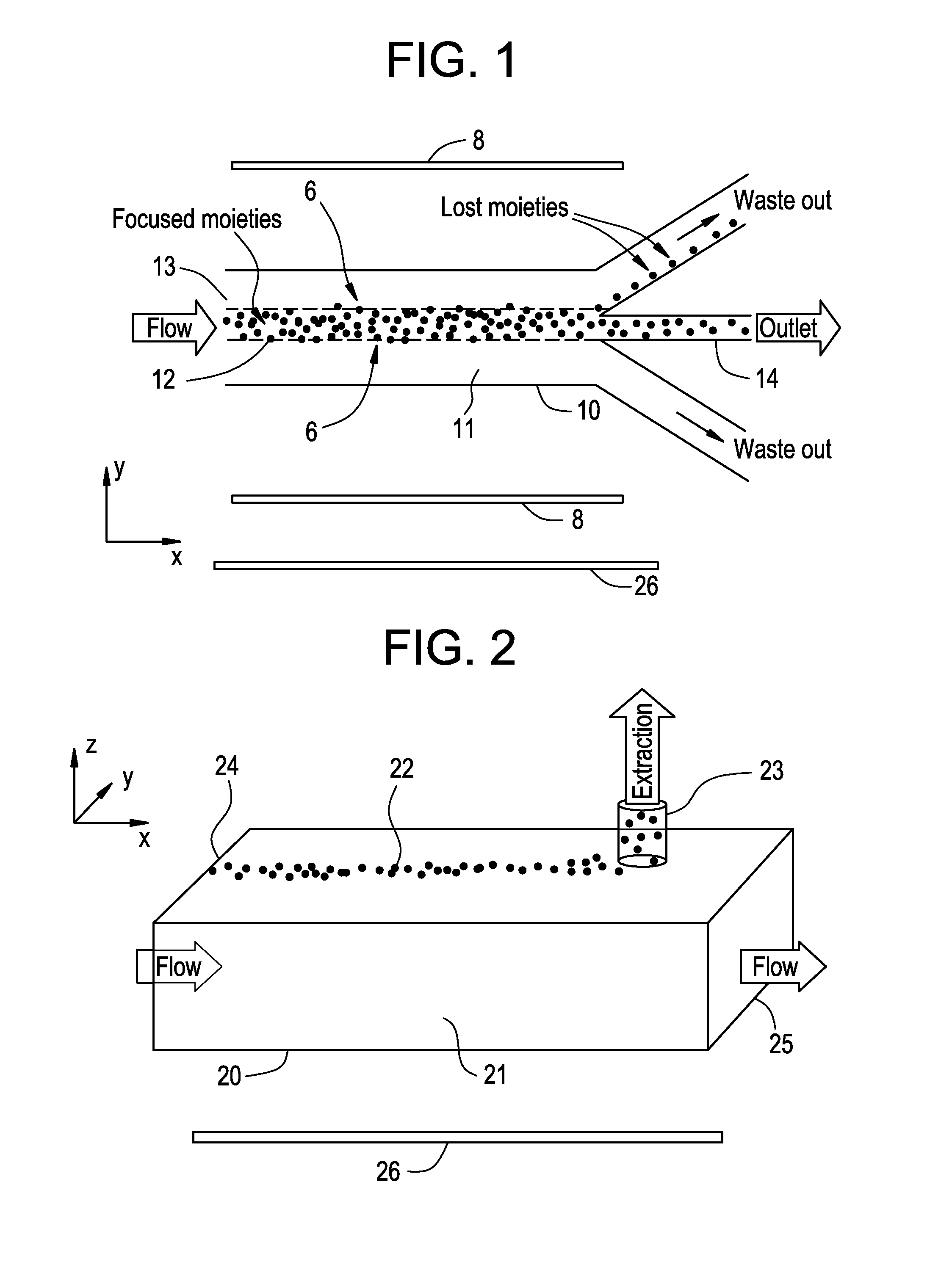
[0016] FIG. 1 is the illustrative structures of a microfluidic platform that performs concentration/enrichment of a target moiety.
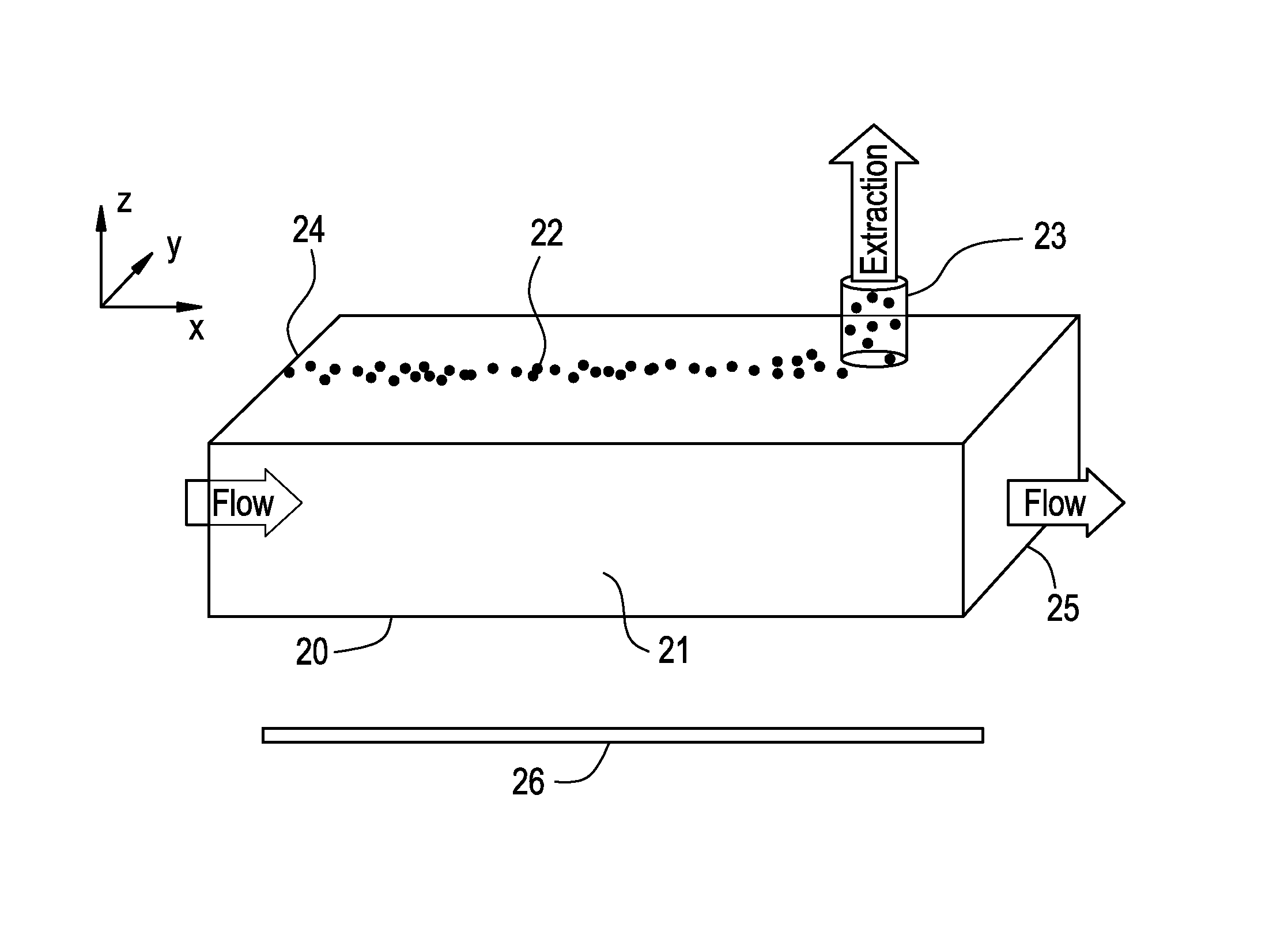
[0017] FIG. 2 is a schematic illustration of a system for extracting target particles from a ferrofluid medium according to some embodiments of the present disclosure.
[0018] FIG. 3 is a schematic illustrating a flow simulation depicting flow streamlines in close proximity to the exit opening of a microfluidic channel according to some embodiments of the present disclosure.
DETAILED DESCRIPTION OF SOME OF THE EMBODIMENTS
[0019] FIG. 1 shows a top view of a microfluidic channel 10 configured to perform concentration/enrichment of target particles 12 (e.g., moieties) from a ferrofluid flow 11 (e.g., comprising a mix of target particles and a ferrofluid medium). In such cases, the alignment of the focused target particles with an outlet 14 stream determines the concentration efficiency and loss. As is shown, magnetic field means 8 (which may comprise at least one of an electrode, a permanent magnet, and an electromagnet) applies a magnet field which is configured to focus target particles of the mix in a stream (e.g., see focusing boundaries 6). Misalignments due to device construction or pressure variations may limit the effective enrichment factor. While the magnetic field means are shown simply as two bars above/below the schematic of the channel, it is understood that the magnetic field means may be positioned anywhere relative to the flow which would affect the functionality of focusing/separating target particles (see, e.g., WO2011/071912 and WO2012/057878)
[0020] FIG. 2 illustrates concepts according to some embodiments, which may be referred to as "blow-hole" extraction. In such embodiments, for example, target particles 22 are suspended in a magnetic liquid medium 21 (e.g., a ferrofluid medium) forming a mix, where the target particles may comprise one or more types of particles (e.g., one more types of biological particles--e.g., cells, moieties, and the like), and flowed through one or more microfluidic channels 20 of an extraction and/or microfluidic system. Types of target particles also may be (and may be in addition to being a biological particle) based on at least one of size, shape, features, mass and charge. The fluidic channel(s) 20 may be provided for in a cartridge configured to be removable from a general system for each new particle extraction. Magnetic field applying means 26, which may comprise any one or more of electrodes and magnets, may be positioned adjacent at least one side of the fluidic channel, and are simply shown adjacent the channel in FIG. 2; however, it will be understood that the magnetic field means is positioned relative to the channel(s) to effect the separation functionality of at least some of the embodiments taught by this disclosure.
[0021] In some embodiments, the magnetic fields are configured to act upon the mix/ferrofluid 21 such that target particles 22 are concentrated, focused, or otherwise separated (these terms used interchangeably throughout), along a portion of the flow. For example, in some embodiments, a fluidic cartridge, having for example parallel microfluidic channels 20, is arranged adjacent (e.g., on top of) one or more current-carrying electrodes and/or magnets. Upon activation of the magnetic field, the target particles 22 become concentrated, for example, along a central portion of the fluid flow from an inlet 24 end/portion to an outlet end/portion 25 (e.g., an end/portion of the channel which is spaced apart from the inlet end), and, in some embodiments, the magnetic field also is configured to concentrate the target particles along one side of the fluidic channel.
[0022] For example, if the magnetic field means is placed below the cartridge, it may be configured to direct the target particles in a concentrated stream within the center of the fluid flow, and may also (or in place of) concentrate the target particles along the "ceiling" (e.g., a side) of the channel (relative to the "floor" of the channel, in, for example, a vertical direction).
[0023] Accordingly, in some embodiments, an extraction opening/orifice/hole 23 is arranged downstream from the inlet end 24 of the channel 20, on the "ceiling" side, from which the concentrated flow of target particles (e.g., the target particles themselves) may be extracted therefrom (FIG. 2). The velocity or speed of the flow of concentrated target particles from the extraction opening 23 may be adjusted either passively, by controlling flow resistance of the extraction orifice or main ferrofluid flow, and/or actively via the incorporation of a pressure of flow sink downstream of the extraction orifice (e.g., an outlet to the microfluidic channel). Likewise, the magnetic field may be configured to effect the velocity, in some embodiments, of particles being extracted via the extraction opening. The extraction opening 23 is downstream of the inlet 24, in some embodiments, sufficiently far from the inlet 24 that the particles 22 being manipulated have had time to be pushed up to the channel ceiling and concentrated into a tight stream. Hence, the distance configured is based on at least one of flow rate, magnetic field intensity and size of the particles being manipulated. In some embodiments, the distances may be in range of between about 0.5-5 cm. As for the size of the extraction opening size, in some embodiments, the size may be between about 100 to about 1000 .mu.m.
[0024] In some embodiment, the focusing resolution achieved in the plane of the fluidic channel 10 (e.g., the x-y plane in FIGS. 1 and 2) may be supplemented by the localization field/power achieved in the normal direction (i.e., the z-axis in FIGS. 1 and 2). Since target particles 12 (e.g., cells and/or other microscale moieties) suspended in a ferrofluid 11 may be directed towards a wall of the fluidic channel 10 (e.g., externally applied magnetic fields via the magnetic field means), the average distance from the specific wall and the target particles may effectively become their corresponding average radii as the particles interact (e.g., roll) on the wall--and thus, become flow streamlines of such particles. Accordingly, in some embodiments, the exit flow rate through the extraction channel (relative to the main channel's flow rate) may be engineered to be sufficient enough to attract flow streamlines having distances from the wall slightly larger than the average radius of the focused target particles. According to such embodiments, these focused target particles may then be extracted through the extraction orifice. In some embodiments, the wall height is configured to be greater than the largest particle within the ferrofluid mix, and may be, for example, between about 10-1000 .mu.m.
[0025] For example, FIG. 3 shows a flow simulation depicting flow streamlines for target particle 31 extraction which are in close proximity to the extraction opening 32. In such embodiments, and as an example, target particles 31 (e.g., cells of about 2 microns in diameter) are pushed via at least one of the ferrofluid flow and magnetic field, to within 1 micron of the upper channel (i.e., ceiling). Conservatively, the extraction orifice/geometry may be configured to yield a predetermined extraction margin, which in some embodiments may be near or equal to 100%, less than 100% or between about 75% and 100%, or a majority. Thus in a nearly 100% margin configuration, streamlines that are about 2 microns below the channel ceiling, and (in some embodiments) co-linear with the location of the extraction opening 32, may be attracted to the extraction opening 32 for extraction (FIG. 3). In another example, for a flow channel 30 that is 50 microns deep, which may yield a boost of about 25 times (50/2) the concentration factor already achieved along the x-y plane. Hence, in some embodiments, concentration factors on the order of between about 250-500 may be realized.
[0026] Any and all references to publications or other documents, including but not limited to, patents, patent applications, articles, webpages, books, etc., presented in the present application, are herein incorporated by reference in their entirety.
[0027] Example embodiments of the devices, systems and methods have been described herein. As noted elsewhere, these embodiments have been described for illustrative purposes only and are not limiting. Other embodiments are possible and are covered by the disclosure, which will be apparent from the teachings contained herein. Thus, the breadth and scope of the disclosure should not be limited by any of the above-described embodiments but should be defined only in accordance with claims supported by the present disclosure and their equivalents. Moreover, embodiments of the subject disclosure may include methods, systems and devices which may further include any and all elements from any other disclosed methods, systems, and devices, including any and all elements corresponding to target particle separation, focusing/concentration. In other words, elements from one or another disclosed embodiments may be interchangeable with elements from other disclosed embodiments. In addition, one or more features/elements of disclosed embodiments may be removed and still result in patentable subject matter (and thus, resulting in yet more embodiments of the subject disclosure). Correspondingly, some embodiments of the present disclosure may be patentably distinct from one and/or another reference by specifically lacking one or more elements/features. In other words, claims to certain embodiments may contain negative limitation to specifically exclude one or more elements/features resulting in embodiments which are patentably distinct from the prior art which include such features/elements.
* * * * *
D00000
D00001
D00002
XML
uspto.report is an independent third-party trademark research tool that is not affiliated, endorsed, or sponsored by the United States Patent and Trademark Office (USPTO) or any other governmental organization. The information provided by uspto.report is based on publicly available data at the time of writing and is intended for informational purposes only.
While we strive to provide accurate and up-to-date information, we do not guarantee the accuracy, completeness, reliability, or suitability of the information displayed on this site. The use of this site is at your own risk. Any reliance you place on such information is therefore strictly at your own risk.
All official trademark data, including owner information, should be verified by visiting the official USPTO website at www.uspto.gov. This site is not intended to replace professional legal advice and should not be used as a substitute for consulting with a legal professional who is knowledgeable about trademark law.