Motion Correction Apparatus
Kitamura; Shiro ; et al.
U.S. patent application number 16/136027 was filed with the patent office on 2019-03-28 for motion correction apparatus. The applicant listed for this patent is Honda Motor Co., Ltd.. Invention is credited to Shigenori Hiruta, Shiro Kitamura, Daisuke Muramatsu, Shuji Nakayama.
| Application Number | 20190091513 16/136027 |
| Document ID | / |
| Family ID | 65808572 |
| Filed Date | 2019-03-28 |

| United States Patent Application | 20190091513 |
| Kind Code | A1 |
| Kitamura; Shiro ; et al. | March 28, 2019 |
MOTION CORRECTION APPARATUS
Abstract
A motion correction apparatus, including: a setting portion configured to set a target motion; a detecting unit configured to detect an actual motion of a user corresponding to the target motion; a motion correcting unit configured to correct user motion by applying an external stimuli to a body or a brain of the user; and an outputting unit configured to output control signals to the motion correcting unit based on an attainment level of the actual motion detected by the detecting unit to the target motion so that the actual motion approaches to the target motion, wherein the target motion includes a final target motion and a single or a plurality of intermediate target motion set in steps up to the final target motion.
| Inventors: | Kitamura; Shiro; (Wako-shi, JP) ; Muramatsu; Daisuke; (Tokyo, JP) ; Hiruta; Shigenori; (Wako-shi, JP) ; Nakayama; Shuji; (Tokyo, JP) | ||||||||||
| Applicant: |
|
||||||||||
|---|---|---|---|---|---|---|---|---|---|---|---|
| Family ID: | 65808572 | ||||||||||
| Appl. No.: | 16/136027 | ||||||||||
| Filed: | September 19, 2018 |
| Current U.S. Class: | 1/1 |
| Current CPC Class: | A63B 2213/004 20130101; A61B 5/1128 20130101; A63B 24/0087 20130101; A63B 2024/0012 20130101; A61N 1/0484 20130101; A63B 2220/89 20130101; G06K 9/00342 20130101; A61B 5/1122 20130101; A63B 2220/836 20130101; G06K 9/00536 20130101; G09B 19/0038 20130101; A61N 1/3603 20170801; A63B 2024/0093 20130101; A61B 5/0476 20130101; A63B 2220/807 20130101; A63B 69/3608 20130101; A63B 2230/105 20130101; A61B 5/6803 20130101; A63B 2220/40 20130101; A61N 1/0452 20130101; A61N 1/0492 20130101; A63B 69/3623 20130101; A63B 24/0006 20130101; A61B 2562/0219 20130101; A63B 2230/085 20130101; A61N 1/36003 20130101; A63B 2022/0092 20130101; A61N 1/0476 20130101; A63B 69/36 20130101 |
| International Class: | A63B 24/00 20060101 A63B024/00; A63B 69/36 20060101 A63B069/36 |
Foreign Application Data
| Date | Code | Application Number |
|---|---|---|
| Sep 26, 2017 | JP | 2017-185124 |
Claims
1. A motion correction apparatus, comprising: a detecting unit configured to detect an actual motion of a user corresponding to a target motion; a motion correcting unit configured to correct user motion by applying an external stimuli to a body or a brain of the user; and a processor and a memory, the processor configured to set a target motion, and the processor configured to output control signals to the motion correcting unit based on an attainment level of the actual motion detected by the detecting unit to the target motion so that the actual motion approaches to the target motion, wherein the target motion includes a final target motion and a single or a plurality of intermediate target motion set in steps up to the final target motion.
2. The motion correction apparatus according to claim 1, wherein the processor is configured to output control signals to the motion correcting unit based on the attainment level of the actual motion detected by the detecting unit to the intermediate target motion so that the actual motion approaches to the intermediate target motion, and configured to output, when the attainment level of the actual motion to the intermediate target motion is equal to or greater than a predetermined value, control signals to the motion correcting unit based on the attainment level of the actual motion detected by the detecting unit to the final target motion so that the actual motion approaches to the final target motion.
3. The motion correction apparatus according to claim 2, further comprising: a selecting unit configured to select one of a plurality of the final target motion in response to a command from the user, wherein the processor is configured to set the final target motion selected by the selecting unit, wherein the processor is configured to output the control signals to the motion correcting unit so that the actual motion detected by the detecting unit approaches to the final target motion.
4. The motion correction apparatus according to claim 1, wherein the motion correcting unit is further configured to be worn on the body of the user, and configured as an equipment having an electrode or an actuator, wherein the processor is configured to output control signals to the electrode or the actuator based on the attainment level of the actual motion to the target motion.
5. The motion correction apparatus according to claim 4, wherein the processor is configured to output electric control signals larger in proportion as the attainment level of the actual motion to the target motion is lower.
6. The motion correction apparatus according to claim 1, further comprising: a display configured to display the attainment level of the actual motion to the target motion.
7. The motion correction apparatus according to claim 1, wherein the processor is configured to set an initial target motion based on an initial attainment level of the actual motion detected by the detecting unit to the final target motion.
8. A motion correction method, comprising: setting a target motion; detecting an actual motion of a user corresponding to the target motion; and correcting user motion by applying an external stimuli to a body or a brain of the user based on an attainment level of the actual motion detected by the detecting unit to the target motion so that the actual motion approaches to the target motion, wherein the target motion includes a final target motion and a single or a plurality of intermediate target motion set in steps up to the final target motion.
9. A motion correction apparatus, comprising: a setting portion configured to set a target motion; a detecting unit configured to detect an actual motion of a user corresponding to the target motion; a motion correcting unit configured to correct user motion by applying an external stimuli to a body or a brain of the user; and an outputting unit configured to output control signals to the motion correcting unit based on an attainment level of the actual motion detected by the detecting unit to the target motion so that the actual motion approaches to the target motion, wherein the target motion includes a final target motion and a single or a plurality of intermediate target motion set in steps up to the final target motion.
10. The motion correction apparatus according to claim 9, wherein the outputting unit is further configured to output control signals to the motion correcting unit based on the attainment level of the actual motion detected by the detecting unit to the intermediate target motion so that the actual motion approaches to the intermediate target motion, and configured to output, when the attainment level of the actual motion to the intermediate target motion is equal to or greater than a predetermined value, control signals to the motion correcting unit based on the attainment level of the actual motion detected by the detecting unit to the final target motion so that the actual motion approaches to the final target motion.
11. The motion correction apparatus according to claim 10, further comprising: a selecting unit configured to select one of a plurality of the final target motion in response to a command from the user, wherein the setting portion is further configured to set the final target motion selected by the selecting unit, wherein the outputting unit is further configured to output the control signals to the motion correcting unit so that the actual motion detected by the detecting unit approaches to the final target motion set by the setting portion.
12. The motion correction apparatus according to claim 9, wherein the motion correcting unit is further configured to be worn on the body of the user, and configured as an equipment having an electrode or an actuator, wherein the outputting unit is further configured to output control signals to the electrode or the actuator based on the attainment level of the actual motion to the target motion.
13. The motion correction apparatus according to claim 12, wherein the outputting unit is further configured to output electric control signals larger in proportion as the attainment level of the actual motion to the target motion is lower.
14. The motion correction apparatus according to claim 9, further comprising: a display configured to display the attainment level of the actual motion to the target motion.
15. The motion correction apparatus according to claim 9, wherein the setting portion is further configured to set an initial target motion based on an initial attainment level of the actual motion detected by the detecting unit to the final target motion.
Description
CROSS-REFERENCE TO RELATED APPLICATION
[0001] This application is based upon and claims the benefit of priority from Japanese Patent Application No. 2017-185124 filed on Sep. 26, 2017, the content of which is incorporated herein by reference.
BACKGROUND OF THE INVENTION
Field of the Invention
[0002] This invention relates to a motion correction apparatus and a motion correction method for correcting user motion.
Description of the Related Art
[0003] Among conventional apparatuses of this type are known ones that compare actual user motion data with pre-stored standard motion data, generate data for motion correction based on result of the comparison, and output the generated data to a motion guidance unit. Such an apparatus is described in Japanese Unexamined Patent Publication No. 2010-246912 (JP2010-246912A), for example. The apparatus of JP2010-246912A responds to occurrence of a difference between standard motion data and actual motion data by outputting a vibration or sound signal to a device worn by the user and thereby informing the user that his or her actual motion was incorrect.
[0004] However, it is difficult to efficiently correct user motion with an apparatus like that of the aforesaid JP2010-246912A configured to inform the user of incorrect motions using vibration and/or sound.
SUMMARY OF THE INVENTION
[0005] An aspect of the present invention is a motion correction apparatus, including: a detecting unit configured to detect an actual motion of a user corresponding to a target motion; a motion correcting unit configured to correct user motion by applying an external stimuli to a body or a brain of the user; and a processor and a memory, the processor configured to set a target motion, and the processor configured to output control signals to the motion correcting unit based on an attainment level of the actual motion detected by the detecting unit to the target motion so that the actual motion approaches to the target motion. The target motion includes a final target motion and a single or a plurality of intermediate target motion set in steps up to the final target motion.
[0006] Another aspect of the present invention is a motion correction apparatus, including: a setting portion configured to set a target motion; a detecting unit configured to detect an actual motion of a user corresponding to the target motion; a motion correcting unit configured to correct user motion by applying an external stimuli to a body or a brain of the user; and an outputting unit configured to output control signals to the motion correcting unit based on an attainment level of the actual motion detected by the detecting unit to the target motion so that the actual motion approaches to the target motion. The target motion includes a final target motion and a single or a plurality of intermediate target motion set in steps up to the final target motion.
BRIEF DESCRIPTION OF THE DRAWINGS
[0007] The objects, features, and advantages of the present invention will become clearer from the following description of embodiments in relation to the attached drawings, in which:
[0008] FIG. 1 is a diagram showing an example of user motion to which a motion correction apparatus according to an embodiment of the present invention is applied;
[0009] FIG. 2 is a block diagram schematically showing configuration of the motion correction apparatus according to the embodiment of the present invention;
[0010] FIG. 3 is a diagram showing a relationship between desired attainment degree and desired motions used by the motion correction apparatus of FIG. 2;
[0011] FIG. 4 is a flowchart showing an example of processing performed by a computing unit of FIG. 2;
[0012] FIG. 5 is a diagram for explaining an example of operation of the motion correction apparatus according to the embodiment of the present invention; and
[0013] FIG. 6 is a diagram showing a modification of FIG. 1.
DETAILED DESCRIPTION OF THE INVENTION
[0014] An embodiment of the present invention is explained below with reference to FIGS. 1 to 6. The motion correction apparatus according to the embodiment of the present invention is configured to correct user motions by outputting electric signals to equipment worn by a user so as to make user motions approach desired motions. Desired motions can be any of numerous types including, for example, motions involved in various field and water sports, dancing and the like, motions involved in different leisure and recreational activities, and ordinary motions involved in performance of daily activities. An example using golf swing motions as desired motions is taken up in the following.
[0015] For example, a golf beginner needs to practice in order to learn ideal swing motions but cannot do so efficiently simply by imitating exemplary swings while watching a video or the like. In fact, it is particularly difficult for a learner to improve actual motions toward desired motions simply by watching and imitating when, for example, difference between the learner's actual motions and the ideal motions (desired motions) is great. In view of this, the motion correction apparatus according to this embodiment is configured so that a learner can easily and efficiently improve actual motions toward achieving desired motions.
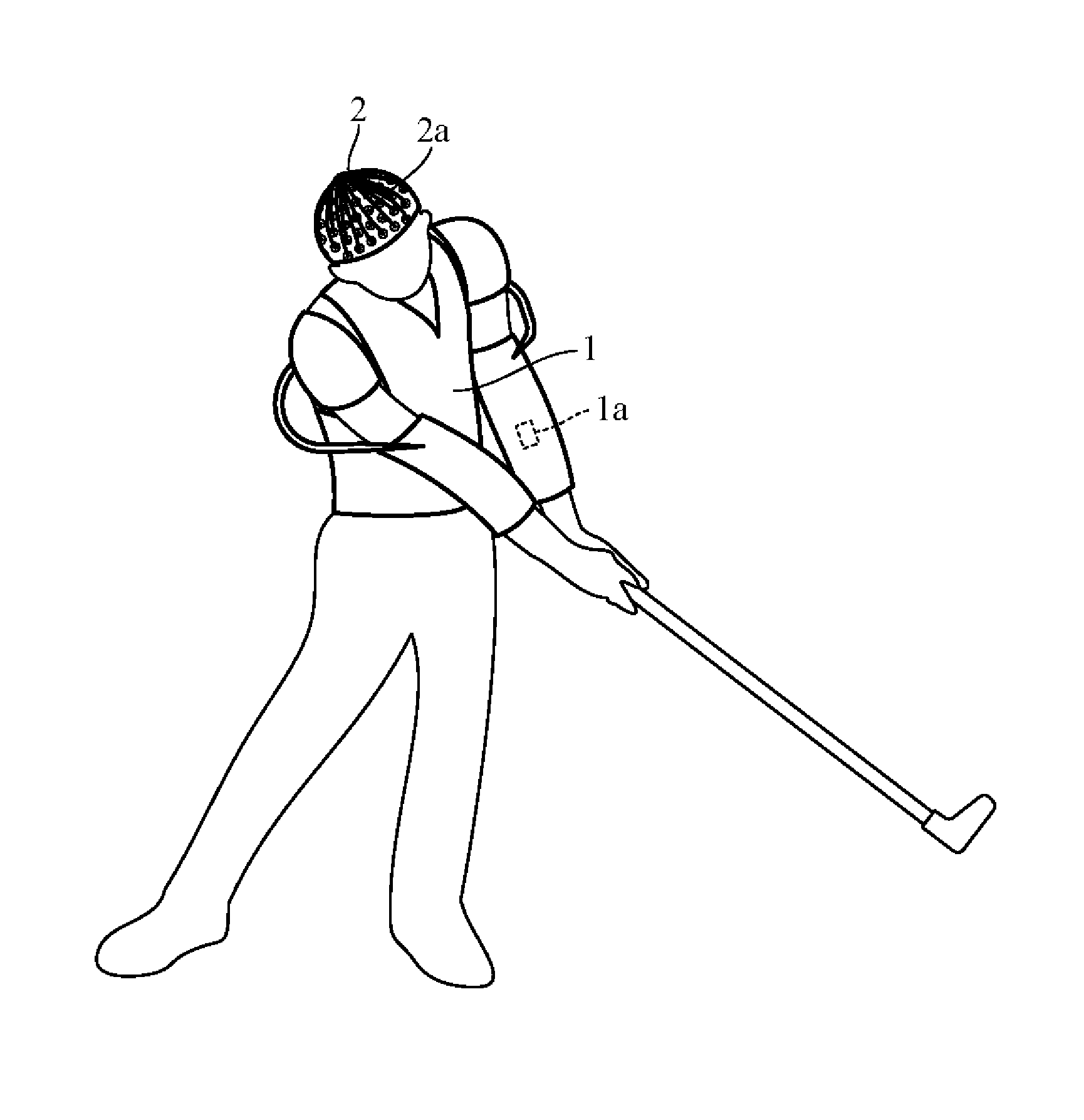
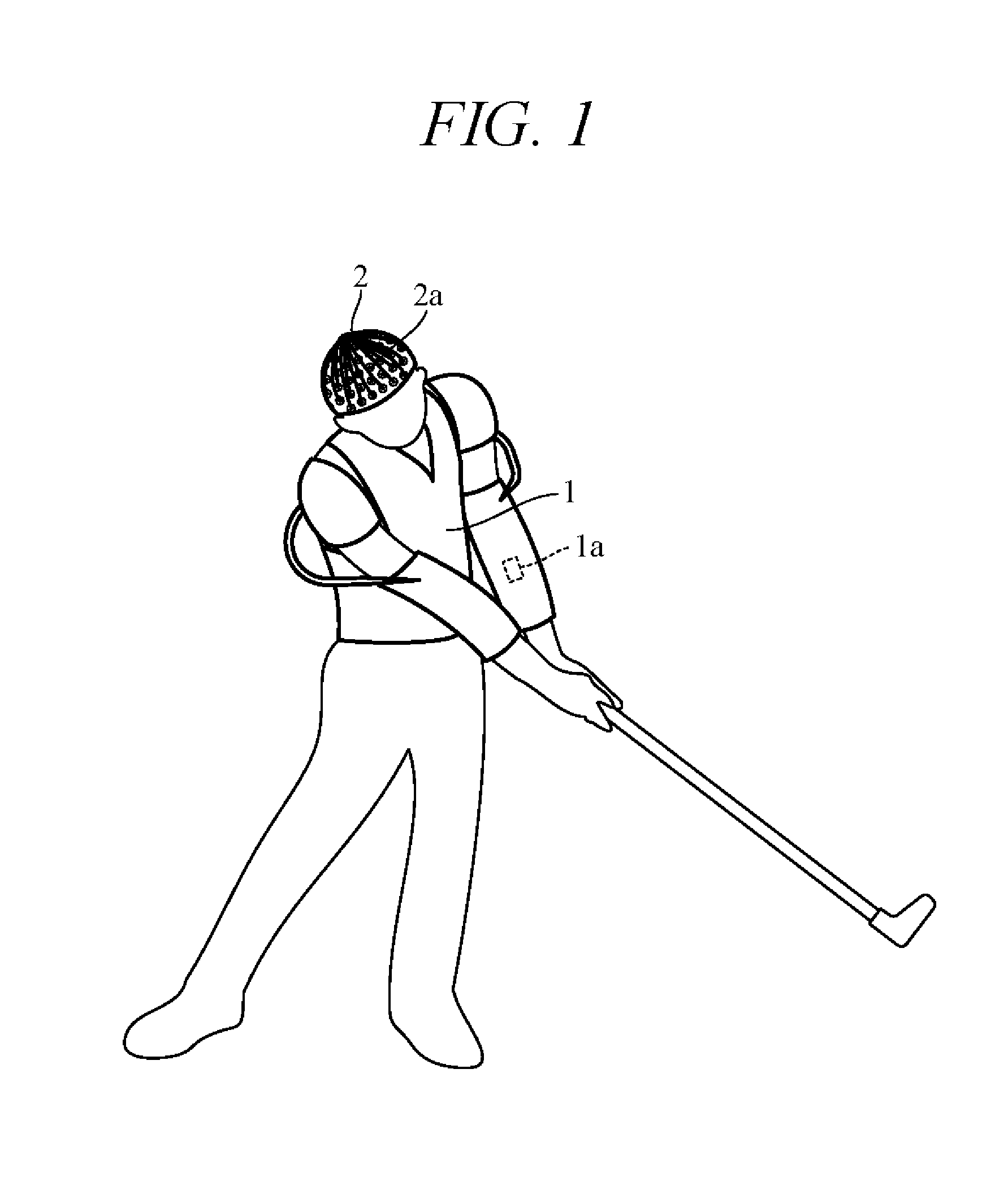
[0016] FIG. 1 is a diagram showing an example of user motion to which the motion correction apparatus according to the present embodiment is applied. As shown in FIG. 1, motion correction equipment 1 is fitted on a user's body (upper body and/or arms, for example) by means of straps and other fittings. The equipment 1 incorporates, for example, multiple electrode pads 1a (only one shown) at predetermined positions corresponding to muscles most strongly affecting swing motion. Electric current can therefore be applied to the electrode pads 1a to impart properly timed electrical stimuli to predetermined muscle positions. As a result, swing motion can be corrected by causing muscles at predetermined positions to perform contracting motions independent of the user consciousness.
[0017] Alternatively, correction of swing motion can be achieved by incorporating electric motors or other such actuators into the equipment 1 and outputting control signals to the actuators so as to operate them to apply properly timed external forces of predetermined magnitude to predetermined positions of the user's body.
[0018] Optionally, cap-shaped equipment 2, for example, is fitted on the user's head instead of, or in addition to, the equipment 1 worn on the user's body. The equipment 2 incorporates, for example, one or more electrodes 2a at positions corresponding to areas of the brain that instruct muscle movements. Electric current can therefore be applied to the electrodes 2a to impart electrical stimuli to brain areas. As a result, swing motion can be corrected by inducing the user to perform predetermined motions.
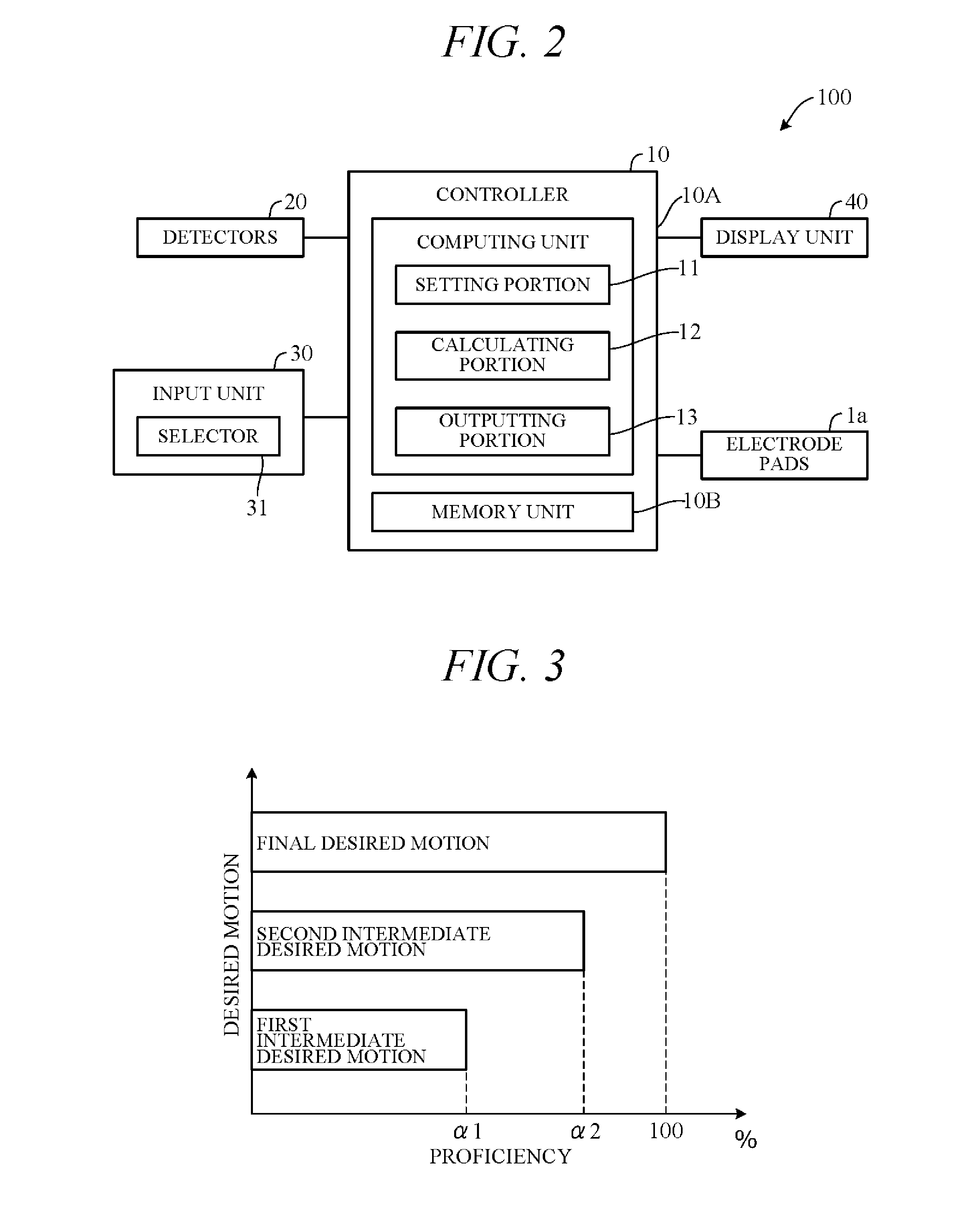
[0019] FIG. 2 is a block diagram showing essential components of a motion correction apparatus 100 according to an embodiment of the present invention. As shown in FIG. 2, the motion correction apparatus 100 is centered on a controller 10 to which detectors 20, an input unit 30, a display unit 40, and the electrode pads 1a are electrically connected by wired or wireless connection. When the user wears the equipment 2, the electrodes 2a are connected to the controller 10. When the equipment 1 incorporates actuators (electric motors), the actuators are connected to the controller 10.
[0020] The detectors 20 include one or more CCD or other image sensor-equipped cameras for imaging user swing motions. User swing motion characteristics, i.e., swing trajectory, timing, speed and the like, can be detected from picture signals produced by these cameras. Various sensors can be used in the detectors 20 instead of, or in addition to cameras, including, for example, acceleration sensors for detecting acceleration and force acting on certain parts of the user's body, force sensors, and displacement sensors for detecting displacement and angular change of certain parts of the user's body. Some or all of such sensors can be incorporated in the equipment 1 and 2. The equipment 2 in particular can be provided with sensors for detecting brain activity including, for example, sensors for detecting brain waves/electroencephalographic waves and state of brain blood flow. Signals from the detectors 20 are sent to the controller 10.
[0021] The input unit 30 comprises various switches, a keyboard, a touch panel and the like that can be operated by the user to input various instructions and data to the controller 10. The input unit 30 also includes a microphone the user can use to vocally input various instructions and information. The input unit 30 has a selector 31 as a functional constituent. The selector 31 is responsive to a selection operation by the user for selecting a single operation from among multiple operations stored in the controller 10 (a memory unit 15 thereof).
[0022] The display unit 40 includes a monitor responsive to instructions from the controller 10 for informing the user of various information. The display unit 40 can, for example, display user actual swing motion (actual motion), desired swing motion (desired motion), degree of difference between actual motion and desired motion (attainment gap versus desired motion), and so forth. The display unit 40 can also be adapted to guide the user in operating the input unit 30 by, for example, showing a list operations selectable using the selector 31. Although not illustrated in the drawings, a speaker can be connected to the controller 10 for vocally announcing information.
[0023] The controller 10 has a computer comprising a CPU or other computing unit 10A, a memory unit 10B including ROM, RAM and the like, and other peripheral circuits. The computing unit 10A comprises a setting portion 11, a calculating portion 12 and an outputting portion 13 as functional constituents. Optionally, some functions of the controller 10 can be shared among multiple intercommunicating controllers.
[0024] Multiple desired motions are stored in the controller 10 in advance. These desired motions include swing motions of professional golfer A, professional golfer B, and a number of other professional golfers. These desired motions can include various different swing motions to be recommended in accordance with attributes of the user including, for example, gender, age, and golf skill level. Swing motions directed to increasing ball flight distance, curing hook or slice, and other such purposes can also be included among the desired motions. The controller 10 can be adapted to acquire desired motions from external servers and the like for storage in the memory unit 10B.
[0025] The setting portion 11 sets a desired motion selected by the user using the selector 31 as a final desired motion. For example, it sets a swing motion of professional golfer A or professional golfer B as the final swing motion. In addition, the setting portion 11 sets one or more motion steps as intermediate desired motions (phases) up to the final swing motion. The intermediate desired motions are lower skill level motions than the final desired motion.
[0026] FIG. 3 is a diagram showing an example of desired motions set by the setting portion 11. In the example of FIG. 3, a final desired motion and two intermediate motion phases (first intermediate desired motion and second intermediate desired motion) are set. Defining proficiency of the final desired motion as 100%, the first intermediate desired motion is set at a considerably lower proficiency of .alpha.1 (e.g., 30%) and the second intermediate desired motion is set at a somewhat less lower proficiency of .alpha.2 (e.g., 60%). Before setting the desired motion to the final desired motion, the setting portion 11 sets proficiencies .alpha.1 and .alpha.2 of intermediate desired motions predetermined in accordance with difference between final desired motion and user actual motion, i.e. in accordance with attainment degree gap between actual motion and final desired motion.
[0027] The calculating portion 12 of FIG. 2 calculates degree of difference between user actual motion detected by the detectors 20 and desired motion set by the setting portion 11. For example, it calculates degree of difference regarding swing motion aspects such as trajectory, speed and timing. Specifically the calculating portion 12 calculates degree .beta.(%) actual motion attainment with respect to desired motion defined as 100% attainment.
[0028] The outputting portion 13 sends the electrode pads 1a control signals based on attainment degree .beta. calculated by the calculating portion 12. In other words, the outputting portion 13 sends the electrode pads 1a motion correction control signals for improving user actual motions toward desired motions, e.g., larger electric signals in proportion as the attainment degree .beta. is smaller. The outputting portion 13 also sends the display unit 40 control signals to display desired motion attainment degree .beta. and other information on the display unit 40.
[0029] FIG. 4 is a flowchart showing an example of processing performed by the computing unit 10A in accordance with a program loaded in the memory unit 10B in advance, particularly an example of processing related to control of the electrode pads 1a. The processing shown in this flowchart is started, for example, when the user operates a start switch or the like of the input unit 30 after selecting the final desired motion through the selector 31.
[0030] First, in S1 (S: processing Step), initial actual motion of the user detected by the detectors 20 is read. Next, in S2, initial actual motion and actual motion attainment degree .beta. with respect to the final desired motion selected in the selector 31 (initial attainment degree) are calculated, and initial desired motion is set in accordance with the calculated initial attainment degree. For example, a target value of attainment degree with respect to the desired motion, namely, a target attainment degree .beta.a (e.g., 90%), is defined in advance, and the desired motion is set in accordance with the size of the attainment degree .beta. and target attainment degree .beta.a. In the example of FIG. 3, initial desired motion is set as first intermediate desired motion when initial attainment degree .beta. is less than .alpha.1 .times..beta.a, as second intermediate desired motion when initial attainment degree .beta. is equal to or greater than .alpha.1 .times..beta.a and less than .alpha.2 .times..beta.a, and as final actual motion when initial attainment degree .beta. is equal to or greater than .alpha.2.times..beta.a. Optionally, value of target attainment degree .beta.a can be changed every desired motion step rather than being set at a fixed value.
[0031] In S2, desired motion is upgraded until desired motion reaches final desired motion. For example, when first intermediate desired motion is set as initial desired motion in first processing run of S2, second intermediate desired motion is set as desired motion in following processing run of S2, and final desired motion is set in next following processing run of S2.
[0032] In step S3, user actual motion detected by the detectors 20 is read. Next, in S4, degree of difference between detected swing motion and desired motion, i.e., attainment degree .beta. of actual motion with respect to desired motion (intermediate desired motion or final desired motion), is calculated. Next, in S5, whether calculated attainment degree .beta. is equal to or greater than target attainment degree .beta.a is determined. When the result in S5 is NO, the program goes to S6.
[0033] In S6, motion correction processing for correcting user swing motion is performed. Specifically, during user swing motion, properly timed control signals matched to attainment degree .beta. are output to electrode pads 1a at selected locations. For example, electric signals larger in proportion as attainment degree is smaller are output to selected electrode pads 1a so as to stimulate muscle movements that improve user actual motion toward desired motion. Upon completion of motion correction processing, the program returns to S3 to repeat the aforesaid processing.
[0034] On the other hand, when the result in S5 YES, the program goes to S7 to determine whether the desired motion set in S2 is the final desired motion, i.e., whether user actual motion attainment degree .beta. (percent) is equal to or greater than target attainment degree .beta.a and has reached the desired motion proficiency (100%). When the result in S7 is NO, the program returns to S2 to set a new desired motion. For example, when the immediately preceding desired motion was the first intermediate desired motion of FIG. 3, the second intermediate desired motion, and when it was the second intermediate desired motion of FIG. 3, the final desired motion, is set as the new desired motion. When the result in S7 is YES, the processing is terminated.
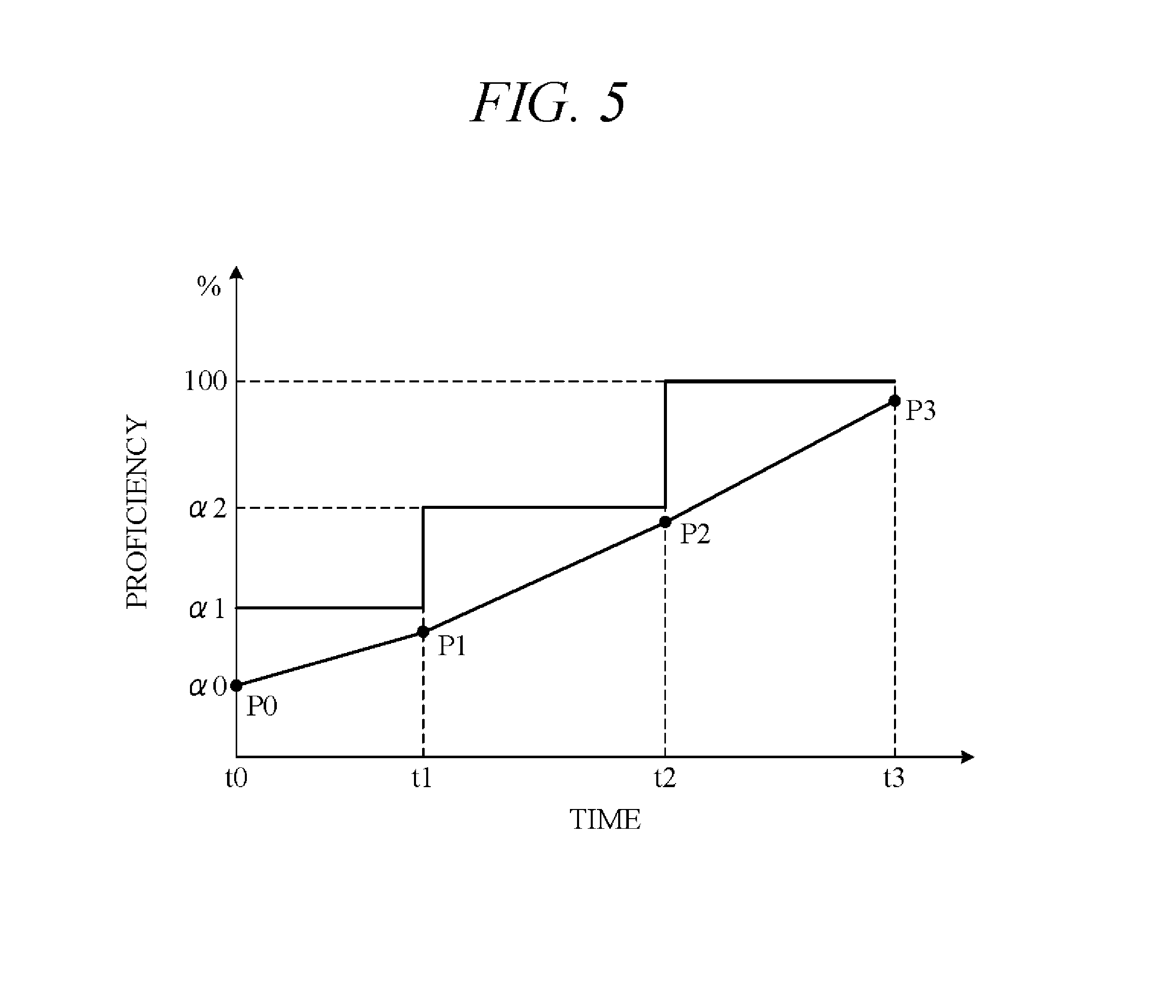
[0035] Main operations of the motion correction apparatus according to the present embodiment are concretely explained in the following. FIG. 5 is a diagram showing an example of user proficiency progress over time. As shown in FIG. 5, where level (proficiency) of initial user swing motion detected by the detectors 20 at initial time t0 is .alpha.0 (point P0), first intermediate desired motion is set as the desired motion (S2). Motion correction processing is then performed in accordance with degree of user's actual motion attainment with respect to the first intermediate desired motion so as to improve user actual motion toward the first intermediate desired motion (S6).
[0036] As the user's swing motion proficiency increases over time and actual motion attainment degree .beta. with respect to the first intermediate desired motion (proficiency .alpha.1) reaches or exceeds target attainment degree .beta.a (e.g., 90%) (point P1) at time t1, i.e., when user proficiency approaches .alpha.1 to within a predetermined degree, a new desired motion (second intermediate desired motion) is set (S5.fwdarw.S7.fwdarw.S2). Motion correction processing is then performed in accordance with degree of user' s actual motion attainment with respect to the second intermediate desired motion so as to improve user actual motion toward the second intermediate desired motion (S6).
[0037] As actual motion attainment degree .beta. with respect to the second intermediate desired motion (proficiency level .alpha.2) increases with further passage of time to reach or exceed target attainment degree .beta.a (point P2) at time t2, another new desired motion (final desired motion) is set. Motion correction processing is then performed in accordance with degree of user's actual motion attainment with respect to the final desired motion so as to improve user actual motion toward the final desired motion. When user actual motion attainment degree .beta. reaches or exceeds target attainment degree .beta.a and degree of user's swing motion increases to substantially 100% (point P3) at time t3, motion correction processing is terminated.
[0038] Owing to the adoption of a configuration that gradually increases desired motion level in this way, divergence between actual motion and desired motion can be constantly maintained within a predetermined range. As a result, user swing motion can be easily and efficiently improved by motion correction performed by operating the electrode pads 1a with minimum burden on the user.
[0039] The present embodiment can achieve advantages and effects such as the following:
[0040] (1) The motion correction apparatus 100 includes: the setting portion 11 for setting desired golf swing motion; the detectors 20 for detecting user swing motion; the equipment 1 (electrode pads 1a) for correcting user motion by applying electrical stimuli to the body of the user; and the outputting portion 13 for outputting control signals to the electrode pads 1a in accordance with user actual motion attainment with respect to desired motion so as to improve actual motion detected by the detectors 20 toward desired motion (FIG. 2). Desired motion includes final desired motion and intermediate desired motion set in steps up to final desired motion (first intermediate desired motion and second intermediate desired motion) (FIG. 3). Owing to adoption of such a configuration that operates the equipment 1 to apply electrical stimuli to the user's body, sets stepwise intermediate desired motions up to final desired motion, and gradually increases desired motion level, user swing motion proficiency can be simply and efficiently improved.
[0041] (2) The outputting portion 13 first outputs control signals to the electrode pads la in accordance with actual motion attainment degree .beta. with respect to intermediate desired motion so as to improve user motion detected by the detectors 20 toward intermediate desired motion. Next, when actual motion attainment degree .beta. with respect to intermediate desired motion reaches or exceeds target attainment degree .beta.a, the outputting portion 13 outputs control signals to the electrode pads 1a in accordance with actual motion attainment degree .beta. with respect to final desired motion so as to improve actual motion detected by the detectors 20 toward final desired motion. By gradually increasing desired motion level in this manner, user swing motion can be gradually and efficiently upgraded to final desired motion.
[0042] (3) The motion correction apparatus 100 additionally includes the selector 31 for selecting one among multiple final desired motions in response to an instruction from the user (FIG. 2). The setting portion 11 implements the final desired motion selected by the selector 31. The outputting portion 13 outputs control signals to the electrode pads 1a so as to induce the user to improve actual motion detected by the detectors 20 toward the final desired motion set by the setting portion 11. Since the user is therefore able to correct swing motion toward a final desired motion he or she prefers among multiple final desired motions, the user enjoys a high degree of satisfaction. If swing motions of professional golfer A and professional golfer B, for example, are included among candidate swing motions selectable by the user, the user can easily master swing motions of a favorite professional golfer.
[0043] (4) The electrode pads 1a are incorporated in the equipment 1 worn on the user's body, and the outputting portion 13 outputs control signals to the electrode pads la in accordance with actual motion attainment degree .beta. with respect to the desired motion. The application of electrical stimuli to the user's body in accordance with attainment degree .beta. in this manner enables easy correction of the user's swing motion.
[0044] (5) The motion correction method includes the steps of setting desired motion (S2), detecting user actual motion relative to desired motion (S3), and correcting user motion by applying external electrical stimuli to the body of the user in accordance with user actual motion attainment with respect to desired motion and thereby improve detected actual motion toward desired motion (S6). Desired motion includes final desired motion and intermediate desired motion set in steps up to final desired motion. This enables easy and efficient improvement of improvement of user swing motion proficiency.
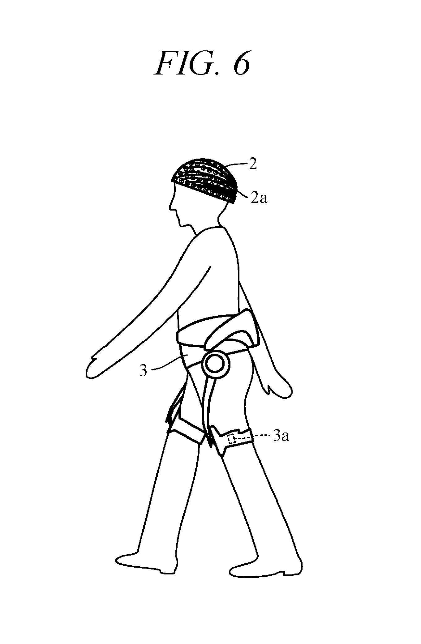
[0045] Various modifications of the aforesaid embodiment are possible. One example is explained in the following. FIG. 6 is a diagram showing a modification of the embodiment of FIG. 1. In FIG. 6, equipment 3 for correcting walking motion is fitted on a user's body (lower body, for example). This equipment 3 incorporates, for example, multiple electrode pads 3a (only one shown) at positions corresponding to muscles most strongly affecting walking motion, and properly timed electrical stimuli are applied through the electrode pads 3a to muscles at certain positions. As a result, user walking motion can be corrected. Optionally, the equipment 2 can be worn on the user's head and used to correct walking motions.
[0046] Motions that can be corrected by the motion correction apparatus are not limited to those mentioned above. The equipment fitted on the user's body or brain is therefore not limited to that mentioned above. In other words, the equipment 1 to 3 can be of any configuration insofar it is adapted to correct user motion by applying external stimuli to the user's body or brain. The aforesaid embodiment is adapted to store desired golf swing motions in the memory unit 10B, but target motions of other types can also be stored in the memory unit 10B. The aforesaid embodiment is adapted to detect user swing motion using the detectors 20, but the detection unit can be suitably modified in accordance with target motion. The configuration of the outputting portion 13 is not limited to the aforesaid insofar as it enables output of control signals to the motion correction unit in accordance with user actual motion attainment with respect to target motion and thereby improves actual motion detected by the detection unit toward target motion.
[0047] In the aforesaid embodiment (FIG. 3), the setting portion 11 is adapted to set the final desired motion, first intermediate desired motion and second intermediate desired motion, but insofar as a stepwise approach to final target motion is established, it can be adapted to set a single intermediate target motion or three or more intermediate target motions. Moreover, when user initial motion level is already near final desired motion, intermediate target motion can be skipped and final target motion set from the start.
[0048] The aforesaid embodiment is adapted to use the motion correction apparatus 100 to correct golf swing motion, but the motion correction apparatus of this invention can be similarly applied to, inter alia, various cases of motion correction of sports other than golf as well as of motions other than sports (e.g., rehabilitation motion).
[0049] The above embodiment can be combined as desired with one or more of the above modifications. The modifications can also be combined with one another.
[0050] According to the present invention, it is possible to easily and effectively correct user motion.
[0051] Above, while the present invention has been described with reference to the preferred embodiments thereof, it will be understood, by those skilled in the art, that various changes and modifications may be made thereto without departing from the scope of the appended claims.
* * * * *
D00000
D00001
D00002
D00003
D00004
D00005
XML
uspto.report is an independent third-party trademark research tool that is not affiliated, endorsed, or sponsored by the United States Patent and Trademark Office (USPTO) or any other governmental organization. The information provided by uspto.report is based on publicly available data at the time of writing and is intended for informational purposes only.
While we strive to provide accurate and up-to-date information, we do not guarantee the accuracy, completeness, reliability, or suitability of the information displayed on this site. The use of this site is at your own risk. Any reliance you place on such information is therefore strictly at your own risk.
All official trademark data, including owner information, should be verified by visiting the official USPTO website at www.uspto.gov. This site is not intended to replace professional legal advice and should not be used as a substitute for consulting with a legal professional who is knowledgeable about trademark law.