Variable Mode Pulse Indicator
AL-ALI; Ammar
U.S. patent application number 16/117691 was filed with the patent office on 2019-03-28 for variable mode pulse indicator. The applicant listed for this patent is Masimo Corporation. Invention is credited to Ammar AL-ALI.
| Application Number | 20190090764 16/117691 |
| Document ID | / |
| Family ID | 39303893 |
| Filed Date | 2019-03-28 |


| United States Patent Application | 20190090764 |
| Kind Code | A1 |
| AL-ALI; Ammar | March 28, 2019 |
VARIABLE MODE PULSE INDICATOR
Abstract
A user configurable variable mode pulse indicator provides a user the ability to influence outputs indicative of a pulse occurrence at least during distortion, or high-noise events. For example, when configured to provide or trigger pulse indication outputs, a pulse indicator designates the occurrence of each pulse in a pulse oximeter-derived photo-plethysmograph waveform, through waveform analysis or some statistical measure of the pulse rate, such as an averaged pulse rate. When the configured to block outputs or not trigger pulse indication outputs, a pulse indicator disables the output for one or more of an audio or visual pulse occurrence indication. The outputs can be used to initiate an audible tone "beep" or a visual pulse indication on a display, such as a vertical spike on a horizontal trace or a corresponding indication on a bar display. The amplitude output is used to indicate data integrity and corresponding confidence in the computed values of saturation and pulse rate. The amplitude output can vary a characteristic of the pulse indicator, such as beep volume or frequency or the height of the visual display spike.
| Inventors: | AL-ALI; Ammar; (San Juan Capistrano, CA) | ||||||||||
| Applicant: |
|
||||||||||
|---|---|---|---|---|---|---|---|---|---|---|---|
| Family ID: | 39303893 | ||||||||||
| Appl. No.: | 16/117691 | ||||||||||
| Filed: | August 30, 2018 |
Related U.S. Patent Documents
| Application Number | Filing Date | Patent Number | ||
|---|---|---|---|---|
| 14947224 | Nov 20, 2015 | 10064562 | ||
| 16117691 | ||||
| 11871808 | Oct 12, 2007 | 9192329 | ||
| 14947224 | ||||
| 60851861 | Oct 12, 2006 | |||
| Current U.S. Class: | 1/1 |
| Current CPC Class: | A61B 5/7405 20130101; A61B 5/742 20130101; A61B 5/6838 20130101; A61B 5/02427 20130101; A61B 5/02438 20130101; A61B 5/0002 20130101; A61B 5/6826 20130101; A61B 5/14551 20130101 |
| International Class: | A61B 5/024 20060101 A61B005/024; A61B 5/00 20060101 A61B005/00; A61B 5/1455 20060101 A61B005/1455 |
Claims
1.-8. (canceled)
9. A method of configuring output indications of pulse occurrences in an patient monitor capable of monitoring a pulse rate through a signal from a noninvasive optical sensor, the method comprising: receiving an input signal from said sensor; determining a measure of distortion in said input signal; and when said measure indicates a high level of distortion, outputting an indication of pulse occurrences according to user-selected configuration parameters.
10. The method of claim 9, wherein said indication comprises a pulse beep.
11. The method of claim 10, wherein said configuration parameters cause said pulse beep to be blocked.
12. The method of claim 10, wherein said configuration parameters cause said pulse beep to be responsive to a statistical representation of a calculated pulse rate.
13. The method of claim 9, wherein said indication comprises visual display elements.
14. The method of claim 13, wherein said configuration parameters cause at least one of said display elements to blocked.
15. The method of claim 13, wherein said configuration parameters cause at least one of said display elements to be responsive to a statistical representation of a calculated pulse rate.
Description
PRIORITY CLAIM
[0001] This present application claims priority benefit under 35 U.S.C. .sctn. 119(e) from U.S. Provisional Application No. 60/851,861, filed Oct. 12, 2006, entitled "Variable Mode Pulse Indicator," which is incorporated by reference herein.
CROSS-REFERENCE TO RELATED APPLICATIONS
[0002] The present application is related to U.S. Pat Nos. 6,606,511, 6,002,952, 6,464,311, 6,684,090, 6,770,028, 6,850,788, and the continuation, continuation-in-part, and divisional applications thereof. The present application also incorporates the foregoing disclosures herein by reference.
BACKGROUND OF THE DISCLOSURE
Field of the Disclosure
[0003] The present disclosure relates in general to patient monitoring and in particular to oximeter patient monitors capable of monitoring one or more physiological parameters including a pulse rate from a noninvasive optical sensor.
Description of the Related Art
[0004] A desirable feature of patient monitors, including oximeters such as oximeters, co-oximeters, and the like, includes at least one of an audio and video indication of a pulse occurrence substantially corresponding to a patient's pulse. Such indications of a pulse occurrence may be caused by a trigger output used to initiate an audible tone "beep" or a visual pulse indication on a display.
[0005] In some systems, when signal(s) from a noninvasive optical sensor include sufficient distortion, high noise, or simply present low signal quality, pulse indications may be difficult to calculate. In some systems, the oximeter may simply determine that no pulse indication is presented to a caregiver.
[0006] In other systems, the oximeter may attempt to determine pulse occurrences during distortion, high noise, motion-induced noise, or during low signal quality or confidence. For example, in U.S. Pat. No. 6,606,511, which is assigned to Masimo Corporation ("Masimo") of Irvine, Calif., which is the assignee of the current application and incorporated by reference herein, a pulse trigger output from a rule-based processor is responsive to pulse waveforms of the patient's oximeter-derived photo-plethysmograph waveform in low-noise or no-distortion situations. However, during high-noise or distortion situations, the pulse trigger output may advantageously become dependent on an average or other statistical determination of the pulse rate. This "intelligent beep" reliably indicates the patient's pulse, yet responds to patient arrhythmias, asystole conditions and similar irregular plethysmographs. An example of the determination of pulse rate in the presence of distortion is described in U.S. Pat. Nos. 6,002,952, 6,463,311, 6,684,090, all of which are assigned to Masimo Corporation of Irvine, Calif., and incorporated by reference herein.
[0007] As disclosed in the '511 patent, when there is relatively no distortion corrupting a plethysmograph signal, the processor may analyze the shape of the pulses in the waveform to determine where in the waveform to generate the pulse indication. When distortion is present, looser waveform criteria can be used to determine if pulses are present. For example, when pulses are present, the pulse indication is based upon an averaged pulse rate. If no pulses are present, no indication occurs.
[0008] In the disclosed embodiment, the pulse indicator provides a trigger and amplitude output. The trigger output is used to initiate an audible tone "beep" or a visual pulse indication on a display, such as a vertical spike on a horizontal trace, a rising pulsing or constant bar display, one or more specific colors of a displayed parameter or trace, one or more LEDs or other visual elements, combinations of the same, or the like. The amplitude output is used to indicate data integrity and corresponding confidence in the computed values of saturation and pulse rate. The amplitude output can vary a characteristic of the pulse indicator, such as beep volume or frequency or the height of the visual display spike.
SUMMARY OF THE DISCLOSURE
[0009] With the acceptance of oximeter systems that output audio and visual indications of pulse occurrences, caregivers have begun to rely on assumptions they make from such audio and visual queries. For example, when a caregiver is accustomed to oximeter systems that are simply silent during signal distortion, high-noise, or low signal quality conditions, that caregiver may make potentially inaccurate assumptions about a patient monitored by oximeter systems that attempt to find pulse occurrences through noise. For example, even when an oximeter system includes an output that adjusts a visual indication of a pulse occurrence to indicate poor signal conditions or low confidence in determined parameters, the actuation of an audible beep may lead a caregiver to believe that the signal conditions, and perhaps the monitored patient, are better than they actually are. Conversely, a caregiver accustomed to a monitor that attempts to provide indications of pulse occurrences through distortion and noise, such as the oximeters disclosed in the '511 patent, may make potentially inaccurate assumptions about a patient monitored by oximeter systems that simply go silent during more difficult signal conditions.
[0010] Based at least thereon, a need exists for a configurable oximeter that allows caregivers to configure pulse occurrence indications to match their expectations. Therefore, in an embodiment of the disclosure, an oximeter includes a variable mode oximetry pulse indicator responsive to modes selected by a user or caregiver. For example, one mode may disable audio and visual pulse occurrence indications, another mode may disable one or the other, and yet another mode may enable audio and visual pulse occurrence indications during defined noisy conditions. In an embodiment, the user may cycle through or otherwise select the particular mode using user configuration menus and user input devices, such as, for example, a keypad or other user interface/input device.
BRIEF DESCRIPTION OF THE DRAWINGS
[0011] A general architecture that implements the various features of the disclosure will now be described with reference to the drawings. The drawings and the associated descriptions are provided to illustrate embodiments of the disclosure and not to limit its scope.
[0012] FIGS. 1A-1D illustrate various exemplary oximeter patient monitoring systems.
[0013] FIG. 2 illustrates an exemplary block diagram of one or more of the oximeter patient monitoring systems of FIG. 1.
[0014] FIG. 3 illustrates an exemplary user interface providing user configuration of pulse indicators during signal distortion in one or more signals acquired from, for example, a non-invasive optical sensor, according to an embodiment of the disclosure.
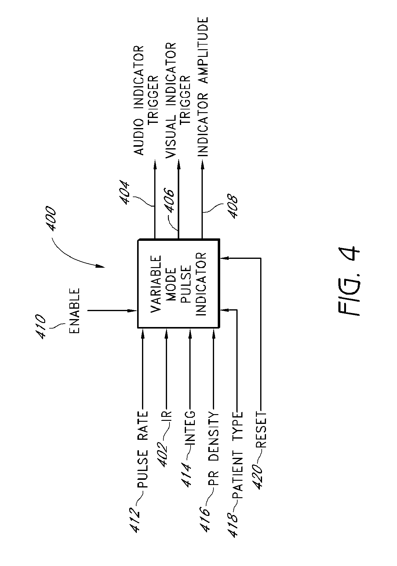
[0015] FIG. 4 illustrates exemplary inputs and outputs of a variable mode oximetry pulse indicator, according to an embodiment of the disclosure.
[0016] FIG. 5 illustrates an exemplary block diagram of a variable mode oximetry pulse indicator, according to an embodiment of the disclosure.
[0017] FIG. 6 illustrates an exemplary block diagram of an indicator decision module of the variable mode oximetry pulse indicator of FIG. 5, according to an embodiment of the disclosure.
DETAILED DESCRIPTION OF THE PREFERRED EMBODIMENT
[0018] Embodiments of the present disclosure include a user configurable oximetry pulse indicator. For example, a user may configure whether one or more of audio and visual indicators of pulse occurrences is presented to a caregiver during, for example, distortion, motion-induced noise, low signal quality, or other challenging signal conditions. In an embodiment, a first mode presents audio and visual indicators of a patient's pulse to a caregiver during challenging signal conditions, while a second and third mode presents one or the other respectively, and a fourth mode blocks or otherwise diminishes the influence of the audio and visual indicators.
[0019] In an embodiment, an enable signal is generated according to the user's configurations and a pulse indicator is responsive to the enable signal. For example, a pulse indicator may advantageously determine a pulse occurrence and generate an indicator trigger. Depending upon the particular mode configured by the user, the pulse indicator trigger, and in some embodiments, a pulse indicator amplitude may advantageously be forwarded to tone and display generators. Alternatively, depending upon the particular mode, the indicator trigger and indicator amplitude may be partially or entirely blocked or otherwise diminished to match expectations of the caregiver in challenging signal conditions.
[0020] To facilitate a further understanding of the disclosure, the remainder of the description describes the invention with reference to specific drawings. Moreover, in this application, reference may be made to many blood parameters. Some references that have common shorthand designations are referenced through such shorthand designations. For example, as used herein, HbCO designates carboxyhemoglobin, HbMet designates methemoglobin, Hbt designates total hemoglobin, SpO.sub.2 designates functional arterial saturation, and SpaO.sub.2 designates fractional arterial saturation. Other shorthand designations such as COHb, MetHb, and tHb are also common in the art for these same constituents. These constituents are generally reported in terms of a percentage, often referred to as saturation, relative concentration, concentration, or fractional saturation. Total hemoglobin is generally reported as a concentration in g/dL. The use of the particular shorthand designators presented in this application does not restrict the term to any particular manner in which the designated constituent is reported.
[0021] FIG. 1A illustrates a perspective view of a patient monitor system 100, according to an embodiment of the present disclosure. The system 100 includes a portable patient monitor 102 capable of noninvasively determining one or more physiological parameters. In an embodiment, the portable patient monitor 102 mechanically and electrically mates with a docking station 104 to recharge batteries, upload and download information, upgrade software or firmware, communicate with other monitors or the like. Disclosures of various docking stations are disclosed with reference to U.S. Pat. No. 6,770,028, incorporated above.
[0022] FIG. 1A also illustrates the monitor 102 comprising one or more displays 106 capable displaying of a wide variety of measured values in a manner that provides for quick and efficient conveyance of information to a caregiver. For example, the display 106 displays values for HbCO, HbMet, MbT, SpO.sub.2, SpaO.sub.2, beats-per-minute, scaled plethysmograph data 118, PI.TM. 120 and other information.
[0023] FIG. 1B illustrates a perspective view of a monitoring system 150 including a handheld noninvasive multi-parameter patient monitor 152 communicating with a reusable optical sensor 154 through a patient cable 156, according to embodiments of the disclosure. In general, the monitor 152 drives the sensor 154 to emit light of differing wavelengths into the body tissue 158. The sensor 154 detects the light after attenuation by the body tissue 158 and outputs a signal indicative of the amount of light received by the sensor 154 through the cable 156. In addition, in some embodiments, the monitor 152 communicates with a temperature sensor and a memory device associated with one or more of the sensor 154 and the cable 156, through the cable 156.
[0024] In an embodiment, the monitors 102, 152 receive sensor output and determine continuous and non-invasive measurements of a wide variety of blood parameters. Although disclosed with reference to portable monitors 102, 152, an artisan will recognize from the disclosure herein that aspects of the present disclosure can be adopted into tabletop monitors, wireless sensors, or other patient-wearable personal monitors, or multi-parameter patient monitors.
[0025] FIG. 1B also shows the sensor 154 comprising a reusable sensor in the form a clip including a spring biased pivot point capable of removably attaching the reusable sensor to a patient's finger 158. Although disclosed with reference to a reusable sensor having a spring, an artisan will recognize from the disclosure herein that the sensor 154 can advantageously comprise a disposable adhesive type sensor, a combination sensor including reusable and disposable components, components incorporated into other medical devices such as catheters, or the like, or other reusable sensor designs. Moreover, the artisan will recognize from the disclosure herein that the sensor 154 can comprise mechanical structures, adhesive or other tape structures, Velcro wraps or combination structures specialized for the type of patient, type of monitoring, type of monitor, or the like. In an embodiment, the sensor 154 provides data to the monitors 102, 152 and vice versa through the cable 156, although such communication can advantageously be wireless, over public or private networks or computing systems or devices, through intermediate medical or other devices, combinations of the same, or the like.
[0026] In an embodiment, the monitor 152 includes one or more displays 160 capable of displaying, for example, one or more of the foregoing parameters. For example, the display 160 may provide an indication of HbCO, HbMet, Hbt, SpO.sub.2, SpaO.sub.2, pulse rate, plethysmographs, historical or trending data, confidence or perfusion indicators, or the like. The monitors 102, 152 may include one or more audio, visual or messaging (pagers, emails, instant and phone messages, vocally presented numbers, messages and alarms, voice-over-IP ("VOIP") interfaces and functionality, or the like) alarms, user input keypad 160, or the like.
[0027] Although described in terms of certain embodiments, other embodiments or combination of embodiments will be apparent to those of ordinary skill in the art from the disclosure herein. For example, the monitors 102, 152 may combine other information with intensity-derived information to influence diagnoses or device operation. For example, patterns or changes in the continuous noninvasive monitoring of intensity-derived information may cause the activation of other vital sign measurement devices, such as, for example, blood pressure cuffs.
[0028] FIG. 1C illustrates a perspective view of a monitoring system including a personal or wearable noninvasive multi-parameter patient monitor 170, according to embodiments of the disclosure. Such personal oximeters 170 generally wirelessly communicated with a monitoring station to provide the monitoring station with measurements for some or all of the physiological parameters measurable by the monitor. In an embodiment, the monitor travels with a patient as the patient, for example, moves through a care site such as a hospital. Wireless networks incorporating such personal pulse technologies are commercially available from Masimo marketed under the brand RadNet.TM., RadLink.TM. and Patient Safety Net.TM..
[0029] FIG. 1D illustrates a perspective view of a monitoring system including a wireless noninvasive multi-parameter patient monitor 190, according to embodiments of the disclosure. In an embodiment, a traditional sensor 192 communicates with a wireless transmission device 194 wearable, for example, on the wrist. In other embodiments, the wireless transmission device may advantageously be incorporated into a sensor housing adapted for wireless communication. In an embodiment, a wireless receiver 196 communicates with a sensor port 198 in the same manner as a wired sensor. Thus, in an exemplary embodiment shown in FIG. 1D, a traditional sensor 192 and a traditional sensor port 198 may be unaware that a patient cable has been replaced with wireless transmissions. Disclosure of wireless technologies is disclosed in U.S. Pat. No. 6,850,788, incorporated by reference herein.
[0030] FIG. 2 illustrates an exemplary block diagram of an embodiment of a patient monitoring system 200. As shown in FIG. 2, the system 200 includes a patient monitor 202 comprising a processing board 204 and a host instrument 208. The processing board 204 communicates with a sensor 206 to receive one or more intensity signal(s) indicative of one or more parameters of tissue of a patient. The processing board 204 also communicates with a host instrument 208 to display determined parameter values calculated using the one or more intensity signals. According to an embodiment, the board 204 comprises processing circuitry arranged on one or more printed circuit boards capable of installation into the monitor 202, or capable of being distributed as some or all of one or more OEM components for a wide variety of host instruments monitoring a wide variety of patient information. In an embodiment, the processing board 202 comprises a sensor interface 210, a digital signal processor and signal extractor ("DSP" or "processor") 212, and an instrument manager 214. In general, the sensor interface 210 converts digital control signals into analog drive signals capable of driving sensor emitters, and converts composite analog intensity signal(s) from light sensitive detectors into digital data.
[0031] In an embodiment, the sensor interface 210 manages communication with external computing devices. For example, in an embodiment, a multipurpose sensor port (or input/output port) is capable of connecting to the sensor 206 or alternatively connecting to a computing device, such as a personal computer, a PDA, additional monitoring equipment or networks, or the like. When connected to the computing device, the processing board 204 may upload various stored data for, for example, off-line analysis and diagnosis. The stored data may comprise trend data for any one or more of the measured parameter data, plethysmograph waveform data acoustic sound waveform, or the like. Moreover, the processing board 204 may advantageously download from the computing device various upgrades or executable programs, may perform diagnosis on the hardware or software of the monitor 202. In addition, the processing board 204 may advantageously be used to view and examine patient data, including raw data, at or away from a monitoring site, through data uploads/downloads, or network connections, combinations, or the like, such as for customer support purposes including software maintenance, customer technical support, and the like.
[0032] As shown in FIG. 2, the digital data is output to the DSP 212. According to an embodiment, the DSP 212 comprises a processing device based on the Super Harvard ARChitecture ("SHARC"), such as those commercially available from Analog Devices. However, a skilled artisan will recognize from the disclosure herein that the DSP 212 can comprise a wide variety of data and/or signal processors capable of executing programs for determining physiological parameters from input data. In particular, the DSP 212 includes program instructions capable of receiving multiple channels of data related to one or more intensity signals representative of the absorption (from transmissive or reflective sensor systems) of a plurality of wavelengths of emitted light by body tissue. In an embodiment, the DSP 212 accepts data related to the absorption of two (2) to eight (8) wavelengths of light, although an artisan will recognize from the disclosure herein that the data can be related to the absorption of two (2) to sixteen (16) or more wavelengths.
[0033] FIG. 2 also shows the processing board 204 including the instrument manager 214. According to an embodiment, the instrument manager 214 may comprise one or more microcontrollers controlling system management, including, for example, communications of calculated parameter data and the like to the host instrument 208. The instrument manager 214 may also act as a watchdog circuit by, for example, monitoring the activity of the DSP 212 and resetting it when appropriate.
[0034] The sensor 206 may comprise any commercially available noninvasive oximetry sensor. In an embodiment, the sensor 206 provides data to the board 204 and vice versa through, for example, a patient cable. An artisan will also recognize from the disclosure herein that such communication can be wireless, over public or private networks or computing systems or devices, or the like.
[0035] As shown in FIG. 2, the sensor 206 includes a plurality of emitters 216 irradiating the body tissue 218 with differing wavelengths of light, and one or more detectors 220 capable of detecting the light after attenuation by the tissue 218. The sensor 206 may also include other electrical components such as, for example, a memory device 222 comprising an EPROM, EEPROM, ROM, RAM, microcontroller, combinations of the same, or the like. In an embodiment, other sensor components may include a temperature determination device 223 or other mechanisms for, for example, determining real-time emission wavelengths of the emitters 216.
[0036] The memory 222 may advantageous store some or all of a wide variety data and information, including, for example, information on the type or operation of the sensor 206; type or identification of sensor buyer or distributor or groups of buyer or distributors, sensor manufacturer information, sensor characteristics including the number of emitting devices, the number of emission wavelengths, data relating to emission centroids, data relating to a change in emission characteristics based on varying temperature, history of the sensor temperature, current, or voltage, emitter specifications, emitter drive requirements, demodulation data, calculation mode data, the parameters for which the sensor is capable of supplying sufficient measurement data (e.g., HpCO, HpMet, Hbt, or the like), calibration or parameter coefficient data, software such as scripts, executable code, or the like, sensor electronic elements, whether the sensor is a disposable, reusable, multi-site, partially reusable, partially disposable sensor, whether it is an adhesive or non-adhesive sensor, whether the sensor is a reflectance, transmittance, or transreflectance sensor, whether the sensor is a finger, hand, foot, forehead, or ear sensor, whether the sensor is a stereo sensor or a two-headed sensor, sensor life data indicating whether some or all sensor components have expired and should be replaced, encryption information, keys, indexes to keys or hash functions, or the like, monitor or algorithm upgrade instructions or data, some or all of parameter equations, information about the patient, age, sex, medications, and other information that may be useful for the accuracy or alarm settings and sensitivities, trend history, alarm history, or the like. In an embodiment, the monitor may advantageously store data on the memory device, including, for example, measured trending data for any number of parameters for any number of patients, or the like, sensor use or expiration calculations, sensor history, or the like.
[0037] FIG. 2 also shows the patient monitor 202 including the host instrument 208. In an embodiment, the host instrument 208 communicates with the board 204 to receive signals indicative of the physiological parameter information calculated by the DSP 212. The host instrument 208 preferably includes one or more display devices 224 capable of displaying indicia representative of the calculated physiological parameters of the tissue 218 at the measurement site including for example pulse occurrence indicia In an embodiment, the host instrument 208 may advantageously comprise a handheld housing capable of displaying parameter data, including but not limited to pulse rate, plethysmograph data, perfusion quality such as a perfusion quality index ("PI.TM."), signal or measurement quality ("SQ"), values of blood constituents in body tissue, including for example, SpO.sub.2, HbCO, HbMet, Hbt, or the like. In other embodiments, the host instrument 208 is capable of displaying values for one or more of Hbt, Hb, blood glucose, bilirubin, or the like. The host instrument 208 may be capable of storing or displaying historical or trending data related to one or more of the measured values, combinations of the measured values, plethysmograph data, or the like. The host instrument 208 also includes an audio indicator 226 and user input device 228, such as, for example, a keypad, touch screen, pointing device, voice recognition device, or the like.
[0038] In still additional embodiments, the host instrument 208 includes audio or visual alarms that alert caregivers that one or more physiological parameters are falling below predetermined safe thresholds. The host instrument 208 may include indications of the confidence a caregiver should have in the displayed data. In a further embodiment, the host instrument 208 may advantageously include circuitry capable of determining the expiration or overuse of components of the sensor 206, including, for example, reusable elements, disposable elements, or combinations of the same.
[0039] The monitor 202 also includes a mode configuration 211 accessible to the DSP 212 and responsive to inputs from, for example, the user input device 218. The mode configuration advantageously provides a caregiver the ability to configure pulse indicators in low signal quality conditions.
[0040] Although described in terms of certain embodiments, other embodiments or combination of embodiments will be apparent to those of ordinary skill in the art from the disclosure herein. For example, the monitor 202 may comprise one or more monitoring systems monitoring parameters, such as, for example, vital signs, blood pressure, ECG or EKG, respiration, glucose, bilirubin, or the like. Such systems may combine other information with intensity-derived information to influence diagnosis or device operation. Moreover, the monitor 202 may advantageously include an audio system, preferably comprising a high quality audio processor and high quality speakers to provide for voiced alarms, messaging, or the like. In an embodiment, the monitor 202 may advantageously include an audio out jack, conventional audio jacks, headphone jacks, or the like, such that any of the display information disclosed herein may be audiblized for a listener. For example, the monitor 202 may include an audible transducer input (such as a microphone, piezoelectric sensor, or the like) for collecting one or more of heart sounds, lung sounds, trachea sounds, or other body sounds and such sounds may be reproduced through the audio system and output from the monitor 202. Also, wired or wireless communications (such as Bluetooth or WiFi, including IEEE 801.11a, b, or g), mobile communications, combinations of the same, or the like, may be used to transmit the audio output to other audio transducers separate from the monitor 202. Moreover, patterns or changes in the continuous noninvasive monitoring of intensity-derived information may cause the activation of other vital sign measurement devices, such as, for example, blood pressure cuffs.
[0041] FIG. 3 illustrates an exemplary user interface 300 providing user configuration of pulse indicators during signal distortion, according to an embodiment of the disclosure. In an embodiment, a user interacts with a user input device to configure certain behaviors of the patient monitor, including configuration of the audio and visual pulse indicators. As shown in FIG. 3, the interface 300 includes selectable or configurable parameters for one or both of the audible and visual pulse indicators 302, 304, respectively. For example, a user may determine that unless the instrument receives a strong signal quality, the user does not want to hear pulse indications; however, the user may want the visual indications to remain for purposes of trending, marking, closer inspection, diagnosis, or the like. In such case, the user may advantageously select "NO" 306 for the audio pulse indication configuration 302 and select "YES" 308 for the visual pulse indication configuration 304.
[0042] Although disclosed with reference to individual configuration of audio and visual pulse indications during low signal quality or confidence, an artisan will recognize from the disclosure herein a wide variety of user configurations as varying levels of detail to allow a user to customize the response of the patient monitor to varying signal quality. For example, the interface 300 may include configuration of modes governing the use of the pulse indicator amplitude for audio and visual indicators, configuration settings for a wide variety of differing audio and visual indications, such as, for example, coloring, trace characteristics, plethysmograph characteristics, trending characteristics, memory storage, varying frequencies, volume, voice messages, paging, other alarming, configuring the behavior of a bar graph, LED train, or the like.
[0043] FIG. 4 illustrates exemplary inputs and outputs of a variable mode oximetry pulse indicator 400, according to an embodiment of the disclosure. In an embodiment, the indicator 400 can be incorporated into an oximeter to trigger the occurrence of a synchronous indication of each of the patient's arterial pulses. The indicator 400 operates on, for example, an IR signal input 402 and generates an audio trigger output 404, a visual trigger output 406, and an amplitude output 408. The output 404 can be connected to a tone generator within the oximeter monitor 202 to create, for example, a fixed-duration audible "beep" as a pulse indication. Alternatively, or in addition, the output 406 can be connected to a display generator within the oximeter monitor 202 to create one or more visual pulse indications. The visual pulse indications can include a continuous horizontal trace on a CRT, LCD display or similar display device, where vertical spikes occur in the trace synchronously with the patient's pulse. The visual pulse indications may also include a bar display, such as a vertically- or horizontally-arranged stack of LEDs or similar display device, where, for example, the bar pulses synchronously with the patient's pulse. The visual indications may include changing colors, textual or graphical information, trace data, plethysmograph data, or the like. In an embodiment, an enable signal 410 responsive to the mode configuration 211 of FIG. 4, dictates whether all, some, or none of the outputs 404, 406 and 408 are output to the audio and visual mechanisms of the host instrument 208.
[0044] FIG. 4 also shows the amplitude output 408 used to vary one or more of the audible or visual indications so as to designate input data integrity and a corresponding confidence in the parameter and pulse rate outputs of the oximeter. For example, the height of a vertical spike can be varied in proportion to the amplitude output 408, where a large or small vertical spike would correspondingly designate high or low confidence. As another example, the amplitude output 408 can be used to vary the volume of the audible beep or to change the visual indication (e.g., change color or the like) to similarly designate a high or low confidence. One of ordinary skill in the art will recognize that the trigger outputs 404, 406 and amplitude output 408 can be utilized to generate a variety of audible and visual indications of a patient's pulse and data integrity within the scope of this disclosure.
[0045] Other inputs to the variable mode pulse indicator 400 include pulse rate 412, Integ (data integrity) 414, PR (pulse rate) density 416, patient type 418 and reset 420, which are described in detail in U.S. Pat. No. '511, referenced in the foregoing. The trigger decisions involve rule-based processes that advantageously respond to the pulse waveforms of the patient's plethysmograph in low-noise or no-distortion situations. However, the trigger decisions may become dependent on the configuration parameters to determine what, if any, outputs occur and how those outputs will be audio and/or visually communicated to a caregiver.
[0046] The pulse rate input 412 to the pulse indicator 400 provides the frequency of the patient's pulse rate in beats per minute. Pulse rate can be determined as described in U.S. patent application Ser. No. 08/834,194 or U.S. Patent Application entitled "Plethysmograph Pulse Recognition Processor," both cited above. The Integ output 414 is a measure of the integrity of the IR 402 and Red input signals. In an embodiment, the measure is derived from signals from the sensor 206 as processed by an adaptive noise canceller. The PR density input 416 may comprise a ratio of the sum of the periods of recognizable pulses within a waveform segment divided by the length of the waveform segment. This parameter represents the fraction of the waveform segment that can be classified as having physiologically acceptable pulses. In one embodiment, a segment represents a snapshot of 400 samples of a filtered input waveform, or a 6.4 second "snapshot" of the IR waveform at a 62.5 Hz sampling rate. The derivation of Integ output 414 and PR density is described in U.S. Pat. No. 6,464,311 entitled "Plethysmograph Pulse Recognition Processor," and cited above. The patient type 418 comprises a Boolean value that indicates either an adult sensor or a neonate sensor is in use. The reset 420 initializes the state of the pulse indicator 400 to known values upon power-up and during periods of recalibration, such as when a new sensor is attached or a patient cable is reconnected.
[0047] FIG. 5 illustrates an exemplary functional block diagram of a variable mode oximetry pulse indicator 400, according to an embodiment of the disclosure. As shown in FIG. 5, the indicator 400 includes a shifting buffer 510, a distortion level function 520, a waveform analyzer 530, and an indicator decision 540, which together produce the indicator triggers 404, and 406. The pulse indicator 400 also includes a scaled logarithm function 550 that produces the indicator amplitude output 408. The shifting buffer 510 accepts the IR input 402 and provides a vector output 512 representing a fixed-size segment of the patient's plethysmograph input to the waveform analyzer 530. The distortion level function 520 determines the amount of distortion present in the IR input signal 402. The inputs to the distortion level function 520 are the Integ input 414 and the PR density input 416. The distortion output 522 is a Boolean value that is "true" when distortion in the IR input 402 is above a predetermined threshold. The distortion output 522 is input to the waveform analyzer 530 and the indicator decision 540. The distortion output 522 determines the thresholds for the waveform analyzer 530. The distortion output 522 also affects the window size within which a pulse indication can occur. The distortion output 522 is also a function of the patient type input 418, which indicates whether the patient is an adult, a neonate, or the like.
[0048] In general, the waveform analyzer 530 determines whether a particular portion of the IR input 402 is an acceptable place for a pulse indication. The input to the waveform analyzer 530 is the vector output 512 from the shifting buffer 510, creating a waveform segment. A waveform segment portion meets the acceptance criteria for a pulse when it satisfies one of three conditions. These conditions are a sharp downward edge, a peak in the middle with symmetry with respect to the peak, and a peak in the middle with a gradual decline. If one of these criteria is met, the waveform analyzer "quality" output 532 is "true." Different criteria are applied depending on the state of the distortion output 522, which is also a waveform analyzer input. If the distortion output 522 indicates no distortion, strict criteria are applied to the waveform shape. If the distortion output 522 indicates distortion, looser criteria are applied to the waveform shape. Different criteria are also applied for waveforms obtained from adult and neonate patients, as indicated by the patient type 406.
[0049] The indicator decision 540 determines whether to trigger a pulse indication at a particular sample point of the input waveform. Specifically, the indicator decision 540 determines, in conjunction with the mode configuration 211, whether to, and if it is the right place to, trigger a pulse indication. The decision as to whether to trigger the pulse indication is configured by the user through the mode configuration 211. The enable signal 410 is responsive to the mode configuration 211, and, in the case one or both of the distortion and quality signals 522 and 532 indicating poor signal quality, the indicator decision 540 determines whether some, all, or none of the audio and visual triggers 404 will pass to the audio and display devices of the host instrument 208. In an embodiment, the enable signal 410 may comprise Boolean high and low signals and the mode selector may comprise logical gates configured to pass or block signals based on the enable signal 410.
[0050] In addition to the enable signals 410, the decision as to the right place to trigger a pulse indication is a function of the analyzer output 532, which is one input to the indicator decision 540. The decision as to the right time for an indicator trigger is a function of the state of the distortion output 522, which is another input to the indicator decision 540. If the distortion output 522 is "false", i.e. no distortion is detected in the input waveform, then a fixed minimum time gap from the last indicator must occur. In a particular embodiment, this minimum time gap is 10 samples. If the distortion output 522 is "true", i.e. distortion is detected in the input waveform, then the minimum time gap is a function of the pulse rate input 412. Additional details are disclosed in co-owned U.S. Pat. No. '511, referenced in the foregoing.
[0051] FIG. 6 illustrates an exemplary block diagram of the indicator decision module 540 of the variable mode oximetry pulse indicator 400 of FIG. 5, according to an embodiment of the disclosure. As shown in FIG. 6, a first stage 602 of the indicator decision 640 determines a minimum time gap after which a pulse indicator can occur. The second stage 604 determines whether the number of samples since the last indicator is greater than the minimum allowed pulse gap. The third stage 606 decides whether to generate a pulse indicator trigger. If no trigger occurs, a sample count is incremented. If an indicator trigger occurs, the sample count is reset to zero.
[0052] The first stage 602 has a divider 610, a truncation 620 and a first multiplexer 630. These components function to set the minimum allowable gap between pulse indications. Under no distortion, the minimum gap is 10 samples. Under distortion, the gap is determined by the pulse rate. Specifically, under distortion, the minimum gap is set at about 80% of the number of samples between pulses as determined by the pulse rate input 402. This may be computed as about 0.8 times the sample frequency, such as, for example, 62.5 Hz., divided by the pulse rate in pulses per second.
[0053] The divider 610 computes 3000/pulse rate. The divider output 612 is truncated 620 to an integer value. The first multiplexer 630 selects the minimum gap as either 10 samples if the distortion input 622 is "false" or the truncated value of 3000/pulse rate if the distortion input 622 is "true." The selected value is provided on the multiplexer output 632, which is fed to the second stage 604. The second stage 604 is a comparator 640, which provides a Boolean output 642 that is "true" if a counter output 652 has a value that is equal to or greater than the minimum gap value provided at the first multiplexer output 632.
[0054] FIG. 6 also illustrates the third stage 606, which has a counter and one or more mode selector function. The counter comprises a delay element 650 providing the counter output 652, an adder 660 and a second multiplexer 670. When the counter is initialized, the second multiplexer 670 provides a zero value on the multiplexer output 672. The multiplexer output 672 is input to the delay element, which delays the multiplexer output value by one sample period before providing this value at the counter output 652. The counter output 652 is incremented by one by the adder 660. The adder output 662 is input to the second multiplexer 662, which selects the adder output 662 as the multiplexer output 672 except when the counter is initialized, as described above. The counter is initialized to zero when the pulse indicator trigger 404, 406 are "true" as determined by the output of the mode selectors 680.
[0055] The mode selectors 680 include inputs of the quality 532, the distortion 522, the enable signal 410, and the output of the comparator 642, and respectively outputs the triggers 404, 406. In an embodiment, the mode selectors 680 each comprise a logical combination of the input signals to determine the output signal. For example, a mode selector 680 may advantageously logically "OR" the quality and distortion signals 532, 522, respectively, and logically "AND" that output with the enable signal 410, and the comparator output 642. In such an embodiment, when either the quality signal 532 or the distortion signal 522 indicates less than ideal qualities in the input IR signal 402, the mode configuration 211 governs whether the output signals 404, 406 are triggered. Other embodiments could logically "AND" all the signals to require both the quality signal 532 and the distortion signal 522 to indicate poor signal quality from the sensor before the mode configuration 211 takes over. In still other embodiments, the logical combinations could be part of the mode configuration and the user may control how the signal are combined to determine whether to trigger one or more of the output signals 404, 406. Moreover, an artisan will recognize from the disclosure herein a number of logical combinations of input signals that allow the mode configuration 211 to dictate the behavior of a patient monitor with respect to at least the pulse indications when the signal quality is less than ideal.
[0056] While variable mode pulse indicator has been described, other embodiments of the present disclosure will be known to those of skill in the art from the descriptions herein. Moreover, those of skill in the art understand that information and signals can be represented using a variety of different technologies and techniques. For example, data, instructions, commands, information, signals, bits, symbols, and chips that can be referenced throughout the above description may be represented by voltages, currents, electromagnetic waves, magnetic fields or particles, optical fields or particles, or any combination thereof.
[0057] Those of skill in the art further appreciate that the various illustrative logical blocks, modules, circuits, and algorithm steps described in connection with the embodiments disclosed herein can be implemented as electronic hardware, computer software, or combinations of both. To illustrate this interchangeability of hardware and software, various illustrative components, blocks, modules, circuits, and steps have been described above generally in terms of their functionality. Whether such functionality is implemented as hardware or software depends upon the particular application and design constraints imposed on the overall system. Skilled artisans can implement the described functionality in varying ways for each particular application, but such implementation decisions should not be interpreted as causing a departure from the scope of the present invention.
[0058] The various illustrative logical blocks, modules, and circuits described in connection with the embodiments disclosed herein can be implemented or performed with a general purpose processor, a digital signal processor (DSP), an application specific integrated circuit (ASIC), a field programmable gate array (FPGA) or other programmable logic device, discrete gate or transistor logic, discrete hardware components, or any combination thereof designed to perform the functions described herein. A general purpose processor can be a microprocessor, but in the alternative, the processor can be any conventional processor, controller, microcontroller, or state machine. A processor can also be implemented as a combination of computing devices, e.g., a combination of a DSP and a microprocessor, a plurality of microprocessors, one or more microprocessors in conjunction with a DSP core, or any other such configuration.
[0059] The steps of a method or algorithm described in connection with the embodiments disclosed herein can be embodied directly in hardware, in a software module executed by a processor, or in a combination of the two. A software module can reside in RAM memory, flash memory, ROM memory, EPROM memory, EEPROM memory, registers, hard disk, a removable disk, a CD-ROM, or other form of storage medium known in the art. A storage medium is coupled to the processor, such that the processor can read information from, and write information to, the storage medium. In the alternative, the storage medium can be integral to the processor. The processor and the storage medium can reside in an ASIC. The ASIC can reside in a user terminal, physiological monitor and/or sensor. The processor and the storage medium can reside as discrete components in a user terminal, physiological monitor and/or sensor.
[0060] Although the foregoing disclosure has been described in terms of certain preferred embodiments, other embodiments will be apparent to those of ordinary skill in the art from the disclosure herein. Additionally, other combinations, omissions, substitutions and modifications will be apparent to the skilled artisan in view of the disclosure herein. Moreover, it is contemplated that various aspects and features of the invention described can be practiced separately, combined together, or substituted for one another, and that a variety of combination and subcombinations of the features and aspects can be made and still fall within the scope of the invention. Furthermore, the systems described above need not include all of the modules and functions described in the preferred embodiments. Accordingly, the present invention is not intended to be limited by the recitation of the preferred embodiments, but is to be defined by reference to the appended claims.
[0061] Additionally, all publications, patents, and patent applications mentioned in this specification are herein incorporated by reference to the same extent as if each individual publication, patent, or patent application was specifically and individually indicated to be incorporated by reference.
* * * * *
D00000
D00001
D00002
D00003
D00004
D00005
D00006
D00007
D00008
D00009
XML
uspto.report is an independent third-party trademark research tool that is not affiliated, endorsed, or sponsored by the United States Patent and Trademark Office (USPTO) or any other governmental organization. The information provided by uspto.report is based on publicly available data at the time of writing and is intended for informational purposes only.
While we strive to provide accurate and up-to-date information, we do not guarantee the accuracy, completeness, reliability, or suitability of the information displayed on this site. The use of this site is at your own risk. Any reliance you place on such information is therefore strictly at your own risk.
All official trademark data, including owner information, should be verified by visiting the official USPTO website at www.uspto.gov. This site is not intended to replace professional legal advice and should not be used as a substitute for consulting with a legal professional who is knowledgeable about trademark law.