Sole Structure For Shoes And Shoe Including The Same
Sato; Natsuki ; et al.
U.S. patent application number 16/137893 was filed with the patent office on 2019-03-28 for sole structure for shoes and shoe including the same. The applicant listed for this patent is Mizuno Corporation. Invention is credited to Shin Hirai, Kouji Ito, Shogo Matsui, Ken Nishikawa, Natsuki Sato.
| Application Number | 20190090583 16/137893 |
| Document ID | / |
| Family ID | 65638375 |
| Filed Date | 2019-03-28 |


| United States Patent Application | 20190090583 |
| Kind Code | A1 |
| Sato; Natsuki ; et al. | March 28, 2019 |
SOLE STRUCTURE FOR SHOES AND SHOE INCLUDING THE SAME
Abstract
A sole includes a sole body supporting an entire planta of a wearer, lower protrusions protruding downward from a lower portion of the sole body toward the ground and spaced from each other, and upper protrusions protruding upward from an upper portion of the sole body toward a planta of a wearer, each of the upper protrusions being on the sole body and overlapping with an associated one of the lower protrusions. Each of the lower protrusions has, at its lower portion, a first region which makes contact with the ground, and each of the upper protrusions has, at its upper portion, a second region which makes contact with the planta of the wearer and is smaller than the first region.
| Inventors: | Sato; Natsuki; (Osaka, JP) ; Ito; Kouji; (Osaka, JP) ; Matsui; Shogo; (Osaka, JP) ; Hirai; Shin; (Osaka, JP) ; Nishikawa; Ken; (Osaka, JP) | ||||||||||
| Applicant: |
|
||||||||||
|---|---|---|---|---|---|---|---|---|---|---|---|
| Family ID: | 65638375 | ||||||||||
| Appl. No.: | 16/137893 | ||||||||||
| Filed: | September 21, 2018 |
| Current U.S. Class: | 1/1 |
| Current CPC Class: | A43B 13/14 20130101; A43B 13/184 20130101; A43B 13/141 20130101; A43B 7/146 20130101; A43B 7/1475 20130101; A43B 7/149 20130101; A43B 17/003 20130101 |
| International Class: | A43B 13/18 20060101 A43B013/18; A43B 7/14 20060101 A43B007/14; A43B 17/00 20060101 A43B017/00 |
Foreign Application Data
| Date | Code | Application Number |
|---|---|---|
| Sep 28, 2017 | JP | 2017-188242 |
| Jun 28, 2018 | JP | 2018-122900 |
Claims
1. A sole structure for shoes, the sole structure comprising: a sole body supporting an entire planta of a wearer; a plurality of lower protrusions protruding downward from a lower portion of the sole body toward the ground, and spaced from each other; and a plurality of upper protrusions protruding upward from an upper portion of the sole body toward the planta of the wearer, each of the upper protrusions being on an upper side of the sole body and overlapping with an associated one of the lower protrusions, each of the lower protrusions has, at its lower portion, a first region which makes contact with the ground, and each of the upper protrusions has, at its upper portion, a second region which makes contact with the planta of the wearer and is smaller than the first region.
2. The sole structure of claim 1, wherein each of the lower protrusions is substantially pillar-shaped, and a bottom surface of each of the upper protrusions serves as the first region.
3. The sole structure of claim 1, wherein the second regions of the upper protrusions vary in size depending on their positions with respect to portions of the planta of the wearer.
4. The sole structure of claim 1, wherein the upper protrusions vary in height depending on their positions with respect to portions of the planta of the wearer.
5. A shoe comprising the sole structure of claim 1.
6. A shoe comprising the sole structure of claim 2.
7. A shoe comprising the sole structure of claim 3.
8. A shoe comprising the sole structure of claim 4.
9. The shoe of claim 5, further comprising: an upper attached to an upper side of the sole structure, wherein the upper includes an upper body and an insole integrated with the upper body.
10. The shoe of claim 5, further comprising: an inner sole arranged on the upper side of the sole structure.
11. The shoe of claim 9, further comprising: an inner sole arranged on the upper side of the sole structure.
Description
CROSS-REFERENCE TO RELATED APPLICATION
[0001] This application claims priority to Japanese Patent Applications No. 2017-188242, filed on Sep. 28, 2017, and No. 2018-122900, filed on Jun. 28, 2018, the entire disclosures of which are incorporated by reference herein.
BACKGROUND ART
[0002] The present disclosure relates to a sole structure for shoes, and a shoe including the sole structure.
[0003] A sole structure for shoes has been disclosed by, for example, Japanese Unexamined Patent Publication No. 2014-144170. The sole structure includes a plurality of first protrusions protruding downward from a lower surface of a sole body toward the ground and spaced from each other, and a plurality of second protrusions protruding upward from an upper surface of the sole body toward the planta of a wearer of the shoes (will be hereinafter simply referred to as a "wearer") and spaced from each other. Each of the first protrusions is arranged to oppose to an associated one of the second protrusions in the vertical direction with the sole body interposed between them. Each of the first protrusions has a lower end in the shape of a hemisphere so that the lower end makes contact with the ground in a relatively small area. In this sole structure, the area of contact between the first protrusion and the ground is substantially the same as an area of contact between the second protrusion and the planta of the wearer.
SUMMARY
[0004] According to the sole structure of Japanese Unexamined Patent Publication No. 2014-144170, when a foot of the wearer (the sole structure) makes contact with the ground, a reaction force acted on the sole structure from the ground is transferred to the second protrusions from the first protrusions via the sole body. As a result, the reaction force is transferred to the planta of the wearer.
[0005] In the sole structure of Japanese Unexamined Patent Publication No. 2014-144170, the lower end of each first protrusion makes contact with the ground in a relatively small area, and the area of contact between the first protrusion and the ground is substantially the same as an area of contact between the second protrusion and the planta of the wearer. In this configuration, the reaction force generated upon contact with the ground tends to be dispersed during the transfer from the first protrusions to the second protrusions. Thus, the reaction force cannot be accurately transferred from the second protrusions to portions of the planta of the wearer. As a result, the wearer cannot recognize the differences of pressures transferred to the portions of his or her planta upon contact with the ground, and therefore, cannot easily control his or her body movement by timely recognizing the load applied to each portion of the planta upon contact with the ground.
[0006] In view of the foregoing, it is therefore an object of the present disclosure to allow the wearer to timely recognize the load applied to each portion of the planta upon contact with the ground, so that he or she can easily control his or her body movement.
[0007] To achieve the object, a first aspect of the present disclosure is directed to a sole structure for shoes. The sole structure includes a sole body supporting an entire planta of a wearer; a plurality of lower protrusions protruding downward from a lower portion of the sole body toward the ground, and spaced from each other; and a plurality of upper protrusions protruding upward from an upper portion of the sole body toward the planta of the wearer, each of the upper protrusions being on an upper side of the sole body and overlapping with an associated one of the lower protrusions, each of the lower protrusions has, at its lower portion, a first region which makes contact with the ground, and each of the upper protrusions has, at its upper portion, a second region which makes contact with the planta of the wearer and is smaller than the first region.
[0008] In the first aspect, when the wearer's foot makes contact with the ground during his or her movement, such as walking, running, or jumping, a reaction force from the ground acts on the lower protrusions, and is transferred from the lower protrusions to the wearer's planta F via the upper protrusions on the upper side of the sole body 3 respectively overlapping with the lower protrusions. Since the second regions of the upper protrusions are smaller than the first regions of the lower protrusions, the reaction force generated upon contact with the ground is concentrated from the first regions to the second regions. As a result, the reaction force is transferred as an amplified pressure from the second regions of the upper protrusions to the portions of to the planta of the wearer. As a result, the wearer can recognize the differences of pressures transferred to the portions of his or her planta upon contact with the ground. Therefore, in the first aspect, the wearer can easily control his or her body movement by timely recognizing the load applied to each portion of the planta upon contact with the ground.
[0009] A second aspect is an embodiment of the first aspect. In the second aspect, each of the lower protrusions is substantially pillar-shaped, and a bottom surface of each of the upper protrusions serves as the first region.
[0010] In the second aspect, the first regions are formed as relatively wide flat surfaces, which allows the reaction force from the ground to be easily transferred the first regions. As a result, the reaction force generated upon contact with the ground can be suitably transferred from the first regions to the second regions.
[0011] A third aspect of the present disclosure is an embodiment of the first aspect. In the third aspect, the second regions of the upper protrusions vary in size depending on their positions with respect to portions of the planta of the wearer.
[0012] In the third aspect, the reaction force generated upon contact with the ground can be suitably transferred to portions of the planta. In particular, an excessive pressure that may be applied to a portion, sensitive to pain, of the planta F can be controlled.
[0013] A fourth aspect of the present disclosure is an embodiment of the first aspect. In the fourth aspect, the upper protrusions vary in height depending on their positions with respect to portions of the planta of the wearer.
[0014] In the fourth aspect, the reaction force generated upon contact with the ground can be suitably transferred to the portions of the planta. In particular, an excessive pressure that may be applied to a portion, sensitive to pain, of the planta F can be controlled.
[0015] A fifth aspect is directed to a shoe including the sole structure of any one of the first to fourth aspects.
[0016] In the fifth aspect, shoes can be provided with the same advantageous as those of the first to fourth aspects.
[0017] A sixth aspect of the present disclosure is an embodiment of the fifth aspect. In the sixth aspect, the shoe further includes an upper attached to an upper side of the sole structure, wherein the upper includes an upper body and an insole integrated with the upper body.
[0018] In the sixth aspect, the shoe has the upper including the upper body and the insole, and therefore, can be produced more easily than a shoe with no insole.
[0019] A seventh aspect is an embodiment of the fifth or sixth aspect. In the seventh aspect, the shoe further includes an inner sole arranged on the upper protrusions.
[0020] In the seventh aspect, the inner sole is arranged on the upper protrusions. Thus, the inner sole is interposed between the sole structure and the wearer's planta. Specifically, the upper protrusions make contact with the planta via the inner sole. Thus, even if an excessive pressure is applied to the planta by the upper protrusions, for example, the inner sole can control the pressure applied to the planta.
[0021] According to the present disclosure, the wearer can easily control his or her body movement by timely recognizing the load applied to each portion of the planta upon contact with the ground.
BRIEF DESCRIPTION OF THE DRAWINGS
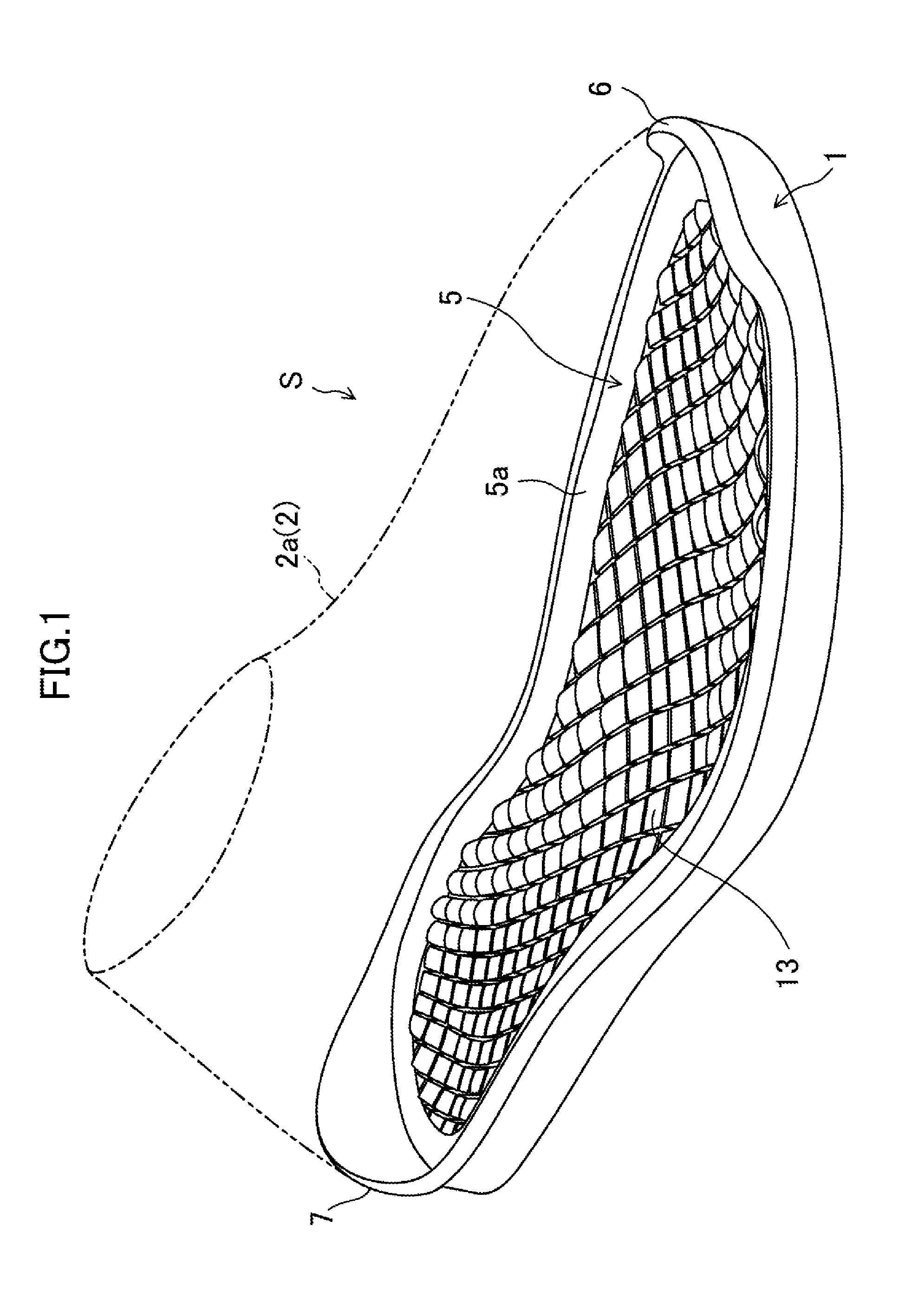
[0022] FIG. 1 is a top perspective view illustrating a sole structure of an embodiment of the present disclosure.
[0023] FIG. 2 is a bottom perspective view illustrating the sole structure of the embodiment of the present disclosure.
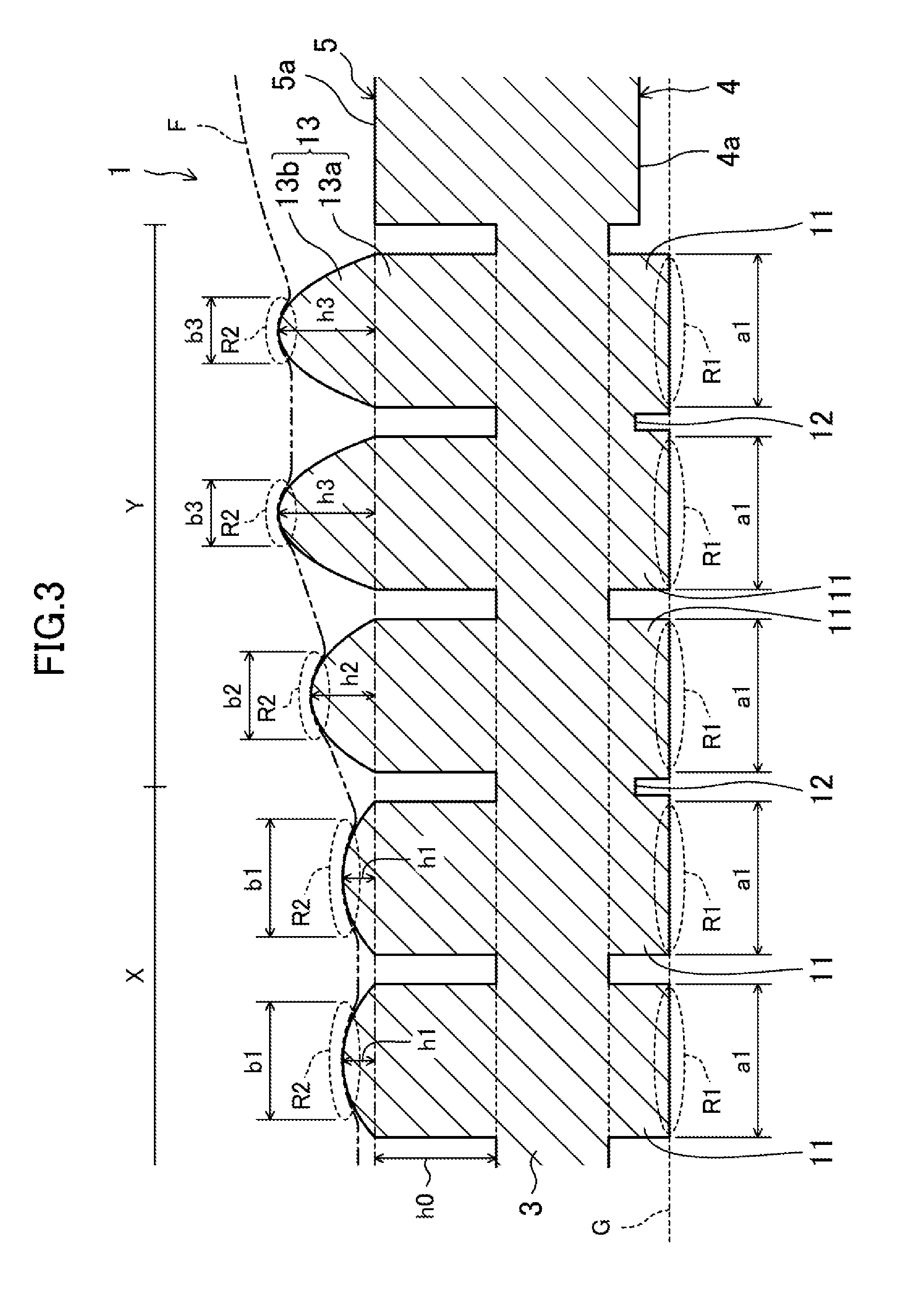
[0024] FIG. 3 is a vertical cross-sectional view illustrating a portion of the sole structure on an enlarged scale.
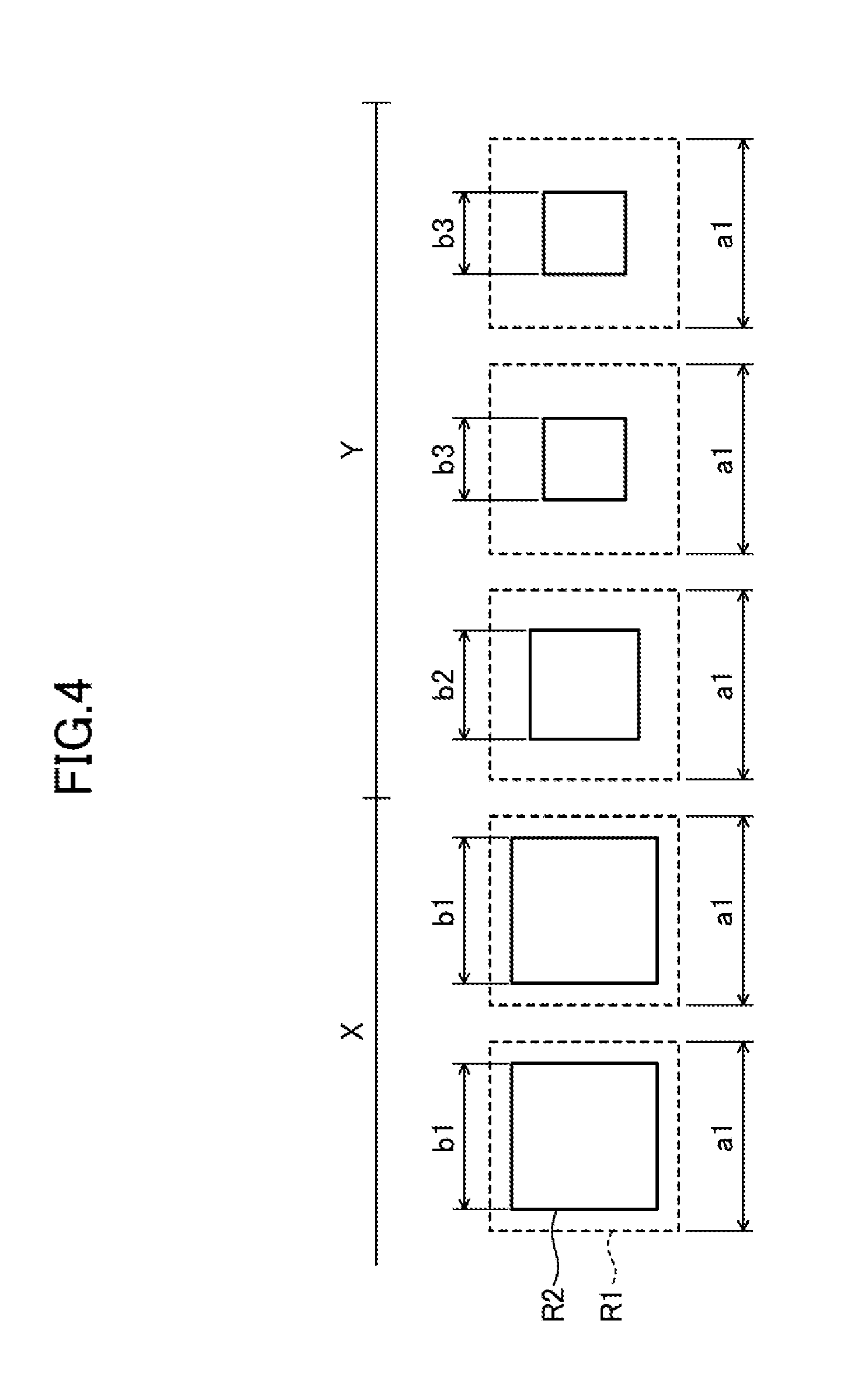
[0025] FIG. 4 is a top schematic view illustrating how first regions and second regions overlap with each other.
[0026] FIG. 5 is a schematic plan view illustrating a positional relationship between the sole structure and a skeletal structure of a foot.
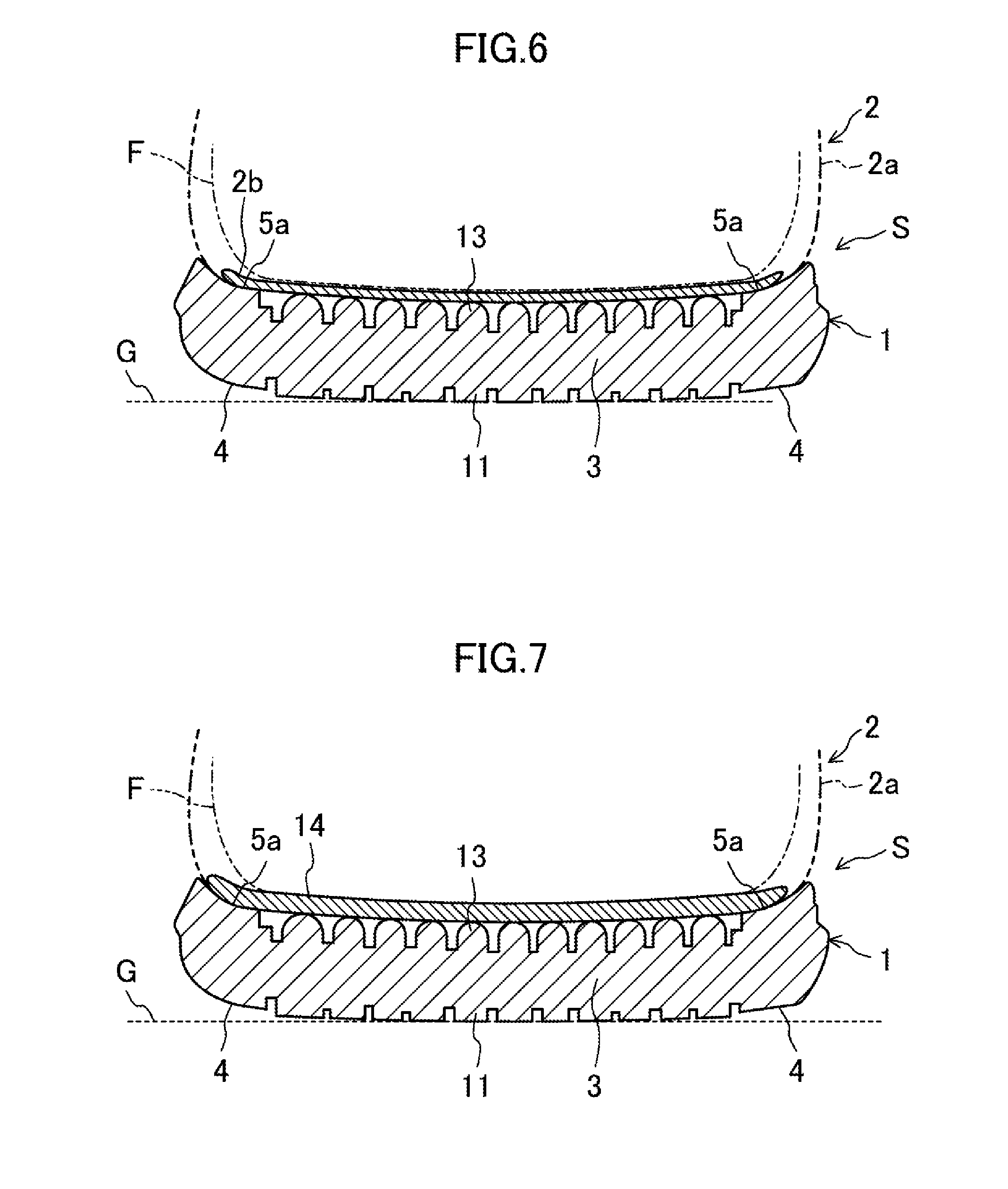
[0027] FIG. 6 is a vertical cross-sectional view of a shoe according to a first variation of the embodiment.
[0028] FIG. 7 is a vertical cross-sectional view of a shoe according to a second variation of the embodiment.
DETAILED DESCRIPTION
[0029] An embodiment of the present disclosure will be described in detail with reference to the drawings. Note that the following description of the embodiment is merely an example in nature, and is not intended to limit the scope, applications, or use of the present disclosure.
[0030] FIGS. 1 and 2 respectively illustrate a general view of a shoe S according to an embodiment of the present disclosure. The shoe S is applied to, for example, sport shoes used in various kinds of sports such as running and ball games, shoes for daily use, and shoes for rehabilitation.
[0031] The drawings illustrate a right shoe S only as an example. Since the left shoe is symmetrical to the right shoe, only the right shoe will be described in the following description, and the description of the left shoe will be omitted herein.
[0032] In the following description, the expressions "above," "upward," "on," "upper," "below," "under," "lower," and "downward," represent the vertical positional relationship between respective parts of the shoe S, and "front," "fore," "rear," and "hind" represent the longitudinal positional relationship between respective parts of the shoe S.
[0033] As shown in FIGS. 1 and 2, the shoe S has a sole 1. The sole 1 extends from a forefoot to hindfoot of a foot of a person wearing the shoe S (will be hereinafter referred to as the "wearer"). The sole 1 is made of, for example, an elastic material. Non-limiting suitable examples of the material for the sole 1 include thermoplastic synthetic resins such as ethylene-vinyl acetate copolymer (EVA) and foams thereof, thermosetting resins such as polyurethane (PU) and foams thereof, and rubber materials such as butadiene rubber and chloroprene rubber and foams thereof An upper 2 which covers the wearer's foot is attached to a peripheral portion of the sole 1 (see phantom lines in FIGS. 1 and 2).
[0034] In this embodiment, the upper 2 is comprised of an upper body 2a. The upper body 2a mainly covers an instep of the wearer's foot. The upper body 2a has a lower end which is open and corresponds to the position of an upper peripheral portion 5, which will be described later, of the sole 1. The upper body 2a is attached to the sole 1 with the lower end fixed to the upper peripheral portion 5. Specifically, the lower end of the upper body 2a is fixed, for example, with an adhesive, or by sewing, to an upper surface 5a of the upper peripheral portion 5.
[0035] As shown in FIG. 3, the sole 1 has a sole body 3. The sole body 3 supports an entire planta F of the wearer. Specifically, the sole body 3 is substantially in the shape of a plate, and extends in the longitudinal and width directions of the shoe S to correspond to the entire planta F of the wearer.
[0036] As illustrated in FIGS. 2 and 3, a lower peripheral portion 4 integrated with the sole body 3 is provided for a lower side of the sole 1. The lower peripheral portion 4 has a lower surface 4a located below the lower end of the sole body 3, and surrounds the outer periphery of the sole body 3.
[0037] As illustrated in FIGS. 1 and 3, the upper peripheral portion 5 integrated with the sole body 3 is provided for an upper side of the sole 1. The upper peripheral portion 5 has an upper surface 5a located above the upper end of the sole body 3, and surrounds the outer periphery of the sole body 3. The upper peripheral portion 5 has a curved front wall 6 at its front end, and a curved rear wall 7 at its rear end.
[0038] As shown in FIGS. 2 and 3, the sole 1 has a plurality of lower protrusions 11. Each of the lower protrusions 11 is in the shape of a quadrangular prism which is square-shaped when viewed in section, for example, and protrudes downward from the lower side of the sole body 3 toward the ground G. Specifically, each lower protrusion 11 has a lower portion located below the lower surface 4a of the lower peripheral portion 4. The lower protrusions 11 are spaced from each other.
[0039] An adjacent pair of lower protrusions 11 forms a groove 12 between them. The groove 12 is an upward recess formed from the bottom surfaces of the lower protrusions 11. The groove 12 has a smaller width and depth than the lower protrusions 11.
[0040] As shown in FIGS. 1 and 3, the sole 1 has a plurality of upper protrusions 13. Each of the upper protrusions 13 protrudes upward from the upper portion of the sole body 3 toward the planta F of the wearer. Specifically, each upper protrusion 13 has a base 13a, and a tip end 13b integrated with the base 13a. The base 13a is in the shape of a quadrangular prism which is square-shaped when viewed in section, for example, and has a height h0 from the upper portion of the sole body 3 to be substantially flush with the upper peripheral portion 5. The tip end 13b has a height h1, h2, or h3 from the upper end of the base 13a, and is tapered as it goes upward. Specifically, each upper protrusion 13 has an upper portion located above the upper surface 5a of the upper peripheral portion 5. In a preferred embodiment, the tip end 13b has a hemispherical vertex when viewed in section.
[0041] The upper protrusions 13 are spaced from each other, and each of the upper protrusions 13 is paired with an associated one of the lower protrusions 11 when viewed in section. Specifically, each of the upper protrusions 13 on the upper side of the sole body 3 overlaps with an associated one of the lower protrusions 11.
[0042] As shown in FIGS. 3 and 4, each of the lower protrusions 11 has, at is lower portion, a first region R1 which makes contact with the ground G (a soil surface or a floor). Specifically, each of the first regions R1 is a bottom surface of the quadrangular prism-shaped lower protrusion 11, and has sides, each having a dimension a1, when viewed in plan. Each of the upper protrusions 13 has, at its upper portion, a second region R2 which makes contact with the planta F of the wearer. Each of the second regions R2 is substantially in the shape of a square, each side of which has a dimension b1, b2, or b3 smaller than the dimension a1, when viewed in plan. Specifically, the second regions R2 of the upper protrusions 13 are smaller than the first regions R1 of the lower protrusions 11.
[0043] In FIG. 5, a region including a thenar and heel of the wearer's planta F is hatched with dots as a region X, and a region except for the region X (e.g., a region including a portion corresponding to a plantar arch of the planta F) is hatched with diagonal lines as a region Y.
[0044] As shown in FIG. 3, the regions R2 of the upper protrusions 13 vary in size in accordance with the portions of the wearer's planta F. Specifically, as also shown in FIG. 4, each of the second regions R2 of the upper protrusions 13 in the region X has sides each having the dimension b1. On the other hand, each of the second regions R2 of the upper protrusions 13 in the region Y has sides each having the dimension b2 or b3. The dimension b1 is larger than the dimensions b2 and b3. The dimension b2 is larger than the dimension b3. Since the dimensions vary in this manner, the upper protrusions 13 in the region X have larger second regions R2 than the upper protrusions 13 in the region Y. Specifically, the upper protrusions 13 in the region X have a larger contact area with the wearer's planta F than the upper protrusions 13 in the region Y.
[0045] As shown in FIG. 3, the upper protrusions 13 vary in height in accordance with the portions of the wearer's planta F. Specifically, the upper protrusions 13 in the region X have a height h0+h1. On the other hand, the upper protrusions 13 in the region Y have a height h0+h2 or h0+h3. The height hl is smaller than the heights h2 and h3. The height h2 is smaller than the height h3. Since the heights vary in this manner, the upper protrusions 13 in the region X are shorter than the upper protrusions 13 in the region Y.
Advantages of Embodiment
[0046] With the sole 1 configured as described above, when the wearer's foot makes contact with the ground G during his or her movement, such as walking, running, or jumping, a reaction force from the ground G acts on the lower protrusions 11, and is transferred from the lower protrusions 11 to the wearer's planta F via the upper protrusions 13 on the upper side of the sole body 3 respectively overlapping with the lower protrusions 11. Since the second regions R2 of the upper protrusions 13 are smaller than the first regions R1 of the lower protrusions 11, the reaction force generated upon contact with the ground is concentrated from the first regions R1 to the second regions R2. Thus, the reaction force is transferred as an amplified pressure from the second regions R2 of the upper protrusions 13 to the portions of the wearer's planta F. As a result, the wearer can recognize the differences of pressures transferred to the portions of his or her planta F upon contact with the ground. Therefore, the sole 1 of the shoe S of this embodiment allows the wearer to easily control his or her body movement by timely recognizing the load applied to each portion of the planta F upon contact with the ground.
[0047] Further, each of the lower protrusions 11 is pillar-shaped, e.g., substantially in the shape of a quadrangular prism as described above, and a bottom surface thereof serves as the first region R1. In this configuration, the first regions R1 are formed as relatively wide flat surfaces, which allows the reaction force from the ground G to be easily transferred to the first regions R1. As a result, the reaction force generated upon contact with the ground can be suitably transferred from the first regions R1 to the second regions R2.
[0048] Moreover, the upper protrusions 13 have the second regions R2 which vary in size depending on their positions with respect to the portions of the wearer's planta F. Thus, the reaction force generated upon contact with the ground can be suitably transferred to the portions of the planta F. In particular, an excessive pressure that may be applied to a portion, sensitive to pain, of the planta F can be controlled.
[0049] In addition, the upper protrusions 13 vary in height depending on their positions with respect to the portions of the wearer's planta F. Thus, the reaction force generated upon contact with the ground can be suitably transferred to the portions of the planta F. In particular, an excessive pressure that may be applied to a portion, sensitive to pain, of the planta F can be controlled.
[0050] Still further, since the upper protrusions 13 in the region X are made shorter than the upper protrusions 13 in the region Y, bending of the upper protrusions 13 in the region X can be avoided, irrespective of the magnitude of the reaction force transferred from the corresponding lower protrusions 11.
(First Variation of Embodiment)
[0051] In the above embodiment, it has been described that the shoe S has the upper 2 including the upper body 2a only. However, this is merely a non-limiting example. For example, the upper 2 may have an insole 2b in addition to the upper body 2a, just like a shoe S of a first variation shown in FIG. 6.
[0052] The insole 2b is made of, for example, a flexible mesh fabric. In a preferred embodiment, the insole 2b may have a suitable thickness, and be made of a suitable material, for transferring the reaction force to the wearer's planta from the upper protrusions 13. As shown in FIG. 6, the insole 2b covers the lower open end of the upper body 2a, and is interposed in the vertical direction between the planta F of the wearer wearing the shoe S and the sole 1.
[0053] The insole 2b is integral with the upper body 2a. Specifically, at least ends of the insole 2b in the width direction of the shoe S are fixed, for example, with an adhesive, or by sewing, to a lower end of the upper body 2a. Further, the ends of the insole 2b and the lower end of the upper body 2a are fixed, for example, with an adhesive, or by sewing, to the upper surface 5a of the upper peripheral portion 5.
[0054] The insole 2b is arranged on the upper protrusions 13. Specifically, the insole 2b is arranged with its middle portion in the width direction of the shoe S faces the upper protrusions 13 in the vertical direction.
[0055] As can be seen in the foregoing, the shoe S of the first variation has the upper 2 including the upper body 2a and the insole 2b, and therefore, can be produced more easily than a shoe whose upper 2 has no insole 2b.
[0056] Further, in the shoe S of the first variation, the upper protrusions 13 make contact with the planta F via the insole 2b. Thus, even if an excessive pressure is applied to the planta F by the upper protrusions 13, for example, the insole 2b can control the pressure applied to the planta F.
(Second Variation of Embodiment)
[0057] In the above embodiment, it has been described that the upper protrusions 13 directly make contact with the wearer's planta F. However, this is merely a non-limiting example. For example, the upper protrusions 13 may indirectly make contact with the wearer's planta F via an inner sole 14, just like in a shoe S of a second variation shown in FIG. 7.
[0058] The inner sole 14 is made of a cloth such as a knitted, woven, or nonwoven fabric. In a preferred embodiment, the inner sole 14 may have a suitable thickness, and be made of a suitable material, for transferring the reaction force to the wearer's planta from the upper protrusions 13. As shown in FIG. 7, the inner sole 14 is arranged on the upper protrusions 13. Specifically, the inner sole 14 is arranged with its middle portion in the width direction of the shoe S faces the upper protrusions 13 in the vertical direction. That is, the inner sole 14 is interposed between the planta F of the wearer wearing the shoe S and the sole 1. The inner sole 14 may have a peripheral portion fixed, for example, with an adhesive, or by sewing, to the upper surface 5a of the upper peripheral portion 5.
[0059] As can be seen in the foregoing, in the shoe S of the second variation, the upper protrusions 13 make contact with the planta F via the inner sole 14. Thus, even if an excessive pressure is applied to the planta F by the upper protrusions 13, for example, the inner sole 14 can control the pressure applied to the planta F.
Other Embodiments
[0060] In the above embodiment, it has been described that the sole 1 includes the sole body 3 made of a single material. However, this is merely a non-limiting example. For example, the sole 1 may be comprised of an outsole (not shown) made of a hard elastic material with high hardness, and a midsole (not shown) made of a soft elastic material. In this configuration, the lower protrusions 11 may be provided for a lower surface of the outsole corresponding to the lower portion of the sole body 3, and the upper protrusions 13 may be provided for an upper surface of the midsole corresponding to the upper portion of the sole body 3.
[0061] In the above embodiments, it has been described that each of the lower protrusions 11 is in the shape of a quadrangular prism. However, this is merely a non-limiting example. For example, each of the lower protrusions 11 may be in the shape of a triangular prism, or a circular column. The lower protrusions 11 may have any shape as long as they are substantially pillar-shaped.
[0062] In the first variation of the embodiment, it has been described that the insole 2b is made of a flexible mesh fabric. However, this is merely a non-limiting example. For example, the insole 2b may be made of any one of a knitted fabric, a woven fabric, a nonwoven fabric, a cloth, or a foam of resin and/or rubber.
[0063] The insole 2b may be made of two or more layers. The layers may be made of the same material, or different materials.
[0064] In the second variation of the embodiment, it has been described that the inner sole 14 is fixed, for example, with an adhesive or by sewing, to the upper surface 5a of the upper peripheral portion 5 of the sole 1. However, this is merely a non-limiting example. For example, the inner sole 14 may be detachably arranged with its peripheral portion located on the upper surface 5a of the upper peripheral portion 5 of the sole 1.
[0065] In the above embodiment, it has been described that the lower end of the upper body 2a is directly fixed with an adhesive to the upper surface 5a of the upper peripheral portion 5. However, this is merely a non-limiting example. For example, in the assembly of the shoe S, an additional step may be performed. In this step, an intermediate body (not shown) is formed by temporarily fixing an insole (not shown) made of a water-soluble material (such as pulpwood) to the lower end of the upper body 2a and the upper surface 5a of the upper peripheral portion 5. Then, this intermediate body is immersed in an aqueous solution to dissolve the insole only. Through this step, the shoe S can be easily produced as in the first variation described above.
[0066] In the first variation of the embodiment, the inner sole 14 of the second variation may be arranged on the insole 2b.
[0067] Note that the present disclosure is not limited to the embodiment described above, and various changes and modifications may be made without departing from the scope of the present disclosure.
INDUSTRIAL APPLICABILITY
[0068] The present disclosure is industrially applicable to, for example, sport shoes used in various kinds of sports such as running and ball games, training shoes for such sports, sneakers for daily use, and shoes for rehabilitation.
* * * * *
D00000
D00001
D00002
D00003
D00004
D00005
D00006
XML
uspto.report is an independent third-party trademark research tool that is not affiliated, endorsed, or sponsored by the United States Patent and Trademark Office (USPTO) or any other governmental organization. The information provided by uspto.report is based on publicly available data at the time of writing and is intended for informational purposes only.
While we strive to provide accurate and up-to-date information, we do not guarantee the accuracy, completeness, reliability, or suitability of the information displayed on this site. The use of this site is at your own risk. Any reliance you place on such information is therefore strictly at your own risk.
All official trademark data, including owner information, should be verified by visiting the official USPTO website at www.uspto.gov. This site is not intended to replace professional legal advice and should not be used as a substitute for consulting with a legal professional who is knowledgeable about trademark law.