Interlocking Co-molded Helmet Energy Management Liner
Shaffer; Samuel J.
U.S. patent application number 15/713517 was filed with the patent office on 2019-03-28 for interlocking co-molded helmet energy management liner. The applicant listed for this patent is Bell Sports, Inc.. Invention is credited to Samuel J. Shaffer.
| Application Number | 20190090574 15/713517 |
| Document ID | / |
| Family ID | 63556255 |
| Filed Date | 2019-03-28 |


| United States Patent Application | 20190090574 |
| Kind Code | A1 |
| Shaffer; Samuel J. | March 28, 2019 |
INTERLOCKING CO-MOLDED HELMET ENERGY MANAGEMENT LINER
Abstract
A helmet includes a helmet body with an outer shell and an in-molded energy management liner inside the outer shell. The in-molded energy management liner may include an inner liner of a first material and an outer liner of a second material different from the first material, with at least one hole through the inner liner, an inside surface, an outside surface, and sides connecting the inside surface with the outside surface. The outer liner formed around the inner liner such that the outer liner extends through the at least one hole and around at least two of the sides of the inner liner, covering a majority of the outside surface and at least a portion of the inside surface, and both the inner liner and the outer liner are exposed on an inside of the in-molded energy management liner.
| Inventors: | Shaffer; Samuel J.; (Santa Cruz, CA) | ||||||||||
| Applicant: |
|
||||||||||
|---|---|---|---|---|---|---|---|---|---|---|---|
| Family ID: | 63556255 | ||||||||||
| Appl. No.: | 15/713517 | ||||||||||
| Filed: | September 22, 2017 |
| Current U.S. Class: | 1/1 |
| Current CPC Class: | A42B 3/08 20130101; A42C 2/002 20130101; A42B 3/063 20130101; A42B 3/066 20130101; A42B 3/125 20130101; A42B 3/128 20130101 |
| International Class: | A42B 3/06 20060101 A42B003/06; A42C 2/00 20060101 A42C002/00; A42B 3/12 20060101 A42B003/12; A42B 3/08 20060101 A42B003/08 |
Claims
1. A helmet comprising: a helmet body having an outer shell and an in-molded energy management liner inside the outer shell, wherein the in-molded energy management liner includes: an inner liner of expanded polypropylene (EPP) having at least one hole through the inner liner, an inside surface, an outside surface, and sides connecting the inside surface with the outside surface; and an outer liner of expanded polystyrene (EPS) formed around the inner liner such that the outer liner extends through the at least one hole and around at least two of the sides of the inner liner, covering a majority of the outside surface and at least a portion of the inside surface; and a fit system disposed within the in-molded energy management liner and coupled to the helmet body.
2. The helmet of claim 1, wherein the inner liner comprises one or more standoffs extending outward through the outside surface of the outer liner.
3. The helmet of claim 1, wherein both the inner liner and the outer liner are exposed on an inside of the in-molded energy management liner.
4. The helmet of claim 1, wherein the outer liner engages the inner liner mechanically and without a chemical bond.
5. The helmet of claim 1, wherein the outer liner extends at least partially around all of the sides of the inner liner.
6. An in-molded energy management liner comprising: an inner liner of expanded polypropylene (EPP) having at least one hole through the inner liner, an inside surface, an outside surface, and sides connecting the inside surface with the outside surface; and an outer liner of expanded polystyrene (EPS) formed around the inner liner such that the outer liner extends through the at least one hole and around at least two of the sides of the inner liner, covering a majority of the outside surface and at least a portion of the inside surface.
7. The in-molded energy management liner of claim 6, wherein the inner liner comprises one or more standoffs extending outward through the outside surface of the outer liner.
8. The in-molded energy management liner of claim 6, wherein both the inner liner and the outer liner are exposed on an inside of the in-molded energy management liner.
9. The in-molded energy management liner of claim 6, wherein the outer liner engages the inner liner mechanically and without a chemical bond.
10. The in-molded energy management liner of claim 6, wherein the outer liner extends at least partially around all of the sides of the inner liner.
11. A method of assembling a multi-liner helmet, comprising: injecting a first material into an inner-liner mold to form an inner liner; placing the inner liner in an outer-liner mold; and injecting a second material different from the first material into the outer-liner mold to form an outer liner around the inner liner; wherein the outer liner extends through at least one hole in the inner liner and around at least two of sides of the inner liner, covering a majority of an outside surface of the inner liner, and both the outer liner and the inner liner are exposed on an inside of an in-molded energy management liner comprising the inner liner and the outer liner.
12. The method of claim 11, wherein the first material is expanded polypropylene (EPP) and the second material is expanded polystyrene (EPS).
13. The method of claim 11, wherein the inner liner comprises standoffs extending outward and injecting a second material comprises injecting the second material such that the standoffs extend outward through an outside surface of the outer liner.
14. A helmet comprising: a helmet body having an outer shell and an in-molded energy management liner inside the outer shell, wherein the in-molded energy management liner includes: an inner liner of a first material having at least one hole through the inner liner, an inside surface, an outside surface, and sides connecting the inside surface with the outside surface, and an outer liner of a second material different from the first material formed around the inner liner such that the outer liner extends through the at least one hole and around at least two of the sides of the inner liner, covering a majority of the outside surface and at least a portion of the inside surface, and both the inner liner and the outer liner are exposed on an inside of the in-molded energy management liner.
15. The helmet of claim 14, further comprising a fit system disposed within the in-molded energy management liner and coupled to the helmet body.
16. The helmet of claim 14, wherein the first material is EPP and the second material is EPS.
17. The helmet of claim 14, wherein the inner liner comprises one or more standoffs extending outward through the outside surface of the outer liner.
18. The helmet of claim 14, wherein the outer liner engages the inner liner mechanically and without a chemical bond.
19. The helmet of claim 14, wherein the outer liner extends at least partially around all of the sides of the inner liner.
Description
TECHNICAL FIELD
[0001] Aspects of this document relate generally to assembling multiple helmet liners, and more specifically to a helmet comprising a co-molded energy management liner and methods for assembling such a helmet.
BACKGROUND
[0002] Protective headgear and helmets have wide uses. Multiple liners are used for comfort and protection. To assemble a multi-liner helmet, the liners are glued together or fastened together through components like plastic parts or pins, which requires additional manufacturing parts and steps. Further, the glue or the fastening components may deteriorate with time or use and lose its strength in holding the liners together. As a result, the multiple liners may separate and fall apart.
SUMMARY
[0003] According to an aspect of the disclosure, a helmet may comprise a helmet body and a fit system, an outer shell and an in-molded energy management liner inside the outer shell. The in-molded energy management liner may include an inner liner of expanded polypropylene (EPP) and an outer liner of expanded polystyrene (EPS) with at least one hole through the inner liner, an inside surface, an outside surface, and sides connecting the inside surface with the outside surface. The outer liner may be formed around the inner liner such that the outer liner extends through the at least one hole and around at least two of the sides of the inner liner, covering a majority of the outside surface and at least a portion of the inside surface. The fit system is disposed within the in-molded energy management liner and coupled to the helmet body.
[0004] Particular embodiments may comprise one or more of the following features. One or more standoffs extending outward through the outside surface of the outer liner. Both the inner liner and the outer liner may be exposed on an inside of the in-molded energy management liner. The outer liner may engage the inner liner mechanically and without a chemical bond. The outer liner extending at least partially around all of the sides of the inner liner.
[0005] According to an aspect, an in-molded energy management liner may comprise an inner liner of expanded polypropylene (EPP) and an outer liner of expanded polystyrene (EPS). The inner liner of expanded polypropylene (EPP) may have at least one hole through the inner liner, an inside surface, an outside surface, and sides connecting the inside surface with the outside surface. The outer liner of expanded polystyrene (EPS) may be formed around the inner liner such that the outer liner extends through the at least one hole and around at least two of the sides of the inner liner, covering a majority of the outside surface and at least a portion of the inside surface.
[0006] Particular embodiments may comprise one or more of the following features. One or more standoffs extending outward from the inner liner through the outside surface of the outer liner. Both the inner liner and the outer liner may be exposed on an inside of the in-molded energy management liner. The outer liner may engage the inner liner mechanically and without a chemical bond. The outer liner may extend at least partially around all of the sides of the inner liner.
[0007] According to an aspect, a method of assembling a multi-liner helmet may comprise injecting a first material into an inner-liner mold to form an inner liner, placing the inner liner in an outer-liner mold, and injecting a second material different from the first material into the outer-liner mold to form an outer liner around the inner liner, wherein the outer liner extends through at least one hole in the inner liner and around at least two of sides of the inner liner, covering a majority of an outside surface of the inner liner, and both the outer liner and the inner liner are exposed on an inside of an in-molded energy management liner comprising the inner liner and the outer liner.
[0008] Particular embodiments may comprise one or more of the following features. The first material may be expanded polypropylene (EPP) and the second material may be expanded polystyrene (EPS). The inner liner may comprise standoffs extending outward and injecting a second material comprises injecting the second material such that the standoffs extend outward through an outside surface of the outer liner.
[0009] According to an aspect, a helmet may comprise a helmet body with an outer shell and an in-molded energy management liner inside the outer shell that includes an inner liner of a first material and an outer liner of a second material different from the first material. The inner liner may have at least one hole through the inner liner, an inside surface, an outside surface, and sides connecting the inside surface with the outside surface. The outer liner may be formed around the inner liner such that the outer liner extends through the at least one hole and around at least two of the sides of the inner liner, covering a majority of the outside surface and at least a portion of the inside surface, and both the inner liner and the outer liner are exposed on an inside of the in-molded energy management liner.
[0010] Particular embodiments may comprise one or more of the following features. A fit system disposed within the in-molded energy management liner and coupled to the helmet body. The first material may be EPP and the second material may be EPS. The inner liner may comprise one or more standoffs extending outward through the outside surface of the outer liner. The outer liner may engage the inner liner mechanically and without a chemical bond. The outer liner may extend at least partially around all of the sides of the inner liner.
[0011] Aspects and applications of the disclosure presented here are described below in the drawings and detailed description. Unless specifically noted, it is intended that the words and phrases in the specification and the claims be given their plain, ordinary, and accustomed meaning to those of ordinary skill in the applicable arts. The inventors are fully aware that they can be their own lexicographers if desired. The inventors expressly elect, as their own lexicographers, to use only the plain and ordinary meaning of terms in the specification and claims unless they clearly state otherwise and then further, expressly set forth the "special" definition of that term and explain how it differs from the plain and ordinary meaning. Absent such clear statements of intent to apply a "special" definition, it is the inventors' intent and desire that the simple, plain, and ordinary meaning to the terms be applied to the interpretation of the specification and claims.
[0012] The inventors are also aware of the normal precepts of English grammar. Thus, if a noun, term, or phrase is intended to be further characterized, specified, or narrowed in some way, such noun, term, or phrase will expressly include additional adjectives, descriptive terms, or other modifiers in accordance with the normal precepts of English grammar. Absent the use of such adjectives, descriptive terms, or modifiers, it is the intent that such nouns, terms, or phrases be given their plain, and ordinary English meaning to those skilled in the applicable arts as set forth above.
[0013] Further, the inventors are fully informed of the standards and application of the special provisions of 35 U.S.C. .sctn. 112, 6. Thus, the use of the words "function," "means" or "step" in the Detailed Description or Description of the Drawings or claims is not intended to somehow indicate a desire to invoke the special provisions of 35 U.S.C. .sctn. 112, 6, to define the invention. To the contrary, if the provisions of 35 U.S.C. .sctn. 112, 6 are sought to be invoked to define the inventions, the claims will specifically and expressly state the exact phrases "means for" or "step for", and will also recite the word "function" (i.e., will state "means for performing the function of [insert function]"), without also reciting in such phrases any structure, material, or acts in support of the function. Thus, even when the claims recite a "means for performing the function of . . . " or "step for performing the function of . . . ," if the claims also recite any structure, material, or acts in support of that means or step, or to perform the recited function, it is the clear intention of the inventors not to invoke the provisions of 35 U.S.C. .sctn. 112, 6. Moreover, even if the provisions of 35 U.S.C. .sctn. 112, 6, are invoked to define the claimed aspects, it is intended that these aspects not be limited only to the specific structure, material, or acts that are described in the preferred embodiments, but in addition, include any and all structures, material, or acts that perform the claimed function as described in alternative embodiments or forms in the disclosure, or that are well-known present or later-developed, equivalent structures, material, or acts for performing the claimed function.
[0014] The foregoing and other aspects, features, and advantages will be apparent to those artisans of ordinary skill in the art from the DETAILED DESCRIPTION and DRAWINGS, and from the CLAIMS.
BRIEF DESCRIPTION OF THE DRAWINGS
[0015] Implementations will hereinafter be described in conjunction with the appended drawings, where like designations denote like elements, and:
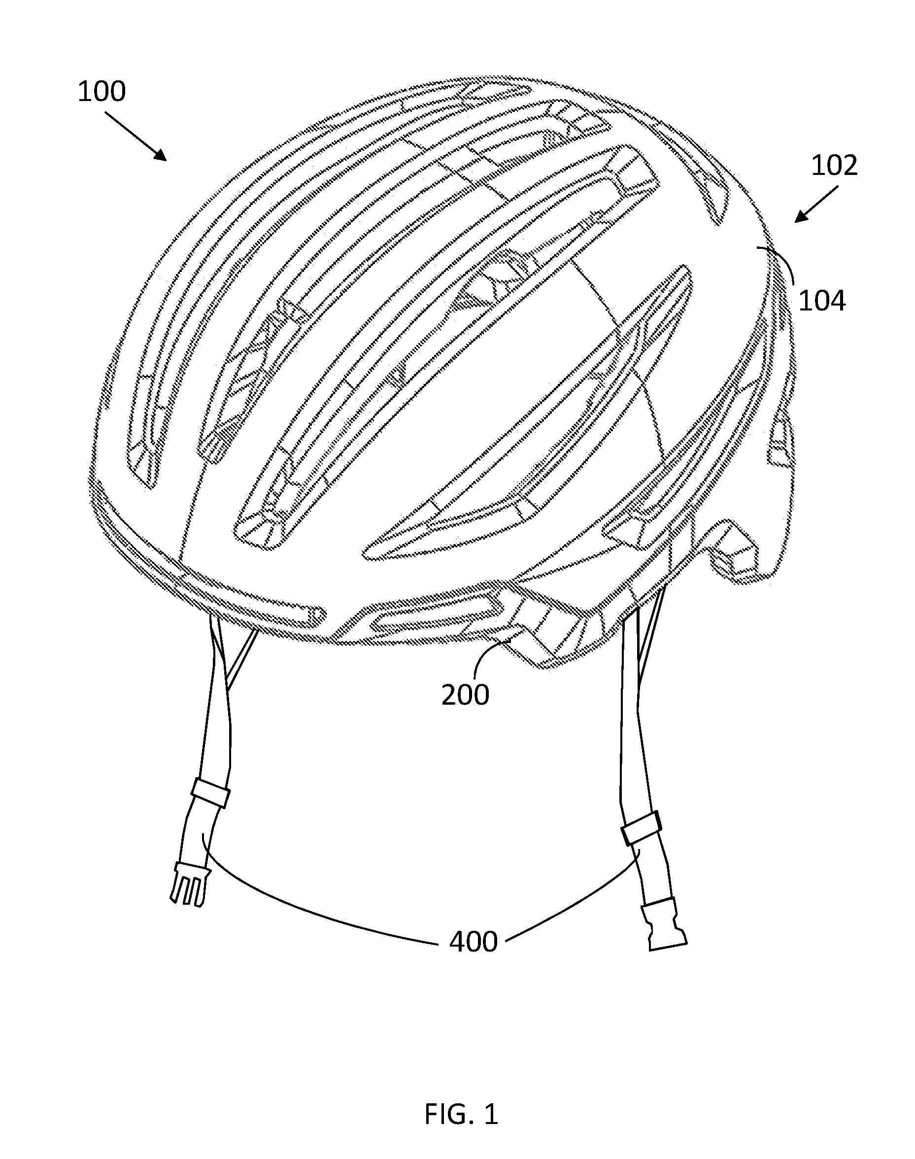
[0016] FIG. 1 is a perspective view of a multi-liner helmet;
[0017] FIG. 2 is a front perspective view of an energy management liner;
[0018] FIG. 3 is a cross-sectional side view of the energy management liner shown in FIG. 2, where the outer liner is shown as transparent;
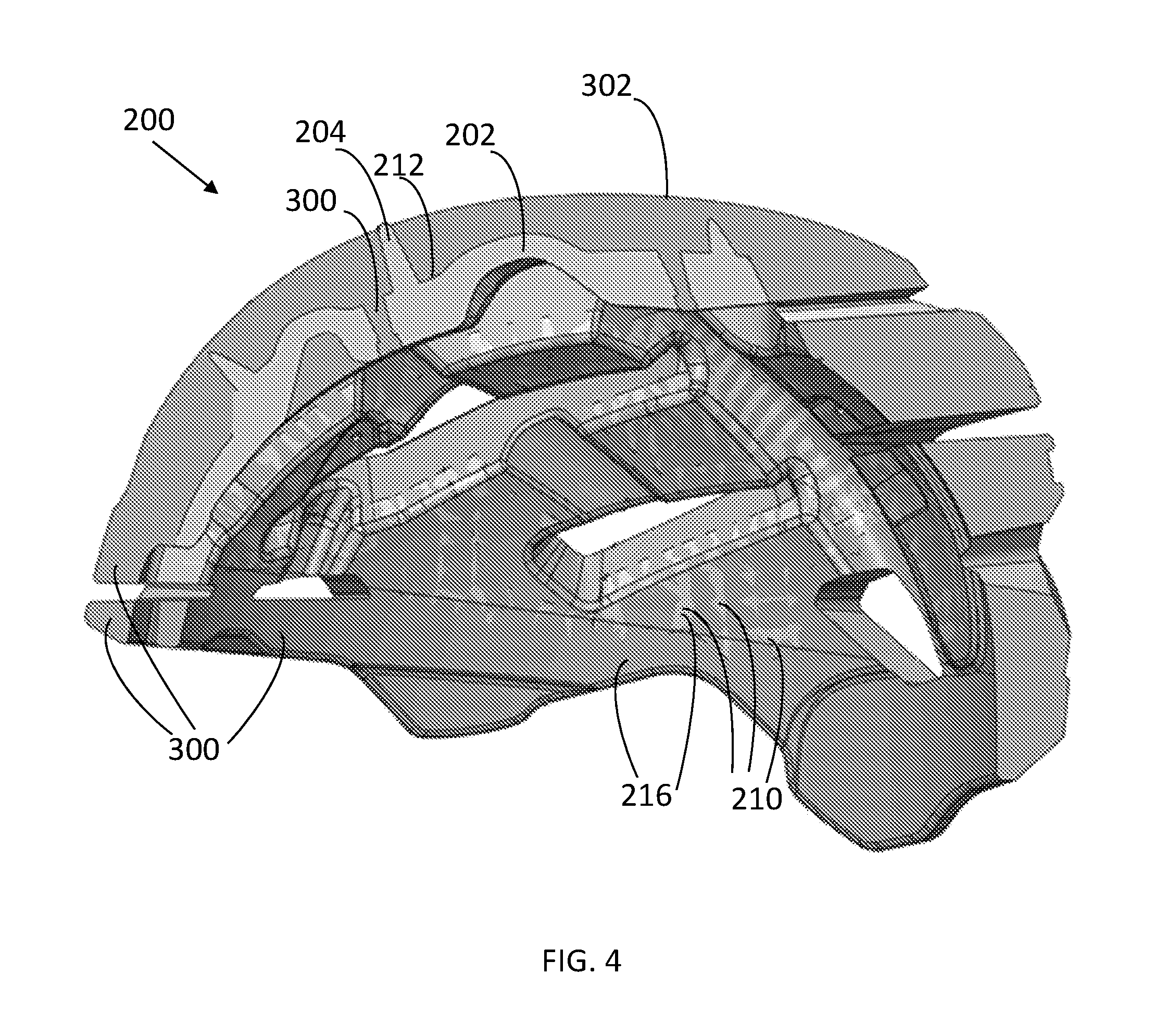
[0019] FIG. 4 is the cross-sectional side view of the energy management liner shown in FIG. 2, where the outer liner is shown as solid;
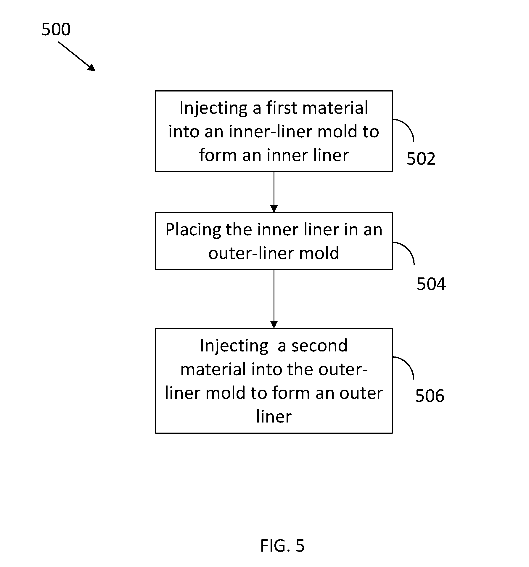
[0020] FIG. 5 is a flow chart of a method for assembling a multi-liner helmet.
DETAILED DESCRIPTION
[0021] While this disclosure includes embodiments in many different forms, they are shown in the drawings and will herein be described in detailed particular embodiments with the understanding that the present disclosure is to be considered as an exemplification of the principles of the disclosed methods and systems, and is not intended to limit the broad aspect of the disclosed concepts to the embodiments illustrated.
[0022] Protective head gear and helmets have been used in a wide variety of applications and across a number of industries including recreation, sports, athletics, construction, mining, military defense, and others, to prevent damage to users' heads and brains. Damage and injury to a user can be prevented or reduced by preventing hard objects, sharp objects, or both, from directly contacting the user's head, and also by absorbing, distributing, or otherwise managing energy of an impact between the object and the user's head. Straps or webbing are typically used to allow a user to releasably wear their helmet, and to ensure the helmet remains on the user's head during an impact.
[0023] Protective headgear or helmets can be used for a snow skier, a cyclist, football player, hockey player, baseball player, lacrosse player, polo player, climber, auto racer, motorcycle rider, motocross racer, snowboarder or other snow or water athlete, sky diver or any other athlete, recreational or professional, in a sport. Other non-athlete users such as workers involved in industry, including without limitation construction workers or other workers or persons in dangerous work environments can also benefit from the protective headgear described herein, as well as the system and method for providing the protective head gear.
[0024] Helmets function to provide protection while minimizing interference with an activity. The shape of a helmet may be adapted to provide both protection and comfort (e.g. ventilation, size, etc.). Some helmets are made of two or more bodies of energy-absorbing material formed in shapes that would be difficult, if not impossible, to achieve in a single molded piece.
[0025] Various implementations and embodiments of protective helmets according to this disclosure comprise a protective shell. The protective shell may be formed of an energy absorbing material such as expanded polystyrene (EPS), expanded polyurethane (EPU), expanded polyolefin (EPO), expanded polypropylene (EPP), or other suitable material. The energy absorbing material can be used as part of a hard-shell helmet such as skate bucket helmets, motorcycle helmets, snow sport helmets, football helmets, batting helmets, catcher's helmets, or hockey helmets, and include an additional outer protective shell disposed outside, or over, the protective shell. In hard shell applications, the energy absorbing material may comprise one or more layers of EPP and provide more flexibility. Alternatively, the energy absorbing material may be part of an in-molded helmet such as a bicycle helmet or cycling helmet. An outer shell layer, such as a layer of stamped polyethylene terephthalate or a polycarbonate shell, may be included on an outer surface of the protective shell of the helmet and be bonded directly to the energy management liner.
[0026] Contemplated as part of this disclosure is a multi-liner helmet having a co-molded energy management liner, as well as a method of assembling such a helmet.
[0027] A helmet 100 comprises a helmet body 102 (FIG. 1). A helmet 100 may further comprise a fit system 400. The helmet body 102 comprises an outer shell 104 and an in-molded or co-molded energy management liner, energy absorbing liner, or impact liner 200 inside the outer shell 104. The fit system 400 may be disposed within the in-molded energy management liner 200 and coupled to the helmet body 102.
[0028] The in-molded energy management liner 200 comprises an inner liner 202 and an outer liner 300 (FIGS. 2 and 3). In FIG. 3, the outer liner 300 is depicted as transparent to show the structure of the inner liner 202. The inner liner 202 and the outer liner 300 may be formed by molding. The inner liner 202 comprises an inside surface 210, an outside surface 212, and sides 214 connecting the inside surface 210 with the outside surface 212. The inner liner 202 comprises at least one hole 208 through the inner liner 202. The outer liner 300 may be formed around the inner liner 202 such that the outer liner 300 extends through the holes 208 and around at least two of the sides 214 of the inner liner 202, covering a majority of the outside surface 212 and at least a portion of the inside surface 210. In some embodiments, the outer liner 300 extends at least partially around all of the sides 214 of the inner liner 202. In some embodiments, both the inner liner 202 and the outer liner 300 are exposed on the inside 216 of the in-molded energy management liner 200 (FIG. 4). In FIG. 4, the inner liner 202 is depicted in light gray and the outer liner 300 is depicted in dark gray.
[0029] The inner liner 202 is made of a first material. The outer liner 300 is made of a second material. The first material and second materials may be different. The first and second materials may be of any types of material used to manage energy impact to the helmet 100. The first and second materials may be any types of material that can be expanded and, during the process of molding, formed into bigger objects. The pre-expanded materials are also called beads. For example, the first or second material may be EPS, EPP, EPU, or EPO. In some embodiments, the first material is EPP and the second material is EPS.
[0030] The inner liner may further comprise one or more standoffs 204. In some embodiments, the standoffs 204 extend outward through the outside surface 302 of the outer liner 300. For example, as shown in FIG. 2, the standoffs 204 can be seen extending outward through the outside surface 302 of the outer liner 300. The standoffs may extend from the sides of the inner liner through the sides of the outer liner (not shown). The standoffs help hold the inner liner in place inside an outer-liner mold when the second materials are injected, often at a high speed, into the outer liner mold. The inner liner may be held in place in an outer-liner mold through other methods or structures, such as adhesive tapes and hooks-and-loops fasteners.
[0031] To assemble a multi-liner helmet, a method 500 may be used (FIG. 5). Method 500 comprises injecting a first material into an inner-liner mold to form an inner liner (502), placing the inner liner in an out-liner mold (504), and injecting a second material different from the first material into the outer-liner mold to form an outer liner around the inner liner (506). The outer liner formed by the method 500 may extend through at least one hole in the inner liner and around at least two sides of the inner liner, covering a majority of an outside surface of the inner liner, and both the inner liner and the outer liner are exposed on an inside of an in-molded energy management liner comprising the inner liner and the outer liner. In some embodiments, the first material is EPP and the second material is EPS. In some embodiments, the inner-liner comprises one or more standoffs extending outward and injecting a second material further comprises injecting the second material such that the standoffs extend outward through an outside surface of the outer liner.
[0032] When the inner liner and the outer liner are made of different materials, such as having different densities or chemicals, the two materials may stay separate and not form a chemical bond under heat and pressure during molding. The holes 208 of the inner liner 202 allow the second material for the outer liner to flow through and accumulate on the inside surface 210 of the inner liner 202 (FIGS. 3 and 4). As a result, the outer liner 300 is formed around, through, and under the inner liner 202 during the molding, and the two liners 202 and 300 are interlocked and held together by mechanical forces. No additional manufacturing parts or steps are required to hold the liners in the energy management liner together. Because the liners in the energy management liner are co-molded, the multi-liner helmets made in this manner are also more compact and lighter than those manufactured with a conventional method. Further, the design of the liners, such as the geometries of the liners, is not constrained by the fastening components used to fasten them together and, thus, more design freedom is provided.
[0033] This disclosure, its aspects and implementations, are not limited to the specific components or assembly procedures disclosed herein. Many additional components and assembly procedures known in the art consistent with the intended helmets, co-molded energy management liners, and methods of assembling a multi-liner helmet will become apparent for use with implementations of the apparatus and methods in this disclosure. In places where the description above refers to particular implementations of protective helmets, it should be readily apparent that a number of modifications may be made without departing from the spirit thereof and that these implementations may be applied to other protective helmets. The presently disclosed implementations are, therefore, to be considered in all respects as illustrative and not restrictive, the scope of the disclosure being indicated by the appended claims rather than the foregoing description. All changes that come within the meaning of and range of equivalency of the description are intended to be embraced therein. Accordingly, for example, although particular helmets, co-molded energy management liners, and methods of assembling a helmet are disclosed, such apparatus, methods, and implementing components may comprise any shape, size, style, type, model, version, class, grade, measurement, concentration, material, quantity, the like as is known in the art for such apparatus, methods, and implementing components, and/or the like consistent with the intended operation of the helmet, co-molded energy management liners, and methods of assembling a helmet may be used.
[0034] The word "exemplary," "example," or various forms thereof are used herein to mean serving as an example, instance, or illustration. Any aspect or design described herein as "exemplary" or as an "example" is not necessarily to be construed as preferred or advantageous over other aspects or designs. Furthermore, examples are provided solely for purposes of clarity and understanding and are not meant to limit or restrict the disclosed subject matter or relevant portions of this disclosure in any manner. It is to be appreciated that a myriad of additional or alternate examples of varying scope could have been presented, but have been omitted for purposes of brevity.
* * * * *
D00000
D00001
D00002
D00003
D00004
D00005
XML
uspto.report is an independent third-party trademark research tool that is not affiliated, endorsed, or sponsored by the United States Patent and Trademark Office (USPTO) or any other governmental organization. The information provided by uspto.report is based on publicly available data at the time of writing and is intended for informational purposes only.
While we strive to provide accurate and up-to-date information, we do not guarantee the accuracy, completeness, reliability, or suitability of the information displayed on this site. The use of this site is at your own risk. Any reliance you place on such information is therefore strictly at your own risk.
All official trademark data, including owner information, should be verified by visiting the official USPTO website at www.uspto.gov. This site is not intended to replace professional legal advice and should not be used as a substitute for consulting with a legal professional who is knowledgeable about trademark law.