Bump Cap
Votel; Thomas ; et al.
U.S. patent application number 15/810133 was filed with the patent office on 2019-03-28 for bump cap. The applicant listed for this patent is Tenacious Holdings, Inc.. Invention is credited to Andrew Olson, Jeffrey Popowski, Gregory Schrab, Thomas Votel.
| Application Number | 20190090573 15/810133 |
| Document ID | / |
| Family ID | 65806529 |
| Filed Date | 2019-03-28 |


| United States Patent Application | 20190090573 |
| Kind Code | A1 |
| Votel; Thomas ; et al. | March 28, 2019 |
BUMP CAP
Abstract
The presented invention is an adjustable protective Bump Cap to be worn under a hat. The Bump Cap has adjustable horizontal and vertical dimensions to enable a secure fit and to remain out of sight when worn under a user's hat.
| Inventors: | Votel; Thomas; (Sunfish Lake, MN) ; Olson; Andrew; (Minneapolis, MN) ; Popowski; Jeffrey; (Roseville, MN) ; Schrab; Gregory; (Shoreview, MN) | ||||||||||
| Applicant: |
|
||||||||||
|---|---|---|---|---|---|---|---|---|---|---|---|
| Family ID: | 65806529 | ||||||||||
| Appl. No.: | 15/810133 | ||||||||||
| Filed: | November 12, 2017 |
Related U.S. Patent Documents
| Application Number | Filing Date | Patent Number | ||
|---|---|---|---|---|
| 29619071 | Sep 26, 2017 | |||
| 15810133 | ||||
| Current U.S. Class: | 1/1 |
| Current CPC Class: | A42B 3/06 20130101; A42B 1/08 20130101 |
| International Class: | A42B 3/06 20060101 A42B003/06 |
Claims
1. A Bump Cap to be worn under a hat comprising: a rigid skull shaped shell having a right side portion, a left side portion, a crown portion, a visor portion and a rear flap portion; a vent located in the right side portion; a vent located in the left side portion; a vent located in the crown portion; a flexible joint located between the visor portion and the left side portion; a flexible joint located between the visor portion and the right side portion; a flexible joint located between the right side portion and the rear flap portion; a flexible joint located between the left side portion and the rear flap portion; a trim groove, to allow for removal of a portion of the shell, located on a lower parameter of the left side portion; and, a trim groove located on a lower parameter of the right side portion.
2. The Bump Cap of claim 1 wherein the vents located in the left and right side portions are elongated and configured horizontally.
3. The Bump Cap of claim 1 wherein the trim grooves have adjacent trim notches.
4. A Bump Cap to be worn under a hat comprising: a rigid shell having a visor portion, a crown portion, a left side portion and a right side portion; a flexible joint located between the visor portion and the right side portion; a flexible joint located between the visor portion and the left side portion; a trim groove located on the left side portion; a trim groove located on the right side portion; and, whereas the vertical dimension of the shell maybe adjusted by removing a portion of the shell at the trim groove.
5. The bump cap of claim 4 wherein a vent is located on the crown portion.
Description
CLAIM OF BENEFIT TO PRIOR APPLICATIONS
[0001] This application is a continuation-in-part of U.S. Design Application No. 29/619,071 filed Sep. 26, 2017; and such application is hereby fully incorporated by reference herein.
FIELD
[0002] The present invention relates generally to protective headwear. More particularly, the present invention relates to an adjustable Bump Cap.
BACKGROUND
[0003] Bump Caps are useful for protecting the wearer's head from bumps, cuts and bruises as a result of contact with objects such as overhead pipes, low ceilings and other objects. They are most often worn under a personal hat, uniform cap, baseball hat or other non-protective headwear.
[0004] There are many different types of non-protective headwear, such as the so-called trucker's hat, which tends to be of a taller dimension, and a variety of baseball type hats that can be structured, unstructured, low profile and higher profile. There are also a variety of other personal hats, such as Trilby, Fedora, bucket, cowboy and stocking hats. Because of the variable dimensions of these hats there is a current and unfulfilled need for a Bump Cap that can be adjusted to accommodate the various hat dimensions.
SUMMARY
[0005] The invention provides a Bump Cap to be worn under a variety of hats that can be flexible to allow for horizontal variations in hat dimensions, and trimable to allow for variation in the vertical variations in hat dimensions.
[0006] This summary is not intended to limit the scope of the invention, or describe each embodiment, implementation, feature or advantage of the invention.
BRIEF DESCRIPTION OF THE DRAWINGS
[0007] FIG. 1 is a front perspective view of a preferred embodiment of the invention.
[0008] FIG. 2 is a rear perspective view of a preferred embodiment of the invention.
[0009] FIG. 3 is a front elevation of a preferred embodiment of the invention.
[0010] FIG. 4 is a rear elevation of a preferred embodiment of the invention.
[0011] FIG. 5 is right side elevation view of a preferred embodiment of the invention.
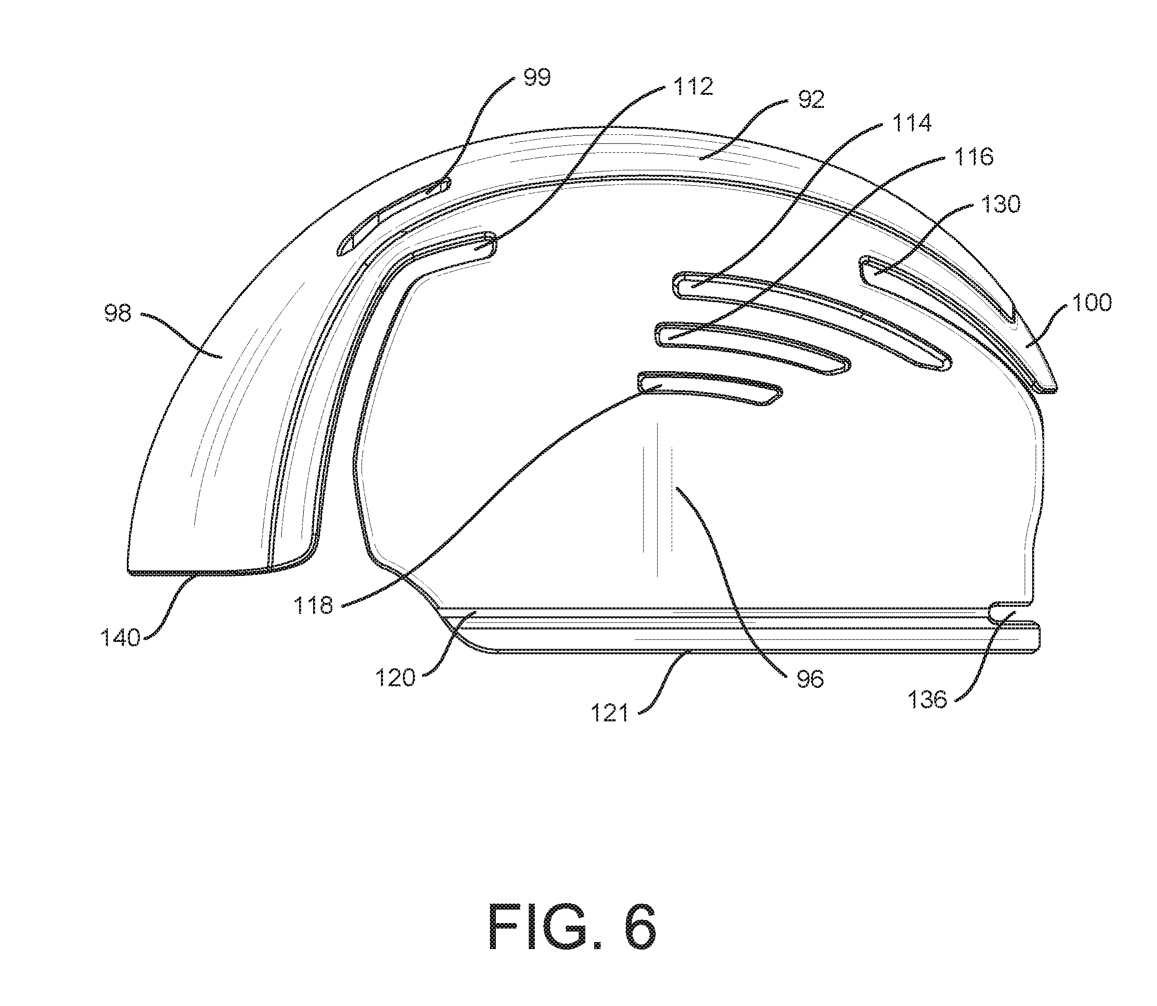
[0012] FIG. 6 is a left side elevation view of a preferred embodiment of the invention.
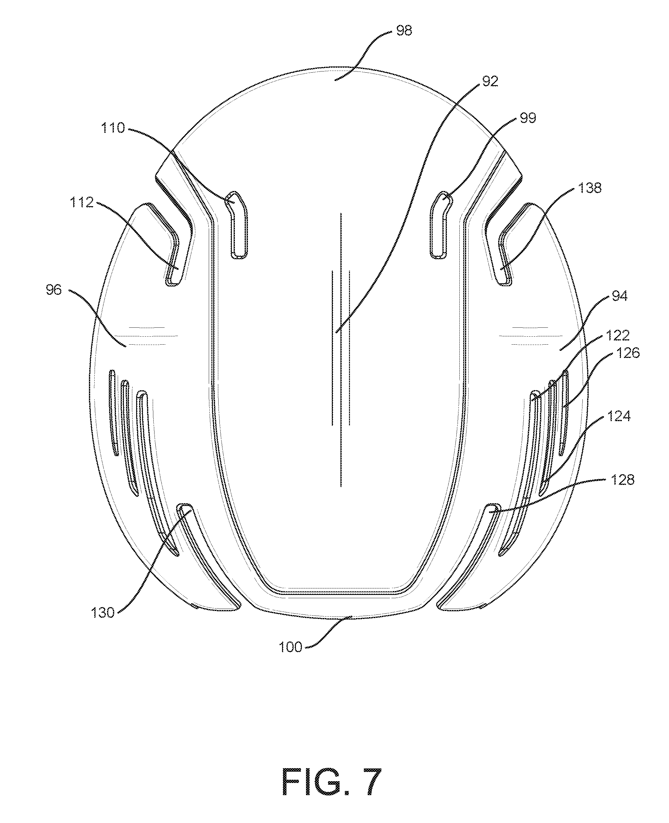
[0013] FIG. 7 is a top plan view of a preferred embodiment of the invention.
DESCRIPTION OF THE PREFERRED EMBODIMENTS
[0014] It will be apparent to those skilled in the art, that is, to those who have knowledge or experience in this area of technology, which many uses and design variations are possible for the adjustable Bump Cap disclosed herein. The following detailed discussion of the preferred embodiment will illustrate the general principles of the invention with reference to the disclosed Bump Cap. Other embodiments suitable for other applications will be apparent to those skilled in the art given the benefit of this disclosure.
[0015] The Bump Cap is preferably injection molded from a thermoplastic polymer such as polypropylene. Those skilled in the art will recognize that other rigid materials that have at least some flexibility may also be used.
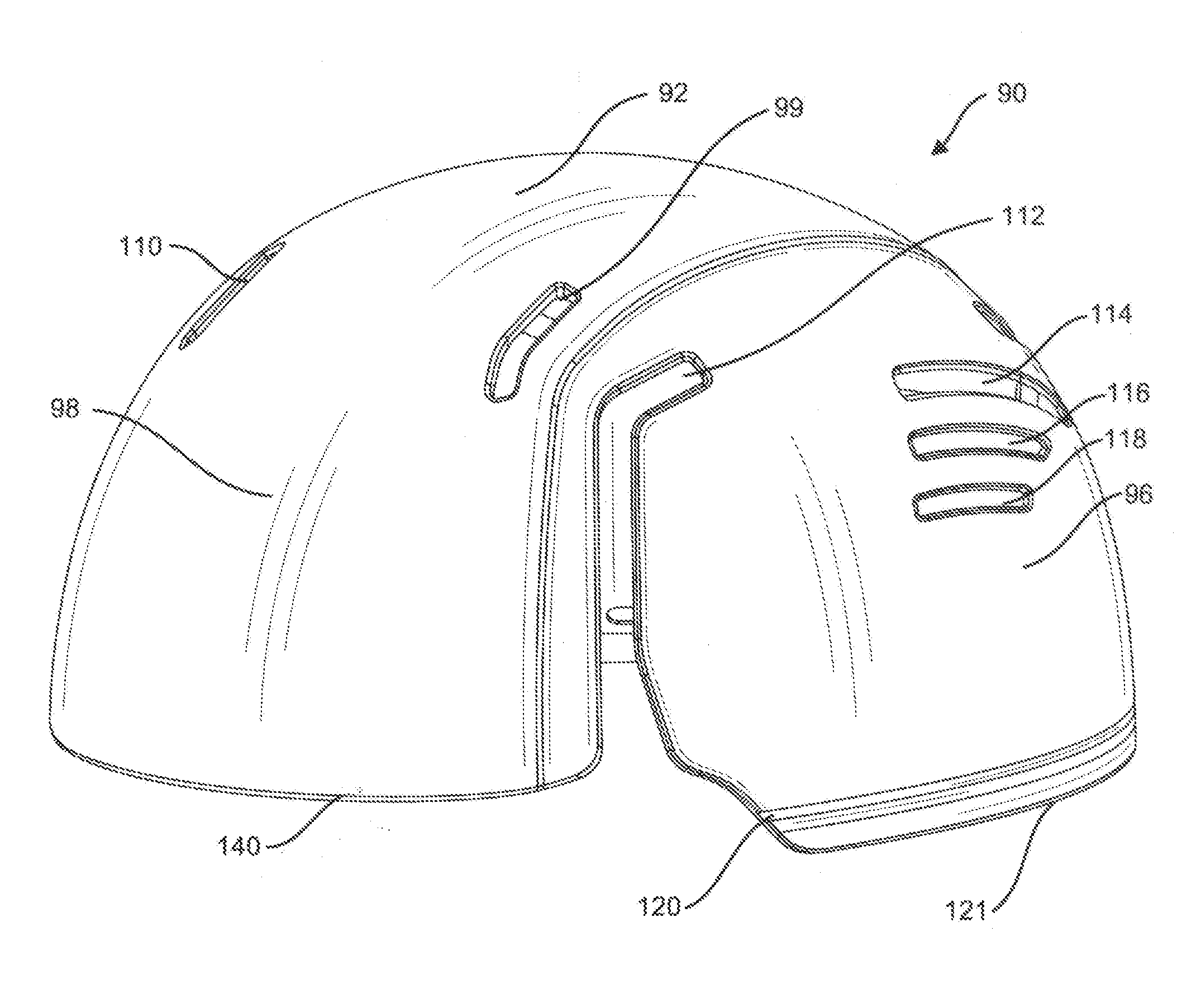
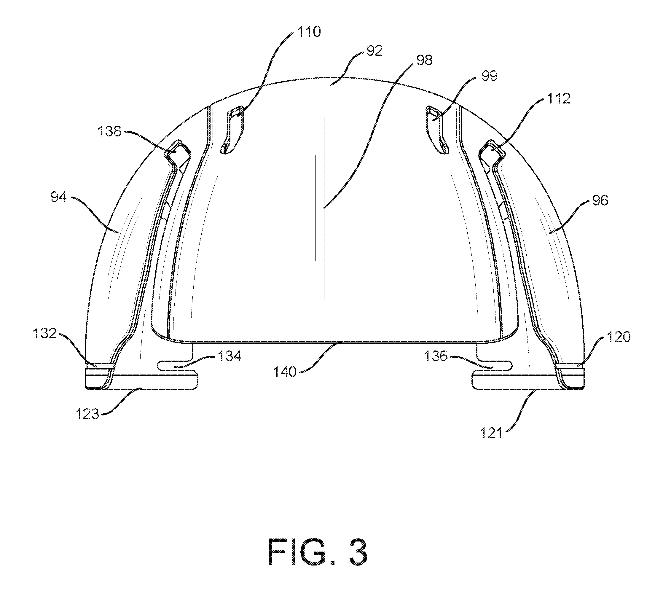
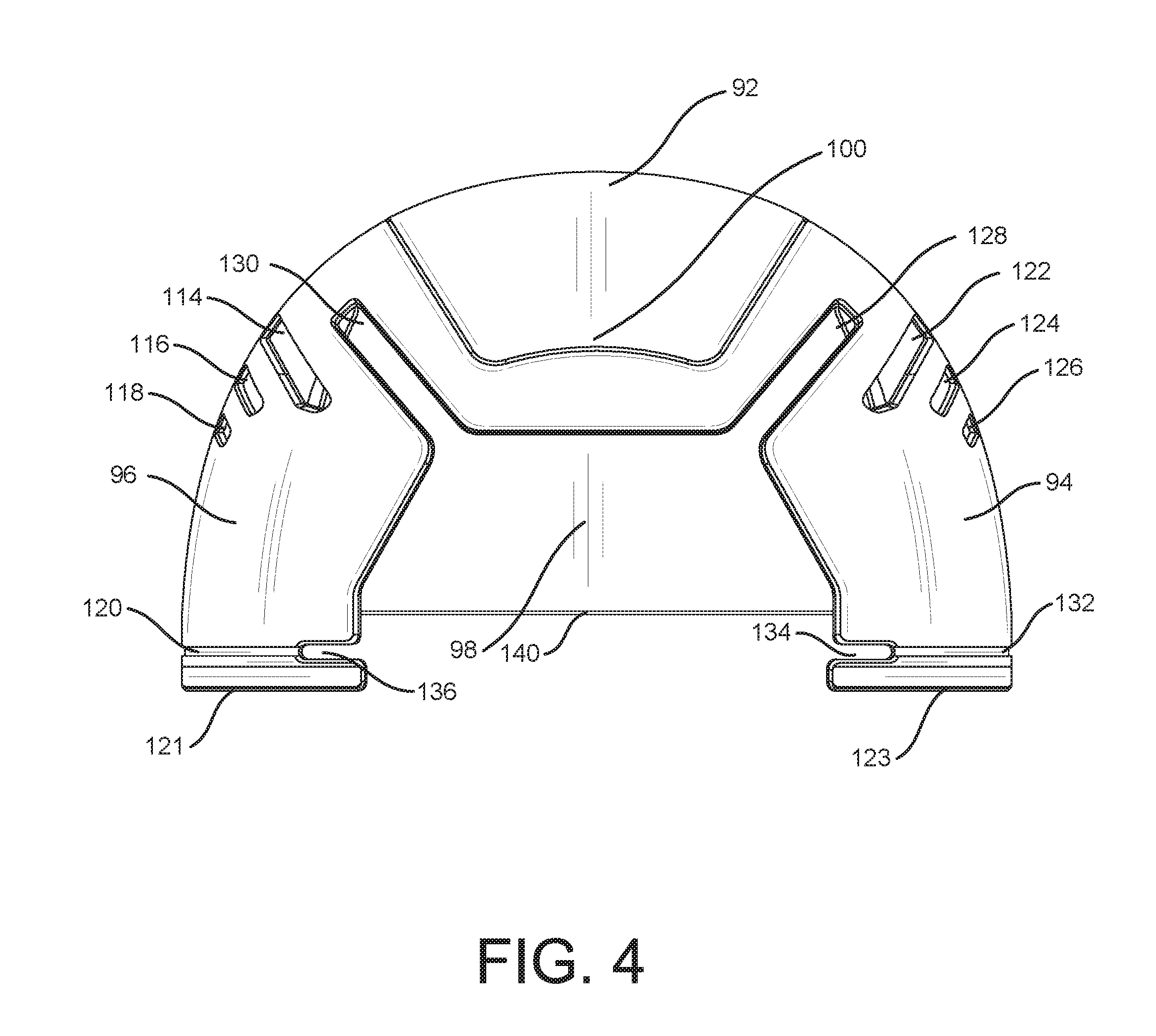
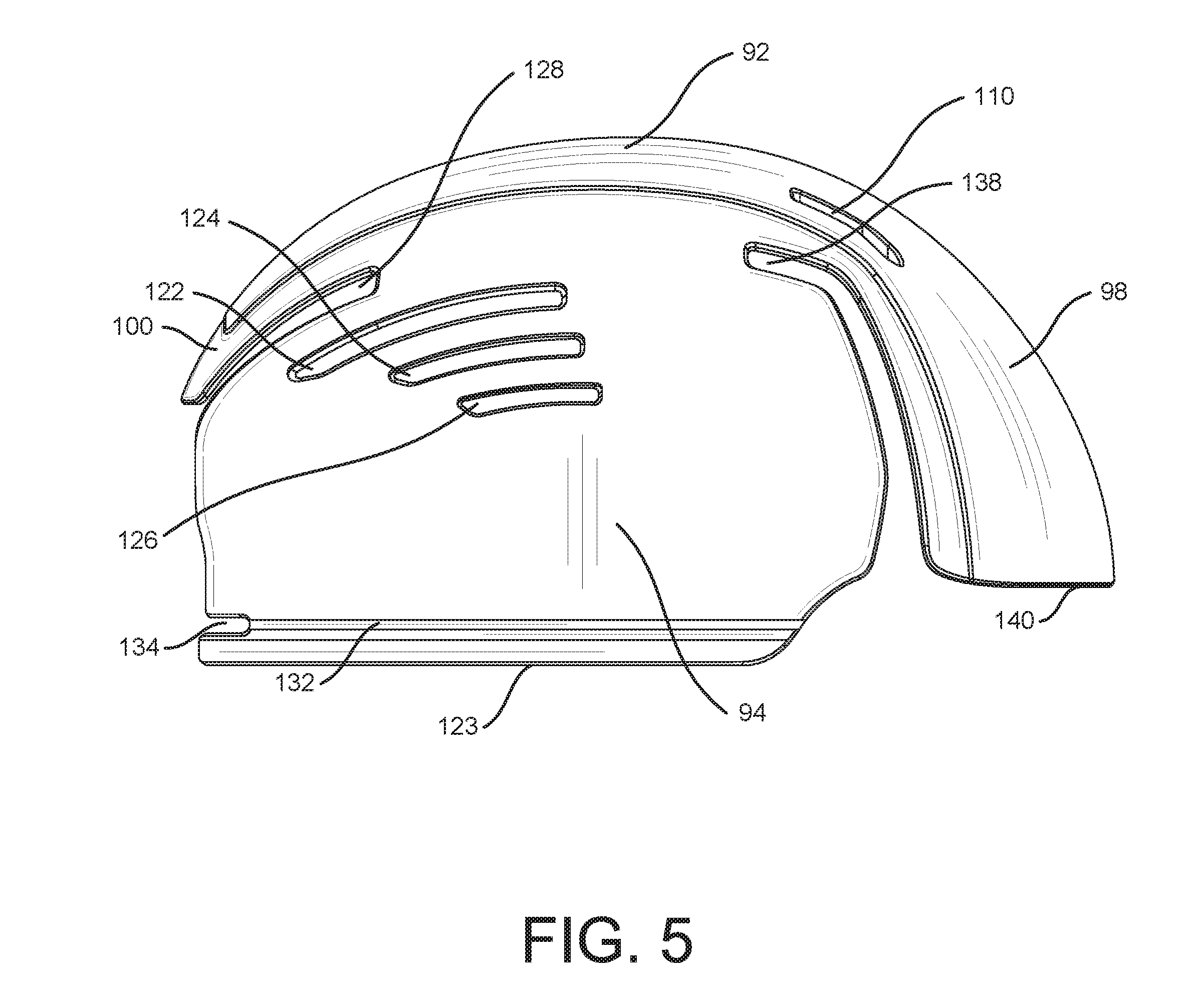
[0016] With reference to FIGS. 1-7, the various features of Bump Cap 90 are shown. Bump Cap 90 is comprised of crown 92 right side portion 94, left side portion 96, visor portion 98 and rear flap portion 100. Vents 114, 116 and 118 provide left side portion 96 ventilation, whereas vents 122, 124 and 126 provide right side portion 94 ventilation. Vents 110 and 99 provide crown 92 ventilation. One skilled in the art will understand that more or fewer vents may be required, and placement may be varied, according to environmental conditions or users' requirements.
[0017] Flex joints 138, 112, 128 and 130 allow Bump Cap 90 to flex when inserted into a hat to allow for variations in the hat's horizontal dimensions and to aide it securing Bump Cap 90 in place. Flex joints 138, 112, 128 and 130 also may supply additional ventilation.
[0018] Trim grooves 120 and 132 are located on the lower perimeter 121 of left side portion 96 and lower perimeter 123 on right side portion 94. Trim groove 120 runs horizontally along lower perimeter 121 on the left side portion 96. Trim groove 132 runs horizontally along lower perimeter 123 on right side portion 94. Trim grooves 120 and 132 allow sections of Bump Cap 90 to be removed by hand, box knife, scissors or other means. Removal of sections of Bump Cap 90 via trim grooves 120 and 132 allow the vertical dimensions of Bump Cap 90 to be adjusted so as to remain secure and hidden under a user's hat. One skilled in the art will appreciate that more than one trim groove may be incorporated into Bump Cap 90 to allow for greater vertical dimension adjustment.
[0019] Trim notches 134 and 136 assist the user in removing a portion of Bump Cap 90 at the trim groves 120 and 132. More trim notches may be used to accommodate a greater number of trim grooves. Trim grooves and respective trim notches may also be incorporated into leading edge 140 of visor portion 98 to allow for the vertical adjustment of visor portion 98 (grooves not shown).
[0020] While the invention has been described in connection with what is presently considered to be the most practical and preferred embodiments, it will be apparent to those of ordinary skill in the art that the invention is not to be limited to the disclosed embodiments. It will be readily apparent to those of ordinary skill in the art that many modifications and equivalent arrangements can be made thereof without departing from the spirit and scope of the present disclosure, such scope to be accorded the broadest interpretation of the appended claims so as to encompass all equivalent structures and products. Moreover, features or aspects of various example embodiments may be mixed and matched (even if such combination is not explicitly described herein) without departing from the scope of the invention.
[0021] For purposes of interpreting the claims for the present invention, it is expressly intended that the provisions of Section 112, sixth paragraph of 35 U.S.C. are not to be invoked unless the specific terms "means for" or "step for" are recited in a claim.
* * * * *
D00000
D00001
D00002
D00003
D00004
D00005
D00006
D00007
XML
uspto.report is an independent third-party trademark research tool that is not affiliated, endorsed, or sponsored by the United States Patent and Trademark Office (USPTO) or any other governmental organization. The information provided by uspto.report is based on publicly available data at the time of writing and is intended for informational purposes only.
While we strive to provide accurate and up-to-date information, we do not guarantee the accuracy, completeness, reliability, or suitability of the information displayed on this site. The use of this site is at your own risk. Any reliance you place on such information is therefore strictly at your own risk.
All official trademark data, including owner information, should be verified by visiting the official USPTO website at www.uspto.gov. This site is not intended to replace professional legal advice and should not be used as a substitute for consulting with a legal professional who is knowledgeable about trademark law.