Winter Headwear With Bump Cap
Votel; Thomas ; et al.
U.S. patent application number 16/119981 was filed with the patent office on 2019-03-28 for winter headwear with bump cap. The applicant listed for this patent is Tenacious Holdings, Inc.. Invention is credited to Dominique Aris, Alsie Nelson, Thomas Votel.
| Application Number | 20190090568 16/119981 |
| Document ID | / |
| Family ID | 65806341 |
| Filed Date | 2019-03-28 |


View All Diagrams
| United States Patent Application | 20190090568 |
| Kind Code | A1 |
| Votel; Thomas ; et al. | March 28, 2019 |
WINTER HEADWEAR WITH BUMP CAP
Abstract
The presented invention is an item of winter headwear that is configured to accept a protective and removable bump cap.
| Inventors: | Votel; Thomas; (Sunfish Lake, MN) ; Nelson; Alsie; (Woodbury, MN) ; Aris; Dominique; (Edina, MN) | ||||||||||
| Applicant: |
|
||||||||||
|---|---|---|---|---|---|---|---|---|---|---|---|
| Family ID: | 65806341 | ||||||||||
| Appl. No.: | 16/119981 | ||||||||||
| Filed: | August 31, 2018 |
Related U.S. Patent Documents
| Application Number | Filing Date | Patent Number | ||
|---|---|---|---|---|
| 29619071 | Sep 26, 2017 | |||
| 16119981 | ||||
| Current U.S. Class: | 1/1 |
| Current CPC Class: | A42B 1/066 20130101; A42B 7/00 20130101; A42B 3/06 20130101; A42B 3/08 20130101; A42B 1/08 20130101 |
| International Class: | A42B 1/08 20060101 A42B001/08; A42B 3/06 20060101 A42B003/06; A42B 3/08 20060101 A42B003/08; A42B 7/00 20060101 A42B007/00 |
Claims
1. Winter headwear with insertable bump cap comprising: an item of winter headwear comprising a crown portion having a first layer and a second layer defining an opening therebetween; an access section located on the first layer of the crown portion of the winter headwear, the access section having an open position and a closed position; the first layer of the winter headwear crown portion being laid open when the access section is in its open position; a bump cap sized such that it can be inserted into the opening between the first layer and the second layer of the crown portion when the access section is in its open position; the bump cap further being sized and configured to allow the bump cap to remain in the opening between the first layer and the second layer of the crown portion of the winter headwear when the access section is in its closed position; the bump cap comprising a skull shaped shell having a rigid outer surface; the skull shaped shell being sized to fit over the skull of a the wearer of the winter headwear; and, wherein the rigid outer surface of the bump cap defines at least two vent openings.
2. The winter headwear with insertable bump cap of claim 1 wherein the access section is a zipper.
3. The winter headwear with insertable bump cap of claim 1 wherein the at least two vent openings are located on a left side portion and a right side portion of the rigid outer shell of the skull portion of the bump cap.
4. The winter headwear with insertable bump cap of claim 1 wherein a trim groove, to allow for removal of a portion of the bump cap shell, is located on a lower perimeter of the bump cap.
5. A method of inserting a bump cap into winter headwear, the method comprising: placing a zipper on a crown of an item of winter headwear in an open position such that an upper layer of the crown is laid open, the winter head wear comprising a front facing portion and a rear portion; inserting a skull shaped bump cap that has a rigid outer surface, a front portion and a rear portion, into the opening in the upper layer of the crown; orienting the skull shaped bump cap such that the front portion of the skull shaped bump cap is aligned with the front portion of the item of winter headwear; closing the zipper such that the entirety of the skull shaped bump cap is enclosed and under the upper layer of the crown of the item of winter headwear.
6. The method of claim 4 further comprising: trimming a lower perimeter section of the skull shaped bump cap on a trim groove to alter the shape of the skull shaped bump cap.
Description
CLAIM OF BENEFIT TO PRIOR APPLICATIONS
[0001] This application is a continuation-in-part of U.S. Design application No. 29/619,071 filed Sep. 26, 2017; and such application is hereby fully incorporated by reference herein.
FIELD
[0002] The present invention relates generally to protective headwear. More particularly, the present invention relates to a Bump Cap that can be removably inserted into cold weather headwear.
BACKGROUND
[0003] Bump Caps are useful for protecting the wearer's head from bumps, cuts and bruises as a result of contact with objects such as overhead pipes, low ceilings and other objects. They are most often worn under a personal hat, uniform cap, baseball hat or other non-protective headwear.
[0004] There are many different types of non-protective cold weather headwear, such as, for example, the watch cap, the trappers hat, the bomber hat, the fudd hat, and the balaclava hat, to name a few. Because a bump cap is many times required when the environmental conditions also require bulky headwear be worn to stay warm, there is a current and unfulfilled need to removably but securely combine the two articles. Further, because of the variable dimensions of these hats, there is a current and unfulfilled need for a Bump Cap that can be adjusted to accommodate the various hat dimensions.
SUMMARY
[0005] The invention provides a Bump Cap to be worn securely and removably in variety of cold weather hats, that can also be flexible to allow for horizontal variations in hat dimensions, and trimable to allow for variation in the vertical variations in hat dimensions.
[0006] This summary is not intended to limit the scope of the invention, or describe each embodiment, implementation, feature or advantage of the invention.
BRIEF DESCRIPTION OF THE DRAWINGS
[0007] FIG. 1 is a front perspective view of a preferred embodiment of the invention.
[0008] FIG. 2 is a rear perspective view of a preferred embodiment of the invention.
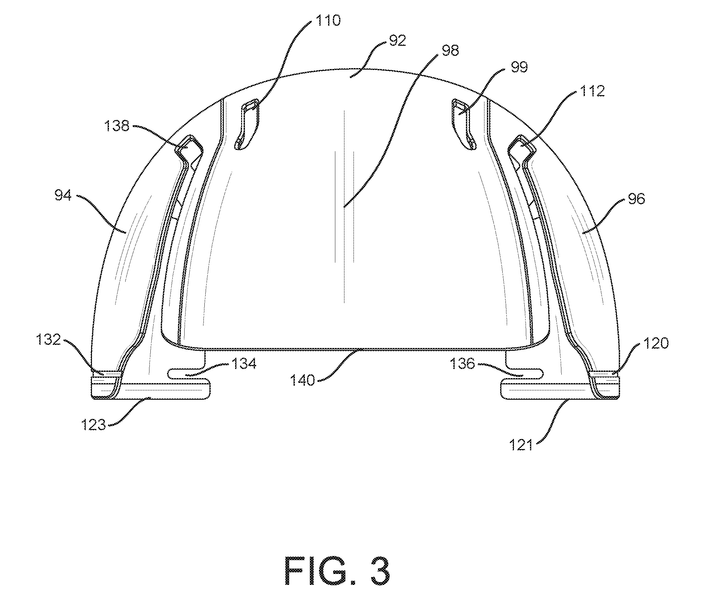
[0009] FIG. 3 is a front elevation of a preferred embodiment of the invention.
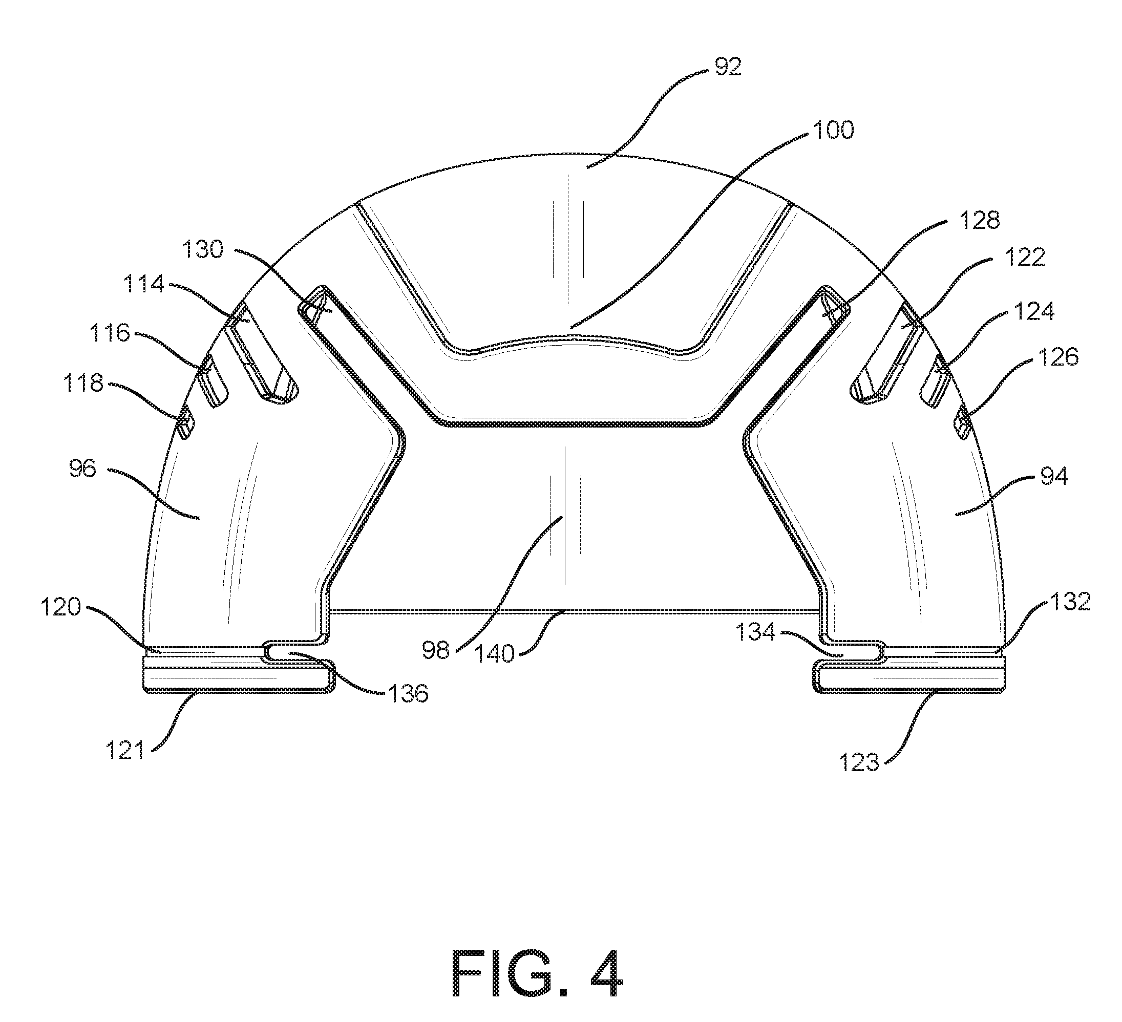
[0010] FIG. 4 is a rear elevation of a preferred embodiment of the invention.
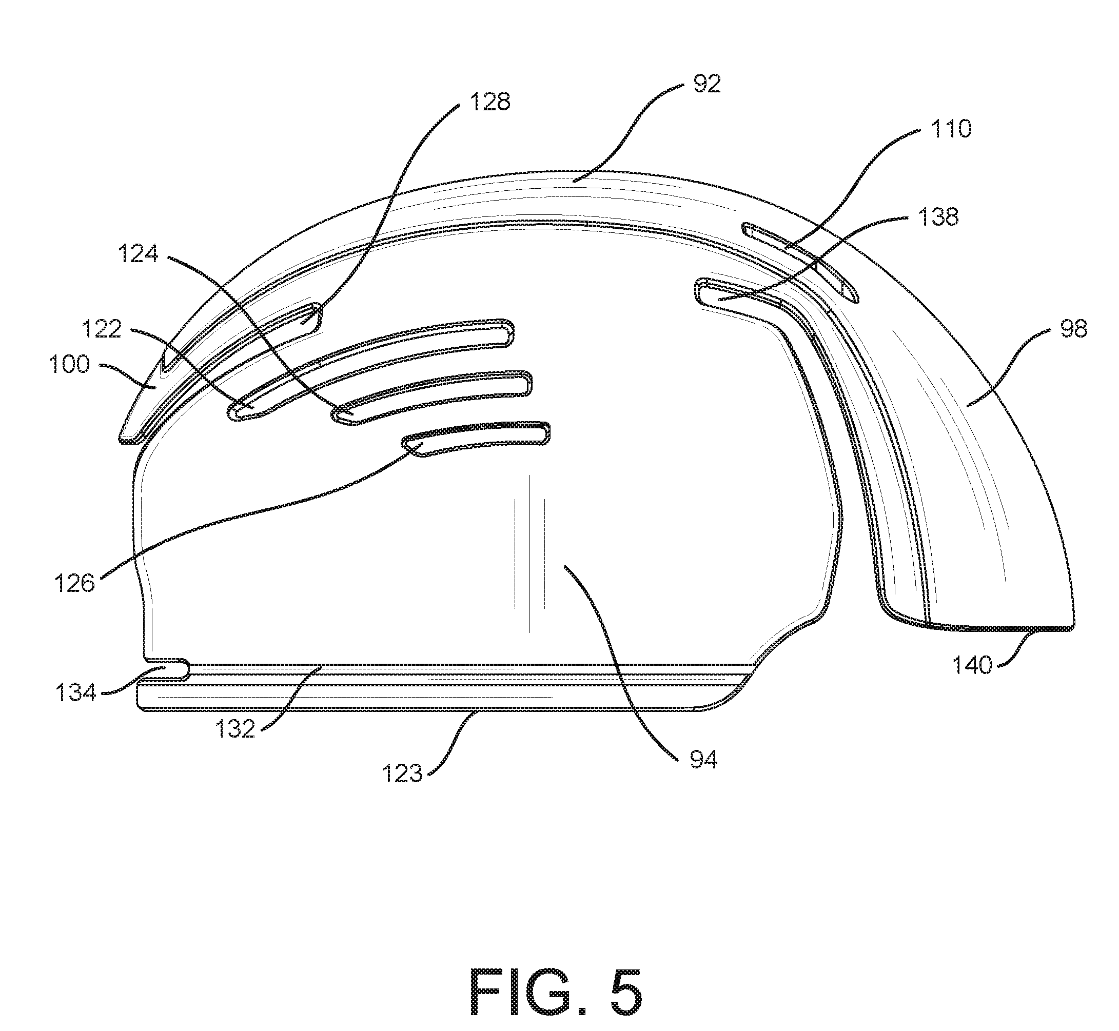
[0011] FIG. 5 is right side elevation view of a preferred embodiment of the invention.
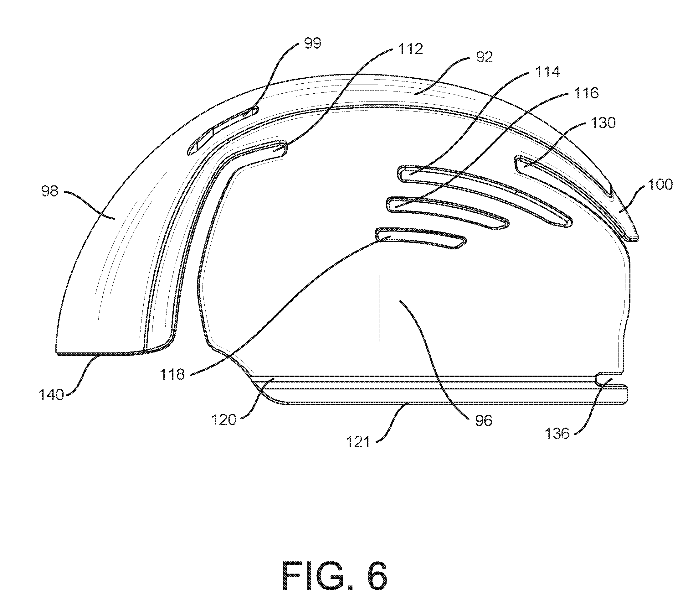
[0012] FIG. 6 is a left side elevation view of a preferred embodiment of the invention.
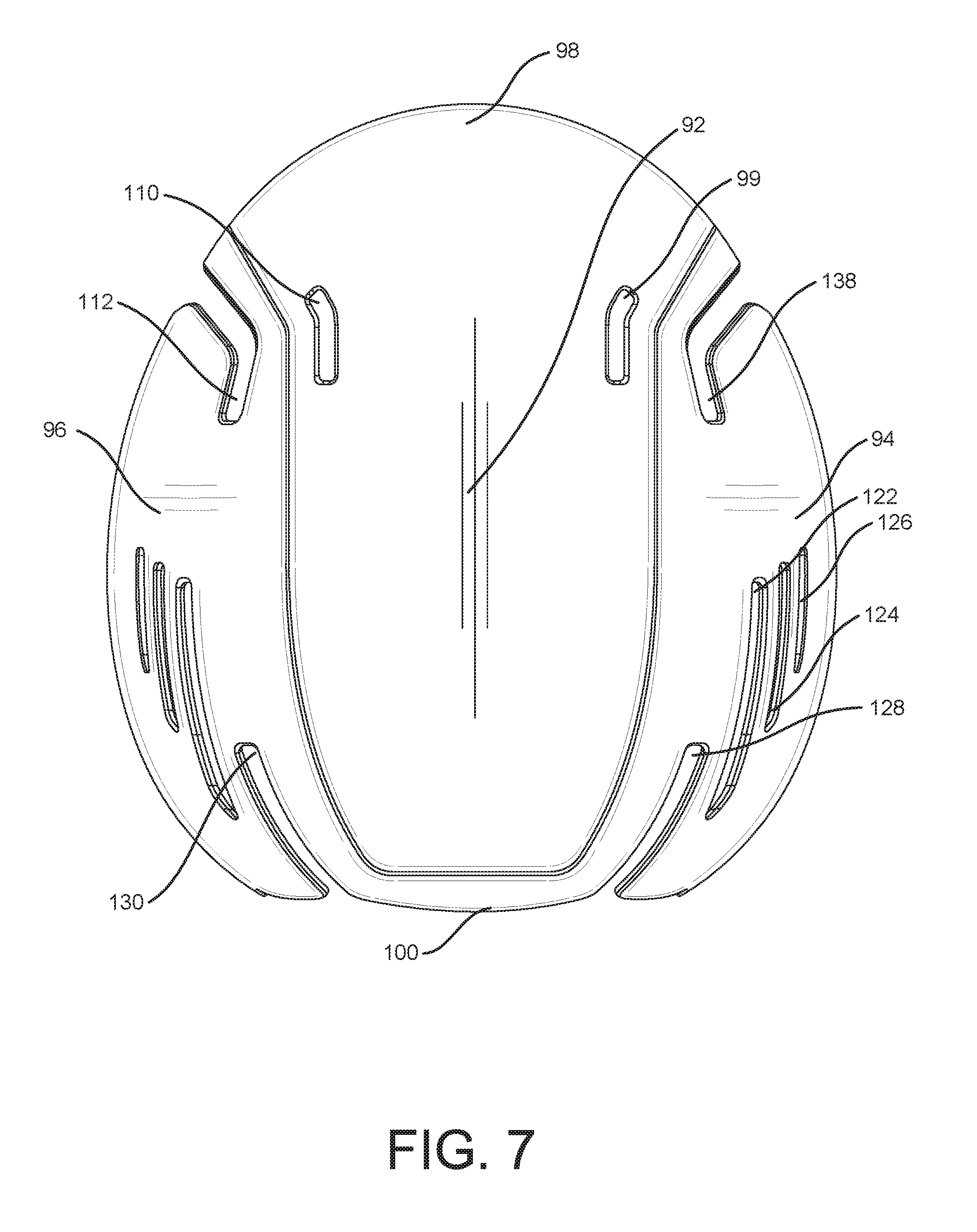
[0013] FIG. 7 is a top plan view of a preferred embodiment of the invention.
[0014] FIG. 8 is front elevation view showing exemplary winter headwear with the covered zipper closed.
[0015] FIG. 9 is a perspective view of a bump cap that is insertable into winter headwear.
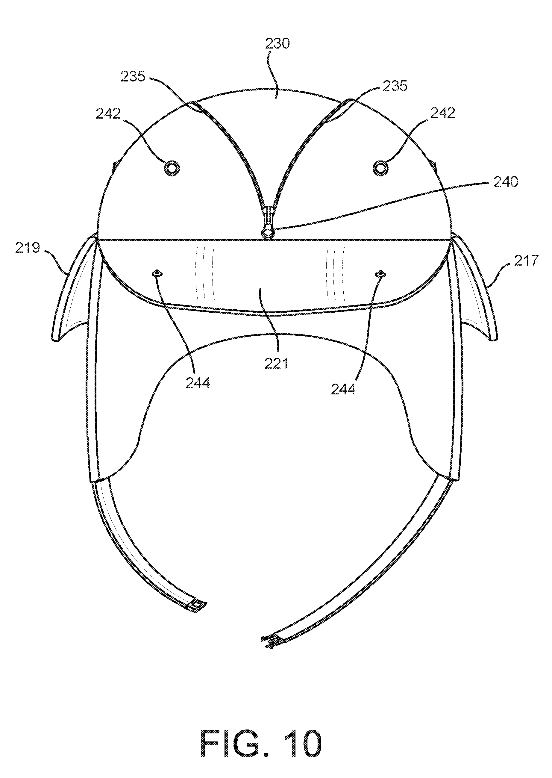
[0016] FIG. 10 is a front elevation view of exemplary winter headwear with the zipper in the open position revealing the insertable bump cap.
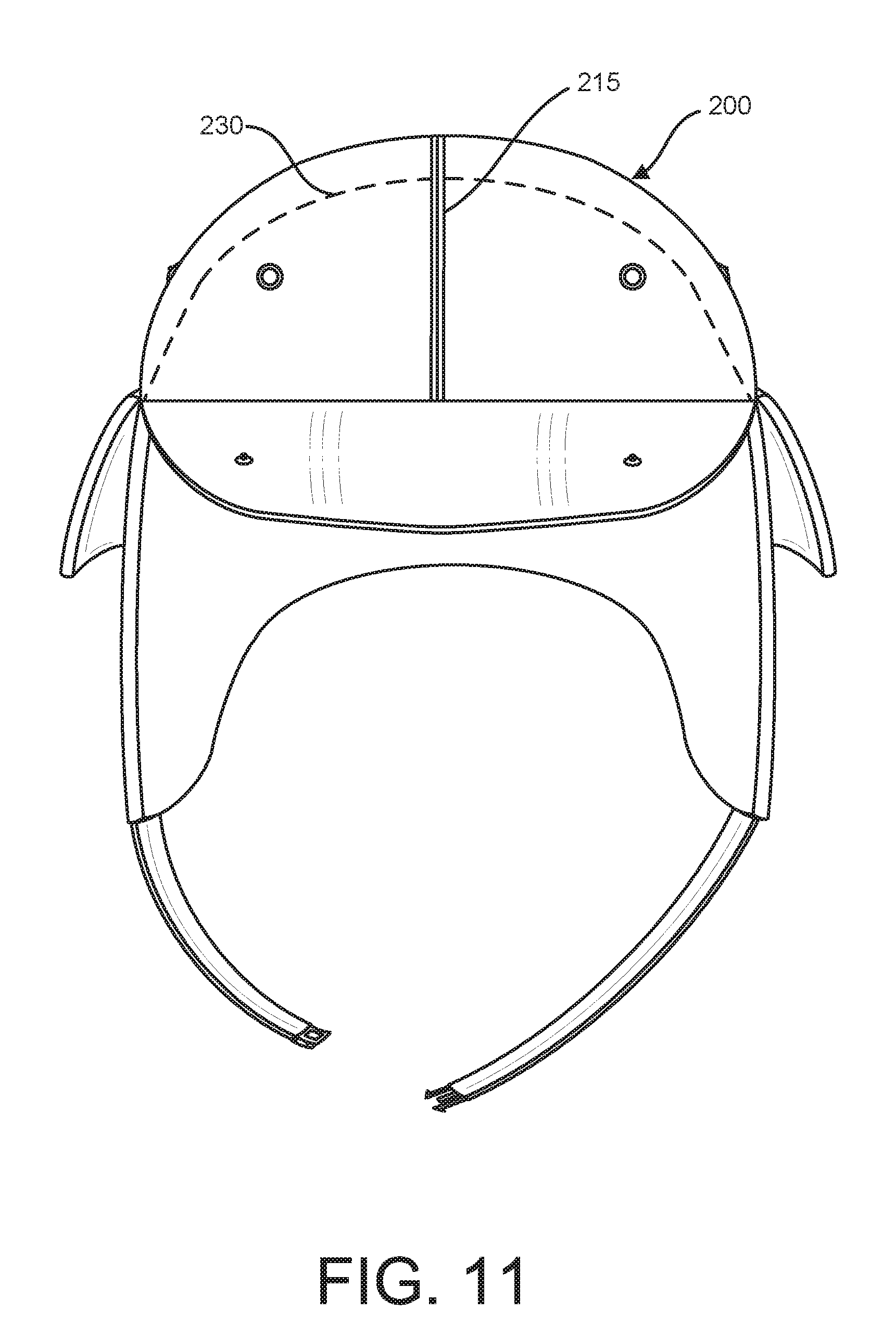
[0017] FIG. 11 is a front elevation view of exemplary winter headwear with the covered zipper in the closed position and the insertable bump cap shown in dashed lines.
DESCRIPTION OF THE PREFERRED EMBODIMENTS
[0018] It will be apparent to those skilled in the art, that is, to those who have knowledge or experience in this area of technology, which many uses and design variations are possible for the insertable, removable and adjustable Bump Cap disclosed herein. The following detailed discussion of the preferred embodiment will illustrate the general principles of the invention with reference to the disclosed Bump Cap. Other embodiments suitable for other applications will be apparent to those skilled in the art given the benefit of this disclosure.
[0019] The Bump Cap is preferably injection molded from a thermoplastic polymer such as polypropylene. Those skilled in the art will recognize that other rigid materials that have at least some flexibility may also be used, such as certain types of foam, etc. The Bump Cap invention disclosed herein is intended to be used in cold weather headwear. A low profile hidden zipper is incorporated into an upper portion of an article of cold weather headwear such that a user can put a bump cap inside the headwear to offer protection from bumps, cuts and bruises. This design allows for the bump cap to be hidden within the headwear such that its appearance is not altered by the presence of the bump cap. The zipper allows the shell to be easily removed for washing or for periods of time when the wearer is not engaged in activities that require the extra level of protection provided by the bump cap.
[0020] With reference to FIGS. 1-7, the various features of Bump Cap 90 are shown. Bump Cap 90 is comprised of crown 92 right side portion 94, left side portion 96, visor portion 98 and rear flap portion 100. Vents 114, 116 and 118 provide left side portion 96 ventilation, whereas vents 122, 124 and 126 provide right side portion 94 ventilation. Vents 110 and 99 provide crown 92 ventilation. One skilled in the art will understand that more or fewer vents may be required, and placement may be varied, according to environmental conditions or users' requirements.
[0021] Flex joints 138, 112, 128 and 130 allow Bump Cap 90 to flex when inserted into a hat to allow for variations in the hat's horizontal dimensions and to aide it securing Bump Cap 90 in place. Flex joints 138, 112, 128 and 130 also may supply additional ventilation.
[0022] Trim grooves 120 and 132 are located on the lower perimeter 121 of left side portion 96 and lower perimeter 123 on right side portion 94. Trim groove 120 runs horizontally along lower perimeter 121 on the left side portion 96. Trim groove 132 runs horizontally along lower perimeter 123 on right side portion 94. Trim grooves 120 and 132 allow sections of Bump Cap 90 to be removed by hand, box knife, scissors or other means. Removal of sections of Bump Cap 90 via trim grooves 120 and 132 allow the vertical dimensions of Bump Cap 90 to be adjusted so as to remain secure and hidden under a user's hat. One skilled in the art will appreciate that more than one trim groove may be incorporated into Bump Cap 90 to allow for greater vertical dimension adjustment.
[0023] Trim notches 134 and 136 assist the user in removing a portion of Bump Cap 90 at the trim groves 120 and 132. More trim notches may be used to accommodate a greater number of trim grooves. Trim grooves and respective trim notches may also be incorporated into leading edge 140 of visor portion 98 to allow for the vertical adjustment of visor portion 98 (grooves not shown).
[0024] With reference to FIGS. 8-11, an exemplary trapper's hat is disclosed configured for an insertable bump cap. Flapped seam 215 covers zipper 235 of trapper's hat 200. The trapper's hat comprises visor flap 221, ear flaps 217 and 219, ear flap retainers 216 and 218 and chin straps 223 and 225. As can be best seen in FIG. 10, visor flap 221 folds down to reveal zipper pull 240. Visor flap 221 is retained by snaps 244 and 242 in an up position. Zipper 235 is open by pulling zipper pull 240 to release zipper 235. The opening left by releasing zipper 235 is configure to allow for bump cap 230 or bump cap 90 to be inserted between the trapper's hat outer shell 232 and an second inner layer 234, which is preferably an insulated headliner (not shown). If bump cap 90 is inserted into trapper's hat 200, it can be adjusted for the best fit as previously described. Zipper pull 240 is then used to close zipper 235, thereby concealing exemplary bump cap 230 or 90.
[0025] It is contemplated that the same hat construction can be used on other types of cold weather headwear such as a watch hat, a fudd hat, a balaclava or other types of winter headwear. It is also contemplated that zipper 234 can be replace by other closures known by those of ordinary skill in the art, such as hook and loop, buttons or other means.
[0026] While the invention has been described in connection with what is presently considered to be the most practical and preferred embodiments, it will be apparent to those of ordinary skill in the art that the invention is not to be limited to the disclosed embodiments. It will be readily apparent to those of ordinary skill in the art that many modifications and equivalent arrangements can be made thereof without departing from the spirit and scope of the present disclosure, such scope to be accorded the broadest interpretation of the appended claims so as to encompass all equivalent structures and products. Moreover, features or aspects of various example embodiments may be mixed and matched (even if such combination is not explicitly described herein) without departing from the scope of the invention.
[0027] For purposes of interpreting the claims for the present invention, it is expressly intended that the provisions of Section 112, sixth paragraph of 35 U.S.C. are not to be invoked unless the specific terms "means for" or "step for" are recited in a claim.
* * * * *
D00000
D00001
D00002
D00003
D00004
D00005
D00006
D00007
D00008
D00009
D00010
D00011
XML
uspto.report is an independent third-party trademark research tool that is not affiliated, endorsed, or sponsored by the United States Patent and Trademark Office (USPTO) or any other governmental organization. The information provided by uspto.report is based on publicly available data at the time of writing and is intended for informational purposes only.
While we strive to provide accurate and up-to-date information, we do not guarantee the accuracy, completeness, reliability, or suitability of the information displayed on this site. The use of this site is at your own risk. Any reliance you place on such information is therefore strictly at your own risk.
All official trademark data, including owner information, should be verified by visiting the official USPTO website at www.uspto.gov. This site is not intended to replace professional legal advice and should not be used as a substitute for consulting with a legal professional who is knowledgeable about trademark law.