Electronic Cigarette
HON; Lik
U.S. patent application number 16/206394 was filed with the patent office on 2019-03-28 for electronic cigarette. The applicant listed for this patent is FONTEM HOLDINGS 1 B.V.. Invention is credited to Lik HON.
| Application Number | 20190090551 16/206394 |
| Document ID | / |
| Family ID | 38693550 |
| Filed Date | 2019-03-28 |


| United States Patent Application | 20190090551 |
| Kind Code | A1 |
| HON; Lik | March 28, 2019 |
ELECTRONIC CIGARETTE
Abstract
An electronic cigarette includes a battery assembly, an atomizer assembly and a cigarette bottle assembly. An external thread electrode is located in one end of battery assembly. An internal thread electrode is located in one end of atomizer assembly. The battery assembly and the atomizer assembly are connected by the screwthread electrode. The cigarette bottle assembly is inserted into the other end of the atomizer assembly and both form a cigarette type or cigar type body.
| Inventors: | HON; Lik; (Beijing, CN) | ||||||||||
| Applicant: |
|
||||||||||
|---|---|---|---|---|---|---|---|---|---|---|---|
| Family ID: | 38693550 | ||||||||||
| Appl. No.: | 16/206394 | ||||||||||
| Filed: | November 30, 2018 |
Related U.S. Patent Documents
| Application Number | Filing Date | Patent Number | ||
|---|---|---|---|---|
| 15634698 | Jun 27, 2017 | 10143238 | ||
| 16206394 | ||||
| 15158421 | May 18, 2016 | 9808033 | ||
| 15634698 | ||||
| 13754521 | Jan 30, 2013 | 9370205 | ||
| 15158421 | ||||
| 12226819 | Jan 15, 2009 | 8375957 | ||
| PCT/CN2007/001576 | May 15, 2007 | |||
| 13754521 | ||||
| Current U.S. Class: | 1/1 |
| Current CPC Class: | A24F 47/008 20130101; H05B 3/06 20130101; A24F 47/002 20130101; H02J 7/00 20130101; H05B 3/42 20130101; A24F 47/004 20130101; H01M 10/0525 20130101; H01M 2/1022 20130101; H05B 3/03 20130101; H05B 1/0244 20130101; H01M 10/46 20130101; H02J 7/0042 20130101; H01M 10/425 20130101; H05B 1/0291 20130101; H01M 10/488 20130101; H01M 2220/30 20130101; H01M 2/1055 20130101; H05B 1/0297 20130101; F22B 1/284 20130101 |
| International Class: | A24F 47/00 20060101 A24F047/00; H01M 10/42 20060101 H01M010/42; H02J 7/00 20060101 H02J007/00; H05B 1/02 20060101 H05B001/02; H05B 3/06 20060101 H05B003/06; H05B 3/42 20060101 H05B003/42; F22B 1/28 20060101 F22B001/28; H01M 2/10 20060101 H01M002/10; H01M 10/46 20060101 H01M010/46; H05B 3/03 20060101 H05B003/03; H01M 10/0525 20100101 H01M010/0525; H01M 10/48 20060101 H01M010/48 |
Foreign Application Data
| Date | Code | Application Number |
|---|---|---|
| May 16, 2006 | CN | 200620090805.0 |
Claims
1. A vaporizing device comprising: a battery assembly having a battery electrically connected to an electric circuit within a battery assembly housing; a first electrode in the battery assembly; an atomizer assembly and a liquid supply in an atomizer assembly housing; with the atomizer assembly including a heater wire coil wound around a porous body, with the heater wire coil substantially perpendicular to a longitudinal axis of the device; a second electrode in the atomizer assembly; and the battery assembly and the atomizer assembly electrically connected via the first electrode in contact with the second electrode, and with electricity conducted from the battery to the heater wire coil through the first and second electrodes.
2. The device of claim 1 with a lead of the heater wire coil connected to the second electrode.
3. The device of claim 2 with the porous body comprising fiber.
4. The device of claim 3 further including an air flow path from an inlet to an outlet wherein air in the air flow path contacts the heater wire coil and flows out of the device through the outlet.
5. The device of claim 1 with the liquid supply contained entirely in the atomizer assembly housing, and with the battery contained entirely within the battery assembly housing.
6. The device of claim 5 with the heater wire coil comprising a single spiral metal wire and wherein the liquid is vaporized via heating the heater wire coil.
7. The device of claim 4 wherein the airflow path includes a nozzle opening, and the heater wire coil is centered over the nozzle opening.
8. The device of claim 1 wherein the first electrode is a screw thread electrode and the second electrode is a screw thread electrode.
9. A vaporizing device comprising: a battery assembly having an electric circuit electrically connected to an LED and to a battery within a battery assembly housing; a first electrode in the battery assembly housing; a liquid supply containing a liquid, and an atomizer including a heater wire coil wound around a porous body supplied with the liquid from the liquid supply, the heater wire coil perpendicular to a longitudinal axis of the device; an airflow path through the atomizer to an outlet in a mouthpiece of the liquid supply; a second electrode electrically connected to the heater wire coil; and the battery assembly and the atomizer electrically connected by engagement of the first electrode to the second electrode.
10. The device of claim 9 with the heater wire coil comprising a single spiral metal wire and wherein liquid from the liquid supply is vaporized via heating the single spiral metal wire.
11. The device of claim 10 wherein the porous body moves liquid to the single spiral metal wire by capillary action.
12. The device of claim 9 with the outlet in a mouthpiece.
13. The device of claim 9 wherein the first electrode is a screw thread electrode and the second electrode is a screw thread electrode.
14. The device of claim 9 wherein the porous body is a fiber material.
15. The device of claim 9 wherein the airflow path includes a nozzle opening, and the heater wire coil is centered over the nozzle opening.
16. The device of claim 9 with the liquid supply contained entirely within the atomizer housing and the battery contained entirely within the battery assembly housing.
Description
CROSS-REFERENCE TO RELATED APPLICATIONS
[0001] This application is a continuation of U.S. application Ser. No. 15/634,698, filed Jun. 27, 2017 and now pending, which is a continuation of U.S. patent application Ser. No. 15/158,421, filed May 18, 2016, now U.S. Pat. No. 9,808,033, which is a continuation of U.S. patent application Ser. No. 13/754,521, filed Jan. 30, 2013, now U.S. Pat. No. 9,370,205, which is a continuation of U.S. patent application Ser. No. 12/226,819, filed Jan. 15, 2009, now U.S. Pat. No. 8,375,957, which is a .sctn. 371 national phase application of International Patent Application No. PCT/CN2007/001576, filed May 15, 2007, which claims the benefit of Chinese Patent Application No. 200620090805.0, filed May 16, 2006. All of these applications are incorporated herein by reference in their entirety.
BACKGROUND
[0002] Although smoking causes serious respiratory diseases and cancers, it is difficult to get smokers to quit smoking. Nicotine is the effective ingredient in cigarettes. Nicotine is a micro-molecular alkaloid which is basically harmless to humans at low dosages. Tar is the major harmful substance in tobacco. Tobacco tar contains thousands of ingredients, dozens of which are carcinogenic.
[0003] Cigarette substitutes have used relatively pure nicotine in patches, chewing gum and aerosols. Still disadvantages remain with cigarette substitutes or products for helping smokers to quit smoking.
SUMMARY OF THE INVENTION
[0004] An improved electronic cigarette has a battery assembly, an atomizer assembly and a cigarette bottle assembly. The battery assembly connects with one end of the atomizer assembly, and the cigarette bottle assembly is inserted into the other end of the atomizer assembly, thus forming one cigarette type or cigar type body. Use of the electronic cigarette reduces cancer risks and fire hazards while providing a simulated smoking experience.
BRIEF DESCRIPTION OF DRAWINGS
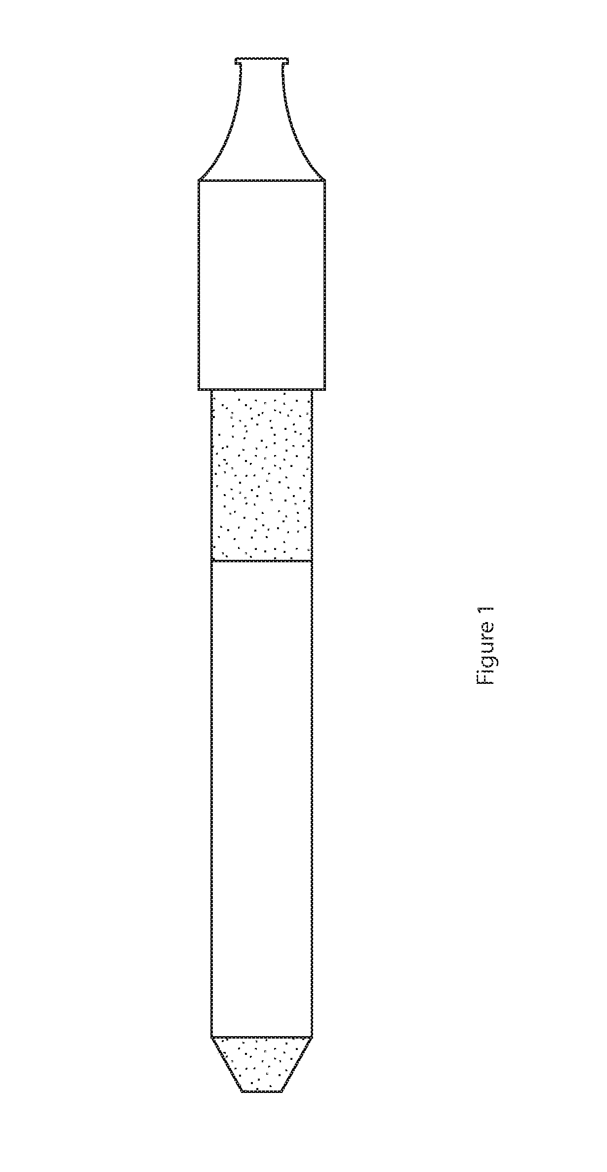
[0005] FIG. 1 is a side view of an electronic cigarette.
[0006] FIG. 2A is a view of the battery assembly.
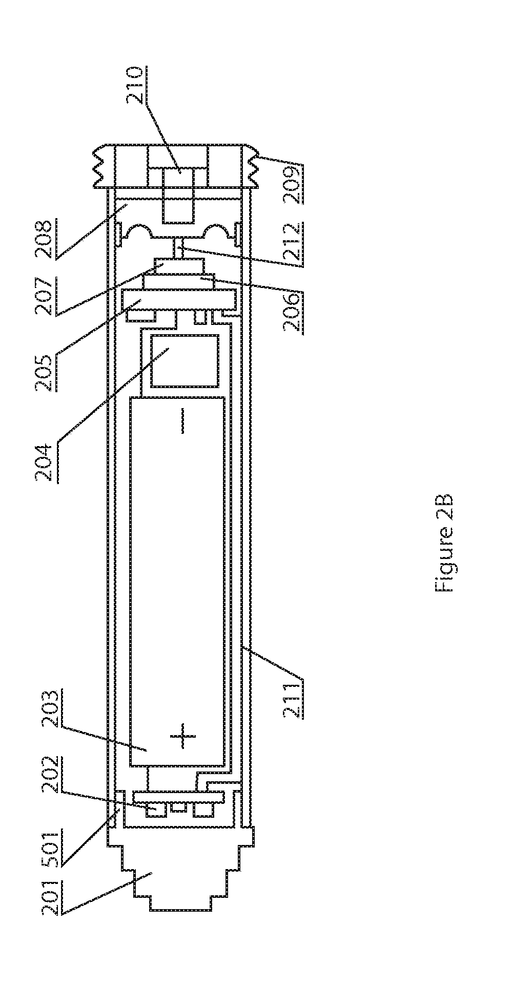
[0007] FIG. 2B is a view of another battery assembly.
[0008] FIG. 3 is the diagram of the atomizer assembly.
[0009] FIG. 4 is the diagram of the cigarette bottle assembly.
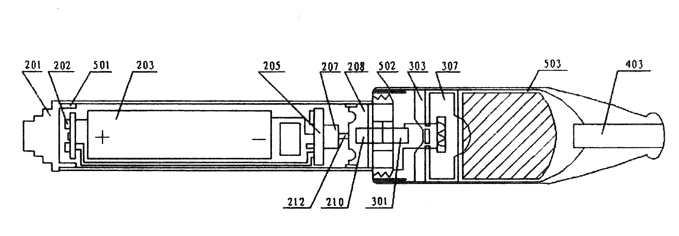
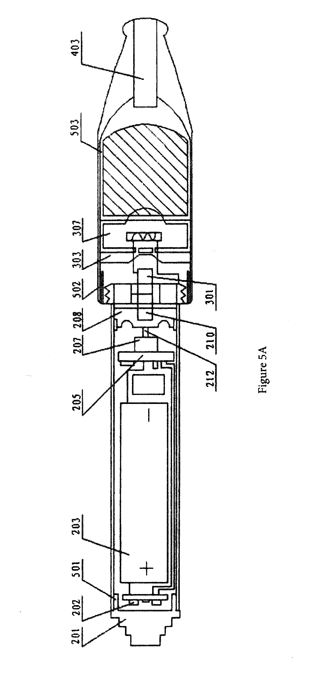
[0010] FIG. 5A is a section view of an electronic cigarette.
[0011] FIG. 5B is a section view of another embodiment.
[0012] FIG. 6 is a diagram of a charger.
[0013] FIG. 7 is the electric circuit diagram.
[0014] FIG. 8 is a side view of an atomizer.
[0015] FIG. 9 is an end view of the atomizer shown in FIG. 8.
[0016] FIG. 10 is a diagram of a spray atomizer.
[0017] FIG. 11 is an end view of the atomizer shown in FIG. 10.
[0018] FIG. 12 is a section view of another embodiment.
DETAILED DESCRIPTION OF THE DRAWINGS
[0019] As shown in FIG. 1, an electronic cigarette has an appearance similar to a cigarette inserted into the cigarette holder. As shown in FIG. 2A, the electronic cigarette includes a battery assembly, an atomizer assembly and a cigarette bottle assembly. An external thread electrode (209) is located in one end of the battery assembly, and an internal thread electrode (302) is located in one end of the atomizer assembly. The battery assembly and atomizer assembly are connected through the screw thread electrode into an electronic cigarette. The cigarette bottle assembly is inserted into the other end of atomizer assembly.
[0020] As shown in FIG. 2A, the battery assembly includes an indicator (202), lithium ion battery (203), MOSFET electric circuit board (205), sensor (207), silica gel corrugated membrane (208), primary screw thread electrode (209), primary negative pressure cavity (210), and primary shell (211). On one end of the primary shell (211) is an external thread electrode (209). On the other end is an indicator (202), where there is an indicator cap (201) on one side having a small hole (501). On the other side, the lithium ion battery (203) and MOSFET (Metallic Oxide Semiconductor Field Effect Tube) electric circuit board (205) are connected successively. The sensor (207) is located on MOSFET electric circuit board (205). Between the primary screw thread electrode (209) and sensor (207) is a silica gel corrugated membrane (208), on which there is the primary negative pressure cavity (210). The sensor (207) is connected with the silica gel corrugated membrane (208) through the switch spring (212).
[0021] The sensor (207) may be switch sensor made of elastic alloy slice, a linear output Hall sensor, a semiconductor force-sensitive chip, a semiconductor matrix thermoelectric bridge chip, capacitance or inductance sensor. The indicators (202) include two red LEDs. The lithium ion battery (203) may be either a rechargeable polymer lithium ion battery or a rechargeable lithium ion battery. The external thread electrode (209) is a gold-coated stainless steel or brass part with a hole drilled in the center. The silica gel corrugated membrane (208) may alternatively be made of fluorinated rubber, butyronitrile rubber, or elastic alloy film.
[0022] As shown in FIG. 3, the atomizer assembly includes the internal thread electrode (302), air-liquid separator (303), atomizer (307) and the secondary shell (306). One end of the secondary shell (306) is inserted into the cigarette bottle assembly for connection, while the other end has an internal thread electrode (302), in which there is the secondary negative pressure cavity (301). The air-liquid separator (303) and the atomizer (307) are connected with the internal thread electrode (302) successively. On the secondary shell (306), there is an air intake hole (502). The air-liquid separator (303) is made of stainless steel or plastic with a hole. The internal thread electrode (302) is a gold-coated stainless steel or brass part with a hole in the center.
[0023] The atomizer (307) may be a capillary impregnation atomizer as in FIGS. 8 and 9, or a spray atomizer as in FIGS. 10 and 11. As shown in FIG. 4, the cigarette bottle assembly includes the cigarette liquid bottle (401), fiber (402) and suction nozzle (403). The fiber (402) containing cigarette liquid is located on one end of the cigarette liquid bottle (401). This end is inserted into the secondary shell (306) and lies against the atomizer (307). The suction nozzle (403) is located on the other end of the cigarette liquid bottle (401). Between the fiber (402) and interior wall of the cigarette liquid bottle (40 I) is an air intake hole (503).
[0024] As shown in FIG. 5A, the standby state has the fully charged battery assembly shown on FIG. 2A fastened onto the atomizer assembly shown on FIG. 3, which is then inserted into the cigarette bottle assembly shown in FIG. 4. When the user slightly sucks the suction nozzle (403), negative pressure forms on the silica gel corrugated membrane (208) through the air intake hole (503) and the primary and secondary negative pressure cavities (210, 301). The silica gel corrugated membrane (208), under the action of suction pressure difference, distorts to drive the switch spring (212) and sensor (207), thus switching MOSFET electric circuit board (205). At this moment, the indicators (202) are lit gradually; the lithium ion battery (203) electrifies the heating body (305) inside the atomizer (307) through MOSFET electric circuit board (205) as well as the internal and external thread electrodes (302, 209).
[0025] The heating body (305) inside the atomizer (307) produces heat. The fiber (402) inside the cigarette liquid bottle (401) contains cigarette liquid, which soaks the micro-porous ceramics (801) inside the atomizer through the fiber (402). The air enters through the air intake hole (502), passes through the run-through hole on the air-liquid separator (303), and helps to form air-liquid mixture in the spray nozzle (304) of the atomizer (307). The air-liquid mixture sprays onto the heating body (305), gets vaporized, and is quickly absorbed into the airflow and condensed into aerosol, which passes through the air intake hole (503) and suction nozzle (403) to form white mist type aerosol.
[0026] When suction stops, the switch spring (212) and sensor (207) are reset; the atomizer (307) stops working; the indicators (202) gradually die down. When the operation times reaches the pre-set value, the atomizer (307) provides a work delay of 5-20 seconds per time, so as to remove the micro-dirt accumulated on the heating body (305).
[0027] Besides the micro-porous ceramics, the liquid supply material of the atomizer (307) may also be foamed ceramics, micro-porous glass, foamed metal, stainless steel fiber felt, terylene fiber, nylon fiber, nitrile fiber, aramid fiber or hard porous plastics. The heating body (305) is made of the micro-porous ceramics on which nickel-chromium alloy wire, iron-chromium alloy wire, platinum wire, or other electro thermal materials are wound. Alternatively, it may be a porous component directly made of electrically conductive ceramics or PTC (Positive Temperature Coefficient) ceramics and associated with a sintered electrode. The surface of the heating body (305) is sintered into high-temperature glaze to fix the zeolite grains, which are made of natural zeolite, artificial non-organic micro-porous ceramics or aluminum oxide grains. The cigarette liquid bottle (401) and suction nozzle (403) in the cigarette bottle assembly are made of non-toxic plastic. The fiber (402) inside of them is made of polypropylene fiber or nylon fiber to absorb cigarette liquid. In the battery assembly, there is a fine hole (501) on the indicator cap (201) for balancing the pressure difference on both sides of the silica gel corrugated membrane (208).
[0028] The cigarette liquid contains 0.1-3.5% nicotine, 0.05-5% tobacco flavor, 0.1-3% organic acid, 0.1-0.5% stabilizer, and propanediol for the remaining.
[0029] The primary and secondary shells (211, 306) are made of stainless steel tube or copper alloy tube with baked-enamel coating of real cigarette color.
[0030] As shown in FIG. 12, the diameter of the battery assembly may be increased in proportion, so that it is consistent with the diameter of the atomizer assembly. Its shell may be decorated with the leaf veins and sub-gloss brown-yellow baked-enamel coating, to create a cigar type device.
[0031] For charging the lithium ion battery (203), the screw thread electrode (601) matches the external thread electrode (209) on the battery assembly, so that it may be used as the charging interface.
[0032] The design in FIG. 2B is difference from the design in FIG. 1A as follows: Microcircuit (206) is added between MOSFET electric circuit board (205) and sensor (207). On the surface of the primary shell (211), there is a screen (204) for display of the power of the lithium ion battery (203) and the sucking times.
[0033] As shown in FIG. 5B, a fully charged battery assembly is attached onto the atomizer assembly, which is then inserted into the cigarette bottle assembly shown on FIG. 4. When the user slightly sucks the suction nozzle (403), negative pressure forms on the silica gel corrugated membrane (208) through the air intake hole (503) and the primary and secondary negative pressure cavities (210, 301). The silica gel corrugated membrane (208), under the action of suction pressure difference, distorts to drive the switch spring (212) and sensor (207), thus activating the Microcircuit (206) and MOSFET electric circuit board (205). At this moment, the indicators (202) are lit gradually; the lithium ion battery (203) electrifies the heating body (305) inside the atomizer (307) through MOSFET electric circuit board (205) as well as the internal and external thread electrodes (302, 209), so that the heating body (305) inside the atomizer (307) produces heat.
[0034] The fiber (402) inside the cigarette liquid bottle (401) contains cigarette liquid, which soaks the micro-porous ceramics (801) inside the atomizer through the fiber (402). The air enters through the air intake hole (502), passes through the run-through hole on the air-liquid separator (303), and helps to form air-liquid mixture in the spray nozzle (304) of the atomizer (307). The air-liquid mixture sprays onto the heating body (305), gets vaporized, and is quickly absorbed into the airflow and condensed into aerosol, which passes through the air intake hole (503) and suction nozzle (403) to form white mist type aerosol.
[0035] As shown in FIG. 7, when the action of suction activates the sensor, Microcircuit (206) scans the sensor (207) in the power-saving mode of pulse, and according to the signal parameters of the sensor (207), restricts the atomizing capacity with the integral function of frequency to single operation time. Also, the microcircuit (206) accomplishes the pulse width modulation and over discharging protection for the constant power output, automatic cleansing for thousands of times per operation, step lighting/dying down control of the indicator, display of the operation times and battery capacity, automatic recovery after sensor malfunction shutdown, etc.
[0036] The unit and its connecting structure may also be loaded with drugs for delivery to the lung.
[0037] Above are just specifications of an example and do not necessarily restrict the scope of protection. Any equivalent modification made on the basis of the design spirit shall fall into the scope of protection.
* * * * *
D00000
D00001
D00002
D00003
D00004
D00005
D00006
D00007
D00008
D00009
D00010
XML
uspto.report is an independent third-party trademark research tool that is not affiliated, endorsed, or sponsored by the United States Patent and Trademark Office (USPTO) or any other governmental organization. The information provided by uspto.report is based on publicly available data at the time of writing and is intended for informational purposes only.
While we strive to provide accurate and up-to-date information, we do not guarantee the accuracy, completeness, reliability, or suitability of the information displayed on this site. The use of this site is at your own risk. Any reliance you place on such information is therefore strictly at your own risk.
All official trademark data, including owner information, should be verified by visiting the official USPTO website at www.uspto.gov. This site is not intended to replace professional legal advice and should not be used as a substitute for consulting with a legal professional who is knowledgeable about trademark law.