Intelligent Charger For An Aerosol Delivery Device
Sur; Rajesh
U.S. patent application number 15/708729 was filed with the patent office on 2019-03-21 for intelligent charger for an aerosol delivery device. The applicant listed for this patent is RAI STRATEGIC HOLDINGS, INC.. Invention is credited to Rajesh Sur.
| Application Number | 20190089180 15/708729 |
| Document ID | / |
| Family ID | 63762571 |
| Filed Date | 2019-03-21 |
| United States Patent Application | 20190089180 |
| Kind Code | A1 |
| Sur; Rajesh | March 21, 2019 |
INTELLIGENT CHARGER FOR AN AEROSOL DELIVERY DEVICE
Abstract
An intelligent charger for an aerosol delivery device includes a housing, first and second connectors connected to the housing, and a power management integrated circuit (PMIC). The first connector is configured to engage a control body of the aerosol delivery device. The second connector is configured to engage a power supply, which is connected with and controllable to provide power to recharge a power source of the control body when the first connector is engaged with the control body and the second connector is engaged with the power supply. The PMIC is configured to obtain measurements of a temperature of the power source, compare the temperature to a predetermined range of temperatures, and control the power provided by the power supply to maintain the temperature within the predetermined range of temperatures during recharge.
| Inventors: | Sur; Rajesh; (Winston-Salem, NC) | ||||||||||
| Applicant: |
|
||||||||||
|---|---|---|---|---|---|---|---|---|---|---|---|
| Family ID: | 63762571 | ||||||||||
| Appl. No.: | 15/708729 | ||||||||||
| Filed: | September 19, 2017 |
| Current U.S. Class: | 1/1 |
| Current CPC Class: | H01M 10/486 20130101; H01M 10/443 20130101; H02J 7/00047 20200101; H02J 7/00041 20200101; H01M 2220/30 20130101; A24F 47/008 20130101; H02J 7/0091 20130101; H02J 7/00 20130101; H01M 2010/4271 20130101; H02J 7/007192 20200101; H02J 7/00034 20200101; H02J 7/0071 20200101 |
| International Class: | H02J 7/00 20060101 H02J007/00; A24F 47/00 20060101 A24F047/00; H01M 10/48 20060101 H01M010/48; H01M 10/44 20060101 H01M010/44 |
Claims
1. An intelligent charger for an aerosol delivery device, the intelligent charger comprising: a housing; a first connector coupled to the housing and configured to engage a control body coupled or coupleable with a cartridge to form the aerosol delivery device, the cartridge being equipped with a heating element and including aerosol precursor composition, and the control body including a power source configured to provide power to the heating element to activate and vaporize components of the aerosol precursor composition; a second connector coupled to the housing and configured to engage a power supply, the power supply being connected with the power source when the first connector is engaged with the control body and the second connector is engaged with the power supply, the power supply being controllable to provide power to recharge the power source; and a power management integrated circuit (PMIC) configured to obtain measurements of a temperature of the power source, compare the temperature to a predetermined range of temperatures, and control the power provided by the power supply to maintain the temperature within the predetermined range of temperatures during recharge.
2. The intelligent charger of claim 1, wherein the PMIC is programmable via an I2C interface to cause the power supply to provide a charging current up to 650 mA.
3. The intelligent charger of claim 1, wherein the PMIC is configured to control the power provided by the power supply based on a predefined charging profile of the power source.
4. The intelligent charger of claim 3, wherein the predefined charging profile is a non-linear charging profile of the power source that is a non-liner power source.
5. The intelligent charger of claim 3, wherein the power source is a battery including an anode and a cathode disposed within an electrolyte, and wherein the PMIC is configured to receive the predefined charging profile from an external computing device configured to create the predefined charging profile from a characterization of at least the electrode.
6. The intelligent charger of claim 1 further comprising a detection device coupled to the PMIC and configured to detect a type of the power supply, the PMIC being configured to set a current limit of the power provided by the power supply based on the type of the power supply detected by the detection device.
7. The intelligent charger of claim 6, wherein the detection device being configured to detect the type of the power supply includes being configured to detect the type of the power from a plurality of different types of power supply including USB 2.0, USB 3.0, USB host port, car charger or wall charger.
8. The intelligent charger of claim 1, wherein the power source includes a terminal or thermistor coupled to the PMIC, and the PMIC being configured to obtain the measurements of the temperature of the power source includes being configured to obtain the measurements of the temperature from the terminal or thermistor.
9. The intelligent charger of claim 1, wherein the PMIC includes a low dropout regulator configured to regulate an output voltage of the power supply from which the power source is rechargeable.
10. The intelligent charger of claim 9, wherein the low dropout regulator is configured as a soft switch to minimize voltage spikes in the output voltage.
Description
TECHNOLOGICAL FIELD
[0001] The present disclosure relates to aerosol delivery devices such as smoking articles, and more particularly to aerosol delivery devices that may utilize electrically generated heat for the production of aerosol (e.g., smoking articles commonly referred to as electronic cigarettes). The smoking articles may be configured to heat an aerosol precursor, which may incorporate materials that may be made or derived from, or otherwise incorporate tobacco, the precursor being capable of forming an inhalable substance for human consumption.
BACKGROUND
[0002] Many devices have been proposed through the years as improvements upon, or alternatives to, smoking products that require combusting tobacco for use. Many of those devices purportedly have been designed to provide the sensations associated with cigarette, cigar, or pipe smoking, but without delivering considerable quantities of incomplete combustion and pyrolysis products that result from the burning of tobacco. To this end, there have been proposed numerous alternative smoking products, flavor generators, and medicinal inhalers that utilize electrical energy to vaporize or heat a volatile material, or attempt to provide the sensations of cigarette, cigar, or pipe smoking without burning tobacco to a significant degree. See, for example, the various alternative smoking articles, aerosol delivery devices and heat generating sources set forth in the background art described in U.S. Pat. No. 8,881,737 to Collett et al., U.S. Pat. App. Pub. No. 2013/0255702 to Griffith Jr. et al., U.S. Pat. App. Pub. No. 2014/0000638 to Sebastian et al., U.S. Pat. App. Pub. No. 2014/0096781 to Sears et al., U.S. Pat. App. Pub. No. 2014/0096782 to Ampolini et al., U.S. Pat. App. Pub. No. 2015/0059780 to Davis et al., and U.S. patent application Ser. No. 15/222,615 to Watson et al., filed Jul. 28, 2016, all of which are incorporated herein by reference. See also, for example, the various implementations of products and heating configurations described in the background sections of U.S. Pat. No. 5,388,594 to Counts et al. and U.S. Pat. No. 8,079,371 to Robinson et al., which are incorporated by reference.
[0003] However, it may be desirable to provide aerosol delivery devices with improved electronics such as may extend usability of the devices.
BRIEF SUMMARY
[0004] The present disclosure relates to aerosol delivery devices, methods of forming such devices, and elements of such devices. The present disclosure includes, without limitation, the following example implementations.
[0005] Some example implementations provide an intelligent charger for an aerosol delivery device, the intelligent charger comprising a housing; a first connector coupled to the housing and configured to engage a control body coupled or coupleable with a cartridge to form the aerosol delivery device, the cartridge being equipped with a heating element and including aerosol precursor composition, and the control body including a power source configured to provide power to the heating element to activate and vaporize components of the aerosol precursor composition; a second connector coupled to the housing and configured to engage a power supply, the power supply being connected with the power source when the first connector is engaged with the control body and the second connector is engaged with the power supply, the power supply being controllable to provide power to recharge the power source; and a power management integrated circuit (PMIC) configured to obtain measurements of a temperature of the power source, compare the temperature to a predetermined range of temperatures, and control the power provided by the power supply to maintain the temperature within the predetermined range of temperatures during recharge.
[0006] In some example implementations of the intelligent charger of any preceding or any subsequent example implementation, or any combination thereof, the PMIC is programmable via an I2C interface to cause the power supply to provide a charging current up to 650 mA.
[0007] In some example implementations of the intelligent charger of any preceding or any subsequent example implementation, or any combination thereof, the PMIC is configured to control the power provided by the power supply based on a predefined charging profile of the power source.
[0008] In some example implementations of the intelligent charger of any preceding or any subsequent example implementation, or any combination thereof, the predefined charging profile is a non-linear charging profile of the power source that is a non-liner power source.
[0009] In some example implementations of the intelligent charger of any preceding or any subsequent example implementation, or any combination thereof, the power source is a battery including an anode and a cathode disposed within an electrolyte, and wherein the PMIC is configured to receive the predefined charging profile from an external computing device configured to create the predefined charging profile from a characterization of at least the electrode.
[0010] In some example implementations of the intelligent charger of any preceding or any subsequent example implementation, or any combination thereof, the intelligent charger further comprises a detection device coupled to the PMIC and configured to detect a type of the power supply, the PMIC being configured to set a current limit of the power provided by the power supply based on the type of the power supply detected by the detection device.
[0011] In some example implementations of the intelligent charger of any preceding or any subsequent example implementation, or any combination thereof, wherein the detection device being configured to detect the type of the power supply includes being configured to detect the type of the power from a plurality of different types of power supply including USB 2.0, USB 3.0, USB host port, car charger or wall charger.
[0012] In some example implementations of the intelligent charger of any preceding or any subsequent example implementation, or any combination thereof, the power source includes a terminal or thermistor coupled to the PMIC, and the PMIC being configured to obtain the measurements of the temperature of the power source includes being configured to obtain the measurements of the temperature from the terminal or thermistor.
[0013] In some example implementations of the intelligent charger of any preceding or any subsequent example implementation, or any combination thereof, the PMIC includes a low dropout regulator configured to regulate an output voltage of the power supply from which the power source is rechargeable.
[0014] In some example implementations of the intelligent charger of any preceding or any subsequent example implementation, or any combination thereof, the low dropout regulator is configured as a soft switch to minimize voltage spikes in the output voltage.
[0015] These and other features, aspects, and advantages of the present disclosure will be apparent from a reading of the following detailed description together with the accompanying drawings, which are briefly described below. The present disclosure includes any combination of two, three, four or more features or elements set forth in this disclosure, regardless of whether such features or elements are expressly combined or otherwise recited in a specific example implementation described herein. This disclosure is intended to be read holistically such that any separable features or elements of the disclosure, in any of its aspects and example implementations, should be viewed as combinable, unless the context of the disclosure clearly dictates otherwise.
[0016] It will therefore be appreciated that this Brief Summary is provided merely for purposes of summarizing some example implementations so as to provide a basic understanding of some aspects of the disclosure. Accordingly, it will be appreciated that the above described example implementations are merely examples and should not be construed to narrow the scope or spirit of the disclosure in any way. Other example implementations, aspects and advantages will become apparent from the following detailed description taken in conjunction with the accompanying drawings which illustrate, by way of example, the principles of some described example implementations.
BRIEF DESCRIPTION OF THE DRAWING(S)
[0017] Having thus described the disclosure in the foregoing general terms, reference will now be made to the accompanying drawings, which are not necessarily drawn to scale, and wherein:
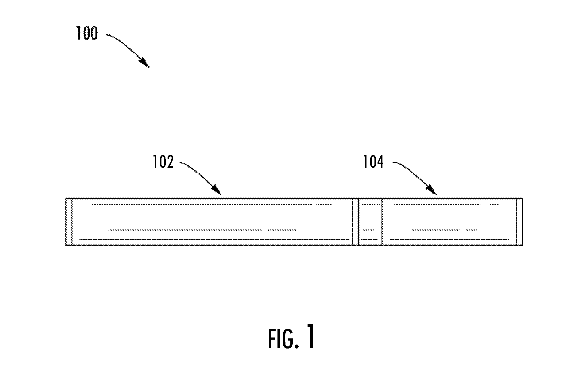
[0018] FIG. 1 illustrates a side view of an aerosol delivery device including a cartridge coupled to a control body, according to an example implementation of the present disclosure;
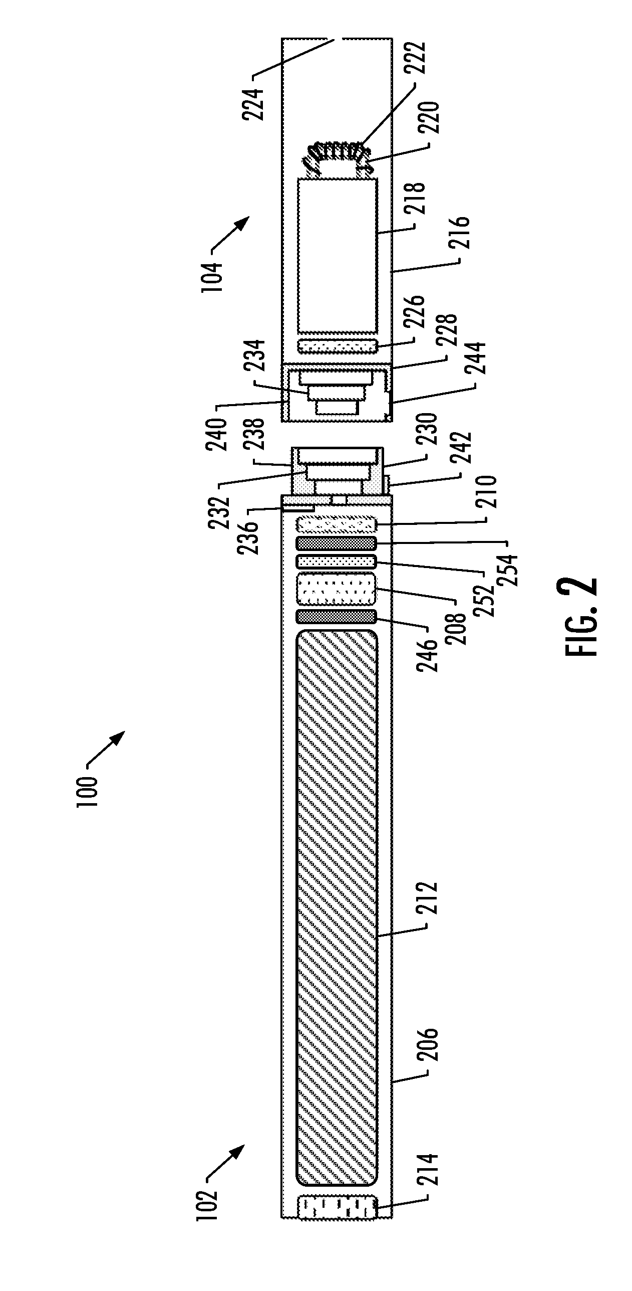
[0019] FIG. 2 is a partially cut-away view of the aerosol delivery device according to various example implementations;
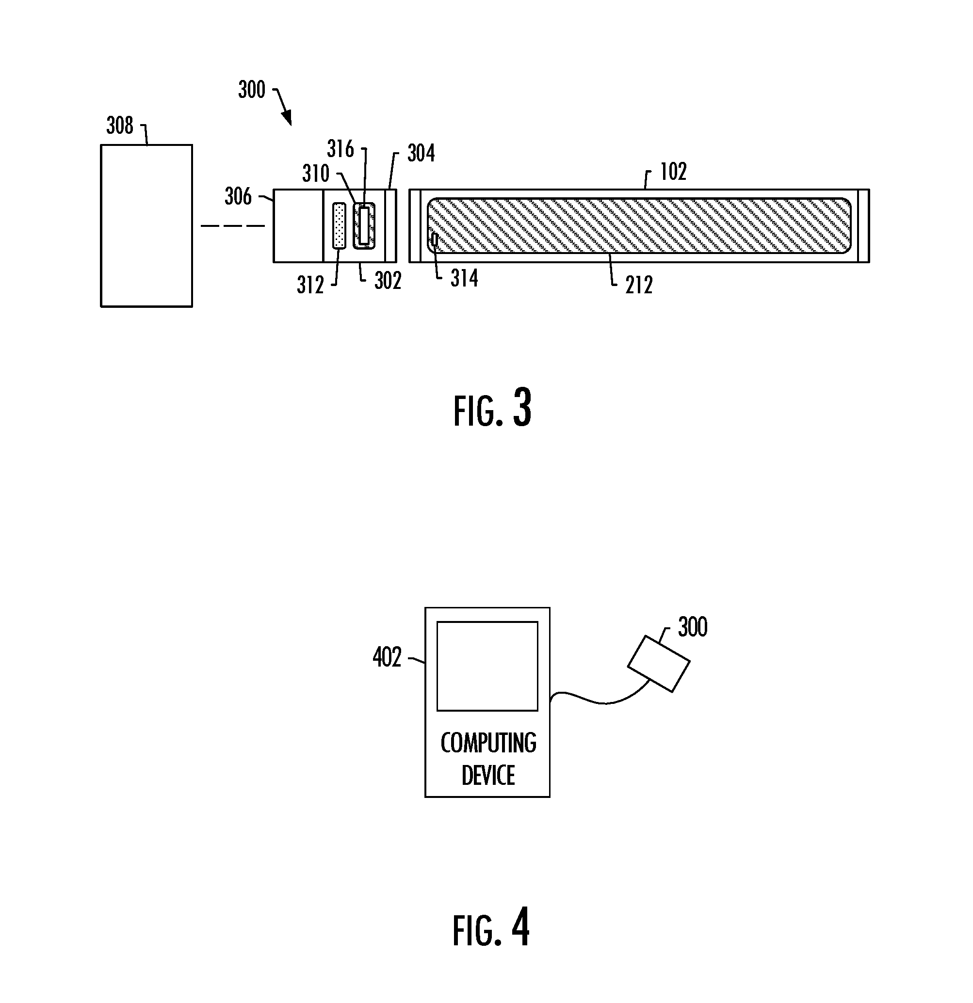
[0020] FIG. 3 is a partially cut-away view of an intelligent charger coupleable to a control body of the aerosol delivery device, according to various example implementations; and
[0021] FIG. 4 illustrates the intelligent charger coupled to an external computing device.
DETAILED DESCRIPTION
[0022] The present disclosure will now be described more fully hereinafter with reference to example implementations thereof. These example implementations are described so that this disclosure will be thorough and complete, and will fully convey the scope of the disclosure to those skilled in the art. Indeed, the disclosure may be embodied in many different forms and should not be construed as limited to the implementations set forth herein; rather, these implementations are provided so that this disclosure will satisfy applicable legal requirements. As used in the specification and the appended claims, the singular forms "a," "an," "the" and the like include plural referents unless the context clearly dictates otherwise.
[0023] As described hereinafter, example implementations of the present disclosure relate to aerosol delivery devices. Aerosol delivery devices according to the present disclosure use electrical energy to heat a material (preferably without combusting the material to any significant degree) to form an inhalable substance; and components of such systems have the form of articles most preferably are sufficiently compact to be considered hand-held devices. That is, use of components of preferred aerosol delivery devices does not result in the production of smoke in the sense that aerosol results principally from by-products of combustion or pyrolysis of tobacco, but rather, use of those preferred systems results in the production of vapors resulting from volatilization or vaporization of certain components incorporated therein. In some example implementations, components of aerosol delivery devices may be characterized as electronic cigarettes, and those electronic cigarettes most preferably incorporate tobacco and/or components derived from tobacco, and hence deliver tobacco derived components in aerosol form.
[0024] Aerosol generating pieces of certain preferred aerosol delivery devices may provide many of the sensations (e.g., inhalation and exhalation rituals, types of tastes or flavors, organoleptic effects, physical feel, use rituals, visual cues such as those provided by visible aerosol, and the like) of smoking a cigarette, cigar or pipe that is employed by lighting and burning tobacco (and hence inhaling tobacco smoke), without any substantial degree of combustion of any component thereof. For example, the user of an aerosol generating piece of the present disclosure can hold and use that piece much like a smoker employs a traditional type of smoking article, draw on one end of that piece for inhalation of aerosol produced by that piece, take or draw puffs at selected intervals of time, and the like.
[0025] While the systems are generally described herein in terms of implementations associated with aerosol delivery devices such as so-called "e-cigarettes," it should be understood that the mechanisms, components, features, and methods may be embodied in many different forms and associated with a variety of articles. For example, the description provided herein may be employed in conjunction with implementations of traditional smoking articles (e.g., cigarettes, cigars, pipes, etc.), heat-not-burn cigarettes, and related packaging for any of the products disclosed herein. Accordingly, it should be understood that the description of the mechanisms, components, features, and methods disclosed herein are discussed in terms of implementations relating to aerosol delivery devices by way of example only, and may be embodied and used in various other products and methods.
[0026] Aerosol delivery devices of the present disclosure also can be characterized as being vapor-producing articles or medicament delivery articles. Thus, such articles or devices can be adapted so as to provide one or more substances (e.g., flavors and/or pharmaceutical active ingredients) in an inhalable form or state. For example, inhalable substances can be substantially in the form of a vapor (i.e., a substance that is in the gas phase at a temperature lower than its critical point). Alternatively, inhalable substances can be in the form of an aerosol (i.e., a suspension of fine solid particles or liquid droplets in a gas). For purposes of simplicity, the term "aerosol" as used herein is meant to include vapors, gases and aerosols of a form or type suitable for human inhalation, whether or not visible, and whether or not of a form that might be considered to be smoke-like.
[0027] In use, aerosol delivery devices of the present disclosure may be subjected to many of the physical actions employed by an individual in using a traditional type of smoking article (e.g., a cigarette, cigar or pipe that is employed by lighting and inhaling tobacco). For example, the user of an aerosol delivery device of the present disclosure can hold that article much like a traditional type of smoking article, draw on one end of that article for inhalation of aerosol produced by that article, take puffs at selected intervals of time, etc.
[0028] Aerosol delivery devices of the present disclosure generally include a number of components provided within an outer body or shell, which may be referred to as a housing. The overall design of the outer body or shell can vary, and the format or configuration of the outer body that can define the overall size and shape of the aerosol delivery device can vary. Typically, an elongated body resembling the shape of a cigarette or cigar can be a formed from a single, unitary housing or the elongated housing can be formed of two or more separable bodies. For example, an aerosol delivery device can comprise an elongated shell or body that can be substantially tubular in shape and, as such, resemble the shape of a conventional cigarette or cigar. In one example, all of the components of the aerosol delivery device are contained within one housing. Alternatively, an aerosol delivery device can comprise two or more housings that are joined and are separable. For example, an aerosol delivery device can possess at one end a control body comprising a housing containing one or more reusable components (e.g., an accumulator such as a rechargeable battery and/or rechargeable supercapacitor, and various electronics for controlling the operation of that article), and at the other end and removably coupleable thereto, an outer body or shell containing a disposable portion (e.g., a disposable flavor-containing cartridge). More specific formats, configurations and arrangements of components within the single housing type of unit or within a multi-piece separable housing type of unit will be evident in light of the further disclosure provided herein. Additionally, various aerosol delivery device designs and component arrangements can be appreciated upon consideration of the commercially available electronic aerosol delivery devices.
[0029] Aerosol delivery devices of the present disclosure most preferably comprise some combination of a power source (i.e., an electrical power source), at least one control component (e.g., means for actuating, controlling, regulating and ceasing power for heat generation, such as by controlling electrical current flow the power source to other components of the article--e.g., a microprocessor, individually or as part of a microcontroller), a heater or heat generation member (e.g., an electrical resistance heating element or other component) or vibrating piezoelectric mesh, which alone or in combination with one or more further elements may be commonly referred to as an "atomizer", an aerosol precursor composition (e.g., commonly a liquid capable of yielding an aerosol upon application of sufficient heat, such as ingredients commonly referred to as "smoke juice," "e-liquid" and "e-juice"), and a mouthend region or tip for allowing draw upon the aerosol delivery device for aerosol inhalation (e.g., a defined airflow path through the article such that aerosol generated can be withdrawn therefrom upon draw).
[0030] Alignment of the components within the aerosol delivery device of the present disclosure can vary. In specific implementations, the aerosol precursor composition can be located near an end of the aerosol delivery device which may be configured to be positioned proximal to the mouth of a user so as to maximize aerosol delivery to the user. Other configurations, however, are not excluded. Generally, the heating element can be positioned sufficiently near the aerosol precursor composition so that heat from the heating element can volatilize the aerosol precursor (as well as one or more flavorants, medicaments, or the like that may likewise be provided for delivery to a user) and form an aerosol for delivery to the user. When the heating element heats the aerosol precursor composition, an aerosol is formed, released, or generated in a physical form suitable for inhalation by a consumer. It should be noted that the foregoing terms are meant to be interchangeable such that reference to release, releasing, releases, or released includes form or generate, forming or generating, forms or generates, and formed or generated. Specifically, an inhalable substance is released in the form of a vapor or aerosol or mixture thereof, wherein such terms are also interchangeably used herein except where otherwise specified.
[0031] As noted above, the aerosol delivery device may incorporate a battery or other electrical power source to provide current flow sufficient to provide various functionalities to the aerosol delivery device, such as powering of a heater, powering of control systems, powering of indicators, and the like. The power source can take on various implementations. Preferably, the power source is able to deliver sufficient power to rapidly heat the heating element to provide for aerosol formation and power the aerosol delivery device through use for a desired duration of time. The power source preferably is sized to fit conveniently within the aerosol delivery device so that the aerosol delivery device can be easily handled. Additionally, a preferred power source is of a sufficiently light weight to not detract from a desirable smoking experience.
[0032] More specific formats, configurations and arrangements of components within the aerosol delivery devices of the present disclosure will be evident in light of the further disclosure provided hereinafter. Additionally, the selection and arrangement of various aerosol delivery device components can be appreciated upon consideration of commercially-available electronic aerosol delivery devices. Further information regarding formats, configurations and arrangements of components within the aerosol delivery devices of the present disclosure, as well as commercially-available electronic aerosol delivery devices, may be found in U.S. patent application Ser. No. 15/291,771 to Sur et al., filed Oct. 12, 2016, which is incorporated herein by reference.
[0033] FIG. 1 illustrates a side view of an aerosol delivery device 100 including a control body 102 and a cartridge 104, according to various example implementations of the present disclosure. In particular, FIG. 1 illustrates the control body and the cartridge coupled to one another. The control body and the cartridge may be detachably aligned in a functioning relationship. Various mechanisms may connect the cartridge to the control body to result in a threaded engagement, a press-fit engagement, an interference fit, a magnetic engagement or the like. The aerosol delivery device may be substantially rod-like, substantially tubular shaped, or substantially cylindrically shaped in some example implementations when the cartridge and the control body are in an assembled configuration. The aerosol delivery device may also be substantially rectangular, rhomboidal or triangular in cross-section, multifaceted shapes, or the like, some of which may lend itself to greater compatibility with a substantially flat or thin-film power source, such as a power source including a flat battery.
[0034] The control body 102 and cartridge 104 may include separate, respective housings or outer bodies, which may be formed of any of a number of different materials.
[0035] The housing may be formed of any suitable, structurally-sound material. In some examples, the housing may be formed of a metal or alloy, such as stainless steel, aluminum or the like. Other suitable materials include various plastics (e.g., polycarbonate), metal-plating over plastic, ceramics and the like.
[0036] In some example implementations, one or both of the control body 102 or the cartridge 104 of the aerosol delivery device 100 may be referred to as being disposable or as being reusable. For example, the control body may have a replaceable battery, rechargeable battery (e.g., rechargeable thin-film solid state battery) or rechargeable supercapacitor, and thus may be combined with any type of recharging technology, including connection to a typical wall outlet, connection to a car charger (i.e., a cigarette lighter receptacle), connection to a computer, such as through a universal serial bus (USB) cable or connector, connection to a photovoltaic cell (sometimes referred to as a solar cell) or solar panel of solar cells, wireless connection to a Radio Frequency (RF), wireless connection to induction-based charging pads, or connection to a RF-to-DC converter. Some examples of suitable recharging technology are described below. Further, in some example implementations, the cartridge may comprise a single-use cartridge, as disclosed in U.S. Pat. No. 8,910,639 to Chang et al., which is incorporated herein by reference.
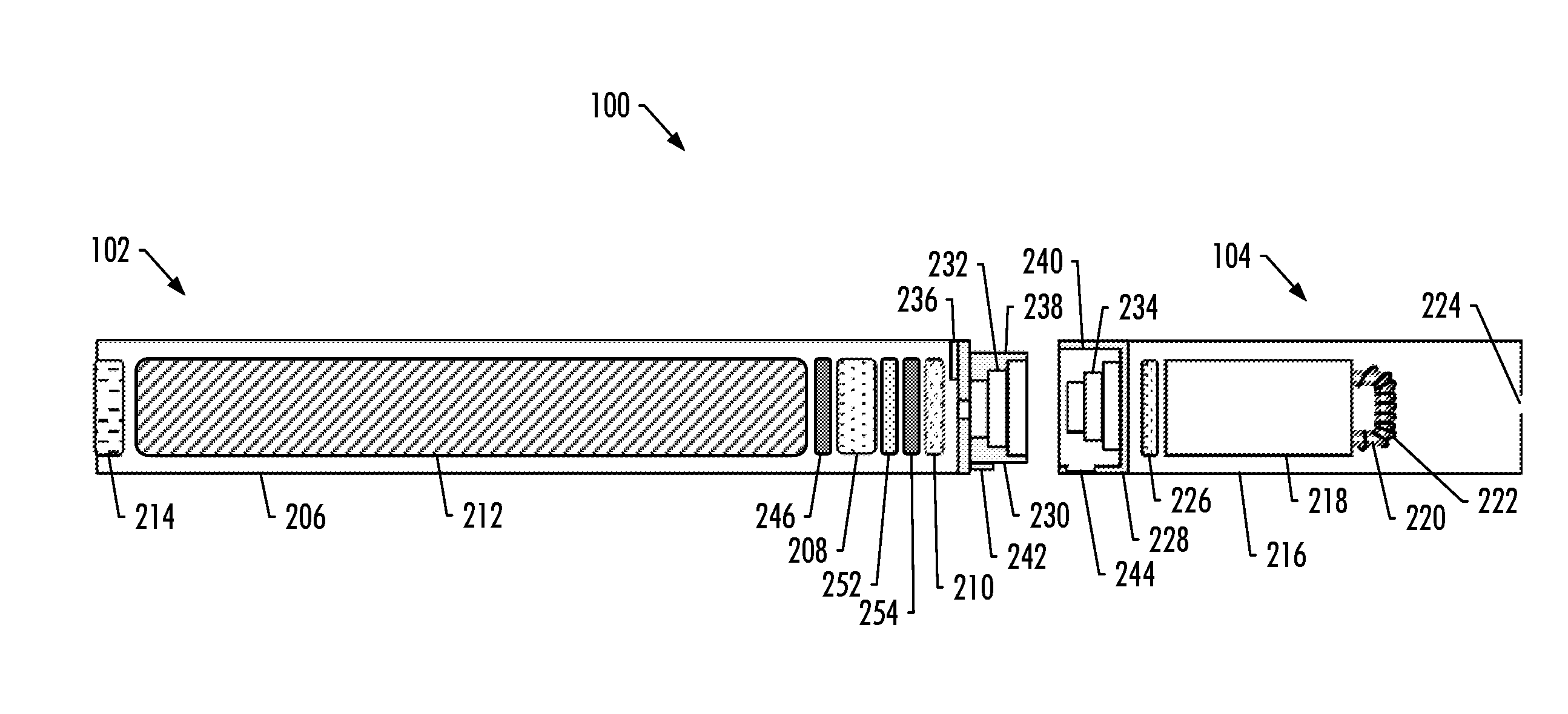
[0037] FIG. 2 more particularly illustrates the aerosol delivery device 100, in accordance with some example implementations. As seen in the cut-away view illustrated therein, again, the aerosol delivery device can comprise a control body 102 and a cartridge 104 each of which include a number of respective components. The components illustrated in FIG. 2 are representative of the components that may be present in a control body and cartridge and are not intended to limit the scope of components that are encompassed by the present disclosure. As shown, for example, the control body can be formed of a control body shell 206 that can include a control component 208 (e.g., a microprocessor, individually or as part of a microcontroller), a flow sensor 210, a power source 212 and one or more light-emitting diodes (LEDs) 214, quantum dot enabled LEDs or the like, and such components can be variably aligned. The power source may include, for example, a battery (single-use or rechargeable), rechargeable supercapacitor, rechargeable solid-state battery (SSB), rechargeable lithium-ion battery (LiB) or the like, or some combination thereof. Some examples of a suitable power source are provided in U.S. patent application Ser. No. 14/918,926 to Sur et al., filed Oct. 21, 2015, which is incorporated herein by reference. Other examples of a suitable power source are provided in U.S. Pat. App. Pub. No. 2014/0283855 to Hawes et al., U.S. Pat. App. Pub. No. 2014/0014125 to Fernando et al., U.S. Pat. App. Pub. No. 2013/0243410 to Nichols et al., U.S. Pat. App. Pub. No. 2010/0313901 to Fernando et al., and U.S. Pat. App. Pub. No. 2009/0230117 to Fernando et al., all of which are incorporated herein by reference.
[0038] The LED 214 may be one example of a suitable visual indicator with which the aerosol delivery device 100 may be equipped. Other indicators such as audio indicators (e.g., speakers), haptic indicators (e.g., vibration motors) or the like can be included in addition to or as an alternative to visual indicators such as the LED, quantum dot enabled LEDs.
[0039] The cartridge 104 can be formed of a cartridge shell 216 enclosing a reservoir 218 configured to retain the aerosol precursor composition, and including a heater 222 (sometimes referred to as a heating element). In various configurations, this structure may be referred to as a tank; and accordingly, the terms "cartridge," "tank" and the like may be used interchangeably to refer to a shell or other housing enclosing a reservoir for aerosol precursor composition, and including a heater.
[0040] As shown, in some examples, the reservoir 218 may be in fluid communication with a liquid transport element 220 adapted to wick or otherwise transport an aerosol precursor composition stored in the reservoir housing to the heater 222. In some examples, a valve may be positioned between the reservoir and heater, and configured to control an amount of aerosol precursor composition passed or delivered from the reservoir to the heater.
[0041] Various examples of materials configured to produce heat when electrical current is applied therethrough may be employed to form the heater 222. The heater in these examples may be a resistive heating element such as a wire coil, micro heater or the like. Example materials from which the heating element may be formed include Kanthal (FeCrAl), Nichrome, stainless steel, Molybdenum disilicide (MoSi.sub.2), molybdenum silicide (MoSi), Molybdenum disilicide doped with Aluminum (Mo(Si,Al).sub.2), graphite and graphite-based materials (e.g., carbon-based foams and yarns) and ceramics (e.g., positive or negative temperature coefficient ceramics). Example implementations of heaters or heating members useful in aerosol delivery devices according to the present disclosure are further described below, and can be incorporated into devices such as those described herein.
[0042] An opening 224 may be present in the cartridge shell 216 (e.g., at the mouthend) to allow for egress of formed aerosol from the cartridge 104.
[0043] The cartridge 104 also may include one or more electronic components 226, which may include an integrated circuit, a memory component (e.g., EEPROM, flash memory), a sensor, or the like. The electronic components may be adapted to communicate with the control component 208 and/or with an external device by wired or wireless means. The electronic components may be positioned anywhere within the cartridge or a base 228 thereof.
[0044] Although the control component 208 and the flow sensor 210 are illustrated separately, it is understood that various electronic components including the control component and the flow sensor may be combined on an electronic printed circuit board
[0045] (PCB) that supports and electrically connects the electronic components. Further, the PCB may be positioned horizontally relative the illustration of FIG. 1 in that the PCB can be lengthwise parallel to the central axis of the control body. In some examples, the air flow sensor may comprise its own PCB or other base element to which it can be attached. In some examples, a flexible PCB may be utilized. A flexible PCB may be configured into a variety of shapes, include substantially tubular shapes. In some examples, a flexible PCB may be combined with, layered onto, or form part or all of a heater substrate.
[0046] The control body 102 and the cartridge 104 may include components adapted to facilitate a fluid engagement therebetween. As illustrated in FIG. 2, the control body can include a coupler 230 having a cavity 232 therein. The base 228 of the cartridge can be adapted to engage the coupler and can include a projection 234 adapted to fit within the cavity. Such engagement can facilitate a stable connection between the control body and the cartridge as well as establish an electrical connection between the power source 212 and control component 208 in the control body and the heater 222 in the cartridge. Further, the control body shell 206 can include an air intake 236, which may be a notch in the shell where it connects to the coupler that allows for passage of ambient air around the coupler and into the shell where it then passes through the cavity 232 of the coupler and into the cartridge through the projection 234.
[0047] A coupler and a base useful according to the present disclosure are described in U.S. Pat. App. Pub. No. 2014/0261495 to Novak et al., which is incorporated herein by reference. For example, the coupler 230 as seen in FIG. 2 may define an outer periphery 238 configured to mate with an inner periphery 240 of the base 228. In one example the inner periphery of the base may define a radius that is substantially equal to, or slightly greater than, a radius of the outer periphery of the coupler. Further, the coupler may define one or more protrusions 242 at the outer periphery configured to engage one or more recesses 244 defined at the inner periphery of the base. However, various other examples of structures, shapes and components may be employed to couple the base to the coupler. In some examples the connection between the base of the cartridge 104 and the coupler of the control body 102 may be substantially permanent, whereas in other examples the connection therebetween may be releasable such that, for example, the control body may be reused with one or more additional cartridges that may be disposable and/or refillable.
[0048] The reservoir 218 illustrated in FIG. 2 can be a container or can be a fibrous reservoir, as presently described. For example, the reservoir can comprise one or more layers of nonwoven fibers substantially formed into the shape of a tube encircling the interior of the cartridge shell 216, in this example. An aerosol precursor composition can be retained in the reservoir. Liquid components, for example, can be sorptively retained by the reservoir. The reservoir can be in fluid connection with the liquid transport element 220. The liquid transport element can transport the aerosol precursor composition stored in the reservoir via capillary action to the heater 222 that is in the form of a metal wire coil in this example. As such, the heater is in a heating arrangement with the liquid transport element.
[0049] In some examples, a microfluidic chip may be embedded in the reservoir 218, and the amount and/or mass of aerosol precursor composition delivered from the reservoir may be controlled by a micro pump, such as one based on microelectromechanical systems (MEMS) technology. The heater 222 may be configured to implement radio-frequency inductive based heating of the aerosol precursor composition without a wick or physical contact with the aerosol precursor composition, such as in a manner described in U.S. patent application Ser. No. 14/934,763 to Davis et al., filed Nov. 6, 2015, which is incorporated by reference. Other example implementations of reservoirs and transport elements useful in aerosol delivery devices according to the present disclosure are further described below, and such reservoirs and/or transport elements can be incorporated into devices such as those described herein. In particular, specific combinations of heating members and transport elements as further described below may be incorporated into devices such as those described herein.
[0050] In use, when a user draws on the aerosol delivery device 100, airflow is detected by the flow sensor 210, and the heater 222 is activated to vaporize components of the aerosol precursor composition. Drawing upon the mouthend of the aerosol delivery device causes ambient air to enter the air intake 236 and pass through the cavity 232 in the coupler 230 and the central opening in the projection 234 of the base 228. In the cartridge 104, the drawn air combines with the formed vapor to form an aerosol. The aerosol is whisked, aspirated or otherwise drawn away from the heater and out the opening 224 in the mouthend of the aerosol delivery device.
[0051] In some examples, the aerosol delivery device 100 may include a number of additional software-controlled functions. For example, the aerosol delivery device may include a power-source protection circuit configured to detect power-source input, loads on the power-source terminals, and charging input. The power-source protection circuit may include short-circuit protection, under-voltage lock out and/or over-voltage charge protection, battery temperature compensation. The aerosol delivery device may also include components for ambient temperature measurement, and its control component 208 may be configured to control at least one functional element to inhibit power-source charging--particularly of any battery--if the ambient temperature is below a certain temperature (e.g., 0.degree. C.) or above a certain temperature (e.g., 45.degree. C.) prior to start of charging or during charging.
[0052] Additionally or alternatively, in some examples, the control component 208 may include a microprocessor with an embedded analog-to-digital converter (ADC) useful for measurement of the temperature of the heater 222. More particularly, for example, the microprocessor may be programmed to cause a fixed current to the heater, and measure the voltage across the heater. The microprocessor may then be configured to calculate the resistance of the heater that varies with temperature from the current and voltage (R=V/I). The resistance may then be used to determine the temperature of the heater from a known relationship between resistance and temperature for the heater material. This relationship may be expressed in a number of different manners, such as by a lookup table.
[0053] Power delivery from the power source 212 may vary over the course of each puff on the device 100 according to a power control mechanism. The device may include a "long puff" safety timer such that in the event that a user or component failure (e.g., flow sensor 210) causes the device to attempt to puff continuously, the control component 208 may control at least one functional element to terminate the puff automatically after some period of time (e.g., four seconds). Further, the time between puffs on the device may be restricted to less than a period of time (e.g., 100 seconds). A watchdog safety timer may automatically reset the aerosol delivery device if its control component or software running on it becomes unstable and does not service the timer within an appropriate time interval (e.g., eight seconds). Further safety protection may be provided in the event of a defective or otherwise failed flow sensor 210, such as by permanently disabling the aerosol delivery device in order to prevent inadvertent heating. A puffing limit switch may deactivate the device in the event of a pressure sensor fail causing the device to continuously activate without stopping after the four second maximum puff time.
[0054] The aerosol delivery device 100 may include a puff tracking algorithm configured for heater lockout once a defined number of puffs has been achieved for an attached cartridge (based on the number of available puffs calculated in light of the e-liquid charge in the cartridge). The aerosol delivery device may include a sleep, standby or low-power mode function whereby power delivery may be automatically cut off after a defined period of non-use. Further safety protection may be provided in that all charge/discharge cycles of the power source 212 may be monitored by the control component 208 over its lifetime. After the power source has attained the equivalent of a predetermined number (e.g., 200) of full discharge and full recharge cycles, it may be declared depleted, and the control component may control at least one functional element to prevent further charging of the power source.
[0055] The various components of an aerosol delivery device according to the present disclosure can be chosen from components described in the art and commercially available. Examples of batteries that can be used according to the disclosure are described in U.S. Pat. No. 9,484,155 to Peckerar et al., which is incorporated herein by reference.
[0056] The aerosol delivery device 100 can incorporate the sensor 210 or another sensor or detector for control of supply of electric power to the heater 222 when aerosol generation is desired (e.g., upon draw during use). As such, for example, there is provided a manner or method of turning off power to the heater when the aerosol delivery device is not be drawn upon during use, and for turning on power to actuate or trigger the generation of heat by the heater during draw. Additional representative types of sensing or detection mechanisms, structure and configuration thereof, components thereof, and general methods of operation thereof, are described in U.S. Pat. No. 5,261,424 to Sprinkel, Jr., U.S. Pat. No. 5,372,148 to McCafferty et al., and PCT Pat. App. Pub. No. WO 2010/003480 to Flick, all of which are incorporated herein by reference.
[0057] The aerosol delivery device 100 most preferably incorporates the control component 208 or another control mechanism for controlling the amount of electric power to the heater 222 during draw. Representative types of electronic components, structure and configuration thereof, features thereof, and general methods of operation thereof, are described in U.S. Pat. No. 4,735,217 to Gerth et al., U.S. Pat. No. 4,947,874 to Brooks et al., U.S. Pat. No. 5,372,148 to McCafferty et al., U.S. Pat. No. 6,040,560 to Fleischhauer et al., U.S. Pat. No. 7,040,314 to Nguyen et al., U.S. Pat. No. 8,205,622 to Pan, U.S. Pat. No. 8,881,737 to Collet et al., U.S. Pat. No. 9,423,152 to Ampolini et al., U.S. Pat. No. 9,439,454 to Fernando et al., and U.S. Pat. App. Pub. No. 2015/0257445 to Henry et al., all of which are incorporated herein by reference.
[0058] Representative types of substrates, reservoirs or other components for supporting the aerosol precursor are described in U.S. Pat. No. 8,528,569 to Newton, U.S. Pat. App. Pub. No. 2014/0261487 to Chapman et al., U.S. Pat. App. Pub. No. 2015/0059780 to Davis et al., and U.S. Pat. App. Pub. No. 2015/0216232 to Bless et al., all of which are incorporated herein by reference. Additionally, various wicking materials, and the configuration and operation of those wicking materials within certain types of electronic cigarettes, are set forth in U.S. Pat. No. 8,910,640 to Sears et al., which is incorporated herein by reference.
[0059] The aerosol precursor composition, also referred to as a vapor precursor composition, may comprise a variety of components including, by way of example, a polyhydric alcohol (e.g., glycerin, propylene glycol or a mixture thereof), nicotine, tobacco, tobacco extract and/or flavorants. Representative types of aerosol precursor components and formulations also are set forth and characterized in U.S. Pat. No. 7,217,320 to Robinson et al., U.S. Pat. No. 9,254,002 to Chong et al., U.S. Pat. No. 8,881,737 to Collett et al., U.S. Pat. Pub. No. 2013/0008457 to Zheng et al., U.S. Pat. Pub. No. 2015/0020823 to Lipowicz et al., and U.S. Pat. Pub. No. 2015/0020830 to Koller, as well as PCT Pat. App. Pub. No. WO 2014/182736 to Bowen et al., and U.S. patent application Ser. No. 15/222,615 to Watson et al., filed Jul. 28, 2016, the disclosures of which are incorporated herein by reference. Other aerosol precursors that may be employed include the aerosol precursors that have been incorporated in the VUSE.RTM. product by R. J. Reynolds Vapor Company, the BLU.TM. product by Imperial Tobacco Group PLC, the MISTIC MENTHOL product by Mistic Ecigs, and the VYPE product by CN Creative Ltd. Also desirable are the so-called "smoke juices" for electronic cigarettes that have been available from Johnson Creek Enterprises LLC.
[0060] Implementations of effervescent materials can be used with the aerosol precursor, and are described, by way of example, in U.S. Pat. App. Pub. No. 2012/0055494 to Hunt et al., which is incorporated herein by reference. Further, the use of effervescent materials is described, for example, in U.S. Pat. No. 4,639,368 to Niazi et al., U.S. Pat. No. 5,178,878 to Wehling et al., U.S. Pat. No. 5,223,264 to Wehling et al., U.S. Pat. No. 6,974,590 to Pather et al., U.S. Pat. No. 7,381,667 to Bergquist et al., U.S. Pat. No. 8,424,541 to Crawford et al., and U.S. Pat. No. 8,627,828 to Strickland et al., as well as U.S. Pat. No. 9,307,787 to Sun et al., U.S. Pat. App. Pub. No. 2010/0018539 to Brinkley et al., and PCT Pat. App. Pub. No. WO 97/06786 to Johnson et al., all of which are incorporated by reference herein. Additional description with respect to implementations of aerosol precursor compositions, including description of tobacco or components derived from tobacco included therein, is provided in U.S. patent application Ser. Nos. 15/216,582 and 15/216,590, each filed Jul. 21, 2016 and each to Davis et al., which are incorporated herein by reference.
[0061] Additional representative types of components that yield visual cues or indicators may be employed in the aerosol delivery device 100, such as visual indicators and related components, audio indicators, haptic indicators and the like. Examples of suitable LED components, and the configurations and uses thereof, are described in U.S. Pat. No. 5,154,192 to Sprinkel et al., U.S. Pat. No. 8,499,766 to Newton, U.S. Pat. No. 8,539,959 to Scatterday, and U.S. Pat. No. 9,451,791 to Sears et al., all of which are incorporated herein by reference.
[0062] Yet other features, controls or components that can be incorporated into aerosol delivery devices of the present disclosure are described in U.S. Pat. No. 5,967,148 to Harris et al., U.S. Pat. No. 5,934,289 to Watkins et al., U.S. Pat. No. 5,954,979 to Counts et al., U.S. Pat. No. 6,040,560 to Fleischhauer et al., U.S. Pat. No. 8,365,742 to Hon, U.S. Pat. No. 8,402,976 to Fernando et al., U.S. Pat. App. Pub. No. 2005/0016550 to Katase, U.S. Pat. No. 8,689,804 to Fernando et al., U.S. Pat. App. Pub. No. 2013/0192623 to Tucker et al., U.S. Pat. No. 9,427,022 to Leven et al., U.S. Pat. App. Pub. No. 2013/0180553 to Kim et al., U.S. Pat. App. Pub. No. 2014/0000638 to Sebastian et al., U.S. Pat. App. Pub. No. 2014/0261495 to Novak et al., and U.S. Pat. No. 9,220,302 to DePiano et al., all of which are incorporated herein by reference.
[0063] As indicated above, the control component 208 includes a number of electronic components, and in some examples may be formed of a PCB. The electronic components may include a microprocessor or processor core, and a memory. In some examples, the control component may include a microcontroller with integrated processor core and memory, and may further include one or more integrated input/output peripherals. In some examples, the control component may be coupled to a communication interface 246 to enable wireless communication with one or more networks, computing devices or other appropriately-enabled devices. Examples of suitable communication interfaces are disclosed in U.S. Pat. App. Pub. No. 2016/0261020 to Marion et al., the content of which is incorporated herein by reference. Another example of a suitable communication interface is the CC3200 single chip wireless microcontroller unit (MCU) from Texas Instruments. And examples of suitable manners according to which the aerosol delivery device may be configured to wirelessly communicate are disclosed in U.S. Pat. App. Pub. No. 2016/0007651 to Ampolini et al., and U.S. Pat. App. Pub. No. 2016/0219933 to Henry, Jr. et al., each of which is incorporated herein by reference.
[0064] FIG. 3 illustrates an intelligent charger 300 for an aerosol delivery device 100 according to various example implementations of the present disclosure. As shown, the intelligent charger includes a housing 302, and first and second connectors 304, 306 coupled to the housing. The first connector is configured to engage the control body 102 coupled or coupleable with a cartridge 104 to form the aerosol delivery device. As described above, the cartridge is equipped with a heater 222 (heating element) and includes aerosol precursor composition, and the control body includes a power source 212 (a number of other components of the control body not being shown in FIG. 2) configured to provide power to the heater to activate and vaporize components of the aerosol precursor composition.
[0065] The second connector 306 is configured to engage a power supply 308 that is connected with the power source 212 when the first connector 304 is engaged with the control body 102 and the second connector is engaged with the power supply. The power supply is controllable to provide power to recharge the power source.
[0066] In accordance with example implementations, the charging voltage of the power source 212 may be adjusted based on its temperature. This adjustment is often referred to as temperature compensation, a charging feature that helps ensure that the power source is neither undercharged nor overcharged regardless of its temperature. Chemical reactions are affected by temperature. Batteries and other similar power sources are electrochemical reactions so they too are affected by temperature. More specifically, for example, cold batteries often require a higher charge voltage in order to push current into the battery plates and electrolyte, and warmer batteries often require a lower charge voltage to eliminate potential damage and unnecessary gassing for a LiB.
[0067] To effect the above temperature adjustment, the intelligent charger 300 of example implementations also includes a power management integrated circuit (PMIC) 310 configured to obtain measurements of a temperature of the power source 212. The PMIC is configured to compare the temperature to a predetermined range of temperatures, and control the power provided by the power supply 308 to maintain the temperature within the predetermined range of temperatures during recharge.
[0068] In some examples, the PMIC 310 is programmable via an I2C interface to cause the power supply 308 to provide a charging current up to 650 mA (e.g., for the power source 212 embodied as a LiB). A power source such as a battery composed of one or more cells may most optimally charge according to a charging profile that relates the charging current to cell voltage and state of charge (SoC). In some examples, the PMIC is configured to control the power provided by the power supply based on a predefined charging profile of the power source, such as predefined constant current constant voltage (CC/CV) charging profile. And in some further examples, the predefined charging profile is a non-linear charging profile of the power source that is a non-liner power source.
[0069] As shown in FIG. 4, in some examples in which the power source 212 is a battery, it includes an anode and a cathode disposed within an electrolyte. In some of these examples, the PMIC 310 is configured to receive the predefined charging profile from an external computing device 402 such as a mobile computer (e.g., portable computer, mobile phones, wearable computer), desktop computer, server computer or the like, which may be coupled to the intelligent charger wirelessly or by wire (e.g., via the I2C interface). In another more application-specific example, the external computing device is a potentiostat such as the model 2450-EC graphical potentiostat from Tektronix. The external computing device may be configured to create the predefined charging profile from a characterization of at least the electrode. The external computing device may create the predefined charging profile in a number of different manners, such as by determination and validation of a SoC profile for a particular charging current, which may then be transmitted to the PMIC.
[0070] Returning to FIG. 3, in some examples, the intelligent charger 300 further includes a detection device 312 coupled to the PMIC 310 and configured to detect a type of the power supply. In some further examples, the detection device is configured to detect the type of the power from a plurality of different types of power supply including USB 2.0, USB 3.0, USB host port, car charger or wall charger. In at least some examples including the detection device, the PMIC is configured to set a current limit of the power provided by the power supply 308 based on the type of the power supply detected by the detection device.
[0071] In some examples, the power source 212 includes a terminal or thermistor 314 coupled to the PMIC 310 (when the first connector 304 is engaged with the control body 102). In these examples, the PMIC is configured to obtain the measurements of the temperature from the terminal or thermistor.
[0072] In some examples, the PMIC 310 includes a low dropout regulator 316 configured to regulate an output voltage of the power supply 308 from which the power source 212 is rechargeable. And in some further examples, the low dropout regulator is configured as a soft switch to minimize voltage spikes in the output voltage.
[0073] One example of a suitable PMIC 310 is the model ADP5350 power management IC from Analog Devices. This PMIC includes a number of additional features that may be beneficial in some example implementations. The PMIC is operable without an external sense resistor, and it includes battery chemistry compensation. The PMIC includes three 150 mA linear regulators that can be used for or in connection with wireless communication (e.g., Bluetooth), organic LED lighting and the like. The PMIC also has five programmable LED outputs that are digitally programmable via an I2C interface.
[0074] The foregoing description of use of the article(s) can be applied to the various example implementations described herein through minor modifications, which can be apparent to the person of skill in the art in light of the further disclosure provided herein. The above description of use, however, is not intended to limit the use of the article but is provided to comply with all necessary requirements of disclosure of the present disclosure. Any of the elements shown in the article(s) illustrated in FIGS. 1-3 or as otherwise described above may be included in an aerosol delivery device according to the present disclosure.
[0075] Many modifications and other implementations of the disclosure set forth herein will come to mind to one skilled in the art to which this disclosure pertains having the benefit of the teachings presented in the foregoing descriptions and the associated drawings. Therefore, it is to be understood that the disclosure is not to be limited to the specific implementations disclosed, and that modifications and other implementations are intended to be included within the scope of the appended claims. Moreover, although the foregoing descriptions and the associated drawings describe example implementations in the context of certain example combinations of elements and/or functions, it should be appreciated that different combinations of elements and/or functions may be provided by alternative implementations without departing from the scope of the appended claims. In this regard, for example, different combinations of elements and/or functions than those explicitly described above are also contemplated as may be set forth in some of the appended claims. Although specific terms are employed herein, they are used in a generic and descriptive sense only and not for purposes of limitation.
* * * * *
D00000
D00001
D00002
D00003
XML
uspto.report is an independent third-party trademark research tool that is not affiliated, endorsed, or sponsored by the United States Patent and Trademark Office (USPTO) or any other governmental organization. The information provided by uspto.report is based on publicly available data at the time of writing and is intended for informational purposes only.
While we strive to provide accurate and up-to-date information, we do not guarantee the accuracy, completeness, reliability, or suitability of the information displayed on this site. The use of this site is at your own risk. Any reliance you place on such information is therefore strictly at your own risk.
All official trademark data, including owner information, should be verified by visiting the official USPTO website at www.uspto.gov. This site is not intended to replace professional legal advice and should not be used as a substitute for consulting with a legal professional who is knowledgeable about trademark law.