Measuring arrangement with a control unit and method for operating such a measuring arrangement
Mueller; Tobias ; et al.
U.S. patent application number 16/016276 was filed with the patent office on 2019-03-21 for measuring arrangement with a control unit and method for operating such a measuring arrangement. The applicant listed for this patent is VEGA GRIESHABER KG, WOLFACH. Invention is credited to Tobias Mueller, Holger Staiger.
| Application Number | 20190086944 16/016276 |
| Document ID | / |
| Family ID | 65526643 |
| Filed Date | 2019-03-21 |

| United States Patent Application | 20190086944 |
| Kind Code | A1 |
| Mueller; Tobias ; et al. | March 21, 2019 |
Measuring arrangement with a control unit and method for operating such a measuring arrangement
Abstract
A measuring arrangement with a control unit, an energy supply unit for a plurality of two-line field devices, which apply a predetermined current upon a measuring loop in which the two-line field devices are respectively arranged, with the two-line field devices being electrically connected to the energy supply unit and communicating digitally with the control unit, with the energy supply unit comprising a voltage controller, which controls an output voltage depending on the number the means of the measuring arrangement for determining a number of two-line field devices operated in the measuring arrangement.
| Inventors: | Mueller; Tobias; (Lauterbach, DE) ; Staiger; Holger; (Hardt, DE) | ||||||||||
| Applicant: |
|
||||||||||
|---|---|---|---|---|---|---|---|---|---|---|---|
| Family ID: | 65526643 | ||||||||||
| Appl. No.: | 16/016276 | ||||||||||
| Filed: | June 22, 2018 |
| Current U.S. Class: | 1/1 |
| Current CPC Class: | G05B 21/02 20130101; G05B 19/0428 20130101; G05F 1/625 20130101; H04B 3/548 20130101; G05B 2223/06 20180801; H04L 67/12 20130101 |
| International Class: | G05F 1/625 20060101 G05F001/625; G05B 21/02 20060101 G05B021/02 |
Foreign Application Data
| Date | Code | Application Number |
|---|---|---|
| Sep 21, 2017 | DE | 10 2017 121 923.4 |
Claims
1. A measuring arrangement comprising a control unit, an energy supply unit for a plurality of two-line field devices, which apply a predetermined current upon a measuring loop in which the two-line field devices are respectively arranged, with the two-line field devices being electrically connected parallel to the energy supply unit and digitally communicate with the control unit, wherein the energy supply unit comprises a voltage controller and the measuring arrangement comprises means for determining a number of two-line field devices operated in the measuring arrangement, and controls the output voltage as a function of the number.
2. The measuring arrangement according to claim 1, wherein the energy supply unit is integrated in the control unit or a modem connected thereto.
3. The measuring arrangement according to claim 1, wherein the energy supply unit is embodied as a separate feeding device.
4. The measuring arrangement according to claim 1, wherein a communication resistor is arranged between the energy supply unit and the two-line field devices, via which a signal modulated on the measuring loop is converted into a voltage that can be detected by the modem and a voltage applied by the modem can be converted into a corresponding current.
5. The measuring arrangement according to claim 1, wherein the output voltage is controlled such that sufficient minimum voltage is applied to each measuring unit to ensure flawless operation.
6. The measuring arrangement according to claim 1, wherein the output voltage is controlled depending on a total current required by the field devices.
7. The measuring arrangement according to claim 1, characterized in that the number of connected field devices can be adjusted.
8. The measuring arrangement according to claim 1, wherein the control unit is battery operated.
9. The measuring arrangement according to claim 1, wherein the control unit and the field devices communicate pursuant to the HART-multidrop protocol with frequency shift keying.
10. A method for operating a measuring arrangement comprising a control unit, an energy supply unit for a plurality of two-line field devices, which apply a predetermined current to a measuring circuit in which the two-line field device are respectively arranged, with the two-line field devices being connected electrically parallel to the energy supply unit and digitally communicate with the control unit, characterized in that an output voltage of the energy supply unit is controlled depending on the number of field devices connected to the energy supply.
11. The method according to claim 10, wherein the measuring arrangement initially adjusts the maximum output voltage, determines a number of field devices located in the measuring arrangement by measuring the current, and then the output voltage is set to an adjusted value.
12. The method according to claim 10, wherein a required output voltage is determined via an inquiry of the necessary minimum voltage of the field devices connected and then the output voltage is adjusted such that at the field devices the highest minimum voltage is applied.
13. The method according to any of the previous claim 10, wherein the number of connected field devices and/or the minimum voltage are cyclically checked and the output voltage is adjusted.
Description
CROSS REFERENCE TO RELATED APPLICATIONS
[0001] This patent application claims priority to German Patent Application 10 2017 121 923.4, filed on Sep. 21, 2017.
STATEMENT REGARDING FEDERALLY SPONSORED RESEARCH OR DEVELOPMENT
[0002] No federal government funds were used in researching or developing this invention.
NAMES OF PARTIES TO A JOINT RESEARCH AGREEMENT
[0003] Not applicable.
SEQUENCE LISTING INCLUDED AND INCORPORATED BY REFERENCE HEREIN
[0004] Not applicable.
BACKGROUND
Field of the Invention
[0005] The invention is a measuring arrangement with a control unit and method for operating such a measuring arrangement.
Background of the Invention
[0006] In technical process automation, field devices are frequently used, which serve to detect and/or influence process variables. Examples for such field devices are fill gauges, limit gauges, and pressure measuring devices with sensors, which detect the respective process variables fill level, limit, or pressure. Frequently such field devices are connected to superordinate units, for example guidance systems or control units. These superordinate units serve for process control, process visualization, and/or process monitoring.
[0007] The energy and/or signal transmission between the field device and the superordinate units occurs frequently according to the 4 mA to 20 mA standard of prior art, in which a 4 mA to 20 mA current circuit and/or a two-wire line is formed between the field device and the superordinate unit. An analog measurement transmission occurs here by adjusting a current loop by the field device. In addition to the analog transmission of signals, the option is given for the measuring devices to transmit digital signals according to the HART-protocol and this way send other information to the superordinate unit or receive such information therefrom. According to the HART-protocol, digital information is superimposed over the analog current signal via frequency shift keying (FSK). Due to the fact that the FSK-modulation is zero mean, the additional signal has no influence upon the analog data transmission.
[0008] The energy supply of the field devices occurs in a direct connection of the superordinate unit and the field device also via the 4 mA to 20 mA current signal, so that both an analog as well as a digital signal path is possible.
[0009] In addition to a direct connection, the so-called multidrop operation allows under the HART-protocol the parallel connection of up to 15 field devices to one current loop. In the multidrop operation the communication occurs exclusively in a digital fashion and the amperage is set to 4 mA per field device. Here, no analog signal transmission occurs.
[0010] Based on the number of field devices connected in the multidrop operation, the energy supply unit of the measuring arrangement must provide amperage adjusted to the number of field devices, which is equivalent to 4 mA times the number of field devices.
[0011] An energy supply of the measuring arrangement occurs typically either via the superordinate unit or through a separately embodied energy supply unit.
[0012] In order to send and receive digital signals, a so-called communication resistor is provided by which the superordinate unit is connected at the input and the output side. The communication resistor is switched serially to the energy supply and converts the modulated current signals into a voltage signal and vice versa.
[0013] Depending on the number of field devices connected, a current, which may lie between 4 mA (one field device) and 60 mA (15 field devices) based on the number of field devices connected, flows through the communication resistor. In a typical capacity of the communication resistor of 250.OMEGA., a voltage drop thus occurs at the communication resistor from 1 V (one field device) to 15 V (15 field devices).
[0014] Due to the fact that it is not known for the superordinate unit how many field devices are arranged or their respective voltage requirements in the measuring arrangement, sufficient voltage must be provided for the permitted maximum voltage of the field devices as well as the maximum number of field devices, and thus sufficient capacity for the maximally dropping voltage must be provided at the communication resistor. If fewer field devices are connected, this voltage is still applied and energy is wasted.
[0015] This condition is considered disadvantageous and it is particularly disadvantageous in battery-operated devices.
[0016] The objective of the present invention is to further develop a measuring arrangement with a control unit, an energy supply unit for a plurality of two-line field devices, applying a predetermined current to a measuring loop in which each of the field devices is arranged, with the two-line field devices being connected electrically parallel to the energy supply unit and digitally communicating with the control unit such that they can be operated in an energy-saving fashion.
[0017] Further, an objective of the present invention is to provide a method for operating such a measuring arrangement.
[0018] This objective is solved in a measuring arrangement having the features of claim 1 as well as a method having the features of claim 10. Advantageous further developments are described in the dependent claims.
BRIEF SUMMARY OF THE INVENTION
[0019] In a preferred embodiment, a measuring arrangement (1) comprising a control unit (3), an energy supply unit (5) for a plurality of two-line field devices (7), which apply a predetermined current (I) upon a measuring loop (9) in which the two-line field devices (7) are respectively arranged, with the two-line field devices (7) being electrically connected parallel to the energy supply unit (5) and digitally communicate with the control unit (3), characterized in that the energy supply unit (5) comprises a voltage controller (6) and the measuring arrangement comprises means for determining a number (n) of two-line field devices (7) operated in the measuring arrangement (1), and controls the output voltage (U.sub.out) as a function of the number (n).
[0020] In another preferred embodiment, the measuring arrangement (1) as described herein, characterized in that the energy supply unit (5) is integrated in the control unit (3) or a modem (11) connected thereto.
[0021] In another preferred embodiment, the measuring arrangement (1) as described herein, characterized in that the energy supply unit (5) is embodied as a separate feeding device.
[0022] In another preferred embodiment, the measuring arrangement (1) as described herein, characterized in that a communication resistor (R.sub.C) is arranged between the energy supply unit (5) and the two-line field devices (7), via which a signal modulated on the measuring loop (9) is converted into a voltage that can be detected by the modem (11) and a voltage applied by the modem (11) can be converted into a corresponding current.
[0023] In another preferred embodiment, the measuring arrangement (1) as described herein, characterized in that the output voltage (U.sub.out) is controlled such that sufficient minimum voltage (U.sub.min) is applied to each measuring unit (71) to ensure flawless operation.
[0024] In another preferred embodiment, the measuring arrangement (1) as described herein, characterized in that the output voltage (U.sub.out) is controlled depending on a total current (I.sub.total) required by the field devices (7).
[0025] In another preferred embodiment, the measuring arrangement (1) as described herein, characterized in that the number (n) of connected field devices (7) can be adjusted.
[0026] In another preferred embodiment, the measuring arrangement (1) as described herein, characterized in that
the control unit (3) is battery operated.
[0027] In another preferred embodiment, the measuring arrangement (1) as described herein, characterized in that the control unit (3) and the field devices (7) communicate pursuant to the HART-multidrop protocol with frequency shift keying (FSK).
[0028] In another preferred embodiment, a method for operating a measuring arrangement (1) comprising a control unit (3), an energy supply unit (5) for a plurality of two-line field devices (7), which apply a predetermined current (I) to a measuring circuit (9) in which the two-line field device (7) are respectively arranged, with the two-line field devices (7) being connected electrically parallel to the energy supply unit (5) and digitally communicate with the control unit, characterized in that an output voltage (U.sub.out) of the energy supply unit (5) is controlled depending on the number (n) of field devices (7) connected to the energy supply (5).
[0029] In another preferred embodiment, the method for operating a measuring arrangement (1) as described herein, characterized in that the measuring arrangement (1) initially adjusts the maximum output voltage (U.sub.out), determines a number (n) of field devices (7) located in the measuring arrangement (1) by measuring the current, and then the output voltage (U.sub.out) is set to an adjusted value.
[0030] In another preferred embodiment, the method for operating a measuring arrangement (1) as described herein, characterized in that a required output voltage (U.sub.out) is determined via an inquiry of the necessary minimum voltage (U.sub.min) of the field devices (7) connected and then the output voltage (U.sub.out) is adjusted such that at the field devices (7) the highest minimum voltage (U.sub.min) is applied.
[0031] In another preferred embodiment, the method for operating a measuring arrangement (1) as described herein, characterized in that the number (n) of connected field devices (7) and/or the minimum voltage (U.sub.min) are cyclically checked and the output voltage (U.sub.out) is adjusted.
BRIEF DESCRIPTION OF THE DRAWINGS
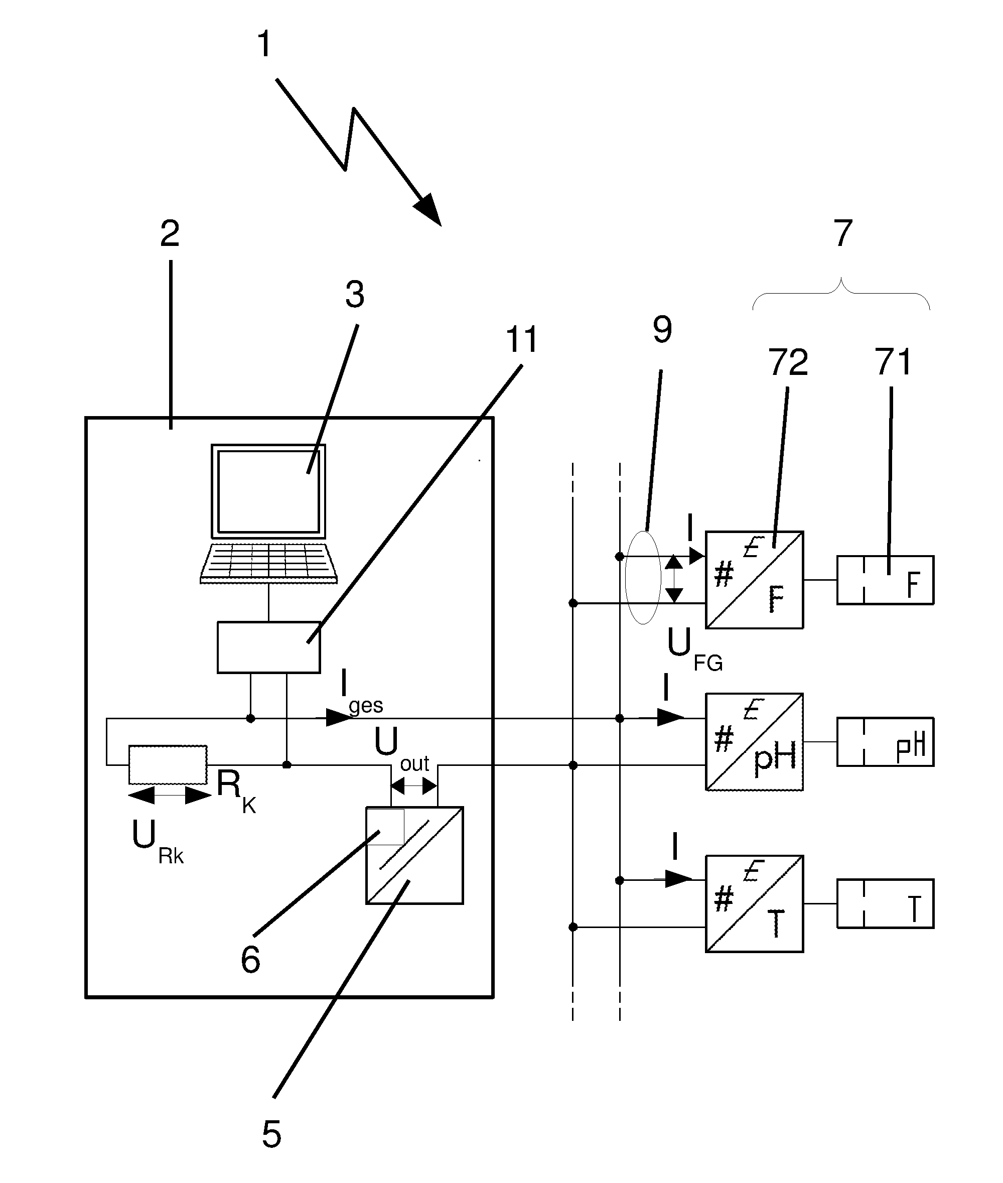
[0032] FIG. 1 is a line drawing evidencing a block diagram with a measuring arrangement according to the present invention,
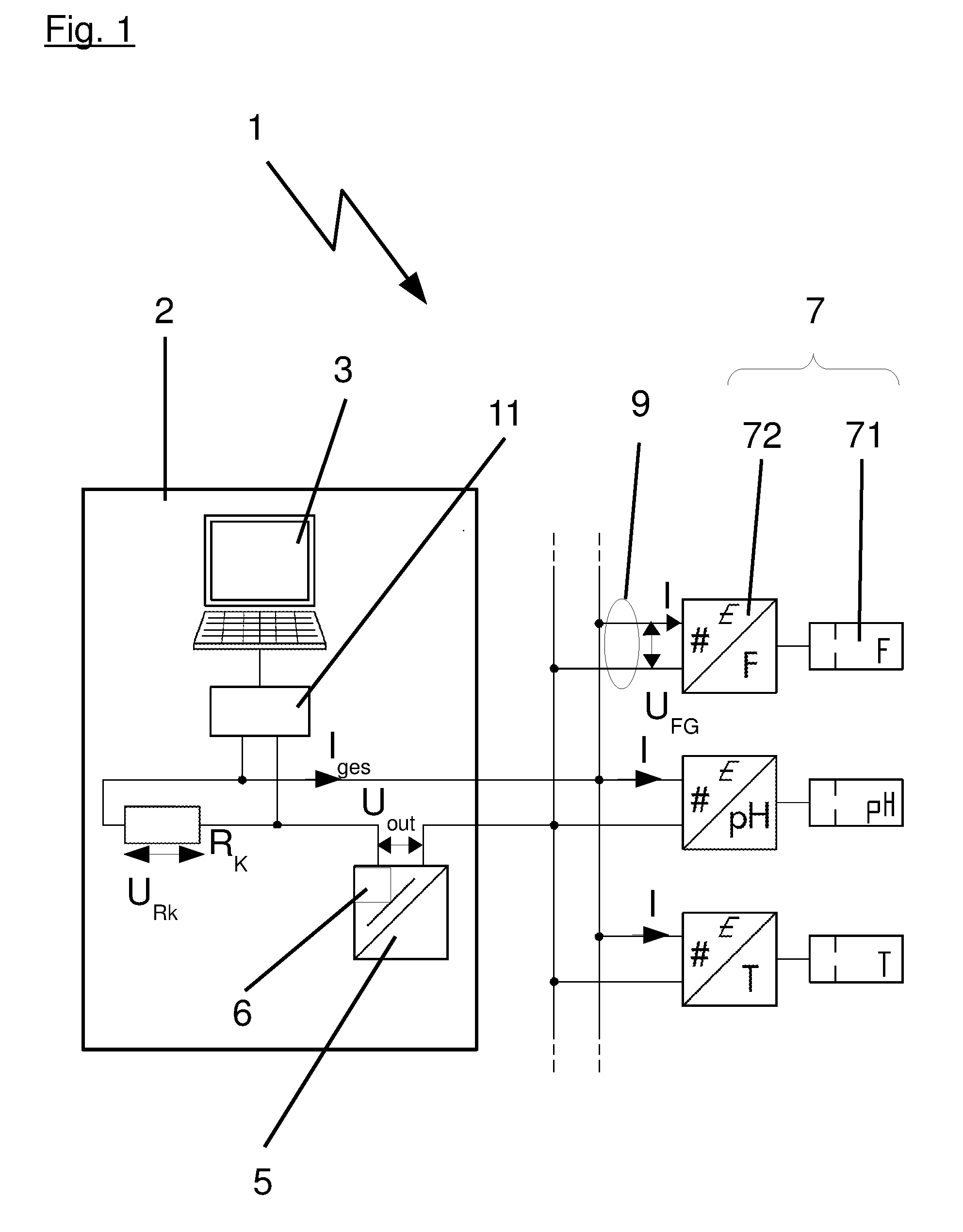
[0033] FIG. 2 is a line drawing evidencing a simplified block diagram of a measuring arrangement with 15 field devices connected.
[0034] FIG. 3 is a line drawing evidencing the block diagram according to FIG. 2 with one field device connected according to prior art.
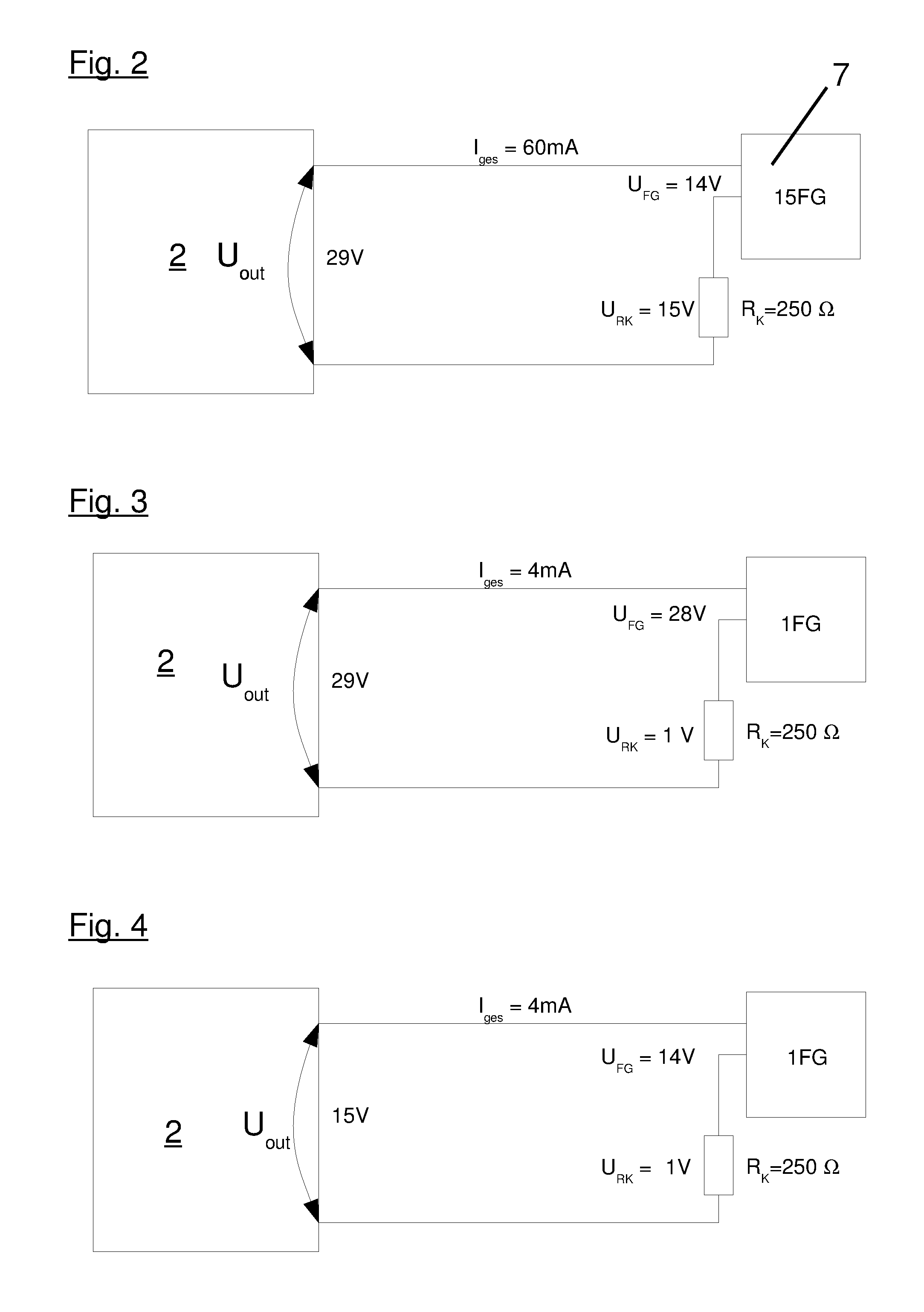
[0035] FIG. 4 is a line drawing evidencing the block diagram according to FIG. 2 with one field device connected according to the present invention.
[0036] FIG. 5a, 5b are line drawings evidencing two variants of the method according to the present application with a current measurement.
[0037] FIG. 6 is a line drawing evidencing a third variant of the method according to the present application.
DETAILED DESCRIPTION OF THE INVENTION
[0038] The invention is a measuring arrangement comprising at least a control unit, an energy supply unit for a plurality of two-line field devices, applying a predetermined current upon a measuring loop in which the field devices are respectively arranged, with the two-line field devices being electrically connected parallel to the energy supply unit and communicating digitally with the control device, is characterized in that the measuring arrangement comprises means for determining a number of field devices operated in the measuring arrangement, particularly field devices connected to the energy supply unit, with the energy supply unit showing a voltage controller regulating the output voltage depending on the number.
[0039] Such a measuring arrangement allows control the output voltage of the energy supply unit based on the number of field devices connected and thus depending on the current required by these field devices. In a particularly simple embodiment, the current flowing through the communication resistor and/or a voltage dropping at the resistor are measured. When the resistivity of the communication system is known, conclusions can be drawn about the current and thus the number of field devices present. It is also possible to exclusively use the voltage drop at the communication resistor for regulating the output voltage.
[0040] Particularly beneficial is the use of the present measuring arrangement in field devices which are connected to the control unit in the so-called HART-multidrop mode. In this type of communication, each of the field devices applies a device current of 4 mA upon the measuring loop utilized thereby such that, depending on the number of connected field devices, additional resistors, particularly a communication resistor of the measuring device can be flown through by a multiple of the device current, particularly outside the parallel circuitry of the field devices. Accordingly, more or less voltage drops at these resistors.
[0041] When the output voltage of the energy supply unit is controlled as a function of the number of field devices connected, in the event that less voltage drops in the additional resistors due to a lower applied current, energy can thus be saved.
[0042] Thus the energy supply unit can beneficially be integrated in the control unit or a modem connected thereto, or be embodied as a separate feeding unit.
[0043] When integrated in the control unit or the modem a particularly simple design is yielded, because fewer separate devices need to be installed.
[0044] If the energy supply unit is embodied as a separate feeding device, the design of the control unit and/or the modem can be simplified accordingly. The devices therefore become more economical.
[0045] In order to allow communication between the field devices and the control unit, it is necessary to convert a current signal modulated upon the two-wire line into voltage. For this purpose a communication resistor is arranged between the energy supply unit and the field devices. It converts the signal modulated upon the measuring loop into a voltage that can be detected by the modem, and a voltage applied by the modem into a corresponding current. The resistivity of the communication system and the amperage flowing through it must be considered for the control of the output voltage.
[0046] In order to ensure flawless operation of the field devices, the required minimum voltage must be provided to them, which is, however, dependent on the respective field device. In many measuring arrangements the minimum voltage amounts to 14 V, however it may also amount to 9.6 V or a different voltage, depending on the field devices used. It is therefore constantly attempted to develop devices which use as little voltage as possible. Based on the information regarding the respectively given measuring arrangement, the output voltage can be controlled in a manner such that voltage is applied to each sensor which is sufficient for flawless operation.
[0047] As already mentioned, the field devices are typically operated in the suggested measuring arrangement with a current of 4 mA. It may vary, however, depending on the respective application. Advantageously, the output voltage is therefore controlled depending on the current required by the field devices.
[0048] In an alternative embodiment, the output voltage can be controlled depending on an adjustable number of connected field devices. Thus a current measurement can be waived and the field device can be embodied in a respectively simpler fashion.
[0049] The present invention is particularly suited for battery operated measuring arrangements, since in these energy savings by way of voltage control provide particularly important advantages. Field devices such as level meters for rivers or overflow basins, or snow level meters for the alpine region frequently exhibit no wired energy supply units, and are thus battery operated. When energy savings can be achieved for such devices, their lifespan is lengthened, which allows less frequent battery changes and perhaps longer maintenance intervals. The operation of the devices is therefore possible in a much more cost-effective fashion.
[0050] The present invention is particularly suited for measuring arrangements in which the control unit and the field devices communicate according to the HART multidrop protocol via frequency shift keying (FSK). The HART multidrop protocol provides that the field devices are respectively arranged in a 4 mA current loop and connected parallel to the control unit. An energy supply unit may be arranged inside the control unit itself in a HART-modem coupled to the control unit, or in a feeding unit.
[0051] A method according to the invention for operating a measuring arrangement with a control unit, an energy supply unit for a plurality of two-line field devices, which apply a predetermined current to a measuring loop in which the field devices are respectively arranged, with the two-line field devices being connected electrically parallel to the energy supply unit and digitally communicating with the control device, is characterized in that an output voltage of the energy supply unit is controlled depending on the number of field devices connected to the energy supply unit.
[0052] The method for operating the measuring arrangement can thus essentially be implemented in the control unit or the voltage supply such that in a first embodiment no changes are required in the field devices.
[0053] The method may provide that the energy supply unit initially adjusts the maximum voltage, determines a number of field devices located in the measuring device by way of current measurement, and then the output voltage is set for an adjusted value.
[0054] In this process it is initially ensured that sufficient supply voltage is available for all field devices connected. Due to the fact that each of the field devices in the suggested operating mode applies a predetermined current, particularly 4 mA, into its respective measuring loop, the total amperage 4 mA flowing from the energy supply unit is multiplied with the number of field devices connected. With the value of the communication resistor as well as potentially present additional resistors, using the total amperage, here the voltage dropping at the communication resistor can be calculated as well or alternatively measured such that the voltage applied to the field devices can be calculated.
U.sub.FD=U.sub.out-U.sub.RC=U.sub.out-I.sub.total.times.R.sub.C
[0055] In the present formula
[0056] U.sub.FD represents the voltage applied to the field devices
[0057] U.sub.out represents the output voltage of the energy supply unit
[0058] I.sub.total represents the total amperage applied by the field devices
[0059] R.sub.C represents the communication resistor
[0060] If, based on the current measurement, the overall current is known, and from the knowledge of the measuring arrangement the minimum voltage required for operating the field devices as well as the value of the communication resistor are known, the necessary output voltage can be calculated as follows:
U.sub.out=U.sub.min+U.sub.RC=U.sub.min+I.sub.total.times.R.sub.C
[0061] In the present formula
[0062] U.sub.out represents the output voltage of the energy supply unit
[0063] I.sub.totalrepresents the total current applied by the field de vices
[0064] R.sub.C represents the communication resistor
[0065] U.sub.min represents the maximum minimum voltage required for flaw-less operation of the field devices.
[0066] In a further development of the method, the required output voltage can be determined through an inquiry of the required minimum voltage of the connected field devices, and then the output voltage can be adjusted such that the maximum determined minimum voltage is applied to the field devices.
[0067] The HART-protocol allows the manufacturers to render manufacturer-specific inquiries with manufacturer-specific commands. Thus it can be provided that in the method the minimum voltage required for the safe operation of a field device is inquired and then adjusted to the output voltage such that the maximum determined minimum voltage is applied at the field devices.
[0068] Further, the number of connected field devices and/or the minimum voltage of the field devices can be cyclically checked and the output voltage can be adjusted to the number of field devices connected. Thus it is also detected if in the meantime field devices have been connected without any notification to the superordinate unit and/or the energy supply unit.
Detailed Description of the Figures
[0069] FIG. 1 shows a block diagram of a measuring arrangement 1 in which a plurality of two-line field devices 7, hereinafter simply called field devices, are connected via the two-wire line electrically parallel to a superordinate unit 2. The superordinate unit 2 comprises in the present exemplary embodiment a control unit 3, a modem 11 connected to the control unit 3, which is connected to the two-wire line, and an energy supply unit 5 with a voltage controller 6.
[0070] The modem 11 is suitably designed in the exemplary embodiment for frequency shift keying (FSK) and connected via a communication resistor R.sub.C to the two-wire line. The communication resistor R.sub.C converts any digital signal modulated by the field devices 7 upon the two-wire line into a voltage that can be tapped by the modem 11. Inversely, a voltage applied by the modem 11 to the communication resistor R.sub.C is converted into a corresponding current signal and rendered available on the two-wire line.
[0071] The present measuring arrangement is a measuring arrangement for the HART multidrop operation in which the field devices 7 exchange data with the superordinate unit 2 in accordance with the HART-protocol and a constant current I of 4 mA is applied by each field device 7 upon its respective (sic). Due to the fact that, based on the HART multidrop operation, up to 15 field devices 7 can be connected parallel to the two-wire line, the total current I.sub.total rendered available by the energy supply unit may vary between 4 mA and 60 mA, depending on the number of field devices 7 connected.
[0072] The voltage supply unit 5 comprises in the present exemplary embodiment a voltage controller 6, which is suitably embodied to adjust an output voltage U.sub.out rendered available by the voltage supply 5 to a number n of field devices 7 connected to the two-wire line.
[0073] In the present exemplary embodiment, the field devices 7 respectively comprise a measuring device 71 as well as a HART-interface 72 and apply a constant current I of 4 mA upon the respective measuring loop 9 it is connected to. Depending on the respective measuring device 71 it requires a minimum voltage U.sub.min in order to ensure the correct operation of the field device 7. The voltage controller 6 can adjust the output voltage U.sub.out of the energy supply unit 5 such that a field device voltage U.sub.FD applied at the field devices 7 is equivalent to the minimum voltage U.sub.min required for the field devices 7, and the voltage drop at the communication resistor R.sub.C, can be minimized based on the sum of the currents I applied by the field devices 7, thus based on the total current I.sub.total.
[0074] In order to ensure reliable operation of all field devices 7, the respectively highest minimum voltage U.sub.min shall be used for determining the output voltage U.sub.out.
[0075] This is explained in greater detail in the following figures.
[0076] FIG. 2 shows a simplified block diagram of the arrangement of FIG. 1, with a total of 15 field devices 7 being connected parallel to the superordinate unit 2, in the present case only shown in a single block. For the purpose of illustrating the present problem, the communication resistor R.sub.C is shown in the present exemplary embodiment not within the superordinate unit 2, but separately between the field devices 7 and the superordinate unit 2.
[0077] A minimum voltage U.sub.min for the correct operation of the field devices 7 is given in the present exemplary embodiment at 14 Volts, so that a voltage U.sub.FD applied at the field devices 7 is given with 14 Volts. Due to the fact that the 15 field devices according to the above description apply respectively 4 mA current to their respective measuring loop 9, the total current I.sub.total, which in the present exemplary embodiment must be provided by the energy supply unit 5, must be 15.times.4 mA, thus 60 mA. Based on the total current I.sub.total of 60 mA, which, as shown in the present case, also flows through the communication resistance R.sub.C, here showing a capacity of 250.OMEGA., shows at the communication resistor R.sub.C a voltage drop of U.sub.RC with a value of
U.sub.RC=I.sub.total.times.R.sub.C 60 mA.times.250.OMEGA.=15 V,
so that the energy supply unit 5 must provide an output voltage U.sub.out with a value of
U.sub.out=U.sub.FD+U.sub.RC=14 V+15 V=29 V.
[0078] This means that for operating 15 field devices the energy supply unit 5 must provide an output voltage U.sub.out measuring 29 V.
[0079] FIG. 3 is shown, similar to the arrangement 1 according to FIG. 2, with only one field device 7 being connected. Due to the fact that the superordinate unit 2 and/or the energy supply unit 5 have no information about the number of field devices 7 operated in the measuring arrangement 1, said arrangement in turn provides the output voltage U.sub.out measuring 29 V. The single field device 7 applies, as shown above, a current I measuring 4 mA upon the measuring loop 9, which in the given exemplary embodiment comprises only one field device 7, is equivalent to the total current I.sub.total. According to the applied total current I.sub.total of 4 mA, at the communication resistor R.sub.C measuring 250.OMEGA. a voltage U.sub.RC of 1 V drops. Accordingly, the voltage applied at a field device 7 amounts to
U.sub.FD=U.sub.out-U.sub.RC=29 V-1 V=28 V.
[0080] The voltage U.sub.FD applied at the field device 7, measuring 28 V, is therefore twice as high as it needs to be.
[0081] FIG. 4 shows the measuring arrangement 1 of FIG. 3 in an embodiment according to the present application. According to the present application, the energy supply unit 5 is equipped with a voltage controller 6, and shows means suitable to detect a number n of connected field devices 7, and to adjust the output voltage U.sub.out of the energy supply unit 5 to the number n of connected field devices 7. In the present exemplary embodiment, by measuring the total current I.sub.total, it is detected that only one field device 7 is operated in the measuring arrangement 1 and, based on the total current I.sub.total measuring 4 mA at the communication resistor RC, only a voltage U.sub.RC of 1 V drops. The knowledge that a flawless operation of the field device 7 requires a minimum voltage U min of 14 V allows the adjustment of the output voltage U.sub.out to a value of
U.sub.out=U.sub.FD+U.sub.RC=U.sub.min+U.sub.RC=14 V+1 V=15 V.
[0082] This way, considerable energy savings can be achieved and the output voltage U.sub.out provided by the energy supply unit 5 can be considerably reduced.
[0083] Alternatively, the voltage dropping at the communication resistor R.sub.C can be measured and used for the above calculation.
[0084] FIG. 5 shows the process of a potential method for operating a measuring arrangement 1 according to FIG. 4. In a first step, the measuring arrangement 1 is operated and subsequently the output voltage U.sub.out of the energy supply unit 5 is set to a maximum voltage U.sub.max, which is maximally necessary for the measuring arrangement 1. In order to ensure the flawless operation of all field devices, even in case of a maximum quantity of field devices 7.
[0085] In the event that the voltage required by the field devices 7 for flawless operation, the minimum voltage U.sub.min is, for example, 14 V and the communication resistor R.sub.C is provided with a capacity of 250.OMEGA., the maximum necessary voltage U.sub.max represents the voltage required for the maximum potential current loop, i.e. a total current I.sub.total for 15 connected field devices 7. In the above-shown examples this would therefore be
U.sub.max=U.sub.min+R.sub.C.times.I.sub.total=14 V+250.OMEGA..times.15 V=29 V.
[0086] In case of different values of the minimum voltage U.sub.min or the capacity of the communication resistor R.sub.C, the maximum voltage U.sub.max changes accordingly.
[0087] When all field devices 7 are in operation and apply the specified current of 4 mA per field device to the respective measuring loop 9, the total current I.sub.total is determined, such that the voltage U.sub.RC dropping at the communication resistor R.sub.C can be calculated. The output voltage U.sub.out is then set to the total of the highest minimally required voltage for flawless operation of the field devices U.sub.min and the voltage U.sub.RC dropping at the communication resistor R.sub.C.
[0088] The variant of the method of FIG. 5a, shown in FIG. 5b, determines in addition to the total current I.sub.total also the minimum voltage U.sub.min for the flawless operation of the field devices 7 by an inquiry of the field devices 7. Here, the HART-protocol allows manufacturer-specific inquiries, by which, for example, a minimum voltage U.sub.min can be inquired about the operation of the respective field device 7. Once the minimum voltages U.sub.min of all field devices 7 have been inquired, the output voltage U.sub.out of the energy supply unit 5 is set to the total of the highest minimum voltage U.sub.min and the voltage U.sub.RC dropping at the communication resistor R.sub.C. Further, another step is implemented that cyclically checks the number n of the field devices 7 operated in the measuring arrangement 1, with this in the present exemplary embodiment being implemented by waiting for a predetermined number of, for example 10, seconds and subsequently a renewed process of determining the total current I.sub.total, determining the minimum voltage U.sub.min, as well as adjusting the output voltage U.sub.out. The time elapsed until processing another cycle may range from a few seconds to several days.
[0089] Such a cyclical post-regulation may also occur in all of the exemplary embodiments shown here.
[0090] FIG. 6 shows a third variant of the method for operating a measuring arrangement 1 according to the present application.
[0091] After the start of operation, in this case the output voltage U.sub.out is also set to the maximum output voltage U.sub.max. Subsequently, the number n of the field devices 7, operated in the measuring arrangement 1, is, for example, determined by inquiring the issued device addresses in the measuring arrangement 1. Further, by a manufacturer-specific inquiry explained in reference to FIG. 5b, the minimum voltage U.sub.min for the flawless operation of the field devices 7 is learned, and the value of the output voltage U.sub.out is subsequently adjusted to the value of the highest minimum voltage U.sub.min plus the voltage U.sub.RC at the communication resistor R.sub.C. The voltage U.sub.RC dropping at the communication resistor R.sub.C is calculated in the present exemplary embodiment from the number n of field devices 7 operated in the measuring arrangement 1 multiplied with the current of 4 mA applied by the field devices 7, in turn multiplied with the capacity of the communication resistor R.sub.C.
U.sub.RC=R.sub.C.times.I.sub.total=R.sub.C.times.n.times.4 mA
[0092] There is a plurality of potential embodiments for the measuring arrangement 1 according to the present invention as well as for the present method, without this deviating from the fundamental concept of the present invention, namely the reduction of the output voltage U.sub.out of the energy supply unit 3 of the measuring arrangement 1 depending on the number n of field devices 7 operated in the measuring arrangement 1.
[0093] When adjusting the voltage, the voltage dropping at the communication resistor must always be considered. The output voltage must thus be adjusted such that it is equivalent to the minimum voltage required for the field devices plus the voltage dropping at the communication resistor.
U.sub.out=U.sub.min+U.sub.RC=U.sub.min+I.times.R.sub.C
[0094] Resistivity is not considered in the above description, for reasons of simplification; however, it may also be relevant depending on the length of the wire. Resistivity is proportional to the length of the supply line so that the voltage dropping would have to be considered as follows:
U.sub.L=I.times.R.sub.L=I.times.R.sub.L.times.1.
LIST OF REFERENCE NUMBERS
[0095] 1 Measuring arrangement [0096] 2 Superordinate unit [0097] 3 Control unit [0098] 5 Energy supply unit [0099] 6 Voltage controller [0100] 7 Two-line field devices/field devices [0101] 9 Measuring loop [0102] 11 Modem [0103] 71 Measuring device [0104] 72 HART-interface [0105] I Current [0106] I.sub.total Total current [0107] U.sub.FD Voltage at the field device [0108] U.sub.out Output voltage [0109] U.sub.min Minimum voltage [0110] U.sub.max Maximum output voltage
[0111] The references recited herein are incorporated herein in their entirety, particularly as they relate to teaching the level of ordinary skill in this art and for any disclosure necessary for the commoner understanding of the subject matter of the claimed invention. It will be clear to a person of ordinary skill in the art that the above embodiments may be altered or that insubstantial changes may be made without departing from the scope of the invention. Accordingly, the scope of the invention is determined by the scope of the following claims and their equitable equivalents.
* * * * *
D00000
D00001
D00002
D00003
XML
uspto.report is an independent third-party trademark research tool that is not affiliated, endorsed, or sponsored by the United States Patent and Trademark Office (USPTO) or any other governmental organization. The information provided by uspto.report is based on publicly available data at the time of writing and is intended for informational purposes only.
While we strive to provide accurate and up-to-date information, we do not guarantee the accuracy, completeness, reliability, or suitability of the information displayed on this site. The use of this site is at your own risk. Any reliance you place on such information is therefore strictly at your own risk.
All official trademark data, including owner information, should be verified by visiting the official USPTO website at www.uspto.gov. This site is not intended to replace professional legal advice and should not be used as a substitute for consulting with a legal professional who is knowledgeable about trademark law.