Imaging Lens And Imaging Apparatus
OKADA; Kazuyoshi ; et al.
U.S. patent application number 16/130141 was filed with the patent office on 2019-03-21 for imaging lens and imaging apparatus. This patent application is currently assigned to FUJIFILM Corporation. The applicant listed for this patent is FUJIFILM Corporation. Invention is credited to Takashi KUNUGISE, Kazuyoshi OKADA.
| Application Number | 20190086651 16/130141 |
| Document ID | / |
| Family ID | 65719225 |
| Filed Date | 2019-03-21 |


View All Diagrams
| United States Patent Application | 20190086651 |
| Kind Code | A1 |
| OKADA; Kazuyoshi ; et al. | March 21, 2019 |
IMAGING LENS AND IMAGING APPARATUS
Abstract
The imaging lens consists of, in order from the object side, a positive first lens group that has a positive refractive power and remains stationary during focusing, and a second lens group that moves toward an image side during focusing from a distant object to a close-range object. The first lens group has, successively in order from a position closest to the image side, a first-b sub-lens group having a positive refractive power, and an aperture stop. The imaging lens satisfies predetermined conditional expressions relating to the first-b sub-lens group, the second lens group, and the like.
| Inventors: | OKADA; Kazuyoshi; (Saitama, JP) ; KUNUGISE; Takashi; (Saitama, JP) | ||||||||||
| Applicant: |
|
||||||||||
|---|---|---|---|---|---|---|---|---|---|---|---|
| Assignee: | FUJIFILM Corporation Tokyo JP |
||||||||||
| Family ID: | 65719225 | ||||||||||
| Appl. No.: | 16/130141 | ||||||||||
| Filed: | September 13, 2018 |
| Current U.S. Class: | 1/1 |
| Current CPC Class: | G02B 15/14 20130101; G02B 13/22 20130101; G02B 13/0045 20130101; G02B 27/0025 20130101 |
| International Class: | G02B 13/22 20060101 G02B013/22; G02B 13/00 20060101 G02B013/00; G02B 15/14 20060101 G02B015/14; G02B 27/00 20060101 G02B027/00 |
Foreign Application Data
| Date | Code | Application Number |
|---|---|---|
| Sep 19, 2017 | JP | 2017-178516 |
Claims
1. An imaging lens consisting of, in order from an object side to an image side: a first lens group that has a positive refractive power and remains stationary with respect to an image plane during focusing; and a second lens group that moves toward the image side during focusing from a distant object to a close-range object, wherein the first lens group has, successively in order from a position closest to the image side, a first-b sub-lens group having a positive refractive power and an aperture stop, wherein in a state where an object at infinity is in focus, assuming that sbH is a distance from the aperture stop to an object side principal point of the first-b sub-lens group, f1b is a focal length of the first-b sub-lens group, f is a focal length of the whole system, and f2 is a focal length of the second lens group, Conditional Expressions (1) and (2) are satisfied, 0.5<sbH/f1b<1.5 (1) -0.2<f/f2<0.2 (2).
2. The imaging lens according to claim 1, wherein in a state where the object at infinity is in focus, assuming that h21 is a height of a paraxial on-axis ray at a lens surface closest to the object side in the second lens group, and h22 is a height of a paraxial on-axis ray at a lens surface closest to the image side in the second lens group, Conditional Expression (3) is satisfied, 0.3<h21/h22<0.8 (3).
3. The imaging lens according to claim 1, wherein in a state where the object at infinity is in focus, assuming that Ffsr is an air-converted distance on an optical axis from an object side focal point of a synthetic optical system, which is formed by combining the first-b sub-lens group and the second lens group, to a lens surface closest to the object side in the synthetic optical system, and ds is a distance on the optical axis from a lens surface closest to the aperture stop at a position closer to the object side than the aperture stop to a lens surface closest to the aperture stop at a position closer to the image side than the aperture stop in a system in which a lens is present to be closer to the object side than the aperture stop and is infinite in a system in a lens is not present to be closer to the object side than the aperture stop, Conditional Expression (4) is satisfied, 0.ltoreq.Ffsr/ds<1 (4).
4. The imaging lens according to claim 1, wherein assuming that Ff1b is an air-converted distance on the optical axis from an object side focal point of the first-b sub-lens group to a lens surface closest to the object side in the first-b sub-lens group, and ds is a distance on the optical axis from a lens surface closest to the aperture stop at a position closer to the object side than the aperture stop to a lens surface closest to the aperture stop at a position closer to the image side than the aperture stop in a system in which a lens is present to be closer to the object side than the aperture stop and is infinite in a system in a lens is not present to be closer to the object side than the aperture stop, Conditional Expression (5) is satisfied, 0.ltoreq.Ff1b/ds<1 (5).
5. The imaging lens according to claim 1, wherein in a state where the object at infinity is in focus, assuming that Bf is a back focal length of the whole system at an air-converted distance, and dsp is a distance on the optical axis from a lens surface closest to the aperture stop at a position closer to the object side than the aperture stop to a lens surface closest to the aperture stop at a position closer to the image side than the aperture stop in a system in which a lens is present to be closer to the object side than the aperture stop, and is a distance on the optical axis from the aperture stop to a lens surface closest to the aperture stop at a position closer to the image side than the aperture stop in a system in which a lens is not present to be closer to the object side than the aperture stop, Conditional Expression (6) is satisfied, 1<Bf/dsp<2 (6).
6. The imaging lens according to claim 1, wherein in a state where the object at infinity is in focus, assuming that Bf1 is a back focal length of the first lens group at an air-converted distance, and d is a distance on the optical axis between the first lens group and the second lens group, Conditional Expression (7) is satisfied, 1<Bf1/d<20 (7).
7. The imaging lens according to claim 1, wherein Conditional Expression (1-1) is satisfied, 0.8<sbH/f1b<1.2 (1-1).
8. The imaging lens according to claim 1, wherein Conditional Expression (2-1) is satisfied, -0.1<f/f2<0.1 (2-1).
9. The imaging lens according to claim 2, wherein Conditional Expression (3-1) is satisfied, 0.4<h21/h22<0.6 (3-1).
10. The imaging lens according to claim 3, wherein Conditional Expression (4-1) is satisfied, 0.ltoreq.Ffsr/ds<0.6 (4-1).
11. The imaging lens according to claim 4, wherein Conditional Expression (5-1) is satisfied, 0<Ff1b/ds<0.6 (5-1).
12. The imaging lens according to claim 5, wherein Conditional Expression (6-1) is satisfied, 1.2<Bf/dsp<2 (6-1).
13. The imaging lens according to claim 6, wherein Conditional Expression (7-1) is satisfied, 2<Bf1/d<15 (7-1).
14. An imaging apparatus comprising the imaging lens according to claim 1.
Description
CROSS-REFERENCE TO RELATED APPLICATIONS
[0001] The present application claims priority under 35 U.S.C. .sctn. 119 to Japanese Patent Application No. 2017-178516, filed on Sep. 19, 2017. The above application is hereby expressly incorporated by reference, in its entirety, into the present application.
BACKGROUND OF THE INVENTION
1. Field of the Invention
[0002] The present invention relates to an imaging lens and an imaging apparatus. In particular, the present invention relates to an imaging lens, which is suitable for a factory automation (FA) camera, a machine vision (MV) camera, a digital camera, a surveillance camera, an on-board camera, a cinema camera, and the like, and an imaging apparatus comprising the imaging lens.
2. Description of the Related Art
[0003] In MV cameras and the like, an imaging lens having a focusing function has been used. As an imaging lens that has a focusing function conventionally known, for example, there are lenses described in JP2008-145801A. JP2008-145801A discloses a lens system including, in order from the magnification side, a first lens group and a second lens group, where a lens group (hereinafter referred to as a focus lens group) that moves in the direction of the optical axis during focusing is set as a second lens group.
SUMMARY OF THE INVENTION
[0004] In recent years, the camera is generally configured by combining an imaging lens and an imaging element such as a charge coupled device (CCD) or a complementary metal oxide semiconductor (CMOS). In such a configuration, there is a demand for an imaging lens having a small angle of incidence of the principal ray on the image plane at the maximum angle of view regardless of the imaging distance, for the purpose of suppressing a decrease in amount of peripheral light and the like.
[0005] Further, in the conventional imaging lens, there is a case where fluctuation in imaging range is caused by focusing, but it is also demanded to reduce this fluctuation.
[0006] In the lens system described in JP2008-145801A, fluctuation in imaging range is caused by focusing, and in particular, fluctuation in imaging range caused by focusing on the short distance side is large.
[0007] The present invention has been made in consideration of the above-mentioned situations, and its object is to provide an imaging lens, which has a small angle of incidence of the principal ray on the image plane at the maximum angle of view regardless of an imaging distance and small fluctuation in imaging range caused by moving a focus lens group so as to have favorable performance, and an imaging apparatus comprising the imaging lens.
[0008] In order to cope with the above-mentioned demands, an imaging lens of the present invention consists of, in order from an object side to an image side: a first lens group that has a positive refractive power and remains stationary with respect to an image plane during focusing; and a second lens group that moves toward the image side during focusing from a distant object to a close-range object. The first lens group has, successively in order from a position closest to the image side, a first-b sub-lens group having a positive refractive power and an aperture stop. In a state where an object at infinity is in focus, assuming that sbH is a distance from the aperture stop to an object side principal point of the first-b sub-lens group, f1b is a focal length of the first-b sub-lens group, f is a focal length of the whole system, and f2 is a focal length of the second lens group, Conditional Expressions (1) and (2) are satisfied.
0.5<sbH/f1b<1.5 (1)
-0.2<f/f2<0.2 (2)
[0009] In the imaging lens of the present invention, it is preferable to satisfy at least one of Conditional Expression (1-1) or (2-1).
0.8<sbH/f1b<1.2 (1-1)
-0.1<f/f2<0.1 (2-1)
[0010] In the imaging lens of the present invention, in a state where the object at infinity is in focus, assuming that h21 is a height of a paraxial on-axis ray at a lens surface closest to the object side in the second lens group, and h22 is a height of a paraxial on-axis ray at a lens surface closest to the image side in the second lens group, it is preferable to satisfy Conditional Expression (3), and it is more preferable to satisfy Conditional Expression (3-1).
0.3<h21/h22<0.8 (3)
0.4<h21/h22<0.6 (3-1)
[0011] In the imaging lens of the present invention, in a state where the object at infinity is in focus, assuming that Ffsr is an air-converted distance on an optical axis from an object side focal point of a synthetic optical system, which is formed by combining the first-b sub-lens group and the second lens group, to a lens surface closest to the object side in the synthetic optical system, and ds is a distance on the optical axis from a lens surface closest to the aperture stop at a position closer to the object side than the aperture stop to a lens surface closest to the aperture stop at a position closer to the image side than the aperture stop in a system in which a lens is present to be closer to the object side than the aperture stop and is infinite in a system in a lens is not present to be closer to the object side than the aperture stop, it is preferable to satisfy Conditional Expression (4), and it is more preferable to satisfy Conditional Expression (4-1).
0.ltoreq.Ffsr/ds<1 (4)
0.ltoreq.Ffsr/ds<0.6 (4-1)
[0012] In the imaging lens of the present invention, assuming that Ff1b is an air-converted distance on the optical axis from an object side focal point of the first-b sub-lens group to a lens surface closest to the object side in the first-b sub-lens group, and ds is a distance on the optical axis from a lens surface closest to the aperture stop at a position closer to the object side than the aperture stop to a lens surface closest to the aperture stop at a position closer to the image side than the aperture stop in a system in which a lens is present to be closer to the object side than the aperture stop and is infinite in a system in a lens is not present to be closer to the object side than the aperture stop, it is preferable to satisfy Conditional Expression (5), and it is more preferable to satisfy Conditional Expression (5-1).
0.ltoreq.Ff1b/ds<1 (5)
0.ltoreq.Ff1b/ds<0.6 (5-1)
[0013] In the imaging lens of the present invention, in a state where the object at infinity is in focus, assuming that Bf is a back focal length of the whole system at an air-converted distance, and dsp is a distance on the optical axis from a lens surface closest to the aperture stop at a position closer to the object side than the aperture stop to a lens surface closest to the aperture stop at a position closer to the image side than the aperture stop in a system in which a lens is present to be closer to the object side than the aperture stop, and is a distance on the optical axis from the aperture stop to a lens surface closest to the aperture stop at a position closer to the image side than the aperture stop in a system in which a lens is not present to be closer to the object side than the aperture stop, it is preferable to satisfy Conditional Expression (6), and it is more preferable to satisfy Conditional Expression (6-1).
1<Bf/dsp<2 (6)
1.2<Bf/dsp<2 (6-1)
[0014] In the imaging lens of the present invention, in a state where the object at infinity is in focus, assuming that Bf1 is a back focal length of the first lens group at an air-converted distance, and d is a distance on the optical axis between the first lens group and the second lens group, it is preferable to satisfy Conditional Expression (7), and it is more preferable to satisfy Conditional Expression (7-1).
1<Bf1/d<20 (7)
2<Bf1/d<15 (7-1)
[0015] An imaging apparatus of the present invention comprises the imaging lens of the present invention.
[0016] In the present description, it should be noted that the term "consists of .about." means that the imaging lens may include not only the above-mentioned elements but also lenses substantially having no refractive powers, optical elements, which are not lenses, such as a stop, a filter, and a cover glass, and mechanism parts such as a lens flange, a lens barrel, an imaging element, and a camera shaking correction mechanism.
[0017] In the present specification, it should be noted that the ".about. group having a positive refractive power" means that the group has a positive refractive power as a whole. Likewise, the ".about. group having a negative refractive power" means that the group has a negative refractive power as a whole. The sign of the refractive power is considered in terms of the paraxial region in a case where an aspheric surface is included. The "lens group" is not necessarily composed of a plurality of lenses, but may be composed of only one lens. The "whole system" means the entire imaging lens. The "Back focal length" is the distance on the optical axis from the lens surface closest to the image side to the image side focal point. All Conditional Expressions are based on the d line (a wavelength of 587.6 nm (nanometers)) in a state where an object at infinity is in focus.
[0018] According to the present invention, the lens system consists of, in order from the object side to the image side: a first lens group that has a positive refractive power and remains stationary during focusing; and a second lens group that moves toward the image side during focusing from the distant object to the close-range object. In the lens system, an aperture stop is disposed in the first lens group, and predetermined conditional expressions are satisfied. Thereby, it is possible to provide an imaging lens, which has a small angle of incidence of the principal ray on the image plane at the maximum angle of view regardless of an imaging distance and small fluctuation in imaging range caused by moving a focus lens group so as to have favorable performance, and an imaging apparatus comprising the imaging lens.
BRIEF DESCRIPTION OF THE DRAWINGS
[0019] FIG. 1 is a cross-sectional view illustrating a configuration and an optical path of an imaging lens (imaging lens of Example 1 of the present invention) according to an embodiment of the present invention.
[0020] FIG. 2 is a conceptual diagram of an optical system consisting of a first lens group, which is telecentric on the image side, and a second lens group as an afocal system.
[0021] FIG. 3 is a cross-sectional view illustrating a configuration and an optical path of an imaging lens of Example 2 of the present invention.
[0022] FIG. 4 is a cross-sectional view illustrating a configuration and an optical path of an imaging lens of Example 3 of the present invention.
[0023] FIG. 5 is a cross-sectional view illustrating a configuration and an optical path of an imaging lens of Example 4 of the present invention.
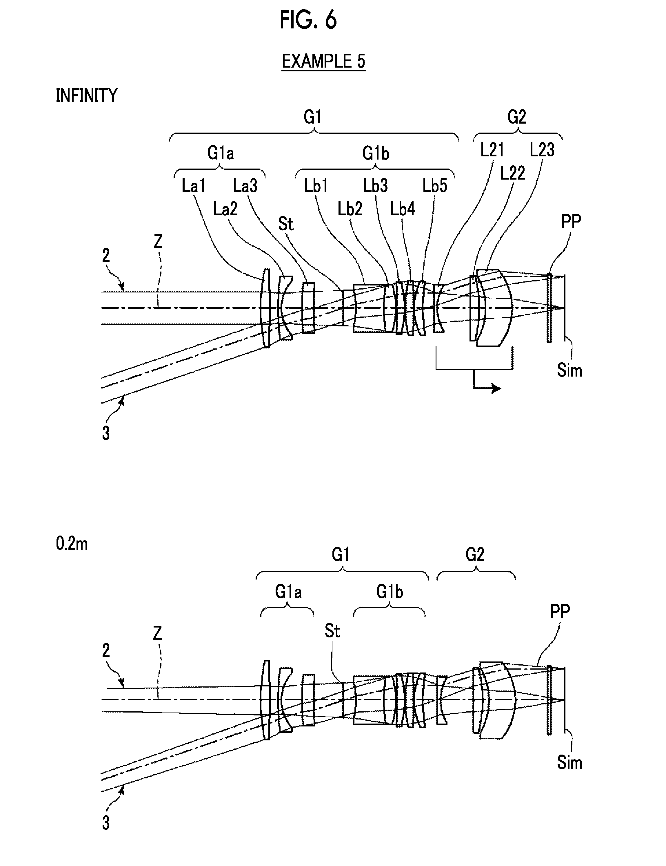
[0024] FIG. 6 is a cross-sectional view illustrating a configuration and an optical path of an imaging lens of Example 5 of the present invention.
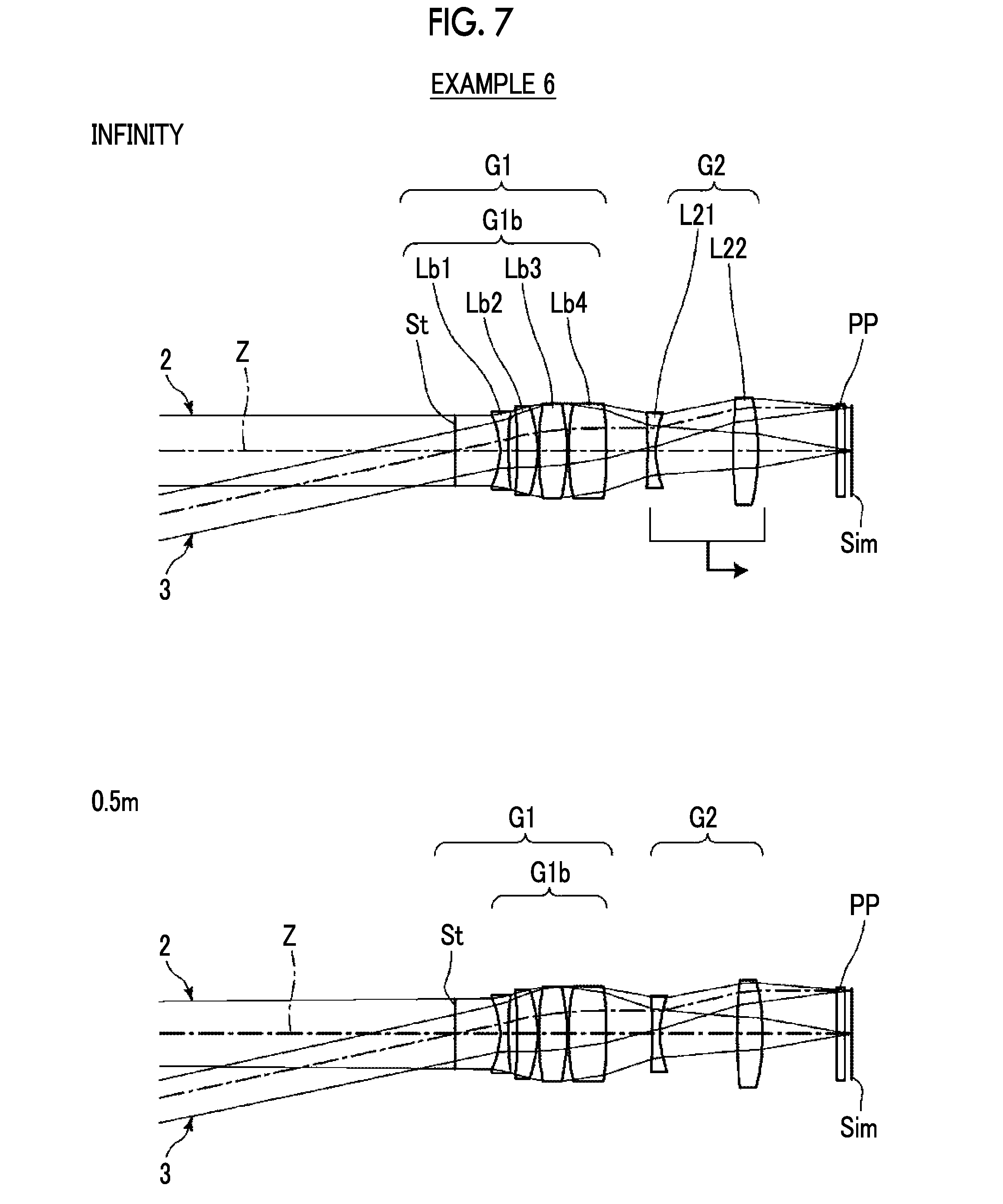
[0025] FIG. 7 is a cross-sectional view illustrating a configuration and an optical path of an imaging lens of Example 6 of the present invention.
[0026] FIG. 8 is a cross-sectional view illustrating a configuration and an optical path of an imaging lens of Example 7 of the present invention.
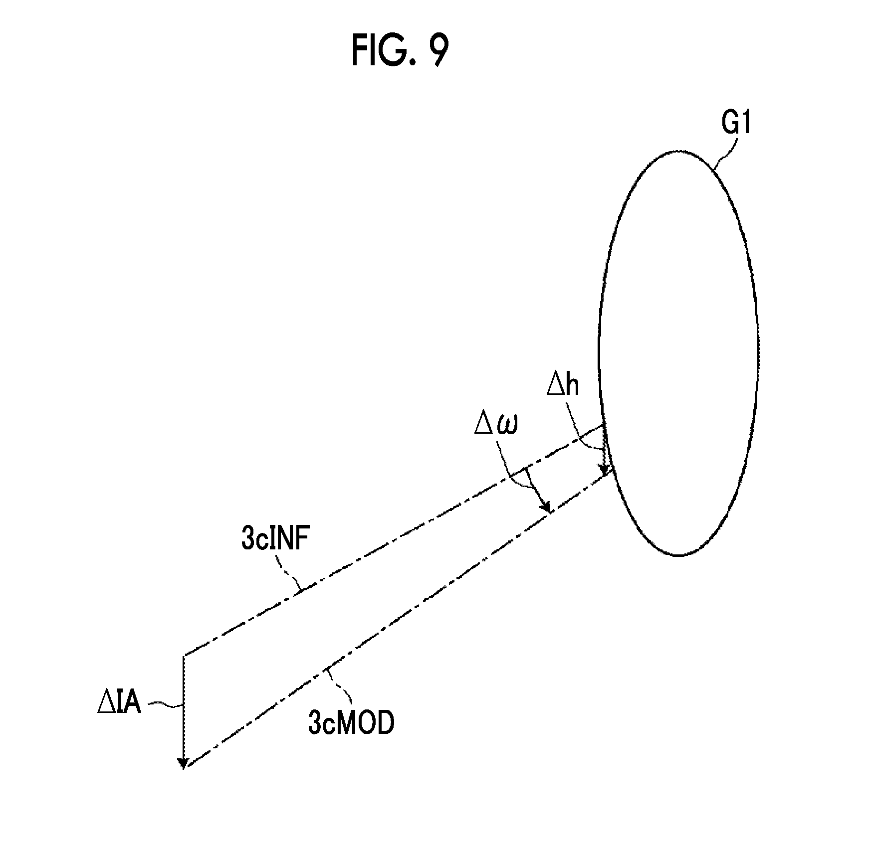
[0027] FIG. 9 is a diagram for explaining change in imaging range during focusing in a conventional imaging lens.
[0028] FIG. 10 is a diagram of aberrations of the imaging lens of Example 1 of the present invention.
[0029] FIG. 11 is a diagram of aberrations of the imaging lens of Example 2 of the present invention.
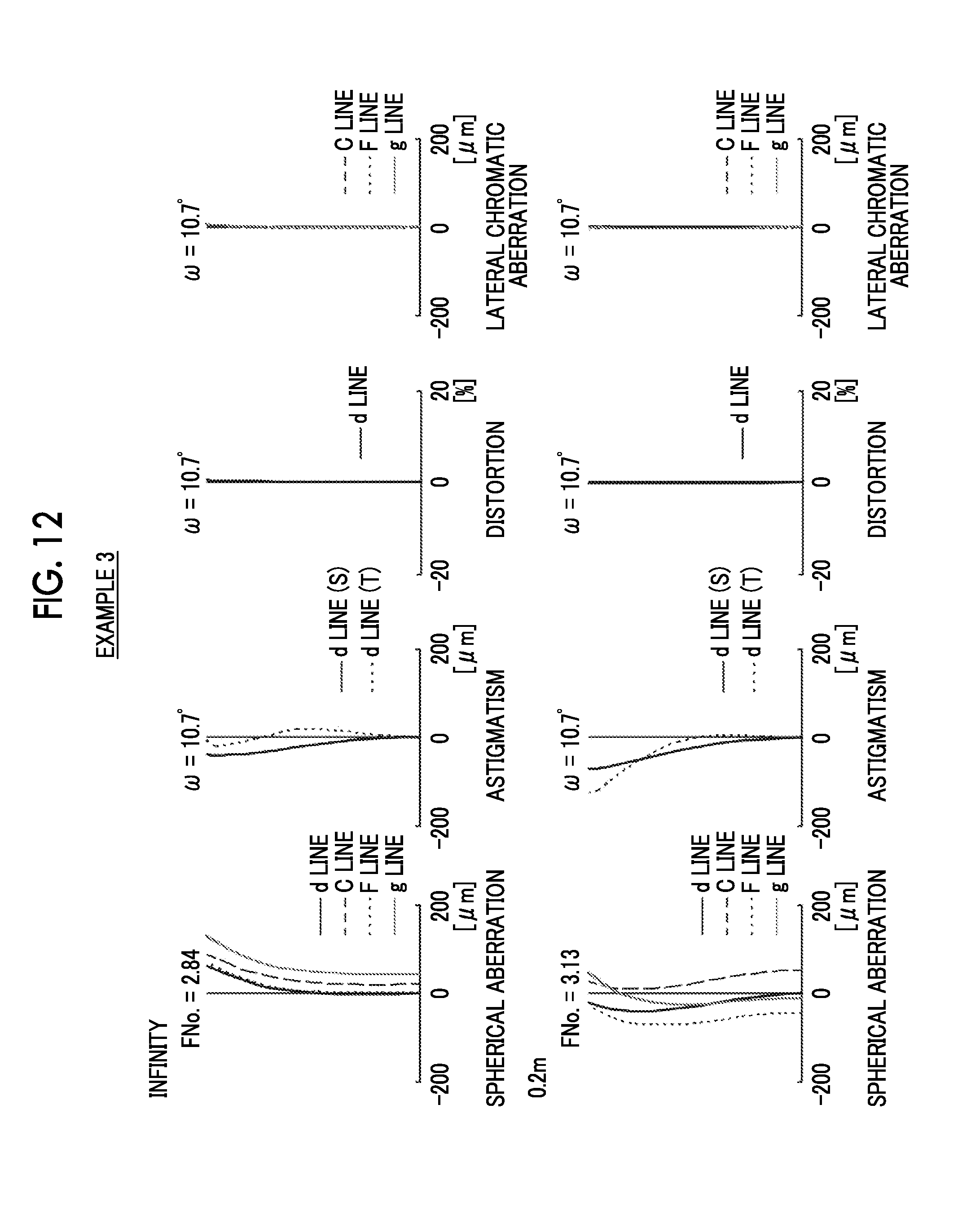
[0030] FIG. 12 is a diagram of aberrations of the imaging lens of Example 3 of the present invention.
[0031] FIG. 13 is a diagram of aberrations of the imaging lens of Example 4 of the present invention.
[0032] FIG. 14 is a diagram of aberrations of the imaging lens of Example 5 of the present invention.
[0033] FIG. 15 is a diagram of aberrations of the imaging lens of Example 6 of the present invention.
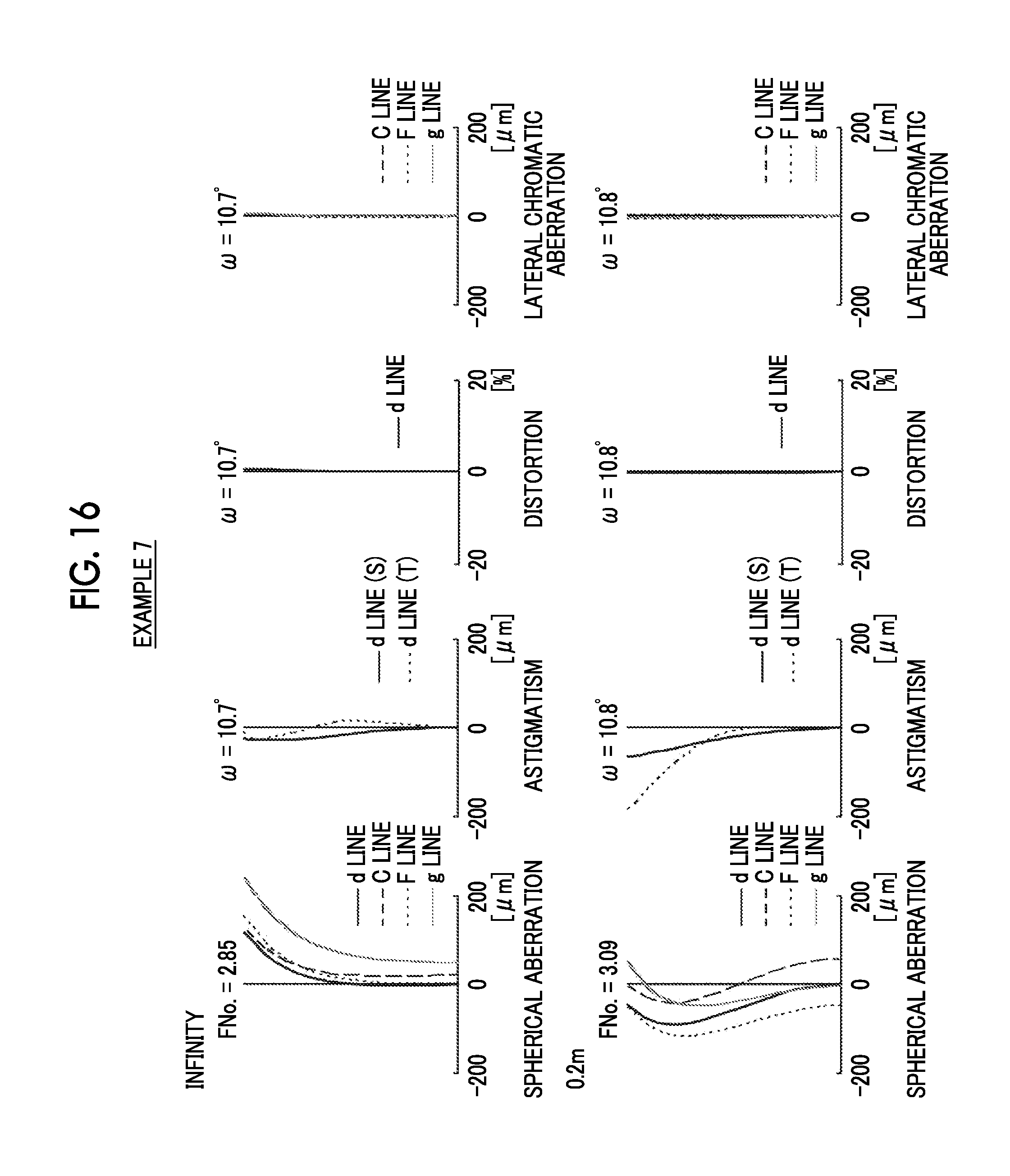
[0034] FIG. 16 is a diagram of aberrations of the imaging lens of Example 7 of the present invention.
[0035] FIG. 17 is a schematic configuration diagram of an imaging apparatus according to an embodiment of the present invention.
DESCRIPTION OF THE PREFERRED EMBODIMENTS
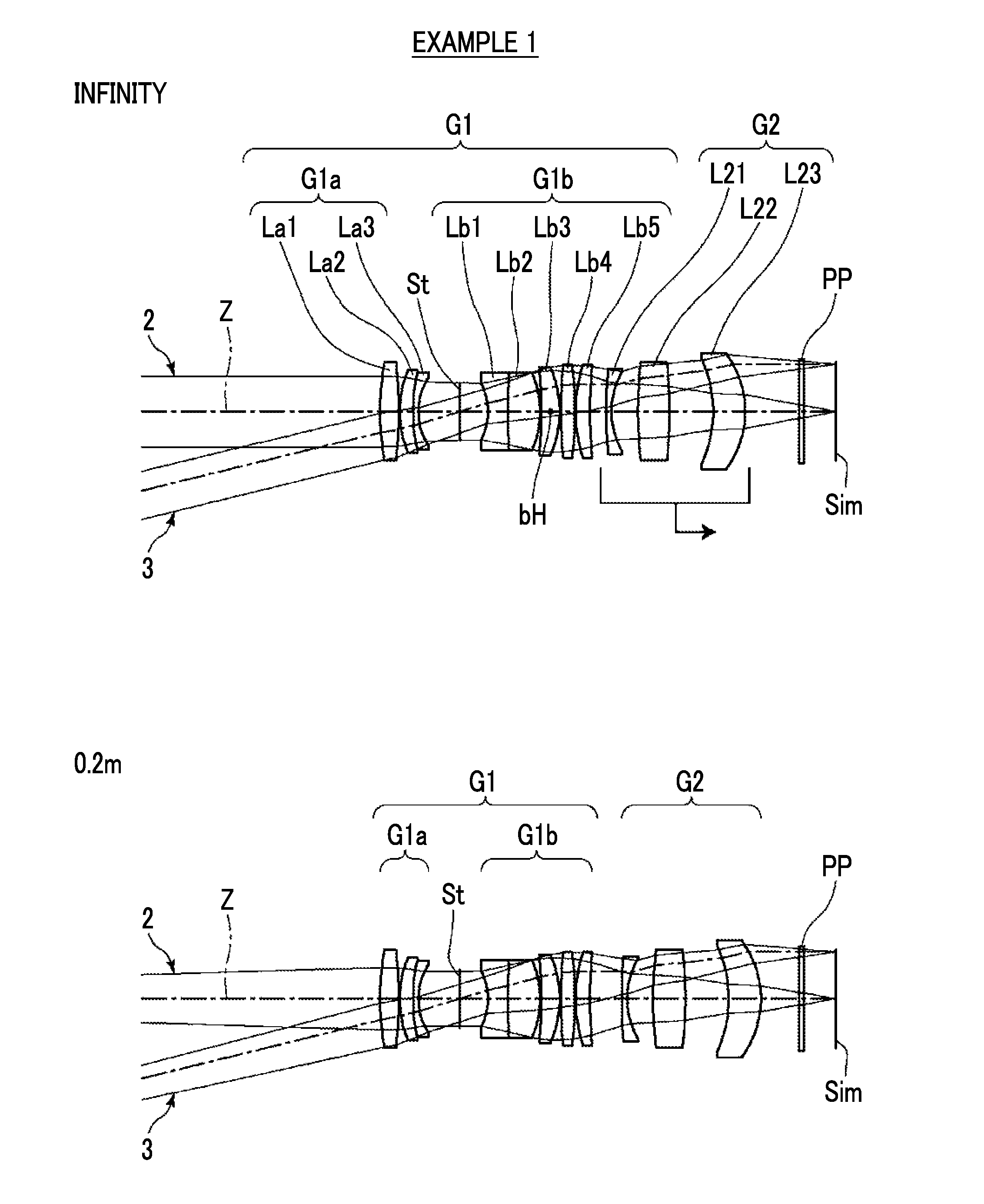
[0036] Hereinafter, embodiments of the present invention will be described with reference to drawings. FIG. 1 is a cross-sectional view illustrating a configuration and an optical path of an imaging lens according to an embodiment of the present invention. The example shown in FIG. 1 corresponds to the imaging lens of Example 1 to be described later. In FIG. 1, the left side thereof is the object side and the right side thereof is the image side, where on-axis rays 2 and rays with the maximum angle of view 3 are shown as optical paths. In FIG. 1, a state where an object at infinity is in focus is shown in the upper part labeled as "infinity", and a state where a close-range object having an object distance of "0.2 m" is in focus is shown in the lower part labeled as "0.2 m (meters)". It should be noted that the object distance is a distance on the optical axis Z from the lens surface, which is closest to the object side, to the object. Likewise, FIGS. 3 to 8 each are a cross-sectional view illustrating a configuration and an optical path of an imaging lens according to an embodiment of the present invention. The examples shown in FIGS. 3 to 8 correspond to the imaging lenses of Examples 2 to 7 to be described later. Basic configurations and methods shown in the drawings of examples shown in FIGS. 1 and 3 to 8 are the same, and will be hereinafter described with reference to mainly the example shown in FIG. 1.
[0037] The imaging lens consists of, in order from the object side to the image side along the optical axis Z: a first lens group G1 that has a positive refractive power and remains stationary with respect to an image plane Sim during focusing; and a second lens group G2 that moves toward the image side during focusing from a distant object to a close-range object. That is, the imaging lens is a rear focus type lens system, and a lens group (hereinafter referred to as a focus lens group), which moves in the direction of the optical axis during focusing, consists of the second lens group G2. The arrow pointing to the right under the second lens group G2 in FIG. 1 means that the second lens group G2 moves to the image side during focusing from the distant object to the close-range object.
[0038] In addition, FIG. 1 shows an example in which an optical member PP having a plane parallel plate shape is disposed between the lens closest to the image side and the image plane Sim. However, the optical member PP may be disposed at a position different from that in the example of FIG. 1, or the optical member PP may be omitted. The optical member PP is assumed to be various filters such as an infrared cut filter and a low pass filter, a cover glass, and the like.
[0039] The first lens group G1 is configured to have, successively in order from a position closest to the image side, a first-b sub-lens group G1b having a positive refractive power and an aperture stop St. That is, since the first lens group G1 has the aperture stop St and the first-b sub-lens group G1b successively in order from the object side to the image side, the first-b sub-lens group G1b is disposed to be closest to the image side in the first lens group G1. It should be noted that the aperture stop St shown in FIG. 1 does not necessarily indicate its size and shape, and indicates a position of the stop on the optical axis Z.
[0040] As in the example shown in FIG. 1, the first lens group G1 may have a lens at a position closer to the object side than the aperture stop St, and as in the example shown in FIG. 7, the first lens group G1 do not have to have a lens at a position closer to the object side than the aperture stop St. In the example of FIG. 1, the first lens group G1 consists of, in order from the object side to the image side, a first-a sub-lens group G1a, the aperture stop St, and the first-b sub-lens group G1b. The first-a sub-lens group G1a consists of three lenses La1 to La3 in order from the object side to the image side. The first-b sub-lens group G1b consists of five lenses Lb1 to Lb5 in order from the object side to the image side. The second lens group G2 consists of three lenses L21 to L23 in order from the object side to the image side.
[0041] The imaging lens of the present embodiment is configured to satisfy Conditional Expressions (1) and (2).
0.5<sbH/f1b<1.5 (1)
-0.2<f/f2<0.2 (2)
[0042] Here, sbH is a distance from the aperture stop to an object side principal point of the first-b sub-lens group,
[0043] f1b is a focal length of the first-b sub-lens group,
[0044] f is a focal length of the whole system, and
[0045] f2 is a focal length of the second lens group.
[0046] All the reference signs used in Conditional Expressions are reference signs in a state where the object at infinity is in focus. The upper part of FIG. 1 shows the object side principal point bH of the first-b sub-lens group G1b. Here, the sign of sbH is positive in a case where the object side principal point bH of the first-b sub-lens group G1b is closer to the image side than the aperture stop St, and negative in a case where it is closer to the object side.
[0047] By satisfying Conditional Expression (1), it is possible to reduce the angle of the principal ray of the off-axis rays, which is emitted from the first lens group G1 and travels toward the second lens group G2, with respect to the optical axis Z. That is, the first lens group G1 can be configured to have high telecentricity on the image side. Further, by satisfying Conditional Expression (2), the second lens group G2 can be configured to be a substantially afocal system.
[0048] Here, in order to facilitate understanding, an optical system will be described with reference to FIG. 2. In the optical system, the first lens group G1 is configured to be telecentric on the image side, the second lens group G2 is configured as an afocal system, an aperture stop St is disposed in the first lens group G1. FIG. 2 is a diagram conceptually showing the optical system. In the optical system shown in FIG. 2, the principal ray 3c, which is incident on the first lens group G1 from the object side, passes through the intersection between the aperture stop St and the optical axis Z in the first lens group G1, and is thereafter emitted as a ray, which is parallel to the optical axis Z, from the first lens group G1. Then, the principal ray 3c, which is incident on the second lens group G2 in parallel with the optical axis Z, is emitted from the second lens group G2 while being parallel to the optical axis Z, and is incident on the image plane Sim. That is, in the optical system shown in FIG. 2, in a case where the principal ray 3c is a ray within the angle of view, regardless of the angle of view of the principal ray 3c in a case where the ray is incident on the first lens group G1, the angle of incidence of the principal ray 3c on the image plane Sim is always 0 degree.
[0049] In the optical system shown in FIG. 2, the principal ray 3c is parallel to the optical axis Z between the second lens group G2 and the image plane Sim. Thus, even in a case where the second lens group G2 as the focus lens group moves in the direction of the optical axis, the principal ray 3c, which is incident onto the second lens group G2 from the object side, remains parallel to the optical axis Z, and its height is also invariant. Therefore, even in a case where the second lens group G2 moves in the direction of the optical axis, the optical path of the principal ray 3c in the first lens group G1 does not change, and the angle and the height of the principal ray 3c incident on the whole system becomes invariant. That is, even in a case where the focus lens group moves in the direction of the optical axis, the relationship between the object height and the image height does not change, and the angle of view does not change either.
[0050] For comparison, FIG. 9 conceptually shows change in the principal ray incident on the first lens group G1 in a case where the focus lens group moves so as to perform focusing from the object at infinity to the close-range object in the conventional imaging lens. The first lens group G1 is a lens group closest to the object side. As shown in FIG. 9, in the conventional imaging lens, the optical paths of the principal ray 3cINF during focusing on the object at infinity and the ray 3cMOD during focusing on the close-range object become different, and the change in angle of view .DELTA..omega. and the change in incident height .DELTA.h occur. As a result, the change in imaging range .DELTA.IA occurs. On the other hand, in the optical system shown in FIG. 2, even in a case where the focus lens group moves, the angle of view and the incident height of the principal ray 3c are invariant. Therefore, the imaging range can be made invariant.
[0051] In the imaging lens of the present embodiment, by satisfying Conditional Expressions (1) and (2), it is possible to realize the optical system of FIG. 2 or an optical system similar to the optical system of FIG. 2. By satisfying Conditional Expression (1), the angle of the principal ray emitted from the first lens group G1 to the second lens group G2 with respect to the optical axis Z becomes small, and it is possible to suppress fluctuation in height of the principal ray, which is incident on the second lens group G2, caused by moving the second lens group G2 as a focus lens group. By satisfying Conditional Expressions (1) and (2), even in a case where the focus lens group moves, it is possible to suppress changes in angle and height of the principal ray incident on the whole system. Therefore, it is possible to suppress fluctuation in angle of view and fluctuation in imaging range. Further, by satisfying Conditional Expressions (1) and (2), even in a case where the focus lens group moves, it is possible to reduce the angle of incidence of the principal ray, which is emitted from the whole imaging lens system, on the image plane Sim at the maximum angle of view.
[0052] In addition, in a case of a configuration in which Conditional Expression (1-1) is satisfied instead of Conditional Expression (1), it is possible to obtain more favorable characteristics. Further, in a case of a configuration in which Conditional Expression (2-1) is satisfied instead of Conditional Expression (2), it is possible to obtain more favorable characteristics.
0.8<sbH/f1b<1.2 (1-1)
-0.1<f/f2<0.1 (2-1)
[0053] Further, it is preferable that the imaging lens satisfies at least one of Conditional Expressions (3) to (7).
0.3<h21/h22<0.8 (3)
0.ltoreq.Ffsr/ds<1 (4)
0.ltoreq.Ff1b/ds<1 (5)
1<Bf/dsp<2 (6)
1<Bf1/d<20 (7)
[0054] Here, h21 is a height of a paraxial on-axis ray at a lens surface closest to the object side in the second lens group,
[0055] h22 is a height of a paraxial on-axis ray at a lens surface closest to the image side in the second lens group,
[0056] Ffsr is an air-converted distance on an optical axis from an object side focal point of a synthetic optical system, which is formed by combining the first-b sub-lens group and the second lens group, to a lens surface closest to the object side in the synthetic optical system,
[0057] ds is a distance on the optical axis from a lens surface closest to the aperture stop at a position closer to the object side than the aperture stop to a lens surface closest to the aperture stop at a position closer to the image side than the aperture stop in a system in which a lens is present to be closer to the object side than the aperture stop and is infinite in a system in a lens is not present to be closer to the object side than the aperture stop,
[0058] Ff1b is an air-converted distance on the optical axis from an object side focal point of the first-b sub-lens group to a lens surface closest to the object side in the first-b sub-lens group,
[0059] Bf is a back focal length of the whole system at an air-converted distance,
[0060] dsp is a distance on the optical axis from a lens surface closest to the aperture stop at a position closer to the object side than the aperture stop to a lens surface closest to the aperture stop at a position closer to the image side than the aperture stop in a system in which a lens is present to be closer to the object side than the aperture stop, and is a distance on the optical axis from the aperture stop to a lens surface closest to the aperture stop at a position closer to the image side than the aperture stop in a system in which a lens is not present to be closer to the object side than the aperture stop,
[0061] Bf1 is a back focal length of the first lens group at an air-converted distance, and
[0062] d is a distance on the optical axis between the first lens group and the second lens group.
[0063] All the reference signs used in Conditional Expressions are reference signs in a state where the object at infinity is in focus. The h21 and h22 comply with the definition in paraxial ray tracing based on "Optical Technology Series 1 Lens Design Method" (Yoshiya Matsui, Kyoritsu Shuppan Co., Ltd.), pp. 19, (2.10)-(2.12). The sign of Ffsr is positive in a case where the lens surface closest to the object side in the above synthetic optical system is closer to the image side than the object side focal point of the synthetic optical system, and the sign is negative in a case where the lens surface is closer to the object side. The sign of Ff1b is positive in a case where the lens surface closest to the object side in the first-b sub-lens group G1b is closer to the image side than the object side focal point of the first-b sub-lens group G1b, and the sign is negative in a case where the lens surface is closer to the object side.
[0064] Hereinafter, each of the above conditional expressions will be described. In a case where the second lens group G2 is an afocal optical system, h21/h22 in Conditional Expression (3) corresponds to the afocal magnification of the second lens group G2. By not allowing the result of Conditional Expression (3) to be equal to or less than the lower limit, it is possible to minimize the total length of the second lens group G2. By not allowing the result of Conditional Expression (3) to be equal to or greater than the upper limit, it is possible to minimize the amount of movement of the focus lens group for focusing and to minimize the total length of the lens system. In addition, in a case of a configuration in which Conditional Expression (3-1) is satisfied instead of Conditional Expression (3), it is possible to obtain more favorable characteristics.
0.4<h21/h22<0.6 (3-1)
[0065] The Ffsr in Conditional Expression (4) corresponds to the front focus of the synthetic optical system formed by combining the first-b sub-lens group G1b and the second lens group G2. In the example of FIG. 1, the ds in Conditional Expression (4) is a distance on the optical axis between the lens surfaces opposed to each other with the aperture stop St interposed therebetween, and is a distance on the optical axis from the image side lens surface of the lens La3 to the object side lens surface of the lens Lb1. However, in the example of FIG. 7, the ds is infinite. By satisfying Conditional Expression (4), it becomes easy to make the whole imaging lens system telecentric on the image side. In addition, in a case of a configuration in which Conditional Expression (4-1) is satisfied instead of Conditional Expression (4), it is possible to obtain more favorable characteristics.
0.ltoreq.Ffsr/ds<0.6 (4-1)
[0066] The Ff1b in Conditional Expression (5) corresponds to the front focus of the first-b sub-lens group G1b. By satisfying Conditional Expression (5), it becomes easy to make the first lens group G1 telecentric on the image side. In addition, in a case of a configuration in which Conditional Expression (5-1) is satisfied, it is possible to obtain more favorable characteristics.
0.ltoreq.Ff1b/ds<0.6 (5-1)
[0067] In the example of FIG. 1, the dsp in Conditional Expression (6) is a distance on the optical axis between the lens surfaces opposed to each other with the aperture stop St interposed therebetween, and is a distance on the optical axis from the image side lens surface of the lens La3 to the object side lens surface of the lens Lb1. However, in the example of FIG. 7, dsp is a distance on the optical axis from the aperture stop St to the object side lens surface of the lens Lb1. By not allowing the result of Conditional Expression (6) to be equal to or less than the lower limit, it is possible to ensure a distance between the imaging lens and the imaging element, and it becomes easy to construct a mechanical structure in the imaging apparatus. By not allowing the result of Conditional Expression (6) to be equal to or greater than the upper limit, the total length of the lens system can be prevented from becoming excessively long. In addition, in a case of a configuration in which Conditional Expression (6-1) is satisfied, it is possible to obtain more favorable characteristics.
1.2<Bf/dsp<2 (6-1)
[0068] By not allowing the result of Conditional Expression (7) to be equal to or less than the lower limit, it is possible to adopt a configuration in which a primary image is formed between the first lens group G1 and the second lens group G2, and thus the function of the focus lens group can be fulfilled. By not allowing the result of Conditional Expression (7) to be equal to or greater than the upper limit, it becomes easy to ensure the F number to the extent practically required. In addition, in a case of a configuration in which Conditional Expression (7-1) is satisfied, it is possible to obtain more favorable characteristics.
2<Bf1/d<15 (7-1)
[0069] The above-mentioned preferred configurations and available configurations may be optional combinations, and it is preferable to selectively adopt the configurations in accordance with required specification. According to the present embodiment, it is possible to realize an imaging lens which has a small angle of incidence of the principal ray on the image plane Sim at the maximum angle of view regardless of an imaging distance and small fluctuation in imaging range caused by moving a focus lens group so as to have favorable performance. Further, the term "the small angle of incidence of the principal ray onto the image plane Sim at the maximum angle of view" means that the angle formed by the perpendicular of the image plane Sim and the principal ray at the maximum angle of view is in a range of -5.degree. to +5.degree.. Further, the "movement of the focus lens group" is not limited only to the focusing operation in a case where the object distance fluctuates, but also includes, for example, the movement of the focus lens group due to vibration.
[0070] Next, numerical examples of the imaging lens of the present invention will be described.
Example 1
[0071] FIG. 1 shows a cross-sectional view of an imaging lens of Example 1, and an illustration method thereof is as described above. Therefore, repeated description is partially omitted herein. The imaging lens of Example 1 consists of, in order from the object side to the image side, a first lens group G1 having a positive refractive power and a second lens group G2 having a positive refractive power. During focusing from a distant object to a close-range object, the first lens group G1 remains stationary with respect to the image plane Sim, and the second lens group G2 moves toward the image side. The first lens group G1 consists of, in order from the object side to the image side, a first-a sub-lens group G1a, an aperture stop St, and a first-b sub-lens group G1b. The first-a sub-lens group G1a consists of three lenses La1 to La3 in order from the object side to the image side. The first-b sub-lens group G1b consists of five lenses Lb1 to Lb5 in order from the object side to the image side. The second lens group G2 consists of three lenses L21 to L23 in order from the object side to the image side.
[0072] Table 1 shows basic lens data of the imaging lens of Example 1, and Table 2 shows specification and variable surface distances. In Table 1, the column of the surface number shows surface numbers. The surface closest to the object side is the first surface, and the surface numbers increase one by one toward the image side. The column of R shows radii of curvature of the respective surfaces. The column of D shows surface distances on the optical axis between the respective surfaces and the surfaces adjacent to the image side. Further, the column of Nd shows refractive indexes of the respective components at the d line (a wavelength of 587.6 nm (nanometers)), and the column of .nu.d shows Abbe numbers of the respective components at the d line.
[0073] In Table 1, reference signs of radii of curvature of surface shapes convex toward the object side are set to be positive, and reference signs of radii of curvature of surface shapes convex toward the image side are set to be negative. Table 1 additionally shows the aperture stop St and the optical member PP. In Table 1, in a place of a surface number of a surface corresponding to the aperture stop St, the surface number and a term of (St) are noted. A value at the bottom place of D in Table 1 indicates a distance between the image plane Sim and the surface closest to the image side in the table. In Table 1, the variable surface distances are referenced by the reference signs DD[ ], and are written into places of D, where object side surface numbers of distances are noted in [ ].
[0074] Table 2 shows the focal length f of the whole system in a state where the object at infinity is in focus, the focal length fnear of the whole system in a state where an object having an object distance of 0.2 m (meters) is in focus, and the back focal length Bf of the whole system at the air-converted distance in the state where the object at infinity is in focus. In Table 2, values of the F number FNo., the maximum total angle of view 2.omega., and the variable surface distance in the state where the object at infinity is in focus and the state where the object having the object distance of 0.2 m (meters) is in focus are based on the d line.)(.degree. in the place of 2.omega. indicates that the unit thereof is a degree. In Table 2, the column denoted by the "infinity" shows respective values thereof in a state where the object at infinity is in focus, and the column denoted by "0.2 m" shows respective values thereof in a state where an object at an object distance of 0.2 m (meters) is in focus.
[0075] In data of each table, a degree is used as a unit of an angle, and mm (millimeter) is used as a unit of a length, but appropriate different units may be used since the optical system can be used even in a case where the system is enlarged or reduced in proportion. Further, each of the following tables shows numerical values rounded off to predetermined decimal places.
TABLE-US-00001 TABLE 1 Example 1 Surface Number R D Nd .nu.d 1 57.89274 3.435 1.51999 64.23 2 -91.36596 0.200 3 19.96400 2.476 1.79585 25.21 4 31.99641 1.010 1.51999 64.23 5 11.53491 7.781 6 (St) .infin. 5.177 7 -11.27270 3.731 1.73379 31.54 8 151.21396 6.010 1.53775 74.70 9 -17.96795 0.200 10 -91.95969 3.453 1.59522 67.73 11 -20.48590 0.200 12 79.82503 2.601 1.71152 55.92 13 -85.68681 0.200 14 28.17225 2.632 1.68207 57.40 15 86.89963 DD[15] 16 109.40601 1.000 1.84999 28.91 17 15.10055 4.914 18 77.82159 6.000 1.85001 22.50 19 -84.59731 8.155 20 -23.53324 6.000 1.68437 38.46 21 -18.19205 DD[21] 22 .infin. 1.000 1.51680 64.20 23 .infin. 6.105
TABLE-US-00002 TABLE 2 Example 1 Infinity 0.2 m f 36.013 -- fnear -- 36.098 Bf 16.764 -- FNo. 2.72 2.90 2.omega. (.degree.) 28.6 28.6 DD[15] 3.083 6.030 DD[21] 10.000 7.053
[0076] FIG. 10 shows a diagram of aberrations of the imaging lens of Example 1. In FIG. 10, in order from the left side, spherical aberration, astigmatism, distortion, and lateral chromatic aberration are shown. In FIG. 10, a state where an object at infinity is in focus is shown in the upper part labeled as "infinity", and a state where a close-range object having an object distance of "0.2 m" is in focus is shown in the lower part labeled as "0.2 m (meters)". In the spherical aberration diagram, aberrations at the d line (a wavelength of 587.6 nm (nanometers)), the C line (a wavelength of 656.3 nm (nanometers)), the F line (a wavelength of 486.1 nm (nanometers)), and the g line (a wavelength of 435.8 nm (nanometers)) are respectively indicated by the solid line, the long dashed line, the short dashed line, and the gray solid line. In the astigmatism diagram, aberration in the sagittal direction at the d line is indicated by the solid line, and aberration in the tangential direction at the d line is indicated by the short dashed line. In the distortion diagram, aberration at the d line is indicated by the solid line. In the lateral chromatic aberration diagram, aberrations at the C line, the F line, and the g line are respectively indicated by the long dashed line, the short dashed line, and the gray solid line. In the spherical aberration diagram, FNo. indicates an F number. In the other aberration diagrams, .omega. indicates a half angle of view.
[0077] The symbols, the meanings, the description method, and the illustration method of each data relating to the above-mentioned imaging lens of Example 1 are the same in Examples unless otherwise specified. Therefore, repeated examples will be omitted below.
Example 2
[0078] FIG. 3 is a cross-sectional view of an imaging lens of Example 2. The imaging lens of Example 2 consists of, in order from the object side to the image side, a first lens group G1 having a positive refractive power and a second lens group G2 having a positive refractive power. During focusing from a distant object to a close-range object, the first lens group G1 remains stationary with respect to the image plane Sim, and the second lens group G2 moves toward the image side. The first lens group G1 consists of, in order from the object side to the image side, a first-a sub-lens group G1a, an aperture stop St, and a first-b sub-lens group G1b. The first-a sub-lens group G1a consists of three lenses La1 to La3 in order from the object side to the image side. The first-b sub-lens group G1b consists of five lenses Lb1 to Lb5 in order from the object side to the image side. The second lens group G2 consists of three lenses L21 to L23 in order from the object side to the image side. Table 3 shows basic lens data of the imaging lens of Example 2, Table 4 shows specification and variable surface distances, and FIG. 11 shows aberration diagrams thereof.
TABLE-US-00003 TABLE 3 Example 2 Surface Number R D Nd .nu.d 1 25.47686 4.092 1.72551 55.22 2 261.86195 0.200 3 19.99278 2.292 1.84399 23.12 4 27.90409 1.045 1.54686 53.35 5 11.34321 5.271 6 (St) .infin. 5.827 7 -13.79559 1.317 1.82324 23.84 8 42.11701 5.017 1.49700 81.54 9 -22.86594 2.875 10 -74.51508 2.908 1.82996 44.51 11 -23.92404 0.200 12 170.09040 2.257 1.76358 51.64 13 -81.78636 0.200 14 41.09769 3.049 1.74595 53.41 15 -103.05031 DD[15] 16 69.71212 1.000 1.85001 37.48 17 13.28087 4.388 18 103.15745 2.702 1.85001 22.50 19 -83.40264 10.041 20 -20.56924 6.000 1.83313 44.69 21 -16.89828 DD[21] 22 .infin. 1.000 1.51680 64.20 23 .infin. 7.047
TABLE-US-00004 TABLE 4 Example 2 Infinity 0.2 m f 48.503 -- fnear -- 48.599 Bf 17.706 -- FNo. 2.86 3.14 2.omega. (.degree.) 21.4 21.4 DD[15] 1.675 6.161 DD[21] 10.000 5.514
Example 3
[0079] FIG. 4 is a cross-sectional view of an imaging lens of Example 3. The imaging lens of Example 3 consists of, in order from the object side to the image side, a first lens group G1 having a positive refractive power and a second lens group G2 having a positive refractive power. During focusing from a distant object to a close-range object, the first lens group G1 remains stationary with respect to the image plane Sim, and the second lens group G2 moves toward the image side. The first lens group G1 consists of, in order from the object side to the image side, a first-a sub-lens group G1a, an aperture stop St, and a first-b sub-lens group G1b. The first-a sub-lens group G1a consists of three lenses La1 to La3 in order from the object side to the image side. The first-b sub-lens group G1b consists of five lenses Lb1 to Lb5 in order from the object side to the image side. The second lens group G2 consists of three lenses L21 to L23 in order from the object side to the image side. Table 5 shows basic lens data of the imaging lens of Example 3, Table 6 shows specification and variable surface distances, and FIG. 12 shows aberration diagrams thereof.
TABLE-US-00005 TABLE 5 Example 3 Surface Number R D Nd .nu.d 1 22.93229 4.641 1.56585 42.65 2 533.63772 0.200 3 20.17950 2.904 1.69228 56.89 4 44.42156 1.010 1.54934 55.62 5 11.03562 5.417 6 (St) .infin. 6.563 7 -11.33070 3.643 1.80490 32.24 8 119.54281 4.318 1.49700 81.54 9 -18.52930 1.061 10 -119.93787 3.929 1.59522 67.73 11 -18.43767 0.200 12 86.60998 2.464 1.70508 56.25 13 -99.34469 0.200 14 31.56318 2.578 1.70483 56.26 15 120.87796 DD[15] 16 53.75975 1.000 1.90366 31.31 17 13.86273 4.525 18 108.54421 2.470 1.95906 17.47 19 -117.86384 11.379 20 -22.57280 6.000 1.74697 53.30 21 -17.35146 DD[21] 22 .infin. 1.000 1.51680 64.20 23 .infin. 7.432
TABLE-US-00006 TABLE 6 Example 3 Infinity 0.2 m f 48.504 -- fnear -- 48.600 Bf 18.091 -- FNo. 2.84 3.13 2.omega. (.degree.) 21.4 21.4 DD[15] 2.432 7.110 DD[21] 10.000 5.322
Example 4
[0080] FIG. 5 is a cross-sectional view of an imaging lens of Example 4. The imaging lens of Example 4 consists of, in order from the object side to the image side, a first lens group G1 having a positive refractive power and a second lens group G2 having a positive refractive power. During focusing from a distant object to a close-range object, the first lens group G1 remains stationary with respect to the image plane Sim, and the second lens group G2 moves toward the image side. The first lens group G1 consists of, in order from the object side to the image side, a first-a sub-lens group G1a, an aperture stop St, and a first-b sub-lens group G1b. The first-a sub-lens group G1a consists of one lens La1. The first-b sub-lens group G1b consists of three lenses Lb1 to Lb3 in order from the object side to the image side. The second lens group G2 consists of two lenses L21 and L22 in order from the object side to the image side. Table 7 shows basic lens data of the imaging lens of Example 4, Table 8 shows specification and variable surface distances, and FIG. 13 shows aberration diagrams thereof. FIG. 5, Table 8, and FIG. 13 show data representing a state, in which the object at infinity is in focus, and a state in which an object having an object distance of 0.5 m (meters) is in focus.
TABLE-US-00007 TABLE 7 Example 4 Surface Number R D Nd .nu.d 1 16.48350 4.241 1.73505 54.50 2 93.10077 5.424 3 (St) .infin. 3.264 4 -23.89481 3.836 1.71553 29.22 5 10.90260 1.081 6 25.69589 3.729 1.59522 67.73 7 -23.77895 5.928 8 40.93421 3.629 1.85001 41.92 9 -22.85744 DD[9] 10 -22.19668 1.000 1.85000 43.00 11 13.67892 5.387 12 74.35211 4.873 1.65733 49.13 13 -13.58435 DD[13] 14 .infin. 1.000 1.51680 64.20 15 .infin. 2.236
TABLE-US-00008 TABLE 8 Example 4 Infinity 0.5 m f 48.471 -- fnear -- 48.569 Bf 12.895 -- FNo. 2.86 2.88 2.omega. (.degree.) 13.4 13.4 DD[9] 2.362 4.353 DD[13] 10.000 8.009
Example 5
[0081] FIG. 6 is a cross-sectional view of an imaging lens of Example 5. The imaging lens of Example 5 consists of, in order from the object side to the image side, a first lens group G1 having a positive refractive power and a second lens group G2 having a positive refractive power. During focusing from a distant object to a close-range object, the first lens group G1 remains stationary with respect to the image plane Sim, and the second lens group G2 moves toward the image side. The first lens group G1 consists of, in order from the object side to the image side, a first-a sub-lens group G1a, an aperture stop St, and a first-b sub-lens group G1b. The first-a sub-lens group G1a consists of three lenses La1 to La3 in order from the object side to the image side. The first-b sub-lens group G1b consists of five lenses Lb1 to Lb5 in order from the object side to the image side. The second lens group G2 consists of three lenses L21 to L23 in order from the object side to the image side. Table 9 shows basic lens data of the imaging lens of Example 5, Table 10 shows specification and variable surface distances, and FIG. 14 shows aberration diagrams thereof.
TABLE-US-00009 TABLE 9 Example 5 Surface Number R D Nd .nu.d 1 53.45838 2.480 1.80610 40.93 2 -566.43434 2.330 3 58.98162 1.000 1.53775 74.70 4 11.45178 5.703 5 60.18258 3.390 1.91865 19.07 6 375.07745 8.257 7 (St) .infin. 3.522 8 -17.73423 7.776 1.73492 39.00 9 50.10187 3.397 1.59522 67.73 10 -20.49550 0.200 11 -620.83841 2.219 1.75202 52.80 12 -27.63137 0.200 13 33.45951 2.300 1.53618 74.43 14 -189.93249 0.200 15 17.48574 2.417 1.52139 76.71 16 46.71096 DD[16] 17 238.16661 1.000 1.85000 22.50 18 12.50698 9.272 19 -3719.28107 2.531 1.95906 17.47 20 -33.97888 1.780 21 -18.04970 7.396 1.65046 41.59 22 -16.90555 DD[22] 23 .infin. 1.000 1.51680 64.20 24 .infin. 3.848
TABLE-US-00010 TABLE 10 Example 5 Infinity 0.2 m f 25.756 -- fnear -- 25.778 Bf 14.508 -- FNo. 2.82 2.90 2.omega. (.degree.) 39.0 39.2 DD[16] 3.130 4.068 DD[22] 10.000 9.062
Example 6
[0082] FIG. 7 is a cross-sectional view of an imaging lens of Example 6. The imaging lens of Example 6 consists of, in order from the object side to the image side, a first lens group G1 having a positive refractive power and a second lens group G2 having a positive refractive power. During focusing from a distant object to a close-range object, the first lens group G1 remains stationary with respect to the image plane Sim, and the second lens group G2 moves toward the image side. The first lens group G1 consists of an aperture stop St and a first-b sub-lens group G1b in order from the object side to the image side. That is, the imaging lens of Example 6 is a system in which no lens is present at a position closer to the object side than the aperture stop St. The first-b sub-lens group G1b consists of four lenses Lb1 to Lb4 in order from the object side to the image side. The second lens group G2 consists of two lenses L21 and L22 in order from the object side to the image side. Table 11 shows basic lens data of the imaging lens of Example 6, Table 12 shows specification and variable surface distances, and FIG. 15 shows aberration diagrams thereof. FIG. 7, Table 12, and FIG. 15 show data representing a state, in which the object at infinity is in focus, and a state in which an object having an object distance of 0.5m (meters) is in focus.
TABLE-US-00011 TABLE 11 Example 6 Surface Number R D Nd .nu.d 1 (St) .infin. 5.805 2 -10.09399 1.025 1.57927 40.14 3 32.03424 1.204 4 -56.97976 2.527 1.82180 45.82 5 -16.50326 0.200 6 35.91542 3.578 1.70200 56.40 7 -25.72621 0.200 8 30.30771 4.873 1.60298 61.04 9 -39.17185 DD[9] 10 -65.61842 1.000 1.82407 23.83 11 13.08880 9.775 12 70.40420 3.235 1.85000 41.31 13 -28.01034 DD[13] 14 .infin. 1.000 1.51680 64.20 15 .infin. 0.860
TABLE-US-00012 TABLE 12 Example 6 Infinity 0.5 m f 25.512 -- fnear -- 25.542 Bf 11.520 -- FNo. 2.83 2.88 2.omega. (.degree.) 25.6 25.6 DD[9] 5.293 5.838 DD[13] 10.000 9.455
Example 7
[0083] FIG. 8 is a cross-sectional view of an imaging lens of Example 7. The imaging lens of Example 7 consists of, in order from the object side to the image side, a first lens group G1 having a positive refractive power and a second lens group G2 having a negative refractive power. During focusing from a distant object to a close-range object, the first lens group G1 remains stationary with respect to the image plane Sim, and the second lens group G2 moves toward the image side. The first lens group G1 consists of, in order from the object side to the image side, a first-a sub-lens group G1a, an aperture stop St, and a first-b sub-lens group G1b. The first-a sub-lens group G1a consists of three lenses La1 to La3 in order from the object side to the image side. The first-b sub-lens group G1b consists of four lenses Lb1 to Lb4 in order from the object side to the image side. The second lens group G2 consists of three lenses L21 to L23 in order from the object side to the image side. Table 13 shows basic lens data of the imaging lens of Example 7, Table 14 shows specification and variable surface distances, and FIG. 16 shows aberration diagrams thereof.
TABLE-US-00013 TABLE 13 Example 7 Surface Number R D Nd .nu.d 1 34.19932 5.289 1.71833 32.38 2 -1096.63098 0.200 3 20.75365 3.808 1.59522 67.73 4 34.84796 1.078 1.51999 64.23 5 11.96163 5.094 6 (St) .infin. 5.861 7 -13.46203 3.719 1.77171 27.93 8 51.61499 6.010 1.59522 67.73 9 -17.97847 3.024 10 25135.40670 6.000 1.80618 47.38 11 -32.02550 0.200 12 30.89268 2.853 1.74995 53.01 13 325.22326 DD[13] 14 78.69690 1.000 1.98929 23.17 15 15.24617 4.344 16 54.18708 6.000 2.00001 15.00 17 -335.09932 8.722 18 -22.57582 6.000 1.80853 36.27 19 -18.30600 DD[19] 20 .infin. 1.000 1.51680 64.20 21 .infin. 7.743
TABLE-US-00014 TABLE 14 Example 7 Infinity 0.2 m f 48.509 -- fnear -- 48.113 Bf 18.402 -- FNo. 2.85 3.09 2.omega. (.degree.) 21.4 21.6 DD[13] 2.407 7.137 DD[19] 10.000 5.270
[0084] Table 15 shows values corresponding to Conditional Expressions (1) to (7) of the imaging lenses of Examples 1 to 7. In Examples 1 to 7, the d line is set as the reference wavelength. Table 15 shows the values on the d line basis.
TABLE-US-00015 TABLE 15 Expression Conditional Example Example Example Example Example Example Example Number Expression 1 2 3 4 5 6 7 (1) sbH/f1b 0.97 0.97 0.98 0.97 1.13 0.97 1.02 (2) f/f2 0.017 0.012 0.011 0.027 0.011 0.030 -0.047 (3) h21/h22 0.570 0.537 0.546 0.547 0.485 0.542 0.557 (4) Ffsr/ds 0.417 0.558 0.572 0.409 0.032 0.000 0.564 (5) Ff1b/ds 0.435 0.573 0.586 0.450 0.487 0.000 0.505 (6) Bf/dsp 1.294 1.596 1.510 1.485 1.245 1.985 1.680 (7) Bf1/d 6.612 10.770 8.224 4.725 10.770 2.898 8.141
[0085] Next, an imaging apparatus according to an embodiment of the present invention will be described. FIG. 17 is a schematic configuration diagram of an imaging apparatus 10 using the imaging lens 1 according to the above-mentioned embodiment of the present invention as an example of an imaging apparatus of an embodiment of the present invention. As the imaging apparatus 10, for example, there is an FA camera, a MV camera, or a surveillance camera.
[0086] The imaging apparatus 10 comprises: the imaging lens 1; a filter 4 that is disposed on the image side of the imaging lens 1; an imaging element 5; a signal processing section 6 that performs processing of calculating a signal which is output from the imaging element 5, and a focus control section 7 that is for performing focusing of the imaging lens 1. FIG. 17 schematically shows the first lens group G1 and the second lens group G2 which are belonging to the imaging lens 1. The imaging element 5 captures an image of a subject, which is formed through the imaging lens 1, and converts the image into an electrical signal. For example, CCD, CMOS, or the like may be used. The imaging element 5 is disposed such that the imaging surface thereof is coplanar with the image plane of the imaging lens 1. Since the imaging apparatus 10 comprises the imaging lens 1 according to the embodiment of the present invention, fluctuation in imaging range caused by focusing is small, and a favorable image can be acquired regardless of the imaging distance.
[0087] The present invention has been hitherto described through embodiments and examples, but the present invention is not limited to the above-mentioned embodiments and examples, and may be modified into various forms. For example, values such as the radius of curvature, the surface distance, the refractive index, and the Abbe number of each lens are not limited to the values shown in the numerical examples, and different values may be used therefor.
[0088] For example, in each example, the lens system, which performs focusing from the infinite distance object to the close-range object, is used. However, it is needless to say that the present invention can be applied to an imaging lens which performs focusing from a distant object at a finite distance to a close-range object.
[0089] The imaging apparatus according to the above-mentioned embodiment of the present invention is not limited to the above-mentioned examples, and may be modified into various forms such as a digital camera and an in-vehicle camera.
* * * * *
D00000
D00001
D00002
D00003
D00004
D00005
D00006
D00007
D00008
D00009
D00010
D00011
D00012
D00013

D00014

D00015

D00016
D00017

XML
uspto.report is an independent third-party trademark research tool that is not affiliated, endorsed, or sponsored by the United States Patent and Trademark Office (USPTO) or any other governmental organization. The information provided by uspto.report is based on publicly available data at the time of writing and is intended for informational purposes only.
While we strive to provide accurate and up-to-date information, we do not guarantee the accuracy, completeness, reliability, or suitability of the information displayed on this site. The use of this site is at your own risk. Any reliance you place on such information is therefore strictly at your own risk.
All official trademark data, including owner information, should be verified by visiting the official USPTO website at www.uspto.gov. This site is not intended to replace professional legal advice and should not be used as a substitute for consulting with a legal professional who is knowledgeable about trademark law.