Device For Determining Petrophysical Parameters Of An Underground Formation
CEREPI; Adrian ; et al.
U.S. patent application number 16/089909 was filed with the patent office on 2019-03-21 for device for determining petrophysical parameters of an underground formation. The applicant listed for this patent is IFP Energies nouvelles. Invention is credited to Adrian CEREPI, Herve DESCHAMPS, Bruno GARCIA.
| Application Number | 20190086350 16/089909 |
| Document ID | / |
| Family ID | 56008797 |
| Filed Date | 2019-03-21 |


| United States Patent Application | 20190086350 |
| Kind Code | A1 |
| CEREPI; Adrian ; et al. | March 21, 2019 |
DEVICE FOR DETERMINING PETROPHYSICAL PARAMETERS OF AN UNDERGROUND FORMATION
Abstract
The invention relates to a device for determining petrophysical parameters of an underground formation, comprising at least two electrodes (EL), a means for emitting a frequency-variable electric current (MEC), and a means for measuring electrical resistivity (MRE) in terms of amplitude and phase, two of the electrodes (EL) cooperating with the emission means (MEC) and at least two of the electrodes (EL) cooperating with the means for measuring resistivity (MRE), a means for measuring a difference in electrical potential (MDP) cooperating with at least two of the electrodes (EL). The invention is particularly applicable to oil exploration and development.
| Inventors: | CEREPI; Adrian; (PESSAC, FR) ; DESCHAMPS; Herve; (NOISY LE ROI, FR) ; GARCIA; Bruno; (RUEIL MALMAISON, FR) | ||||||||||
| Applicant: |
|
||||||||||
|---|---|---|---|---|---|---|---|---|---|---|---|
| Family ID: | 56008797 | ||||||||||
| Appl. No.: | 16/089909 | ||||||||||
| Filed: | March 10, 2017 | ||||||||||
| PCT Filed: | March 10, 2017 | ||||||||||
| PCT NO: | PCT/EP2017/055695 | ||||||||||
| 371 Date: | September 28, 2018 |
| Current U.S. Class: | 1/1 |
| Current CPC Class: | G01N 27/026 20130101; G01V 3/24 20130101; G01V 3/26 20130101 |
| International Class: | G01N 27/02 20060101 G01N027/02; G01V 3/24 20060101 G01V003/24; G01V 3/26 20060101 G01V003/26 |
Foreign Application Data
| Date | Code | Application Number |
|---|---|---|
| Apr 1, 2016 | FR | 1652871 |
Claims
1.-17. (canceled)
18. A device for determining petrophysical parameters of a portion of an underground formation comprising a fluid, comprising: at least two electrodes; means for emitting a variable-frequency electrical current and a means for measuring the electrical resistivity in terms of amplitude and phase, two of the electrodes cooperating with the means for emitting and at least two of the electrodes cooperating with the means for measuring resistivity; means for measuring an electrical potential difference coupled with at least two of the electrodes; and means for automating at least one of measurements performed by the means for measuring, means for collecting the measurements and means for analyzing the measurements.
19. The device as claimed in claim 18, wherein frequencies of the electrical current are within a range of frequencies having a lower limit between 1 and 20 mHz, and an upper limit between 28 and 32 MHz.
20. The device as claimed in claim 18, wherein the electrodes comprise nonpolarizable metal material.
21. The device as claimed in claim 19, wherein the electrodes comprise nonpolarizable metal material.
22. The device as claimed in claim 18, wherein a number of the electrodes ranges between 4 and 8.
23. The device as claimed in claim 19, wherein a number of the electrodes ranges between 4 and 8.
24. The device as claimed in claim 18, wherein the electrodes are distributed over a length of a support formed from an insulating material.
25. The device as claimed in claim 19, wherein the electrodes are distributed over a length of a support formed from an insulating material.
26. The device as claimed in claim 20, wherein the electrodes are distributed over a length of a support formed from an insulating material.
27. The device as claimed in claim 24, wherein the device comprises means for making laboratory measurements and wherein the portion of the formation is a core sample of the formation; the support is a flexible sleeve of cylindrical shape for receiving the sample; at least four electrodes with two of the electrodes contacting each of the free cross sections of the sample; and the length of the support is oriented along an axis of revolution of the support.
28. The device as claimed in claim 27, wherein the sleeve is a heat-shrinkable sheath and at least two of the electrodes pass through the sheath.
29. The device as claimed in claim 27, comprising means for injecting a working fluid into the sample and for regulating a flow rate of the working fluid, and a means for measuring fluid pressure in at least two locations of the sample.
30. The device as claimed in claim 28, comprising means for injecting a working fluid into the sample and for regulating a flow rate of the working fluid, and a means for measuring fluid pressure in at least two locations of the sample.
31. The device as claimed in claim 27, comprising at least one of a hydraulic containment cell and means for regulating temperature in the containment cell.
32. The device as claimed in claim 27, comprising means for measuring at least one alkalinity, conductivity, contents of major cations-anions, contents of trace elements, and content of dissolved gas after sampling in the fluid.
33. The device as claimed in claim 24, wherein the device provides measurements within at least one well drilled into the formation with a portion of the formation being a zone surrounding the well wherein the device is inserted, wherein the support is of substantially cylindrical, and the electrodes are rings having a diameter greater than a diameter of the support and are distributed along the axis of revolution of the cylinder.
34. The device as claimed in claim 33, wherein the means for measuring resisitivity, the means for measuring electrical potential difference, and the means for emitting an electric current are placed at a surface of the formation and cooperate with the electrodes via connections that are resistant to pressure and temperature conditions present during measurements in wells.
35. A process for exploiting an underground formation comprising a fluid, wherein starting from at least one sample of the formation through which at least one well passes, comprising: i. performing for at least one measurement condition, at least measurements of spontaneous potential and of spectral induced polarization on the at least one sample by use of the device as claimed in claim 29, and determining petrophysical parameters representative of the sample; ii. performing measurements of spontaneous potential and of spectral induced polarization in the at least one well by use of at least one device as claimed in claim 34; iii. the measurements performed in the well are calibrated from measurements performed on the at least one sample and petrophysical parameters representative of the formation are determined; and iv. using the petrophysical parameters representative of the formation to define a plan for optimal exploitation of the formation and the formation is exploited using the optimal exploitation plan.
36. The process as claimed in claim 35, further comprising during step i): a. measuring a pressure gradient induced in the at least one sample by use of the means for measuring fluid pressure; b. measuring an electric potential difference induced in the sample by use of the means for measuring the electrical potential difference; and c. measuring a spectral induced polarization within the at least one sample by use of the means for measuring the spectral induced polarization; and the measurements a), b) and c) are repeated for fluid flow rates and for fluid saturations.
37. The process as claimed in claim 36, wherein the measurements a), b) and c) are repeated for at least one of containment pressures and temperatures.
38. The process as claimed in claim 35, wherein the petrophysical parameters representative of at least one of the formation and of the sample are at least one of relative permeability and saturation.
39. The process as claimed in claim 35, wherein step ii) is repeated throughout the exploitation of the formation.
Description
[0001] The present invention relates to the field of exploration and exploitation of a fulid contained in an underground formation.
[0002] In particular, the present invention may relate to the exploration and exploitation of oil reservoirs, or of geological sites for the storage of gas, such as carbon dioxide (denoted CO.sub.2 hereinafter) or methane.
[0003] The exploration and exploitation of oil deposits require acquiring as accurate as possible knowledge of the underground geology, and, in order to effectively provide an evaluation of the reserves, modelling of the production or management of the exploitation. For example, the determination of the location of a production well or of an injection well within a deposit of hydrocarbons, the composition of the drilling mud, the completion characteristics, the choice of a process for recovering the hydrocarbons (such as injection of water for example) and parameters necessary for the implementation of this process (such as the injection pressure, the production rate, etc.) call for a good knowledge of the deposit. A good knowledge of a deposit is understood to mean a precise as possible description of the structure of the deposit studied, of its petrophysical properties, or else of the properties of the fluids present in the deposit studied.
[0004] In order to acquire this knowledge, the oil industry combines the measurements carried out in situ (during seismic surveys, measurements in wells, core drillings, etc.), the measurements carried out in a laboratory (study of thin sections, permeability measurements etc), and also numerical simulations (performed using software, that aims to reproduce as accurately as possible the physical and/or chemical phenomena occurring in situ or on the laboratory scale). This knowledge is generally formalized in the form of a mesh, known under the term "geological model", each grid cell comprising one or more petrophysical parameters (such as porosity, permeability, lithology). In order to reproduce or predict (i.e. "simulate") the actual production of hydrocarbons, a specialist in reservoir engineering implements calculation software, referred to as a "reservoir simulator". The reservoir simulator is a flow simulator which calculates the flows and the change in pressures within the reservoir represented by a "reservoir model". The results of these calculations make it possible in particular to predict and optimize exploitation schemes (definition of the number of wells to be inserted, of the position thereof, of the enhanced recovery mode, etc.) of the deposit studied in order to improve the flow rates and/or the amounts of hydrocarbons recovered.
[0005] Thus, the exploitation of the fluid present in an underground formation requires in particular a good knowledge of the underground formation in which the fluid of interest is trapped. The present invention relates to the determination of petrophysical parameters relating to the underground formation studied, at a given stage of the exploitation thereof or throughout the exploitation thereof, from electrical measurements, preferentially carried out on various scales (in the laboratory scale and on the scale of the well).
PRIOR ART
[0006] The following documents will be cited in the remainder of the description:
[0007] Binley, A., Later D. L., Fukes, M., Cassiani, G. I., 2005. Relationship between spectral induced polarization and hydraulic properties of saturated and unsaturated sandstone, Water Resources Research, vol. 41, W12417, 2005.
[0008] Chilingar, G. V., Haroun, M., 2014. Electrokinetics for Petroleum and Environmental Engineers, book, ed. Wiley, ISBN: 978-1-118-84269-0, 264 pages, January 2015.
[0009] Cuevas, N., Rector, J. W., Moore, J. R., Glaser, S. D., 2009. Electrokinetic Coupling in Hydraulic Fracture Propagation, SEG International Exposition and Annual Meeting, 2009, p 1721-1725.
[0010] Daily, W., Ramirez, A., Binley, A., 2004, Remote Monitoring of Leaks in Storage Tanks using Electrical Resistance Tomography: Application at the Hanford Site, Journal of Environmental and Engineering Geophysics, March-April 2004, Vol. 9, No. 1: pp. 11-24.
[0011] Olhoeft, G. R. (1985), Low-frequency electrical properties; Geophysics, v. 50, no. 12, pp. 2492-2503.
[0012] Onizawa, S., Matsushima, N., Ishido, T., Hase, H., Takakura, S., Nish., Y., 2009. Self-potential distribution on active volcano controlled by three-dimensional resistivity structure in Izu-Oshima,
[0013] Japan, Geophys. J. Int. (2009) 178, 1164-1181.
[0014] Saunders, J., Jackson, M., and Pain, C., 2008. Fluid flow monitoring in oil fields using downhole measurements of electrokinetic potential, Geophysics, vol. 73, no. 5 September-October 2008, 10.1190/1.2959139.
[0015] Scott, J. B. D. and Barker, R. D., 2003. Determining pore-throat size in Permo-Triassic sandstones from low-frequency electrical spectroscopy, Geophysical Research Letters, Volume 30, Issue 9, May 2003.
[0016] The electrical measurements of materials from an underground formation are generally well known in the field of geosciences. These measurements include the Spontaneous Potential measurements and the Induced Spectral Polarization measurements.
[0017] The Spontaneous Potential (denoted SP hereinafter) measurements are used for the purpose of improving vision of the structure of the objects that are found at the near surface (from several hundreds of meters to several thousands of meters deep) or else the knowledge of the volumes of fluids present within an underground formation and the circulation of these fluids. For example, in the field of volcanology, the SP measurement is used for the purpose of highlighting the presence of an upwelling of electrically charged hot fluids, inducing an electrical signal by electrofiltration, and producing a negative SP anomaly.
[0018] In the oil field, the use of SP measurements is known within the context of the storage of gas (natural gas and/or CO.sub.2), or of the production of conventional and nonconventional hydrocarbons, by primary production (determination of the water/oil/gas saturation), secondary production (impact of the injection of seawater for example) or else tertiary production (enhanced oil recovery (EOR), by injection of chemicals such as polymers/surfactants). For example, in the field of oil production, the document (Saunders et al., 2008) is known that models the behavior of the SP signal in a borehole during pumping of hydrocarbons in an oil reservoir. These authors highlight in particular the relevance of SP measurements for monitoring the propagation of the water/hydrocarbon interface with water injected during the pumping. Still in the field of hydrocarbon production, the use of electrokinetic current injection techniques to improve the enhanced recovery process in reservoirs by injection of CO.sub.2 is known from the document (Chilingar and Haroun, 2014).
[0019] The use of the electrokinetic coupling coefficient in geomechanics is also known from the document (Cuevas et al., 2009), in particular for monitoring hydraulic fracturing processes.
[0020] Indeed, in the oil field, the technique of fracturing the reservoir rock under the effect of the high hydraulic pressure exerted on the rock is widely used to improve the properties of a reservoir (in particular its permeability, thus making it possible to improve the recovery of the oil in the reservoir. This hydraulic fracturing is accompanied by gradual openings of fractures and gives rise to an increase in the density of the electrokinetic field and of the spontaneous potential.
[0021] Thus, the measurement and monitoring of this spontaneous potential SP enables "real-time monitoring" of the opening of these fractures and makes it possible to quantify the improvement in the permeability of the reservoir.
[0022] It can also be noted that there are, in the oil field, devices for well-scale Spontaneous Potential measurements (referred to as logging measurements). For example, the patents U.S. Pat. No. 2,713,146 and EP 0426563 (U.S. Pat. No. 5,008,625) are known that make it possible to perform
[0023] Spontaneous Potential measurements in a well passing through a geological formation. Such devices are in particular used to evaluate the amount of clay in the sedimentary formations.
[0024] Spectral Induced Polarization (denoted SIP hereinafter) measures a complex resistivity spectrum (that can be represented by a real part R and an imaginary part X, or else by an amplitude and a phase) in a given range of frequencies. This technique was in particular used in mine prospecting by Conrad Schlumberger who observed in 1912 a polarization effect on iron ore deposits. Next, its application was extended to water table, freshwater/saltwater interface and clay lens research. It was only around the 1980s that research focused on the sensitivity of the polarization to contaminants.
[0025] In particular, various rock polarization effects (redox reactions, ion exchanges and interaction between the organic solvent and the clay) are catalogued by the document (Olhoeft, 1985) from complex electrical resistivity measurements in the laboratory. These measurements were carried out on unconsolidated samples (i.e. taken from the near surface) and under surface measurement conditions (atmospheric pressure and ambient temperature in particular). It then establishes a range of effective frequencies (i.e. that make it possible to observe the desired effects for the samples considered under the conditions considered) between 1 mHz and 10 kHz. This range of frequencies is then taken up by various authors to carry out ground measurements, in particular with a view to detecting contaminants. Thus, by following the protocol established in Olhoeft (1985), Daily et al. (2004) showed that zones contaminated by hydrocarbons could be identified by low phase values (less than 350 mrad) and by amplitude and phase anomalies at frequencies between 0.01 and 100 Hz. The studies by Binley et al. (2005) show the contribution of the SIP measurement for estimating transport properties (i.e. the permeability) and determining the degree of water saturation of aquifers in an unsaturated and saturated zone. These authors in particular established a 2D-3D SIP image of the near surface and transcribed this image into an image of the permeability and water saturation of the medium. In particular, Scott and Barker (2003) have shown that the analysis of SIPs at low frequencies (less than 100 Hz) makes it possible to directly determine the pore throat size in a given reservoir. Thus, these SIP measurements were in the past performed on the ground in the range of low frequencies (at most 10 kHz), only under surface conditions, and targeted measurements on unconsolidated portions of underground formations, i.e. near-surface portions of underground formations.
[0026] It should be noted that there are "resistivity" logging tools (for example patent EP 0384823 A1) which make it possible to measure the resistivity of an underground formation in a region around the well. However, the existing resistivity logging tools measure the resistivity in single-frequency mode, the emission frequency being for example equal to 500 Hz, or to 1 kHz or to 100 MHz depending on the tools used.
[0027] Thus, measurements of spontaneous potential and of spectral induced polarization have already been carried out in the past. However, to date, no device or process that integrates these two types of measurements is known, either on the laboratory scale or on the well scale. Furthermore, to date, no process that includes a step of measurements of the complex resistivity in a broad frequency band is known, either during laboratory measurements or during well measurements.
[0028] One of the subjects of the present invention is a device that integrates both a means for measuring the spontaneous potential and a means for measuring the complex electrical resistivity in a broad frequency band (for example between 10 mHz and 30 MHz). Such an integrated device makes it possible to guarantee that the two types of measurement are performed strictly under the same conditions, which increases the reliability of the measurement. This device may be available both on the laboratory scale and on the well scale (in this case it is a logging tool). Furthermore, the measurements performed using the device according to the invention may be entirely automated and/or collected and/or analyzed without human intervention.
[0029] One of the subjects of the invention consists of a process that uses both the laboratory device and the well device thus described. In particular, this process may, by a calibration between the well measurements and the laboratory measurements, make it possible to quantify petrophysical parameters relating to the formation studied, such as the relative permeability and the water saturation. These petrophysical parameters are then useful for determining a plan for optimal exploitation of the formation.
[0030] The device according to the invention
[0031] Generally, the subject of the invention relates to a device for determining petrophysical parameters of a portion of an underground formation comprising a fluid, said device comprising: [0032] at least two electrodes; [0033] a means for emitting a variable-frequency electric current and a means for measuring the electrical resistivity in terms of amplitude and phase, two of the said electrodes cooperating with said emitting means and at least two of said electrodes cooperating with said resistivity measuring means; [0034] a means for measuring an electric potential difference cooperating with at least two of said electrodes; [0035] a means for automating the measurements performed by said measuring means, and/or a means for collecting said measurements and/or a means for analyzing said measurements.
[0036] According to one embodiment of the invention, said frequencies may be within a range of frequencies having a lower limit between 1 and 20 mHz, and an upper limit between 28 and 32 MHz.
[0037] Advantageously, said electrodes may be made of nonpolarizable metal material.
[0038] Preferentially, the number of said electrodes may be between 4 and 8, preferably 6.
[0039] According to one embodiment of the invention, a number of the electrodes may be distributed over a length of a support formed of an insulating material.
[0040] According to one embodiment of the invention, said device may be intended for laboratory measurements, said portion of said formation being a sample of said formation, for example removed by core drilling, and: [0041] said support may be a flexible sleeve of substantially cylindrical shape intended to receive said sample; [0042] said electrodes may be at least four in number and two of said electrodes are placed so as to be in contact with each of the free cross sections of said sample; [0043] said length of said support may be oriented along the axis of revolution of said support.
[0044] According to one embodiment of said device that may be intended for laboratory measurements, said sleeve may be a heat-shrinkable sheath and at least two of said electrodes may be pierced through said sheath, so as to pass through said sheath.
[0045] According to one embodiment of said device that may be intended for laboratory measurements, said device may further comprise means for injecting a working fluid into said sample and for regulating the flow rate of said working fluid, and a means for measuring the fluid pressure in at least two locations of said sample.
[0046] According to one embodiment of said device that may be intended for laboratory measurements, said device may further comprise a hydraulic containment cell and/or temperature-regulating means.
[0047] According to one embodiment of said device that may be intended for laboratory measurements, said device may further comprise geochemical measuring means such as means for measuring the alkalinity, conductivity, contents of major cations-anions, contents of trace elements, and content of dissolved gas after sampling.
[0048] According to one embodiment of the invention, said device may be intended for measurements within at least one well drilled into said formation such as logging measurements, said portion of said formation being a zone surrounding said well wherein said device is inserted, said device possibly being of substantially cylindrical shape, said electrodes possibly being rings with a diameter slightly greater than the diameter of said support and possibly being distributed along the axis of revolution of said cylinder.
[0049] According to one embodiment of said device that may be intended for measurements within at least one well drilled into said formation, said resistivity measuring means, said electric potential difference measuring means, and said electric current emitting means may be intended to be placed at the surface of said formation and may cooperate with said electrodes via connection means that are resistant to the pressure and temperature conditions inherent to measurements in wells.
[0050] The invention also relates to a process for exploiting an underground formation comprising a fluid, starting from at least one sample of said formation, said formation being passed through by at least one well, said process possibly comprising at least the following steps: [0051] i. for at least one measurement condition, at least measurements of spontaneous potential and of spectral induced polarization are performed on said sample by means of one of the embodiments of the device intended for laboratory measurements, and petrophysical parameters representative of said sample are determined; [0052] ii. measurements of spontaneous potential and of spectral induced polarization are performed in said well by means of at least one device according to one of the embodiments of the device intended for measurements within a well; [0053] iii. said measurements performed in said well are calibrated with the aid of said measurements performed on said sample and petrophysical parameters representative of said formation are deduced; [0054] iv. using said petrophysical parameters representative of said formation, a plan for optimal exploitation of said formation is defined and said formation is exploited using said plan.
[0055] According to one embodiment of the process according to the invention, during step i): [0056] a) a pressure gradient induced in said sample may be measured by means of said fluid pressure measuring means; [0057] b) an electric potential difference induced in said sample may be measured by means of said electric potential difference measuring means; [0058] c) a spectral induced polarization within said sample may be measured by means of said spectral induced polarization measuring means; and said measurements a), b) and c) are repeated for various fluid flow rates and for various fluid saturations.
[0059] According to one embodiment of the process according to the invention, said measurements a), b) and c) may be repeated for various containment pressures and/or various temperatures.
[0060] According to one embodiment of the process according to the invention, said petrophysical parameters representative of said formation and/or of said sample may be the relative permeability and/or the saturation.
[0061] According to one embodiment of the process according to the invention, step ii) may be repeated throughout the exploitation of said formation.
[0062] Other features and advantages of the process according to the invention will become apparent on reading the description below of nonlimiting examples of embodiments, with reference to the appended figures that are described below.
BRIEF DESCRIPTION OF THE FIGURES
[0063] FIG. 1 corresponds to an example of Spectral Induced Polarization measurements performed by means of a variant of the device according to the invention, in the case of a sample of Brauvilliers limestone and for various brine saturations S.sub.w of this sample.
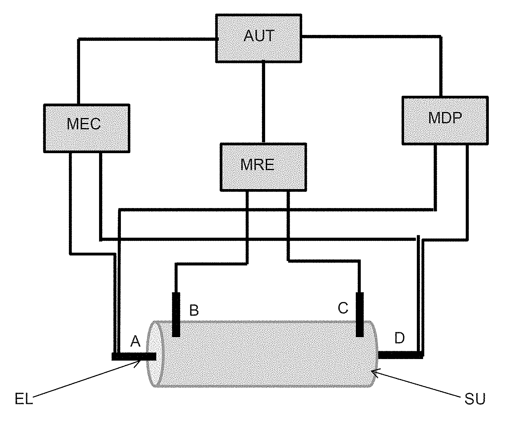
[0064] FIG. 2 presents an embodiment variant of the device according to the invention intended for laboratory measurements.
[0065] FIG. 3 presents an embodiment variant of the device according to the invention intended for well measurements.
[0066] FIG. 4 presents an example of a configuration intended for the permanent monitoring of a site for exploiting a fluid contained within a formation, comprising two devices according to the invention intended for well measurements.
[0067] FIG. 5 presents the evolution of the electric potential difference dV as a function of the variation in fluid pressure dP for various samples originating from an underground formation.
[0068] FIG. 6 presents the evolution of the relative electrokinetic coupling coefficient Cr as a function of the fluid saturation Sw, for various positions of electrodes illustrated in FIG. 2, in the case of a Brauvilliers limestone.
[0069] FIG. 7 presents the evolution of the phase angle P of the complex electrical resistivity as a function of the frequency F in the case of a Brauvilliers limestone, for various brine saturations Sw.
DETAILED DESCRIPTION OF THE DEVICE
[0070] One of the subjects of the invention relates to a device for an integrated measurement of the complex electrical resistivity and of the spontaneous potential, with a view to determining petrophysical parameters relating to a portion of an underground formation comprising a fluid. These petrophysical parameters are in particular useful for determining a plan for the optimal exploitation of the underground formation studied.
[0071] A portion of the underground formation studied may be for example: [0072] a sample of the formation, removed by core drilling for example: in this case, the device according to the invention is intended for so-called "laboratory" measurements and is referred to as "laboratory device according to the invention" hereinafter; [0073] a zone surrounding a well drilled into the formation studied and into which the device is inserted; in this case, the device according to the invention is intended for so-called "logging" measurements and is referred to as "well device according to the invention" hereinafter.
[0074] The device according to the invention comprises: [0075] at least two electrodes; [0076] a means for emitting a variable-frequency electric current, connected to at least two electrodes; [0077] a means for measuring the electrical resistivity in terms of amplitude and phase (or complex electrical resistivity measuring means), connected to at least two other electrodes; [0078] a means for measuring an electric potential difference, connected to at least two electrodes.
[0079] Thus, the device according to the invention makes it possible to perform, in an integrated manner and in a single experiment, at least two types of measurements: a spontaneous potential measurement (by means of at least two of the electrodes and of the means for measuring an electric potential difference) and a spectral induced polarization measurement (by means of at least two of the electrodes, of the means for emitting a variable-frequency electric current, and of the means for measuring the electrical resistivity in terms of amplitude and phase).
[0080] Consequently, the device according to the invention makes it possible to guarantee that two types of measurements, namely Spontaneous Potential measurements and Spectral Induced Polarization measurements, are performed under the same experimental conditions (identical portion of the formation that is not degraded by successive measurements, strictly identical positions of the electrodes for the two types of measurement, strictly identical pressure and temperature conditions, etc), which increases the reliability of the measurement.
[0081] Furthermore, having one and the same device for integrated measurements makes it possible, for a producer, to reduce the overall operating costs of the device (reduced purchase and maintenance costs with a single device, reduction in the number of handling operations by the technician in charge of the experiments).
[0082] Moreover, the combination of the Spontaneous Potential measurements and of the Spectral Induced Polarization measurements makes it possible to attain petrophysical parameters essential for the characterization of the portion of the formation studied, and thereby for the definition of a plan for the optimal exploitation of the formation studied. This point will be expanded upon more fully hereinbelow in the description of the process according to the invention.
[0083] According to one implementation of the invention, the means for measuring the electrical resistivity in terms of amplitude and phase comprises a means for measuring the electric potential difference and a means for processing the electric potential difference measurement. The means for processing the electric potential difference measurement makes it possible to determine the amplitude and the phase of the electric potential difference measurement performed for an electric current emitted at a given frequency with the means for emitting a variable-frequency electric current.
[0084] Furthermore, the device according to the invention comprises a means for automating the measurements performed by the device according to the invention, and/or a means for collecting and/or analyzing said measurements. In this way, by the automating means, the measurements to be performed by the device according to the invention may be preprogrammed and do not require human intervention in order to manually modify the measurement parameters (intensity of the current injected, frequencies sampled, etc.) and/or the measurement conditions (surrounding pressure, temperature, fluid saturation, etc.). The means for collecting the measurements further makes it possible to gather, centralize and store all of the measurements performed by the device according to the invention, automatically by the automating means, or with human intervention. Finally, the means for analyzing the measurements, performed in an automated manner or manually by a technician, collected by a collection means or manually by a technician, may be analyzed automatically and systematically by an analysis means. This analysis means may comprise a computer on which software is implemented that makes it possible to analyze the measurements resulting from the device according to the invention. For example, this software may make it possible to plot a plurality of curves, representing the values measured as a function of various measurement parameters and/or measurement conditions, which parameters and conditions have for example been preprogrammed in advance by the specialist.
[0085] According to one embodiment of the invention, the frequencies emitted by the means for emitting a variable-frequency electric current are between 1 .mu.Hz and 1 GHz. In this way, and with the aid of the means for measuring the electrical resistivity in terms of amplitude and phase according to the invention, an estimation of the spectral induced polarization (denoted SIP hereinafter) in a wide range of frequencies is attained. FIG. 1 presents an example of a result of Spectral Induced Polarization measurements, in particular their real part R and their imaginary part X, for frequencies between 1 .mu.Hz and 1 GHz, the measurements having been carried out on a given rock sample (Brauvilliers limestone of "oolitic grainstone" type), this being for various brine saturations S.sub.w (between 27% and 100%, the values increasing along the direction indicated by the arrow, a value of S.sub.w=100% corresponding to total brine saturation) and various types of brine (brine containing 10 g of NaCl and brine containing 5 g of NaCl in this case). In particular it is possible in this figure to distinguish three domains in which the SIP measurements have substantially different behaviors: the low-frequency domain (domain D1), the medium-frequency domain (domain D2), and the high-frequency domain (domain D3). Thus, in: [0086] the low-frequency domain (domain D1), i.e. for frequencies below for example 20 Hz (it should be noted that this frequency may depend on the materials), the SIP is particularly sensitive, in the case of a brine saturation of 100%, to the size of the polarizable grains, to the specific surface area, to the pore size, to the permeability, and to the cementation exponent m of Archie's law, whereas in the case of a two-phase medium (comprising water or brine, and another non-conductive fluid such as gas and/or oil, to the percentage brine saturation S.sub.w. It can be demonstrated that the SIP can be characterized in the low-frequency field by two parameters: a relaxation time (also referred to as low-frequency critical frequency) and a phase angle; [0087] the medium-frequency domain (domain D2), i.e. for frequencies between for example 20 Hz and 30 kHz, the variations of the SIP are in the form of a plateau and the SIP is sensitive in particular to the saturation of the medium, to the permeability, and to the specific surface area; [0088] the high-frequency domain (domain D3), i.e. for frequencies above for example 0.03 MHz, the variations of the SIP are again very sensitive to the frequency, which makes it possible to obtain information in particular on the relative dielectric permittivity, the saturation of the porous medium, the porosity and the cation exchange capacity.
[0089] Preferentially, the device according to the invention makes it possible to emit an electrical signal in a range of frequencies having a lower limit between 1 and 20 mHz (and preferentially equal to 10 mHz), and an upper limit between 28 and 32 MHz (and preferentially equal to 30 MHz), which makes it possible to limit the times devoted to the measurement, while making it possible to attain the aforementioned quantities. Indeed, as shown in FIG. 1, these limit values of the preferential frequency range are sufficient in order to "capture" the main trends of the variations of the complex electrical resistivity as a function of the frequency emitted, which will make it possible to deduce therefrom petrophysical parameters (such as saturation, permeability, porosity, etc.) that are characteristic of the portion of formation considered.
[0090] According to one embodiment of the invention, the Spectral Induced Polarization measurements are performed for around fifty separate frequency values regularly sampling, on a logarithmic scale, the chosen frequency range.
[0091] According to one embodiment of the invention, the electrodes of the device according to the invention consist of a conductive material (such as metal) that is nonpolarizable (for example composed of silver or silver chloride). This embodiment makes it possible to perform successive electrical measurements, without having to wait for the electrodes to return to a neutral electrical state. A time saving over all of the experiments to be performed, for a series of frequencies within a given range and according to a given sampling interval, is thus obtained.
[0092] According to one embodiment of the invention, the device comprises between four and eight electrodes, preferably six. The plurality of electrodes makes it possible to perform electric potential difference measurements and/or electrical resistivity measurements at various locations of the portion of formation studied and also to better characterize the portion of formation.
[0093] Preferentially, the device further comprises a support, formed of an insulating material, at least a number of the electrodes being distributed over a length of the support in question. The dimensions and the shape of the support are a function of the dimensions and the shape of the portion of the formation considered, so that the number of the electrodes of the device distributed over a length of the support are in contact with the portion of the formation studied.
[0094] According to one embodiment of the invention, in which the portion of the formation studied is a sample of the formation, removed by core drilling for example, the support may be a flexible sleeve, along which a number of the electrodes are distributed, the dimensions of the support enabling the electrodes in question to be in contact with the sample studied when the latter is inserted in the sleeve. A sample removed from an underground formation generally being of substantially cylindrical shape, the sleeve is preferably also of substantially cylindrical shape; the circumference thereof may be slightly greater than that of the sample, so that the sample can be inserted into the sleeve at the same time as being held.
[0095] According to one embodiment of the invention in which the portion of the formation is a zone surrounding a well drilled in the formation studied, the support is of substantially cylindrical shape (a well having a very generally cylindrical shape). The electrodes are distributed along the axis of revolution of the support, and the circumference of the support is related to the circumference of said well so that the support can be inserted into the well and so that the electrodes are in contact with the portion of the formation to be studied. Advantageously, the electrodes are rings with a diameter slightly greater than the diameter of the support and are fastened to said support. Current receiving and emission is then possible radially in the formation studied.
First Embodiment: Device for Laboratory Measurements
[0096] According to one embodiment of the invention in which the device according to the invention is intended for laboratory measurements on a sample of the formation studied (referred to as the first embodiment of the invention hereinafter or else device for laboratory measurements according to the invention), two electrodes are evenly positioned along the axis of revolution of the sleeve and two other electrodes are free and could be placed so as to establish an electrical contact on each of the free cross sections of the sample of formation inserted in the sleeve. The electrodes placed on the free cross sections are connected to the means for emitting the variable-frequency electric current, and the at least two other electrodes distributed on the sleeve are connected to the means for measuring the electrical resistivity in terms of amplitude and phase. Advantageously, the set of the electrodes is also connected to the means for measuring the electric potential difference, for example via a multiplexer.
[0097] In a variant of this first main embodiment of the invention, the sleeve in question may comprise a heat-shrinkable sheath. This type of sheath withstands in particular high temperatures and high pressures while preserving the leaktightness of the sheath. This type of sheath is furthermore inert from the physicochemical point of view. Advantageously, two electrodes are pierced through the sheath (so as to pass through this sheath) and to thus enable contact with the sample inserted into the sheath. These electrodes are electrically connected to the means for measuring the complex electrical resistivity, and preferentially also to the means for measuring the electric potential. At least two other electrodes are in direct contact with the sample and are electrically connected to the means for emitting a variable-frequency electric current, and preferably also to the means for measuring the electric potential.
[0098] In another variant of this first main embodiment of the invention, the device further comprises means for injecting a working fluid into the sample and for regulating the flow rate of said working fluid.
[0099] The means for injecting a working fluid into said sample and for regulating the flow rate of said working fluid may make it possible to perform complex electrical resistivity measurements and spontaneous potential measurements for various types of fluid (water, oil, gas in particular) and for various respective saturation values of these fluids. This makes it possible to evaluate petrophysical parameters relating to a sample of an underground formation for various fluid saturation conditions (various fluids and for various saturations). These various measurements may in particular make it possible to plot nomograms for informing the specialist of the petrophysical parameters expected for the formation considered, as a function of the various possible saturation conditions.
[0100] A means of measuring the fluid pressure in at least two locations of the sample will advantageously be combined with means for injecting a working fluid into the sample and for regulating the flow rate of said working fluid. This measurement configuration makes it possible in particular to perform measurements of the electrokinetic coupling coefficient in a saturated medium.
[0101] Advantageously, the first main embodiment of the invention may further comprise a hydraulic containment cell, intended to receive a sample. The containment cell may make it possible to subject the sample of the formation considered to high pressures (for example of the order of 5 MPa). This makes it possible to simulate, within the context of a laboratory measurement, the existing pressure conditions in the underground formation, which may be of the order of 8 to 40 MPa. The spontaneous potential and electrical resistivity measurements performed under conditions that approach the conditions in situ (i.e. under the pressure conditions of the fluid reservoir studied), the petrophysical parameters that can be deduced from these measurements are representative of the actual petrophysical parameters, in situ, unlike measurements which are carried out under surface conditions (pressure of around 1 MPa).
[0102] Advantageously, the first main embodiment of the invention may further comprise a means for regulating the temperature, within said containment cell, so as to simulate the temperature conditions within the formation studied (and which may reach 60.degree. C. to 150.degree. C.).
[0103] Moreover, the first main embodiment of the invention may comprise geochemical measuring means such as means for measuring the alkalinity, conductivity, contents of major cations-anions, contents of trace elements and also the content of dissolved gas after sampling.
[0104] The specialist in the field of petroleum geochemistry has perfect knowledge of means for carrying out such measurements. These measurements make it possible to give the specialist information regarding the precise characteristics of the fluids and gases involved, which may help to refine the optimal exploitation plan targeted by the present invention.
[0105] FIG. 2 presents a variant of the first main embodiment of the device according to the invention, the various elements of the device in question possibly being arranged differently. Thus, this figure describes a device comprising a support SU of cylindrical shape, 4 electrodes EL including two electrodes distributed along the support SU and two other free electrodes EL, intended to be placed on each of the free cross sections of the sample of formation inserted in the support SU. The electrodes EL to be placed on the free cross sections are connected to the variable-frequency electric current emitting means MEC, and the two other electrodes EL distributed on the sleeve SU are connected to the means MRE for measuring the electrical resistivity in terms of amplitude and phase. According to this nonlimiting exemplary embodiment of the invention, only two of the four electrodes A, D are connected to the electric potential difference measuring means MDP, enabling measurements of spontaneous potential difference only between the electrodes A and D, but connections could be made between each of the electrodes A, B, C, D and the electric potential difference measuring means MDP in order to enable a measurement of potential difference between the electrodes A and B, A and C and A and D for example. Furthermore, in this exemplary embodiment, the variable-frequency electric current emitting means MEC, the means MRE for measuring the electrical resistivity in terms of amplitude and phase, and the electric potential difference measuring means MDP are connected to an automaton AUT enabling the measurements to be performed by the device according to the invention to be preprogrammed, thus making it possible to avoid any human intervention in order to manually modify the measurement parameters (intensity of the current injected, frequencies sampled, etc.).
Second Main Embodiment: Device for Logging Measurements
[0106] According to one embodiment of the invention in which the device according to the invention is intended for measurements within at least one well drilled in the formation studied such as logging measurements (referred to as the second main embodiment of the device according to the invention, or else device for well measurements hereinafter), the complex resistivity measuring means, the electric potential difference measuring means, and the electric current emitting means are intended to be placed at the surface of said formation and are connected to said electrodes by connection means that are resistant to the pressure and temperature conditions inherent to measurements in wells.
[0107] This main embodiment of the device according to the invention makes it possible to perform, with a single logging tool, two types of measurement (electrical in this case), which is very advantageous from an operational point of view since the implementation of logging measurements is well known for being highly technical and expensive. Furthermore, it is ensured in this way that the two measurements are perfectly performed at the same depth in the well and are representative of the same portion.
[0108] According to one embodiment of this second main embodiment of the invention, the electrodes are placed in direct contact with the wall of the well and therefore with the geological formation. According to one embodiment of this second main embodiment of the invention, the dimensions of the device for well measurements are of the order of 2500 mm long and 45 mm in diameter. Advantageously, the electrodes are uniformly distributed over a length of the support of 2100 mm, the distance between two consecutive electrodes being 30 mm.
[0109] FIG. 3 presents a variant of the second main embodiment of the device according to the invention, for well measurements, the various elements of the device in question possibly being arranged differently. In the example presented, the support SU is a cylindrical tube placed in a well W drilled in a formation F, along which 7 annular electrodes EL are distributed, each electrode being connected to the spontaneous potential measuring means MDP and to the complex electrical resistivity measuring means MRE, the electrodes that are at the two ends of the support being furthermore connected to the variable-frequency electric current emitting means MEC. Furthermore, the complex electrical resistivity measuring means MRE, the spontaneous potential measuring means MDP and the variable-frequency electric current emitting means MEC are placed at the surface.
[0110] Process for Exploiting an Underground Formation:
[0111] Moreover, the invention relates to a process for exploiting an underground formation comprising a fluid. This process requires at least one sample removed from the formation studied, the formation being passed through by at least one well, and comprises at least the following steps: [0112] Step 1: for at least one measurement condition, measurements of spontaneous potential and of spectral induced polarization are performed on the sample considered by means of an embodiment of the device for laboratory measurements comprising means for injecting a working fluid into the sample, means for regulating the flow rate of the working fluid, and also a means for measuring the fluid pressure in at least two locations of said sample, and petrophysical parameters representative of said sample are determined; [0113] Step 2: measurements of spontaneous potential and of spectral induced polarization are performed in the well considered by means of at least one device according to any one of the variants of the second main embodiment of the device according to the invention (i.e. the embodiment intended for well measurements); [0114] Step 3: the values of the measurements performed in the well are compared with the measurements performed on said sample, and by calibration, petrophysical parameters representative of said formation are deduced; [0115] Step 4: using said parameters representative of said formation, a plan for optimal exploitation of the fluid of the formation studied is defined and the fluid of the formation is exploited using said plan.
[0116] Thus, the process according to the invention comprises the implementation of measurements of different types (SP and SIP at least) and on different scales (well scale and laboratory scale). The various steps of the process according to the invention will be described in detail below.
[0117] Step 1
[0118] During this step, the process according to the invention is carried out by means of a variant of the first main embodiment of the device according to the invention, comprising means for injecting a working fluid into said sample and for regulating the flow rate of said working fluid, and also a means for measuring the fluid pressure in at least two locations of said sample.
[0119] The measurements carried out with the aid of this device (referred to as "laboratory measurements" hereinafter) are performed for at least one measurement condition. The expression "measurement condition" is understood to mean the set of the parameters according to which the measurement is carried out, such as for example the pressure, the temperature, the fluid(s) present in the sample, or the saturation of each the fluid present in the sample. Very preferentially, the laboratory measurements are carried out under measurement conditions representative of the conditions (of pressure, of temperature, of saturations of the fluids involved) to which the formation studied is subjected, that will be referred to as "in situ conditions" hereinafter. It should be noted that the in situ conditions are not generally precisely known but the specialist may deal with orders of magnitude or ranges of the in situ conditions (ranges relating to the pressures and/or temperatures and/or saturations of the fluids involved). The laboratory measurements are advantageously performed for a plurality of measurement conditions, in particular sampling the ranges of the presumed values of the in situ conditions.
[0120] From said laboratory measurements, petrophysical parameters relating to the sample considered are determined for the measurement condition(s) considered (pressure and/or temperature and/or fluid saturation conditions). The specialist has perfect knowledge of methods for determining petrophysical parameters from SIP and SP measurements. According to one embodiment of the invention, the petrophysical parameters representative of the sample are the relative permeability and/or the fluid saturation. When measurements were performed for a plurality of measurement conditions, the specialist may draw up a nomogram representing the values of the measurements performed, the petrophysical parameters deduced from these measurements, and this being for each measurement condition.
[0121] According to one embodiment of the process according to the invention, for at least one predefined containment pressure, one temperature, one predefined fluid saturation, one predefined fluid flow rate, and one injection of given working fluid into said sample: [0122] a. the pressure gradient induced in the sample is measured by means of the fluid pressure measuring means; [0123] b. the electric potential difference induced in the sample is measured by means of the electric potential difference measuring means; [0124] c. the spectral induced polarization within said sample is measured by means of the spectral induced polarization measuring means; and the measurements a), b) and c) are repeated for various fluid flow rates and/or for various fluid saturations and/or for various working fluids. Nonlimiting methods for exploiting the measurements thus performed in order to determine the relative permeability and the fluid saturation are given below.
Determination of Petrophysical Parameters
[0125] The spontaneous potential measurements make it possible to measure an electric potential difference (that will be denoted dV hereinafter). Combined with the pressure gradient measurements (that will be denoted dP hereinafter), an electrokinetic coupling coefficient C is obtained according to a formula of the type:
C=dV/dP,
[0126] According to the embodiment described above, since the measurements are carried out for various fluid saturation conditions, it is possible to define an electrokinetic coupling coefficient in a saturated medium Csat and an electrokinetic coupling coefficient in an unsaturated medium C(Sw.ltoreq.1). A relative electrokinetic coupling coefficient Cr is then defined, corresponding to the ratio between the electrokinetic coefficient in a saturated medium Csat and the electrokinetic coefficient in an unsaturated medium C(Sw.ltoreq.1). It is also possible to estimate an electroosmosis coefficient Celectro which quantifies the variation in fluid pressure induced by an electric potential difference.
[0127] Furthermore, the SIP measurements performed according to the embodiment described above make it possible to measure the complex resistivity, in a saturated medium and in an unsaturated medium. From these measurements, it is possible to deduce for example the following parameters: [0128] a phase angle .THETA., from a formula of the type: tan .THETA.=X/R, where R is the real part of the resistivity and X is the imaginary part; [0129] a relaxation time .tau., a critical frequency Fc; [0130] a resistivity index
[0130] I R = R t R o , ##EQU00001##
where R.sub.t and R.sub.0 are respectively the real part of the resistivity in an unsaturated medium and in a saturated medium; [0131] a formation factor
[0131] F = R 0 R w , ##EQU00002##
where R.sub.0 is the resistivity of the medium 100% saturated with brine, R.sub.w is the resistivity of the brine R. From the phase angle .THETA., the formation factor F, the relaxation time .tau., and the critical frequency Fc, a specialist can deduce therefrom the fluid saturation Sw. A specialist is in particular familiar with the formula:
.tau. = ( 4 KF D ( + ) s ) S w 2 ##EQU00003##
which makes it possible to deduce the saturation S.sub.w from the formation factor F, the permeability K (which may be known moreover, from petrophysical laboratory measurements, such measurements being well known to a specialist), D.sub.(+).sup.S is the diffusion coefficient (which may be known moreover, from petrophysical laboratory measurements, such measurements being well known to a specialist or else determined by a formula).
[0132] Then, from the fluid saturation S.sub.w and knowing moreover that the resistivity index can also be written I.sub.R=S.sub.w.sup.-n, n is deduced therefrom, which is the saturation exponent of Archie's law.
[0133] The relative permeability can then be obtained according to a formula of the type:
K.sub.r=C.sub.rS.sub.w.sup.n+1
[0134] Advantageously, the measurements described above can in addition be repeated for various containment pressures and/or various temperatures. In order to do this, the device according to the first main embodiment of the device according to the invention may comprise a hydraulic containment cell and/or temperature-regulating means. Thus, the invention makes it possible to perform laboratory measurements for various measurement conditions (of pressure, of temperature, of fluid, of respective saturation of the fluids). In this way, a specialist can for example establish a nomogram of the petrophysical parameters determined as a function of these measurement conditions.
[0135] Step 2
[0136] According to the process according to the invention, measurements of spontaneous potential and of spectral induced polarization are additionally performed in the well considered by means of the device according to any one of the variants of the second main embodiment of the device according to the invention. These measurements will be referred to as "well measurements" hereinafter.
[0137] By comparing the values of the measurements performed in the well with those performed in the laboratory, the petrophysical parameters of the formation studied are determined as a function of the petrophysical parameters obtained by the laboratory measurements. This determination may assume various forms: a direct attribution of the parameters obtained by laboratory measurements (in particular if there is perfect correspondence between laboratory measurements and logging measurements), or else by interpolation of several parameters, by extrapolation, or else by application of any ad hoc function. According to one embodiment of the invention, a scaling function of the measurements performed in the laboratory relative to the measurements performed in the well is applied, so as to take into account different scale factors between these two types of measurement.
[0138] According to one embodiment of the invention, a scaling of the measurements performed in laboratory relative to the measurements performed in the well is applied first, in order to take into account the different measurement conditions.
[0139] An example of an embodiment variant of the process according to the invention is presented in FIG. 4. Thus, this variant comprises two well measurement devices, one placed in an injection well WI and one placed in a producing well WP for producing the fluid contained in the formation studied, the two wells being spaced around a hundred meters apart. For example, when the fluid injected is CO.sub.2, such a configuration may make it possible to investigate the variations in petrophysical parameters between the two wells and thus to monitor the CO.sub.2 front (via the saturation) between the wells.
[0140] Step 3
[0141] From the petrophysical parameters thus determined for the formation studied, it is possible to define a plan for optimal exploitation of the fluid contained in the formation studied, i.e. an exploitation plan that enables optimal exploitation of a fluid considered according to technical-economic criteria predefined by a specialist. It may be a scenario that offers a high degree of recovery of the fluid, over a long exploitation time, and that requires a limited number of wells. According to one embodiment of the invention, the optimal exploitation plan may be defined by determining a fluid recovery process (primary, secondary or tertiary recovery process), and also a number, a positioning and a geometry of injection and/or producing wells that make it possible to satisfy predefined technical-economic criteria. Various scenarios may be envisaged and the respective profitability thereof may be approached with the aid of a reservoir simulation. The scenario offering the highest predicted profitability could for example be used.
[0142] Step 4
[0143] Next, according to the invention, the fluid from the formation studied is exploited as a function of the exploitation plan determined in step 3, that best satisfies the technical-economic criteria predefined by a specialist.
[0144] The exploitation of the fluid from the formation studied may then consist of the creation of boreholes according to the number and the positioning determined in step 3, some of these wells being intended to be injection wells and others producing wells, for injecting into the injection wells possible fluids that aim to improve the recovery of the fluids in place.
[0145] According to one embodiment of the invention in which the well measurements described in step 2 are repeated at various moments of the exploitation of the fluid from the formation studied, the laboratory measurements having been performed first for various measurement conditions, the petrophysical parameters such as the relative permeability and the fluid saturation will be able to be monitored in real time, throughout the production of the fluid. The exploitation plan determined in step 3 could then be revised throughout the exploitation of the fluid from the formation, and the recovery of fluid in step 4 improved.
Exemplary Embodiment
[0146] The features and advantages of the process according to the invention will become more clearly apparent on reading the exemplary embodiment below.
[0147] The exemplary embodiment in question was carried out with a device according to the first main embodiment of the invention (laboratory device) comprising the following elements:
Containment Equipment
[0148] A Coreflood containment cell (Vinci Technologies, France): this is an adjustable piston containment cell, with three inlets on an injection coil, three outlets on an outlet coil, and which is transparent to x-rays. Such a cell may make it possible to perform measurements up to a hydraulic containment pressure of 50 bar of Marcol. The latter ensures the electrical insulation of the contacts. [0149] A Viton heat-shrinkable sheath (Hellermann-Tyton, France) equipped with 12 piercings distributed along the generatrix of the sheath and enabling the electrical contacts to be introduced (2 diametrically opposed piercings per electrical measuring point).
Measuring and Regulating (P, T, Flow Rate) Equipment
[0149] [0150] A 260 D ISCO pump, equipped with an offset pressure sensor, regulates the hydraulic pressure of the containment up to 50 bar as closely as possible to the cell and absorbs the pressure fluctuations linked to the temperature. [0151] An Amersham/Bioscience P920 liquid injection pump covers a flow rate range from 0.00 to 20.00 ml/min, and is used for injecting brine into the porous medium. [0152] A Pharmacia P500 liquid injection pump having a range 1-499 ml/h is used for making up the volume of the system following samplings and the recirculation of the brine on the back face of the porous medium, in order to maintain the capillary contact and the zero capillary pressure at the outlet. [0153] A system of 3 outlet valves makes it possible to purge the dead volumes of the cell of brine and to improve the determination of the pore volume. [0154] Two Keller PAA-33X (0-30 bar) pressure sensors measure the relative pressure upstream and downstream of the assembly. They also enable the control of the injection pressure at the top of the porous medium and the adjustment of the pore pressure. Furthermore, the downstream sensor makes it possible to balance the pressure of the sampling loop with the pore pressure following a sampling, so as not to destabilize the pore pressure of the system. [0155] A Keller PD39X pressure sensor measures the differential pressure generated by the flow in the porous medium. [0156] A Bronhkorst P702CV gas pressure regulator (Bronhkorst, France) makes it possible to control the pore pressure up to 20 bar, by regulating the pressure of the gas fraction contained in the separator. [0157] A Bronhkorst F-201-CV gas flow regulator (Bronhkorst, France), calibrated with N.sub.2 and CO.sub.2, covers a range of flow rates that are normalized in terms of pressure and temperature (P.sub.atm, and 0.degree. C.) from 1 to 310 mln/min. It is used to inject the gas at the inlet of the porous medium and makes it possible to regulate the flow rate up to a pressure of 20 bar. [0158] A PT100 temperature probe measures the temperature of the brine entering the porous medium. It makes it possible to correct the viscosity of the brine, the density and the resistances measured by the Arps equation. [0159] A two-phase brine/gas separator: placed downstream of the cell, it makes it possible to reinject the collected brine that has already passed through the porous medium. It also makes it possible to measure the volume variations resulting from the porous medium during the experiment Kr.
Electrical Resistivity and Spontaneous Potential Measurement Equipment
[0159] [0160] A Solartron Si1260: this is an impedance/Gain-Phase analyser, enabling measurements of resistance and phase shift (R, X) with a frequency sweep over a range from 1 mHz to 32 MHz, by adjustable intervals. The measurements are performed with the generator set at 1 volt ac. Coupling with the Agilent multiplexor makes it possible to work with 2 or 4 electrodes. [0161] The Solartron also makes it possible to inject a direct voltage of from 0 to .+-.40 volt in order to calculate the electroosmosis coefficient of the system. [0162] An Agilent 34970A acquisition system equipped with a multiplexing board enables the acquisition of potentials between the selected sections of the porous medium. [0163] A central acquisition unit recovers all of the measurements performed on a PC, via the
[0164] Labview acquisition system. [0165] 4 nonpolarizable electrodes positioned as presented in FIG. 2.
Experimental Protocol
Sample Preparation and Characteristics
[0166] The porous medium is derived from a block from a referenced quarry. It is cored with a diameter of 40 mm and sawn with a parallel-sided saw, in water. The samples are dried in an oven at 60.degree. C. The sample is weighed when dry. The geometrical characteristics of the experimental sample are determined using vernier calipers: diameter and length. The sample is photographed and referenced.
Installing the Sample in the Cell
[0167] The sample is mounted in the Viton sheath, the electrodes are connected and the contacts are verified using a multimeter. The sample and its sheath are mounted in the cell and placed under hydraulic containment with Marcol, at the chosen containment pressure (30 bar). The containment pressure is at least 15 bar higher relative to the pore pressure chosen for the experiment.
[0168] The sample is then placed under rough vacuum. A brine of chosen concentration is produced (here 10 g/l of NaCl), and its conductivity is measured. The sample is saturated with the brine, at the pore pressure chosen for the experiment, with the aid of a pressure-regulating Isco pump.
Measurements Performed
[0169] The following measurements are performed: [0170] 1--Successive measurements of spontaneous potential at each section of the sample, coupled with the variations of dP (induced by a flow rate variation) until the system is at a pseudo-equilibrium (i.e. until the spontaneous potentials SP stabilize). This measurement makes it possible to determine the electrokinetic coupling coefficient. [0171] 2--Spectral induced polarization measurements with a frequency sweep, at 100% brine saturation and under the experimental flow rate, with 4 electrodes (2 injection electrodes and 2 measuring electrodes), at 1 volt, over the range extending from 1 mHz to 30 MHz. This measurement enables the measurement of the resistivity index (IR) when the measurement is repeated at various degrees of saturation. [0172] 3--Spectral induced polarization measurements with a frequency sweep, at 100% brine saturation and under the experimental flow rate, with 4 electrodes, at 1 volt, over the range extending from 1 mHz to 30 MHz. The objective of this operation is to obtain a phase angle (phase shift between the "R" values and the "X" values), a relaxation time and also a critical frequency for each section analyzed. [0173] 4--Measurements of pressure gradients, at the inlet and outlet of the sample; [0174] 5--Measurements of induced potentials, in a range extending from 0 to .+-.40 volt, are carried out over the whole of the porous medium and give rise to variations of dP. This type of measurement makes it possible to determine the electroosmosis coefficient.
[0175] The first 4 steps above were carried out for various fluid saturations (draining/soaking steps).
[0176] The set of measurements performed according to the experimental protocol defined below make it possible to plot curves of variations of the measurements performed as a function of the measurement conditions. Examples of such curves, also referred to as nonograms, are presented in FIGS. 5 to 7.
[0177] Thus, FIG. 5 presents the curves of variations of the electric potential difference dV as a function of the variation of fluid pressure dP for samples of Brauvilliers limestone (white circles), Saint-Emilion limestone (black squares), and dolomites LS2 (crosses). From the slopes of these curves, the electrokinetic coupling coefficient is respectively deduced (in a saturated medium in the present case), for each of the samples considered.
[0178] FIG. 6 presents the evolution of the relative electrokinetic coupling coefficient Cr as a function of the fluid saturation Sw, in the case of the Brauvilliers limestone, and for various positions of the electrodes, the positions of the electrodes ABCD being presented in FIG. 2.
[0179] FIG. 7 presents the evolution of the phase angle P of the complex electrical resistivity as a function of the frequency F in the case of the Brauvilliers limestone, and for various brine saturations Sw (between 27% and 100%, the increase in the saturation values being shown by an arrow in FIG. 7). As indicated in FIG. 7, it is possible to deduce therefrom, for each saturation condition Sw, a value of the phase angle .THETA. (ordinate of the first peak formed by the curve), a relaxation time .tau. (abscissa of the first peak formed by the measurement curve) and a critical frequency Fc (abscissa of the first trough formed by the measurement curve).
[0180] Thus such curves, obtained in particular by both SP and SIP measurements, for various samples representative of the formation studied and for various measurement conditions, form nonograms, which enable a specialist, having in addition at his/her disposal, according to the process according to the invention, electrical measurements of the same type (i.e. of SP and SIP type) performed in the well, to make connections between the values of the well measurements and the values of the laboratory measurements, and to deduce therefrom the in situ petrophysical parameters, such as the relative permeability and the fluid saturation. These petrophysical parameters are particularly useful to a specialist for defining a plan for the optimal exploitation of the formation studied.
* * * * *
D00000
D00001
D00002
D00003
D00004
XML
uspto.report is an independent third-party trademark research tool that is not affiliated, endorsed, or sponsored by the United States Patent and Trademark Office (USPTO) or any other governmental organization. The information provided by uspto.report is based on publicly available data at the time of writing and is intended for informational purposes only.
While we strive to provide accurate and up-to-date information, we do not guarantee the accuracy, completeness, reliability, or suitability of the information displayed on this site. The use of this site is at your own risk. Any reliance you place on such information is therefore strictly at your own risk.
All official trademark data, including owner information, should be verified by visiting the official USPTO website at www.uspto.gov. This site is not intended to replace professional legal advice and should not be used as a substitute for consulting with a legal professional who is knowledgeable about trademark law.