Mounting Structure, Rotational Machinery, Air Conditioning Apparatus, And Adjustment Method
SAKAI; Misuzu ; et al.
U.S. patent application number 16/123647 was filed with the patent office on 2019-03-21 for mounting structure, rotational machinery, air conditioning apparatus, and adjustment method. This patent application is currently assigned to Kabushiki Kaisha Toshiba. The applicant listed for this patent is Kabushiki Kaisha Toshiba. Invention is credited to Takayuki MASUNAGA, Shanying PAN, Misuzu SAKAI.
| Application Number | 20190085860 16/123647 |
| Document ID | / |
| Family ID | 65720054 |
| Filed Date | 2019-03-21 |

View All Diagrams
| United States Patent Application | 20190085860 |
| Kind Code | A1 |
| SAKAI; Misuzu ; et al. | March 21, 2019 |
MOUNTING STRUCTURE, ROTATIONAL MACHINERY, AIR CONDITIONING APPARATUS, AND ADJUSTMENT METHOD
Abstract
According to one embodiment, a mounting structure includes: a first member including a first outer surface provided with first dents arranged around a second axis at an interval of a first angular distance; a second member including a second inner surface provided with second dents arranged around the second axis at an interval of a second angular distance, and a second outer surface provided with third dents arranged around a third axis at an interval of a third angular distance; a third member includes a third inner surface provided with fourth dents arranged around the third axis at an interval of a fourth angular distance; a first limiting member housed in one of the first dents and one of the second dents opposing each other; and a second limiting member housed in one of the third dents and one of the fourth dents opposing each other.
| Inventors: | SAKAI; Misuzu; (Yokohama, JP) ; MASUNAGA; Takayuki; (Yokohama, JP) ; PAN; Shanying; (Chigasaki, JP) | ||||||||||
| Applicant: |
|
||||||||||
|---|---|---|---|---|---|---|---|---|---|---|---|
| Assignee: | Kabushiki Kaisha Toshiba Minato-ku JP |
||||||||||
| Family ID: | 65720054 | ||||||||||
| Appl. No.: | 16/123647 | ||||||||||
| Filed: | September 6, 2018 |
| Current U.S. Class: | 1/1 |
| Current CPC Class: | F04D 29/662 20130101; F04D 29/281 20130101; F04D 29/263 20130101; F04D 29/668 20130101; F04D 25/08 20130101 |
| International Class: | F04D 29/26 20060101 F04D029/26; F04D 29/28 20060101 F04D029/28; F04D 29/66 20060101 F04D029/66 |
Foreign Application Data
| Date | Code | Application Number |
|---|---|---|
| Sep 15, 2017 | JP | 2017-178343 |
Claims
1. A mounting structure, comprising: a first member including: a first inner surface that extends along and around a first axis, at least a part of the first inner surface which forms a first hole; and a first outer surface that is opposite the first inner surface, extends along and around a second axis different from the first axis, and is provided with one or more first dents arranged around the second axis at an interval of a first angular distance; a second member including: a second inner surface that extends along and around the second axis and is provided with one or more second dents arranged around the second axis at an interval of a second angular distance different from the first angular distance, at least a part of the second inner surface which forms a second hole that allows the first member to be housed, in contact with the first outer surface of the first member; and a second outer surface that is opposite the second inner surface, extends along and around a third axis different from the second axis, and is provided with one or more third dents arranged around the third axis at an interval of a third angular distance; a third member including: a third inner surface that extends along and around the third axis and is provided with one or more fourth dents arranged around the third axis at an interval of a fourth angular distance different from the third angular distance, at least a part of the third inner surface which forms a third hole that allows the second member to be housed, in contact with the second outer surface of the second member; a first limiting member that is housed in one of the one or more first dents and one of the one or more second dents opposing each other, and limits rotation of the first member and the second member around the second axis; and a second limiting member that is housed in one of the one or more third dents and one of the one or more fourth dents opposing each other, and limits rotation of the second member and the third member around the third axis.
2. The mounting structure according to claim 1, wherein the first axis, the second axis, and the third axis are in parallel with one another, and a distance between the first axis and the second axis is equal to a distance between the second axis and the third axis.
3. The mounting structure according to claim 2, wherein a first difference between the third angular distance and the fourth angular distance is a divisor of at least one of the third angular distance and the fourth angular distance.
4. The mounting structure according to claim 3, wherein at least one of the third angular distance and the fourth angular distance is set to a divisor of 360-degree angle.
5. The mounting structure according to claim 4, wherein a first angle .theta..sub.1 being one of the third angular distance and the fourth angular distance is equally divided into n.sub.1 parts by a difference .DELTA..theta..sub.12 between the first angle .theta..sub.1 and a second angle .theta..sub.2 being the other of the third angular distance and the fourth angular distance, a 360-degree angle is equally divided into n.sub.2 parts by the first angle .theta..sub.1, when the difference .DELTA..theta..sub.12 is a divisor of 360-degree angle, a combination of the first angle .theta..sub.1 and the second angle .theta..sub.2 satisfies the following first expression: ( n 1 - 1 ) 2 n 1 - n 2 < 0 ( if .theta. 1 > .theta. 2 ) n 1 2 - 1 n 1 - n 2 < 0 ( if .theta. 1 < .theta. 2 ) First expression ##EQU00004## and the combination results in a value closest to zero from the first expression among multiple combinations of the first angle .theta..sub.1 and the second angle .theta..sub.2, and when the difference .DELTA..theta..sub.12 differs from a divisor of 360-degree angle, the combination of the first angle .theta..sub.1 and the second angle .theta..sub.2 satisfies the following second expression: (.theta..sub.1-.DELTA..theta..sub.12).sup.2-180.degree..DELTA..theta..sub- .12<0 (if .theta..sub.1>.theta..sub.2) .theta..sub.1.sup.2-.DELTA..theta..sub.12.sup.2-180.degree..DELTA..theta.- .sub.12<0 (if .theta..sub.1<.theta..sub.2) Second expression and the combination results in a value closest to zero from the second expression among multiple combinations of the first angle .theta..sub.1 and the second angle .theta..sub.2.
6. The mounting structure according to claim 2, wherein a second difference between the first angular distance and the second angular distance is a divisor of at least one of the first angular distance and the second angular distance.
7. The mounting structure according to claim 6, wherein at least one of the first angular distance and the second angular distance is set to a divisor of 360-degree angle.
8. The mounting structure according to claim 7, wherein a third angle .theta..sub.3 being one of the first angular distance and the second angular distance is equally divided into n.sub.3 parts by a difference .DELTA..theta..sub.34 between the third angle .theta..sub.3 and a fourth angle .theta..sub.4 being the other of the first angular distance and the second angular distance, a 360-degree angle is equally divided into 1/2n.sub.4 parts by the third angle .theta..sub.3, when the difference .DELTA..theta..sub.34 is a divisor of 360-degree angle and the number of the one or more first dents or the one or more second dents arranged around the second axis at an interval of the fourth angle .theta..sub.4 is N, a combination of the third angle .theta..sub.3 and the fourth angle .theta..sub.4 satisfies the following third and fourth expressions: ( n 3 - 1 ) 2 n 3 - 2 n 4 < 0 ( if .theta. 3 > .theta. 4 ) n 3 2 - 1 n 3 - 2 n 4 < 0 ( if .theta. 3 < .theta. 4 ) Third expression 180 .degree. .DELTA. .theta. 34 .ltoreq. n 4 ( N - 1 ) ( if .theta. 4 is not a divisor of 720 ) 180 .degree. .DELTA. .theta. 34 .ltoreq. n 4 N ( if .theta. 4 is a divisor of 720 ) Fourth expression ##EQU00005## and the combination results in a value closest to zero from the third expression among multiple combinations of the third angle .theta..sub.3 and the fourth angle .theta..sub.4, and when the difference .DELTA..theta..sub.34 differs from a divisor of 360-degree angle, the combination of the third angle .theta..sub.3 and the fourth angle .theta..sub.4 satisfies the following fifth expression: (.theta..sub.3-.DELTA..theta..sub.34).sup.2-180.degree..DELTA..theta..sub- .34<0 (if .theta..sub.3>.theta..sub.4) .theta..sub.3.sup.2-.DELTA..theta..sub.34.sup.2-180.degree..DELTA..theta.- .sub.34<0 (if .theta..sub.3<.theta..sub.4) Fifth expression and the combination results in a value closest to zero from the fifth expression among multiple combinations of the third angle .theta..sub.3 and the fourth angle .theta..sub.4.
9. The mounting structure according to claim 7, wherein a difference .DELTA..theta..sub.34 between the third angle .theta..sub.3 being one of the first angular distance and the second angular distance and the fourth angle .theta..sub.4 being the other of the first angular distance and the second angular distance is a divisor of the third angle .theta..sub.3, the third angle .theta..sub.3 is a divisor of 360-degree angle, the difference .DELTA..theta..sub.4 is a divisor of 360-degree angle, and when a value obtained by dividing a 360-degree angle by the difference .DELTA..theta..sub.34 is an odd number, the third angle .theta..sub.3 and the difference .DELTA..theta..sub.34 satisfy the following sixth expression: .theta..sub.3=2.DELTA..theta..sub.34 Sixth expression and the number of the one or more first dents or the one or more second dents arranged at an interval of the fourth angle .theta..sub.4 is one.
10. Rotational machinery, comprising: the mounting structure according to claim 1; and a power source that includes a shaft to be inserted into the first hole, to rotate the shaft.
11. An air conditioning apparatus, comprising: the mounting structure according to claim 1; a power source that includes a shaft to be inserted into the first hole, to rotate the shaft; and a fan connected to the third member.
12. An adjustment method of a mounting structure that comprises: a first member including: a first inner surface that extends along and around a first axis, at least a part of the first inner surface which forms a first hole; and a first outer surface that is opposite the first inner surface, extends along and around a second axis different from and in parallel with the first axis, and is provided with one or more first dents arranged around the second axis at an interval of a first angular distance; a second member including: a second inner surface that extends along and around the second axis and is provided with one or more second dents arranged around the second axis at an interval of a second angular distance different from the first angular distance, at least a part of the second inner surface which forms a second hole that allows the first member to be housed, in contact with the first outer surface of the first member housed in the second hole; and a second outer surface that is opposite the second inner surface, extends along and around a third axis different from and in parallel with the second axis, and is provided with one or more third dents arranged around the third axis at an interval of a third angular distance; and a third member including a third inner surface that extends along and around the third axis and is provided with one or more fourth dents arranged around the third axis at an interval of a fourth angular distance different from the third angular distance, at least a part of the third inner surface which forms a third hole that allows the second member to be housed, in contact with the second outer surface of the second member housed in the third hole, a first distance between the first axis and the second axis being equal to a second distance r between the second axis and the third axis, the adjustment method comprising: rotating the first member around the second axis with respect to the second member by an angle .theta..sub.r1 from a position where the first axis and the third axis coincide with each other, in accordance with an eccentric distance R.sub.f between the third axis and a gravity center of the mounting structure, the gravity center being represented by polar coordinates (R.sub.f,.theta..sub.f) with reference to the third axis, the angle .theta..sub.r1 satisfying the following seventh expression: R.sub.f=r {square root over (2(1-cos .theta..sub.r1))} Seventh expression rotating the second member around the third axis with respect to the third member by an angle .theta..sub.r2 in accordance with an eccentric angle .theta..sub.f between the third axis and the gravity center, the angle .theta..sub.r2 satisfying the following eighth expression: .theta. f = .theta. r 2 - tan - 1 sin .theta. r 1 1 - cos .theta. r 1 + .pi. Eighth expression ##EQU00006## housing a first limiting member in one of the one or more first dents and one of one or more the second dents opposing each other, to limit rotation of the first member and the second member around the second axis; and housing a second limiting member in one of the one or more third dents and one of the one or more fourth dents opposing each other, to limit rotation of the second member and the third member around the third axis.
Description
CROSS-REFERENCE TO RELATED APPLICATIONS
[0001] This application is based upon and claims the benefit of priority from Japanese Patent Application No. 2017-178343, filed on Sep. 15, 2017, the entire contents of which are incorporated herein by reference.
FIELD
[0002] Embodiments described herein relate to a mounting structure, rotational machinery, an air conditioning apparatus, and an adjustment method.
BACKGROUND
[0003] Rotational machines include a mounting structure for connecting the shaft of a power source such as a motor and an object such as a fan, to rotate the object. As an example, the object is connected to the outer circumference of the mounting structure with the shaft inserted into a hole of the mounting structure.
[0004] The gravity center of a rotational object may become eccentric with respect to the shaft. In such a case, while rotated, the object may generate vibration.
BRIEF DESCRIPTION OF THE DRAWINGS
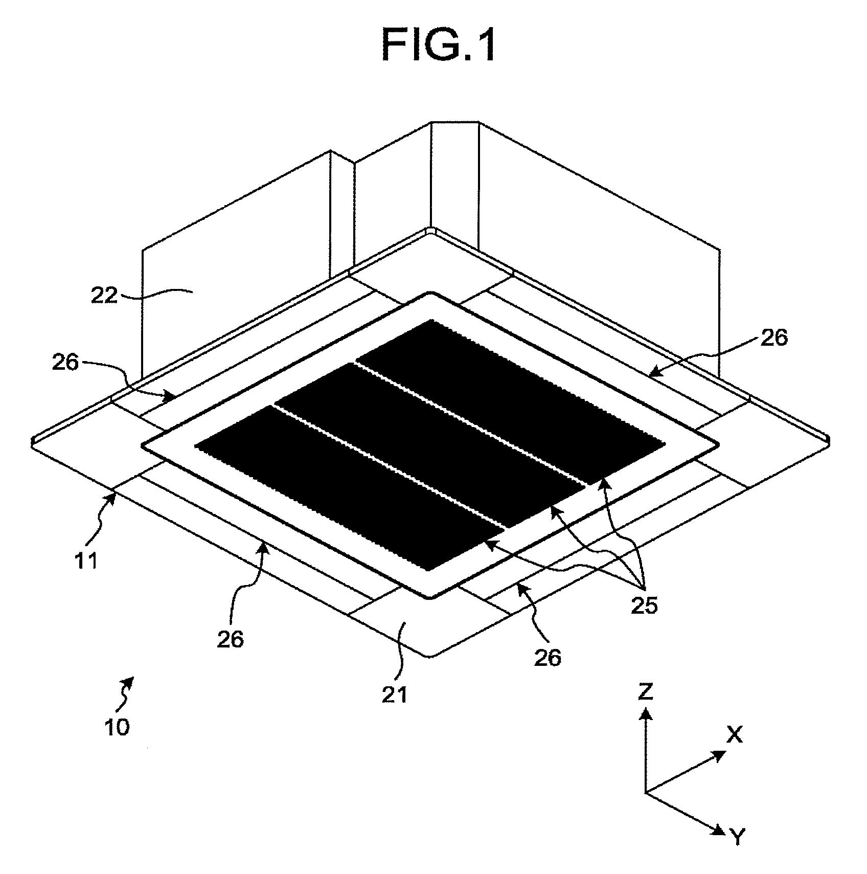
[0005] FIG. 1 is a perspective view illustrating an air conditioning apparatus in a first embodiment;
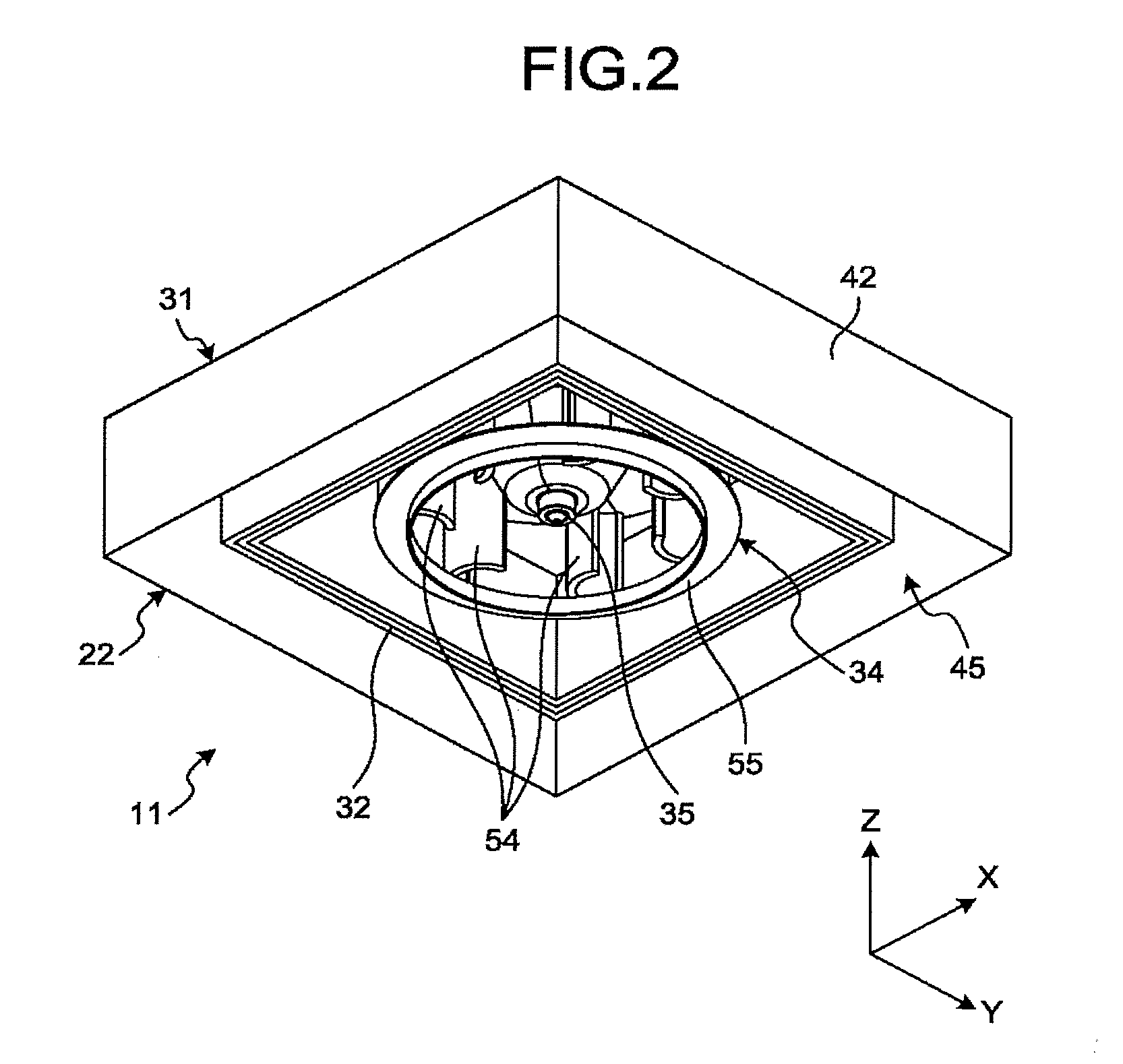
[0006] FIG. 2 is a perspective view illustrating a main body of an indoor unit in the first embodiment;
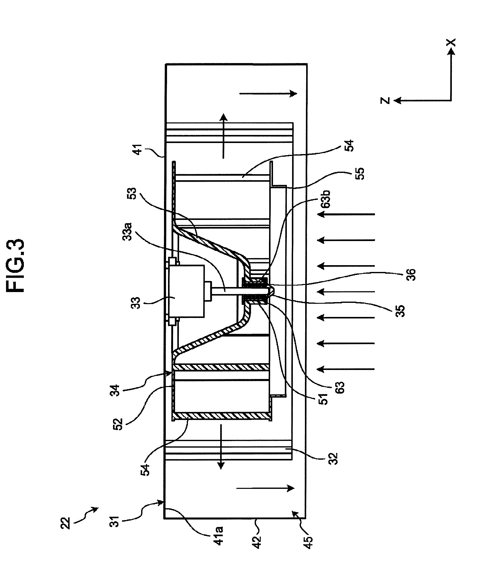
[0007] FIG. 3 is a cross-sectional view illustrating the main body of the indoor unit in the first embodiment;
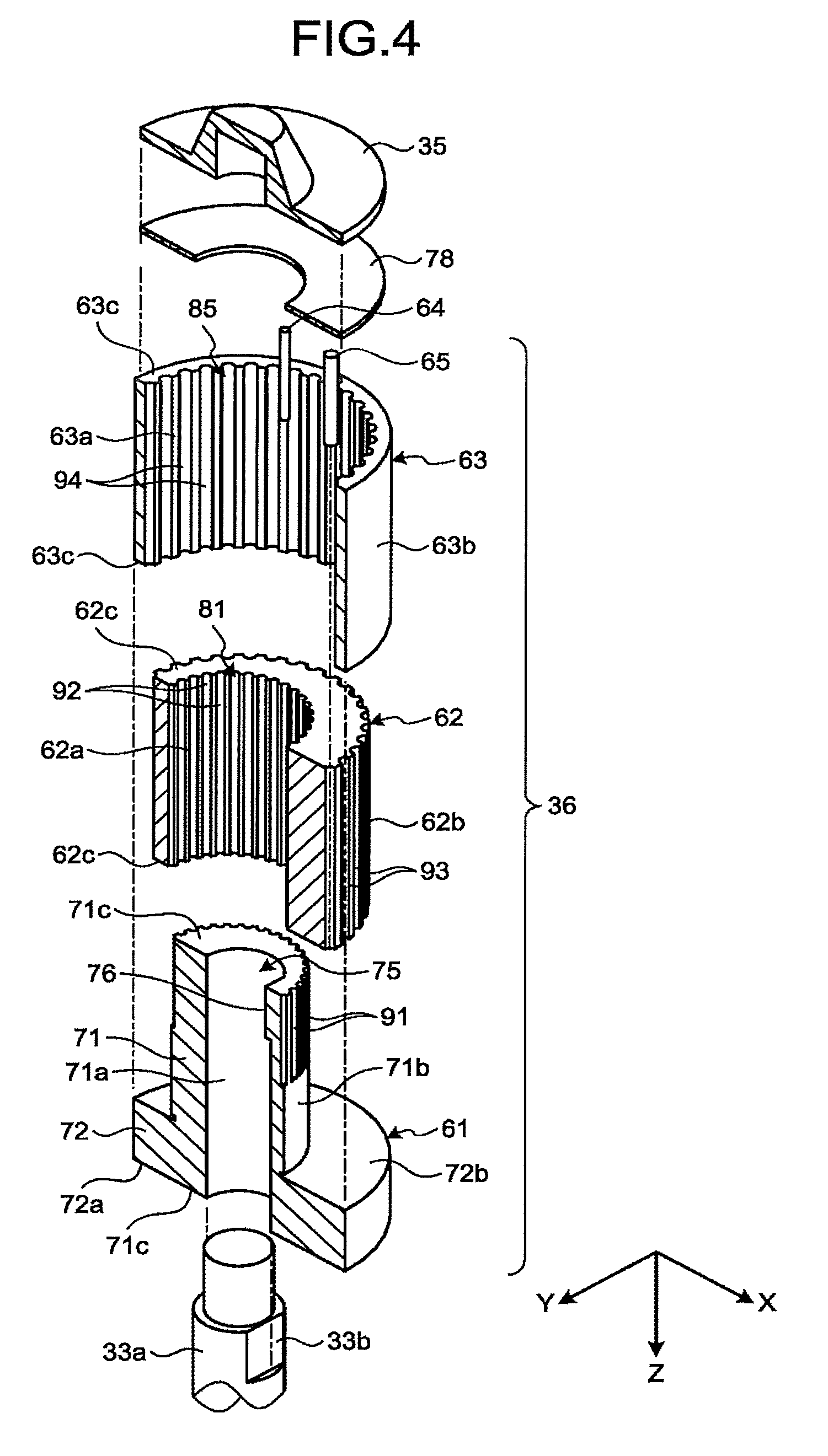
[0008] FIG. 4 is an exploded perspective view schematically illustrating a shaft of a motor and a bushing in the first embodiment;
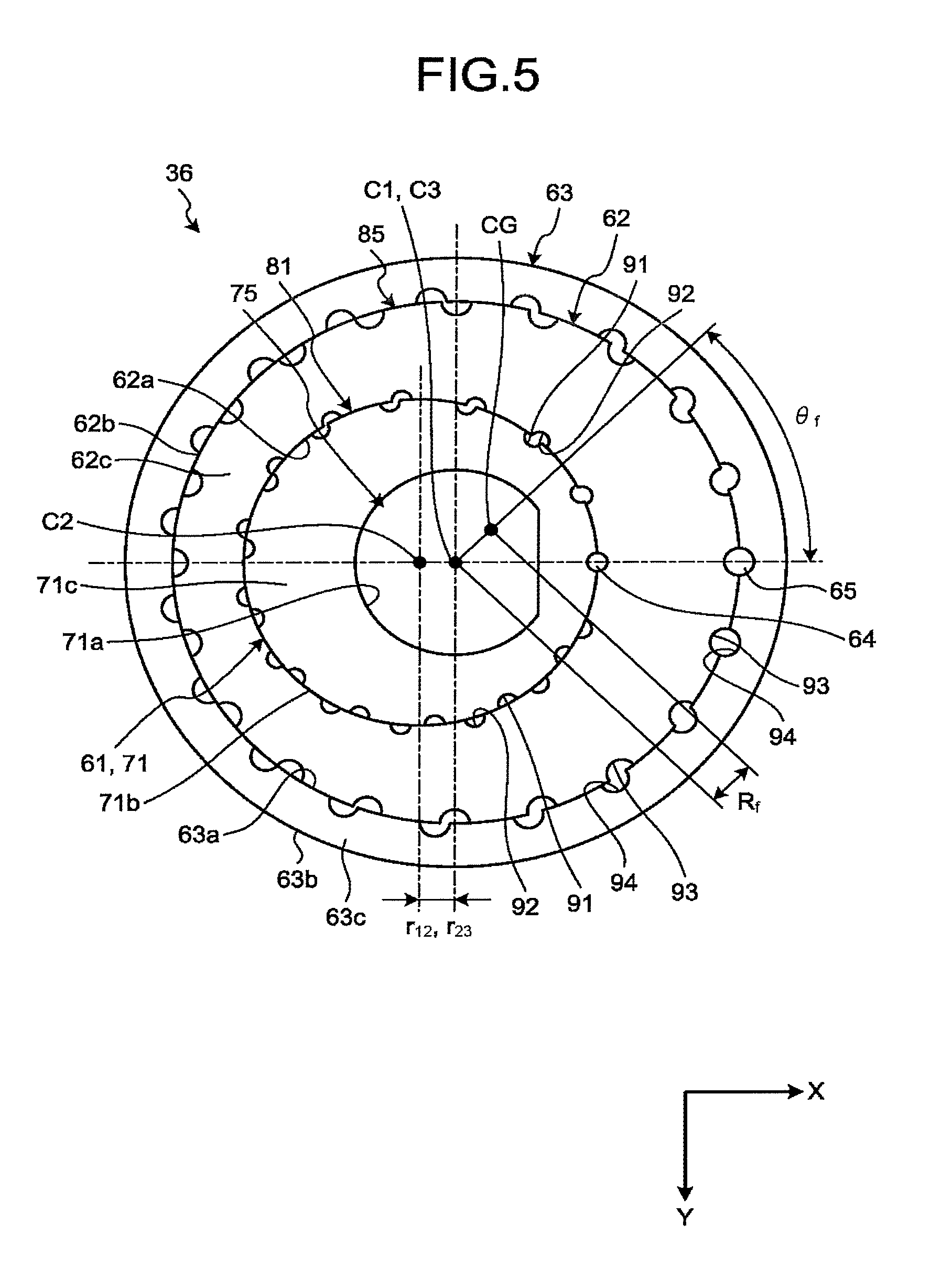
[0009] FIG. 5 is a plan view illustrating the bushing in the first embodiment;
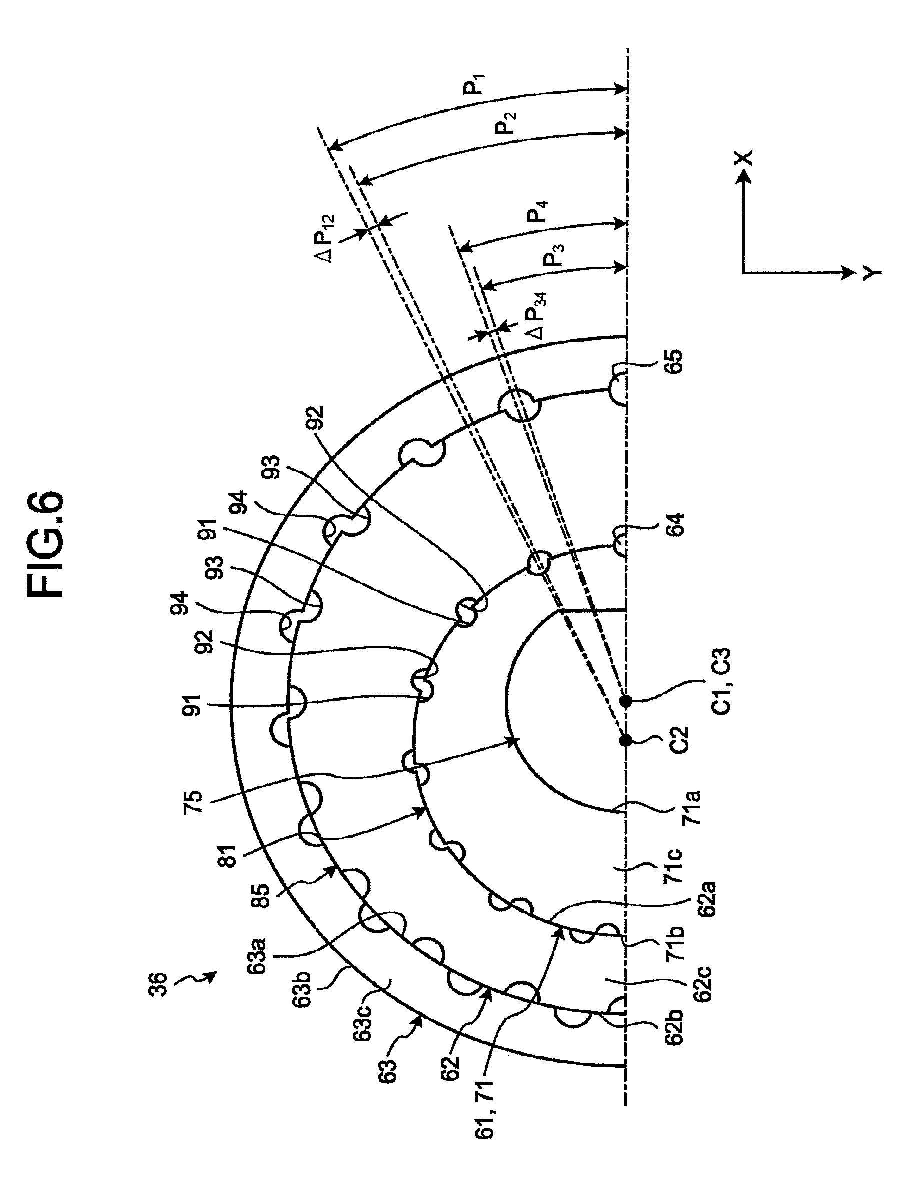
[0010] FIG. 6 is a plan view illustrating a part of the bushing in the first embodiment;
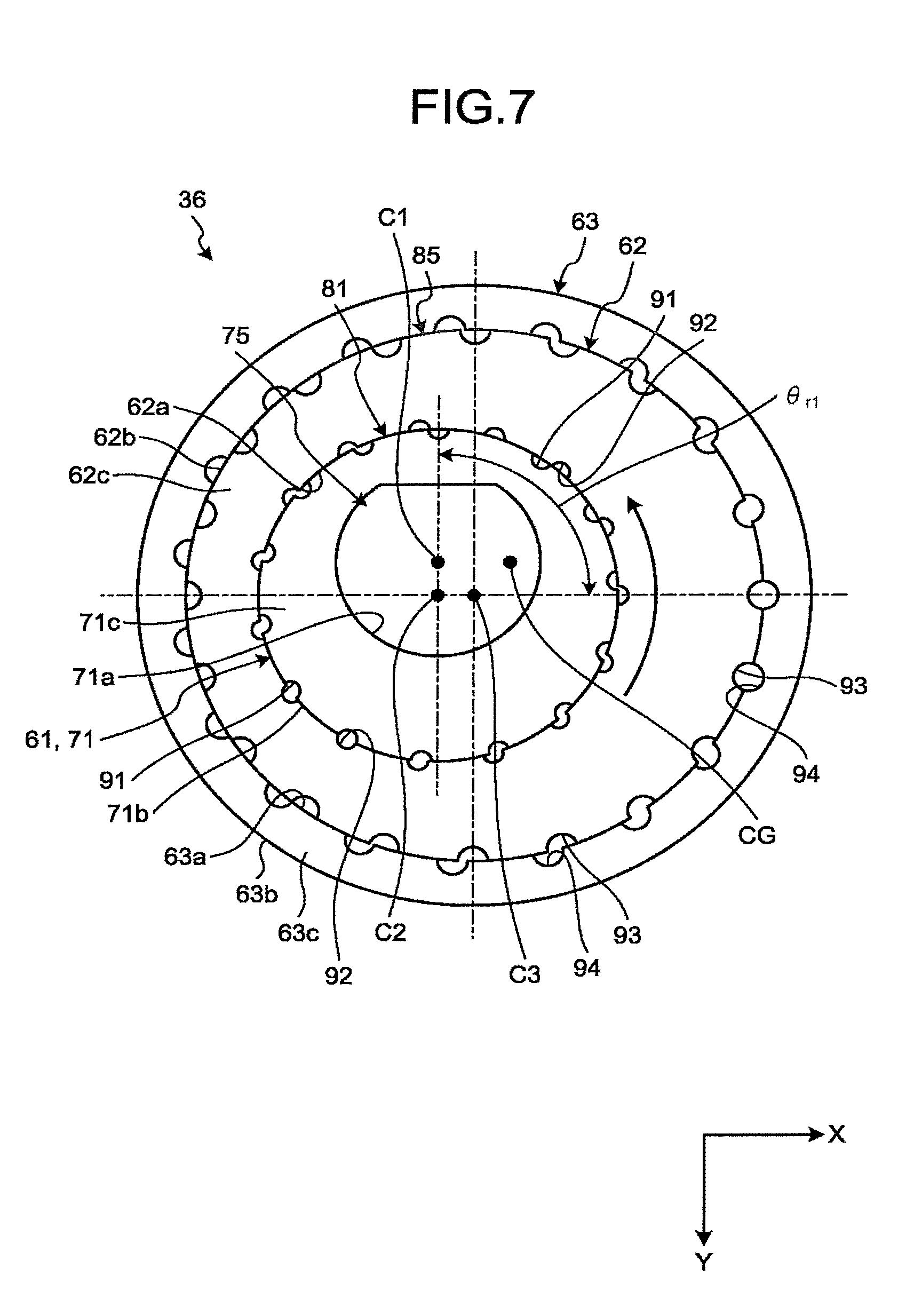
[0011] FIG. 7 is a plan view illustrating the bushing in which a first member is rotated in the first embodiment;
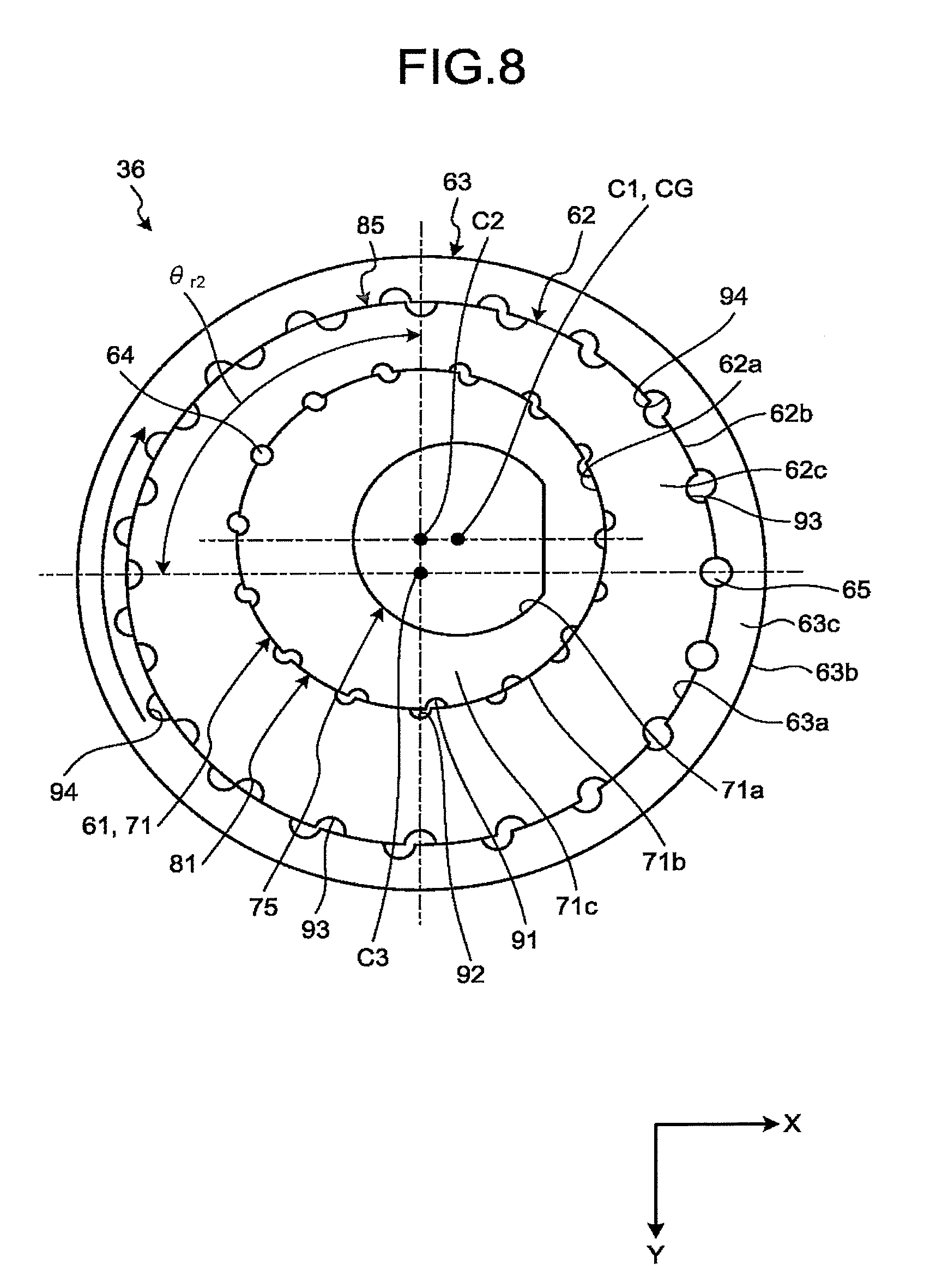
[0012] FIG. 8 is a plan view illustrating the bushing in which a second member is rotated in the first embodiment;
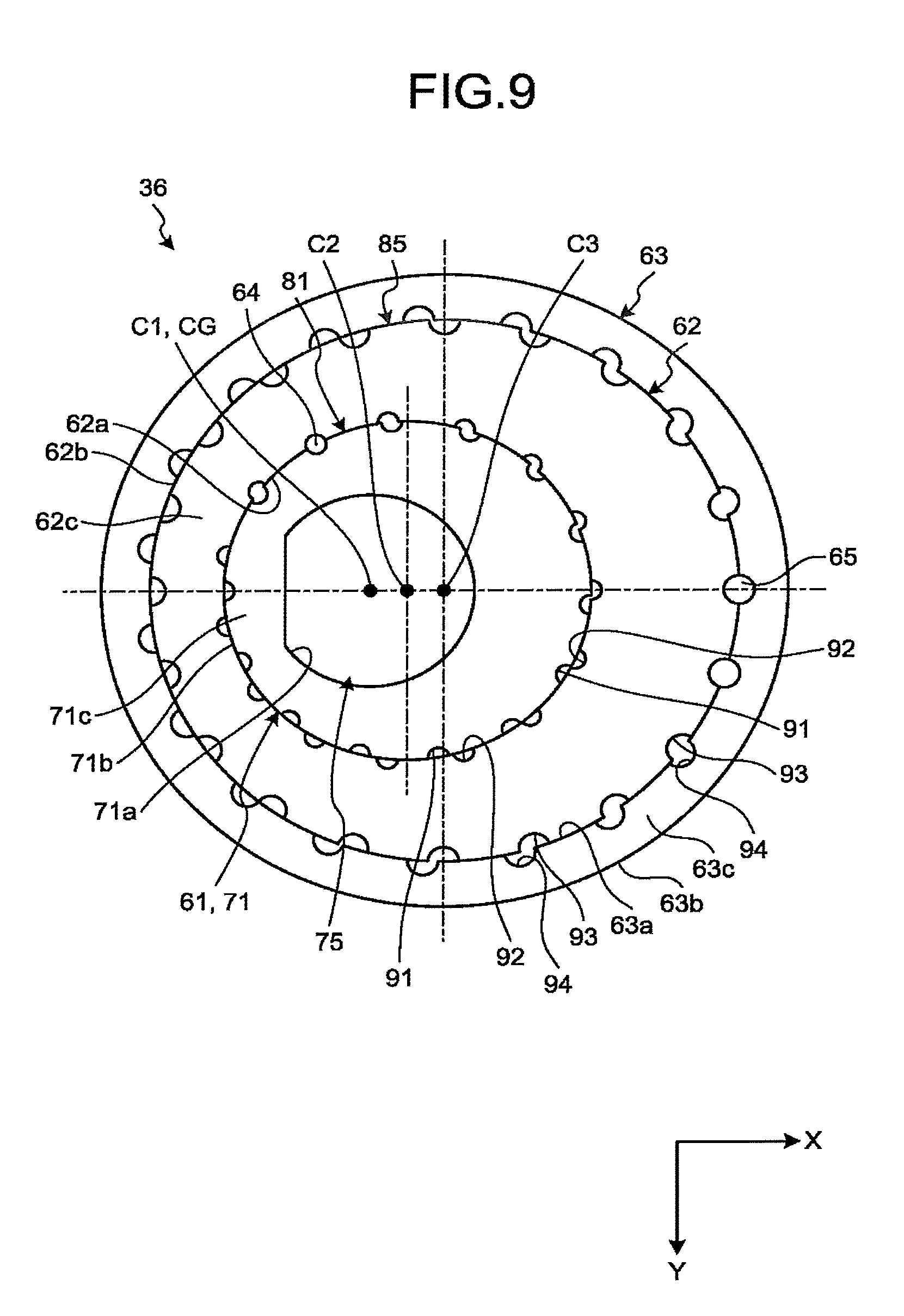
[0013] FIG. 9 is a plan view illustrating another example of the bushing in the first embodiment;
[0014] FIG. 10 is a plan view illustrating a part of the bushing according to a second embodiment;
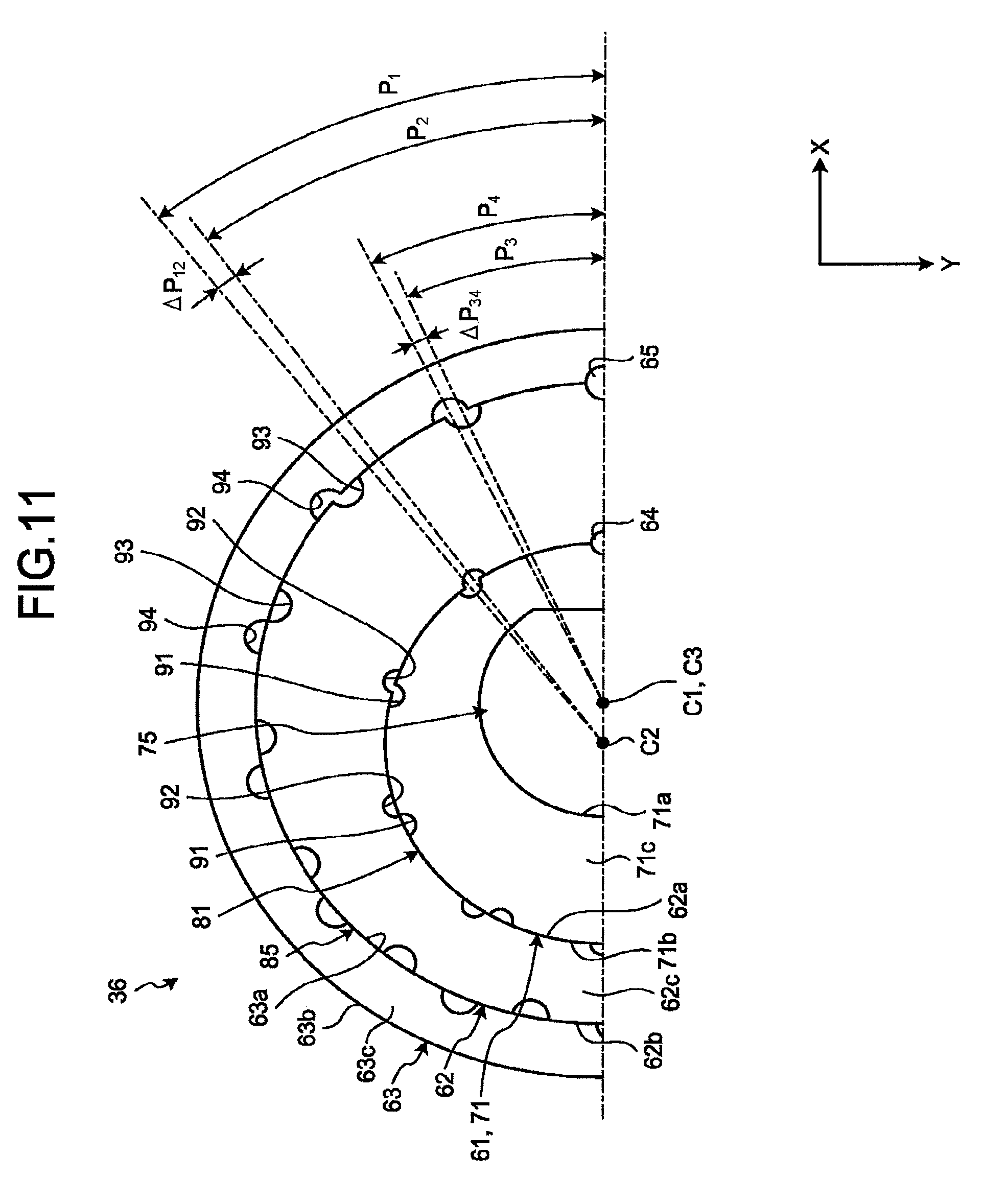
[0015] FIG. 11 is a plan view illustrating a part of the bushing according to a third embodiment; and
[0016] FIG. 12 is a plan view illustrating a part of the bushing according to a fourth embodiment.
DETAILED DESCRIPTION
[0017] According to one embodiment, a mounting structure includes a first member, a second member, a third member, a first limiting member and a second limiting member. The first member includes a first inner surface and a first outer surface. The first inner surface extends along and around a first axis, at least a part of the first inner surface which forms a first hole. The first outer surface is opposite the first inner surface, extends along and around a second axis different from the first axis, and is provided with one or more first dents arranged around the second axis at an interval of a first angular distance. The second member includes a second inner surface and a second outer surface. The second inner surface extends along and around the second axis and is provided with one or more second dents arranged around the second axis at an interval of a second angular distance different from the first angular distance, at least a part of the second inner surface which forms a second hole that allows the first member to be housed, in contact with the first outer surface of the first member. The second outer surface is opposite the second inner surface, extends along and around a third axis different from the second axis, and is provided with one or more third dents arranged around the third axis at an interval of a third angular distance. The third member includes a third inner surface that extends along and around the third axis and is provided with one or more fourth dents arranged around the third axis at an interval of a fourth angular distance different from the third angular distance, at least a part of the third inner surface which forms a third hole that allows the second member to be housed, in contact with the second outer surface of the second member. The first limiting member is housed in one of the one or more first dents and one of the one or more second dents opposing each other, and limits rotation of the first member and the second member around the second axis. The second limiting member is housed in one of the one or more third dents and one of the one or more fourth dents opposing each other, and limits rotation of the second member and the third member around the third axis.
First Embodiment
[0018] The following describes a first embodiment with reference to FIGS. 1 to 9. In the present specification, constituting elements according to the embodiments and descriptions thereof are described with multiple expressions in some cases. The constituting elements and descriptions thereof described with multiple expressions may be described with other expressions other than those described herein. In addition, constituting elements and descriptions thereof that are not described with multiple expressions may also be described with other expressions other than those described herein.
[0019] FIG. 1 is a perspective view illustrating an air conditioning apparatus (hereinafter, referred to as an air conditioner) 10 in the first embodiment. The air conditioner 10 is an example of an air conditioning apparatus and rotational machinery. The air conditioner 10 can also be referred to as an air handling unit, for example. The rotational machinery is not limited to the air conditioner 10. Examples of the rotational machinery may include a mechanism having an industrial motor, a home electrical appliance such as an electric fan or a washing machine, and other machines having a power source and a rotational object.
[0020] As illustrated in each drawing, an X-axis, a Y-axis, and a Z-axis are defined in the specification. The X-axis, the Y-axis, and the Z-axis are orthogonal to one another. The X-axis is along the width of the air conditioner 10. The Y-axis is along the length (the depth) of the air conditioner 10. The Z-axis is along the height of the air conditioner 10.
[0021] As illustrated in FIG. 1, the air conditioner 10 includes an indoor unit 11. The indoor unit 11 is connected to an outdoor condensing unit and a controller that controls the indoor unit 11 and the outdoor condensing unit, for example. The air conditioner 10 may be constructed as an air conditioning system including two or more indoor units 11 connected to a single controller.
[0022] The indoor unit 11 includes a cover 21 and a main body 22. The cover 21 is provided on the ceiling of a room in which the indoor unit 11 is installed, for example. The cover 21 is provided with a plurality of air inlets 25 and a plurality of air outlets 26. The air outlets 26 can be opened or closed by a louver, for example.
[0023] FIG. 2 is a perspective view illustrating the main body 22 of the indoor unit 11 in the first embodiment. FIG. 3 is a cross-sectional view illustrating the main body 22 of the indoor unit 11 in the first embodiment. As illustrated in FIGS. 2 and 3, the main body 22 includes a housing 31, a heat exchanger 32, a motor 33, a turbofan 34, a cap 35, and a bushing 36. The motor 33 is an example of the power source. The turbofan 34 is an example of a rotational object and a fan. The turbofan 34 can also be referred to as a centrifugal fan, for example. The rotational object is not limited to the turbofan 34. The rotational object may be another fan such as a propeller fan or another rotational object such as a gear or a pulley, for example. The bushing 36 is an example of a mounting structure. The bushing 36 can also be referred to as a connecting component, a bearing, or a member, for example.
[0024] As illustrated in FIG. 3, the housing 31 is formed of a metal, for example, and includes a top wall 41 and a peripheral wall 42. The top wall 41 is plate-like lying in the X-Y plane. The top wall 41 may be provided with ribs to increase the stiffness of the top wall 41, for example. The peripheral wall 42 is tubular in shape, extending from the edges of the top wall 41 in a negative Z-axis direction (oppositely to the arrow of the Z-axis or downward).
[0025] The housing 31 includes an air passage 45 inside. The air passage 45 may be formed by the housing 31 or a member mounted inside the housing 31, for example. The top wall 41 has an inner surface 41a that faces the air passage 45. The inner surface 41a faces in the negative Z-axis direction.
[0026] The heat exchanger 32 is disposed in the air passage 45. The heat exchanger 32 is attached to the inner surface 41a of the top wall 41 and has a tubular shape extending in the negative Z-axis direction, for example. The heat exchanger 32 includes piping through which refrigerant flows, and fins, for example. The heat exchanger 32 exchanges heat between air passing through the heat exchanger 32 and the refrigerant to warm or cool the air. The heat exchanger 32 is not limited to this example.
[0027] The motor 33 is a direct current (DC) motor the rotation speed of which can be changed by inverter control, for example. The motor 33 is mounted on the inner surface 41a of the top wall 41 with bolts extending from the inner surface 41a and nuts, for example.
[0028] The motor 33 has a shaft 33a. The shaft 33a can also be referred to as a drive shaft or a rotation shaft, for example. The shaft 33a extends in the negative Z-axis direction. The motor 33 is driven to rotate the shaft 33a around the central axis of the shaft 33a.
[0029] The turbofan 34 is surrounded by the heat exchanger 32 in the air passage 45. The turbofan 34 is made of a synthetic resin, for example. The turbofan 34 may be made of another material. The turbofan 34 includes a hub 51, a support 52, a connection 53, a plurality of blades 54, and a shroud 55.
[0030] The hub 51 has a tubular shape extending in the Z-axis direction. The hub 51 is mounted on the shaft 33a of the motor 33 through the bushing 36. The support 52 has an annular shape lying in the X-Y plane. The support 52 is disposed closer to the top wall 41 than the hub 51 and surrounds the motor 33.
[0031] The connection 53 has a tubular, substantially circular truncated cone shape, for example. The connection 53 connects the end of the hub 51 and the inner circumference of the support 52. The blades 54 are arranged in annular form and extend in the negative Z-axis direction from the support 52. The shroud 55 has an annular shape lying in the X-Y plane and is connected to the edges of the blades 54.
[0032] The motor 33 rotates the shaft 33a to rotate the turbofan 34. As illustrated with the arrows in FIG. 3, the turbofan 34, while rotating, sucks air in the room from the air inlets 25 illustrated in FIG. 1 and supplies the air to the heat exchanger 32. The air is warmed or cooled through the heat exchanger 32 and supplied to the room from the air outlets 26 illustrated in FIG. 1.
[0033] The cap 35 fixes the turbofan 34 and the bushing 36 to the shaft 33a of the motor 33. The cap 35 is threadably attached to a male screw in the distal end of the shaft 33a to support the turbofan 34 and the bushing 36, for example.
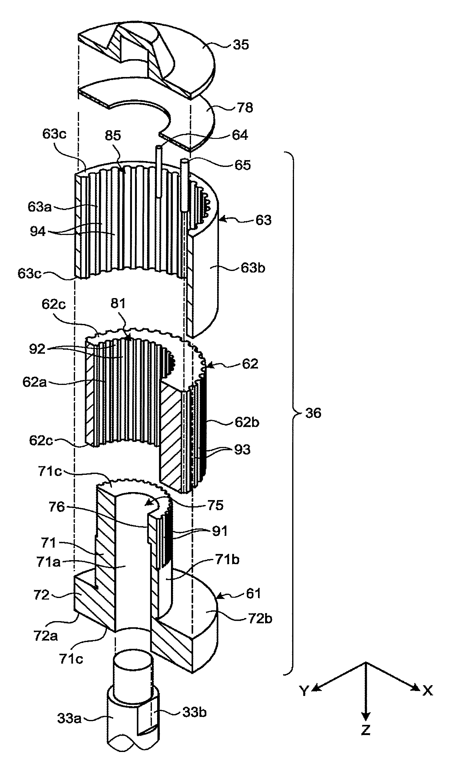
[0034] FIG. 4 is an exploded perspective view schematically illustrating the shaft 33a of the motor 33 and the bushing 36 in the first embodiment. FIG. 4 illustrates a cross section of the bushing 36. As illustrated in FIG. 4, the bushing 36 includes a first member 61, a second member 62, a third member 63, a first pin 64, and a second pin 65. The first pin 64 is an example of a first limiting member. The second pin 65 is an example of a second limiting member.
[0035] The first member 61, the second member 62, and the third member 63 are made of a relatively lightweight metal such as an aluminum alloy, for example. The first member 61, the second member 62, and the third member 63 are made of the same material.
[0036] The first member 61, the second member 62, and the third member 63 may be made of another material such as a synthetic resin. The first member 61, the second member 62, and the third member 63 may be made of materials different from one another.
[0037] The first member 61 has a tube 71 and a flange 72. The tube 71 has a substantially cylindrical shape extending in the Z-axis direction. The tube 71 is, thus, provided with a first hole 75 that extends through the tube 71 in the Z-axis direction. The first hole 75 is not limited to a through hole in the tube 71. The first hole 75 may have a bottom.
[0038] FIG. 5 is a plan view illustrating the bushing 36 in the first embodiment. As illustrated in FIG. 5, the first hole 75 has a substantially circular cross section having the center matching the first central axis C1. The first central axis C1 is an example of first axis. The first central axis C1 is a virtual central axis of the first hole 75 extending along the Z-axis. The first hole 75 has a substantially circular hole extending about the first central axis C1. In other words, the first hole 75 extends along and around the first central axis C1. In the first embodiment, the first central axis C1 substantially coincides with the central axis of the shaft 33a of the motor 33. The first central axis C1 can also be referred to as a rotation center.
[0039] As illustrated in FIG. 4, the tube 71 includes a first inner circumferential surface 71a, a first outer circumferential surface 71b, and two first end faces 71c. The first inner circumferential surface 71a is an example of a first inner surface. The first outer circumferential surface is an example of a first outer surface. The first inner circumferential surface 71a sections (defines) the first hole 75 and has a substantially cylindrical shape extending about the center matching the first central axis C1. In other words, the first inner circumferential surface 71a forms the first hole 75. A part of the first inner circumferential surface 71a may form the first hole 75. The first inner circumferential surface 71a has a substantially cylindrical face extending along and around the first central axis C1. The first inner circumferential surface 71a faces the inside of the first hole 75. The first hole 75 is provided inside the first inner circumferential surface 71a.
[0040] The first outer circumferential surface 71b is opposite the first inner circumferential surface 71a. As illustrated in FIG. 5, the first outer circumferential surface 71b has a substantially cylindrical shape extending about the center matching a second central axis C2. In other words, the first outer circumferential surface 71b is a substantially cylindrical face extending along and around the second central axis C2. The second central axis is an example of a second axis.
[0041] The second central axis C2 is a virtual central axis of the first outer circumferential surface 71b extending along the Z-axis. The second central axis C2 is in parallel with the first central axis C1 and located at a different position from the first central axis C1. In other words, the second central axis C2 differs from the first central axis C1. The first inner circumferential surface 71a and the first hole 75 are eccentric from the first outer circumferential surface 71b. The second central axis C2 may be tilted with respect to the first central axis C1.
[0042] The substantially cylindrical first outer circumferential surface 71b about the second central axis C2 is thus in rotational symmetry with respect to the second central axis C2. The second central axis C2 is also a symmetrical axis of the first outer circumferential surface 71b.
[0043] As illustrated in FIG. 4, the two first end faces 71c face in the positive (as indicated by the arrow of the Z-axis or upward) and negative Z-axis directions. The first hole 75 opens to the two first end faces 71c.
[0044] The tube 71 is provided with a fitting 76. The fitting 76 projects from the first inner circumferential surface 71a toward the inside of the first hole 75. The length of the fitting 76 is shorter than that of the first hole 75 in the Z-axis direction. In other words, the fitting 76 is provided on a part of the first inner circumferential surface 71a in the Z-axis direction. The fitting 76 is not limited to this example.
[0045] A part of the first inner circumferential surface 71a may be provided with a depression or a projection such as the fitting 76 as described in the first embodiment. In this case, the first central axis C1 passes the center of a circular cross section part with no depression or projection, of the first hole 75. Alternatively, the first inner circumferential surface 71a may be provided with a depression or a projection on the entire first inner circumferential surface 71a in the Z-axis direction. In this case, the first central axis C1 passes the center of an arc-shaped part in the cross section of the first hole 75. When the cross section of the first hole 75 includes two or more arc-shaped parts, the first central axis C1 passes the center of an arc-shaped part of the cross section having the center closest to the geometric center (centroid) of the cross section of the first hole 75.
[0046] In the above, the cross section of the first hole 75 is the circular or includes arc-shaped part. However, the cross section of the first hole 75 may have no arc-shaped part. In this case, the first central axis C1 passes the symmetrical axis of a rotationally symmetric cross section with no depression or projection, of the first hole 75. Depressions or projections may be provided on the entirety of the first inner circumferential surface 71a in the Z-axis direction. In this case, the first central axis C1 passes the symmetrical axis of a largest rotationally symmetric part in the cross section of the first hole 75. When the shape of the first hole 75 is not any of the examples above, the first central axis C1 passes the geometric center of the cross section of the first hole 75.
[0047] The shaft 33a of the motor 33 is inserted into the first hole 75. The shaft 33a is what is called a D-cut shaft with a cutout 33b. The fitting 76 is fitted into the cutout 33b while the shaft 33a is inserted into the first hole 75. As a result, the rotation of the shaft 33a is transmitted to the first member 61.
[0048] The flange 72 projects from the first outer circumferential surface 71b of the tube 71. The flange 72 is substantially circular plate-like lying in the X-Y plane. The flange 72 may have another shape.
[0049] The flange 72 projects from the end of the first outer circumferential surface 71b in the positive Z-axis direction. The flange 72 has a first surface 72a and a second surface 72b. The first surface 72a is substantially flat, facing in the positive Z-axis direction. The first surface 72a are continuous with one of the first end faces 71c. The second surface 72b is opposite the first surface 72a and substantially flat, facing in the negative the Z-axis direction.
[0050] The second member 62 has a substantially cylindrical shape extending in the Z-axis direction. The second member 62 is thus provided with a second hole 81 that extends through the second member 62 in the Z-axis direction. The second hole 81 is not limited to a through hole in the second member 62. The second hole 81 may have a bottom.
[0051] As illustrated in FIG. 5, the second hole 81 has a substantially circular cross section with the center matching the second central axis C2. The second central axis C2 is a virtual central axis of the second hole 81 extending along the Z-axis. The second hole 81 is a substantially circular hole, extending around the center matching the second central axis C2. In other words, the second hole 81 extends along and around the second central axis C2.
[0052] As illustrated in FIG. 4, the second member 62 includes a second inner circumferential surface 62a, a second outer circumferential surface 62b, and two second end faces 62c. The second inner circumferential surface 62a is an example of a second inner surface. The second outer circumferential surface 62b is an example of a second outer surface. The second inner circumferential surface 62a sections (defines) the second hole 81 and has a substantially cylindrical shape about the center coinciding with the second central axis C2. In other words, the second inner circumferential surface 62a forms the second hole 81. A part of the second inner circumferential surface 62a may form the second hole 81. That is, the second inner circumferential surface 62a is a substantially cylindrical face, extending along and around the second central axis C2. The second inner circumferential surface 62a faces the inside of the second hole 81. The second hole 81 is provided inside the second inner circumferential surface 62a.
[0053] The substantially cylindrical second inner circumferential surface 62a about the second central axis C2 is thus in rotational symmetry with respect to the second central axis C2. The second central axis C2 is also a symmetrical axis of the second inner circumferential surface 62a.
[0054] As described above, the center (the second central axis C2) of the second hole 81 and the second inner circumferential surface 62a and the center (the second central axis C2) of the first outer circumferential surface 71b of the tube 71 of the first member 61 substantially coincide with each other. Because of this, the second member 62 can rotate around the second central axis C2 with respect to the first member 61 while the first member 61 and the second member 62 are not fixed to each other and thus are movable.
[0055] The tube 71 of the first member 61 is housed in the second hole 81. A radius of the second hole 81 and a radius of the first outer circumferential surface 71b of the tube 71 of the first member 61 are practically equal to each other. The second inner circumferential surface 62a thus contact with the first outer circumferential surface 71b of the tube 71 housed in the second hole 81 and thereby limits the movement of the second member 62 with respect to the first member 61 in a direction intersecting the Z-axis. A part of the second inner circumferential surface 62a may be slightly apart from the first outer circumferential surface 71b.
[0056] The second outer circumferential surface 62b is opposite the second inner circumferential surface 62a. As illustrated in FIG. 5, the second outer circumferential surface 62b is a cylindrical face extending about a third central axis C3. The cylindrical second outer circumferential surface 62b extends along and around the third central axis C3. The third central axis C3 is an example of a third axis.
[0057] A third central axis C3 is a virtual central line of the second outer circumferential surface 62b extending along the Z-axis. The third central axis C3 is in parallel with the first central axis C1 and the second central axis C2, and located at a different position from the second central axis C2. In other words, the third central axis C3 differs from the second central axis C2. The second inner circumferential surface 62a and the second hole 81 are eccentric from the second outer circumferential surface 62b. The third central axis C3 may be tilted with respect to the first central axis C1. The third central axis C3 may be tilted with respect to the second central axis C2.
[0058] A distance r.sub.12 between the first central axis C1 and the second central axis C2 is substantially equal to a distance r.sub.23 between the second central axis C2 and the third central axis C3. As a result, as illustrated in FIG. 5, the first central axis C1 and the third central axis C3 can match each other.
[0059] The cylindrical second outer circumferential surface 62b extending about the third central axis C3 is then in rotational symmetry with respect to the third central axis C3. The third central axis C3 is also a symmetrical axis of the second outer circumferential surface 62b.
[0060] As illustrated in FIG. 4, the two second end faces 62c face in the positive and negative Z-axis directions, respectively. The second hole 81 opens to the two second end faces 62c. While the tube 71 is housed in the second hole 81, the second end face 62c facing in the positive Z-axis direction is in contact with the second surface 72b of the flange 72. The flange 72 supports the second member 62 to limit the movement of the second member 62 with respect to the first member 61 in the positive Z-axis direction.
[0061] The third member 63 has a substantially cylindrical shape extending in the Z-axis direction. The third member 63 is thus provided with a third hole 85 that extends through the third member 63 in the Z-axis direction. The third hole 85 is not limited to a through hole in the third member 63. The third hole 85 may have a bottom.
[0062] As illustrated in FIG. 5, the third hole 85 has a substantially circular cross section with the center matching the third central axis C3. The third central axis C3 is a virtual central axis of the third hole 85 extending along the Z-axis. The third hole 85 is a substantially circular hole, extending about the third central axis C3. The third hole 85 extends along and around the third central axis C3.
[0063] As illustrated in FIG. 4, the third member 63 includes a third inner circumferential surface 63a, a third outer circumferential surface 63b, and two third end faces 63c. The third inner circumferential surface 63a is an example of a third inner surface. The third inner circumferential surface 63a sections (defines) the third hole 85 and has a substantially cylindrical shape extending about the center matching the third central axis C3. In other words, the third inner circumferential surface 63a forms the third hole 85. A part of the third inner circumferential surface 63a may form the third hole 85. The third inner circumferential surface 63a is a substantially cylindrical face, extending along and around the third central axis C3. The third inner circumferential surface 63a faces the inside of the third hole 85. The third hole 85 is provided inside the third inner circumferential surface 63a. The second inner circumferential surface 62a and the second hole 81 are eccentric from the third inner circumferential surface 63a.
[0064] The substantially cylindrical third inner circumferential surface 63a extending about the third central axis C3 is in rotational symmetry with respect to the third central axis C3. The third central axis C3 is also a symmetrical axis of the third inner circumferential surface 63a.
[0065] As described above, the center (the third central axis C3) of the third hole 85 and the third inner circumferential surface 63a and the center (the third central axis C3) of the second outer circumferential surface 62b of the second member 62 practically coincide with each other. The third member 63 can thus rotate around the third central axis C3 with respect to the second member 62 when the second member 62 and the third member 63 are not fixed to each other and thus are movable.
[0066] The second member 62 is housed in the third hole 85. A radius of the third hole 85 and a radius of the second outer circumferential surface 62b of the second member 62 are practically equal to each other. The third inner circumferential surface 63a is thus in contact with the second outer circumferential surface 62b of the second member 62 housed in the third hole 85, and thereby limits the movement of the third member 63 with respect to the second member 62 in a direction intersecting the Z-axis. A part of the third inner circumferential surface 63a may be slightly apart from the second outer circumferential surface 62b.
[0067] The third outer circumferential surface 63b is opposite the third inner circumferential surface 63a. As illustrated in FIG. 5, the third outer circumferential surface 63b has a cylindrical shape extending about the center matching the third central axis C3. The center (the third central axis C3) of the third outer circumferential surface 63b and the center (the third central axis C3) of the third inner circumferential surface 63a practically coincide with each other. In other words, the third inner circumferential surface 63a and the third outer circumferential surface 63b are concentric.
[0068] The third outer circumferential surface 63b is a substantially cylindrical face extending along and around the third central axis C3. The third outer circumferential surface 63b is in rotational symmetry with the third central axis C3. The third central axis C3 is also a symmetrical axis of the third outer circumferential surface 63b.
[0069] As illustrated in FIG. 3, the third member 63 is formed integrally with the hub 51 of the turbofan 34 by insert molding, for example. In the first embodiment, the third outer circumferential surface 63b of the third member 63 is connected to the hub 51 of the turbofan 34. Alternatively, for example, the third member 63 and the turbofan 34 may be formed of the same material into a single component.
[0070] As illustrated in FIG. 4, the two third end faces 63c face in the positive and negative Z-axis directions, respectively. The third hole 85 opens to the two third end faces 63c. The tube 71 is housed in the second hole 81 while the second member 62 is housed in the third hole 85. As a result, the third end face 63c facing in the positive Z-axis direction is in contact with the second surface 72b of the flange 72. The flange 72 supports the third member 63 to limit the movement of the third member 63 with respect to the first member 61 in the positive Z-axis direction.
[0071] While the tube 71 is housed in the second hole 81 and the second member 62 is housed in the third hole 85, the first end face 71c, the second end face 62c, and the third end face 63c, facing in the Z-axis negative direction, form substantially the same plane. The cap 35 attached to the shaft 33a supports the first end face 71c, the second end face 62c, and the third end face 63c, facing in the Z-axis negative direction, and limits the movement of the second member 62 and the third member 63 with respect to the first member 61 in the negative Z-axis direction.
[0072] A sheet 78 may be interposed between the cap 35, and the first member 61, the second member 62, and the third member 63. The sheet 78 is a substantially annular sheet, formed of an elastic material such as a synthetic rubber, for example. Owing to the sheet 78, the cap 35 can stably support the first end face 71c, the second end face 62c, and the third end face 63c, facing in the negative Z-axis direction, even when having a difference in level.
[0073] FIG. 6 is a plan view illustrating a part of the bushing 36 in the first embodiment. As illustrated in FIG. 6, the first member 61 is provided with a plurality of first dents 91 on the first outer circumferential surface 71b. The first dents 91 can be referred to as grooves, depressions, or cutouts, for example.
[0074] The first dents 91 are grooves with a substantially semi-circle cross section, extending in the Z-axis direction. The first dents 91 may have another shape. The first dents 91 open to the first outer circumferential surface 71b and the first end face 71c of the tube 71 facing in the negative Z-axis direction.
[0075] The first dents 91 are arranged around the second central axis C2 at a first pitch P.sub.1. In other words, the first dents 91 are aligned around the second central axis C2 at intervals of a constant angle (the first pitch P.sub.1). The first pitch P.sub.1 is an example of a first angular distance and a fourth angle .theta..sub.4. The first pitch P.sub.1 corresponds to a difference in angles between the adjacent first dents 91 around the second central axis C2. In the first embodiment, the first pitch P.sub.1 is set to 25 degrees.
[0076] The difference in angles between the adjacent first dents 91 may differ from the first pitch P.sub.1. For example, when the first pitch P.sub.1 differs from a divisor of 360-degree angle, and the first dents 91 are arranged around the second central axis C2 at the first pitch P.sub.1 in order, the difference in angles between the initially arranged first dent 91 and the last-arranged first dent 91 differs from the first pitch P.sub.1.
[0077] The second member 62 is provided with a plurality of second dents 92 on the second inner circumferential surface 62a. The second member 62 is also provided with a plurality of third dents 93 on the second outer circumferential surface 62b. The second dents 92 and the third dents 93 can also be referred to as grooves, depressions, or cutouts, for example.
[0078] The second dents 92 are grooves with a substantially semi-circle cross section, extending in the Z-axis direction. The second dents 92 may have another shape. A radius of the second dents 92 is substantially equal to that of the first dents 91. The second dent 92 opens to the second inner circumferential surface 62a and to both the second end faces 62c of the second member 62.
[0079] The second dents 92 are arranged around the second central axis C2 at a second pitch P.sub.2. The second pitch P.sub.2 is an example of a second angular distance and a third angle .theta..sub.3. The second pitch P.sub.2 corresponds to a difference in angles between the adjacent second dents 92 around the second central axis C2. In the first embodiment, the second pitch P.sub.2 is set to 24 degrees. That is, the second pitch P.sub.2 differs from the first pitch P.sub.1. As with the first dents 91, a difference in angles between the adjacent second dents 92 may differ from the second pitch P.sub.2.
[0080] The third dents 93 are grooves with a substantially semi-circle cross section, extending in the Z-axis direction. The third dent 93 may have another shape. The third dent 93 opens to the second outer circumferential surface 62b and to both the second end faces 62c of the second member 62.
[0081] The third dents 93 are arranged around the third central axis C3 at a third pitch P.sub.3. The third pitch P.sub.3 is an example of a third angular distance and a first angle .theta..sub.1. The third pitch P.sub.3 corresponds to a difference in angles between the adjacent third dents 93 around the third central axis C3. In the first embodiment, the third pitch P.sub.3 is set to 18 degrees. As with the first dents 91, the difference in angles between the adjacent third dents 93 may differ from the third pitch P.sub.3.
[0082] The third member 63 is provided with a plurality of fourth dents 94 on the third inner circumferential surface 63a. The fourth dents 94 can also be referred to as grooves, depressions, or cutouts, for example. The fourth dents 94 are grooves with a substantially semi-circle cross section, extending in the Z-axis direction. The fourth dents 94 may have another shape. A radius of the fourth dents 94 is substantially equal to that of the third dents 93. The fourth dent 94 opens to the third inner circumferential surface 63a and to both the third end faces 63c of the third member 63.
[0083] The fourth dents 94 are arranged around the third central axis C3 at a fourth pitch P.sub.4. The fourth pitch P.sub.4 is an example of a fourth angular distance and a second angle .theta..sub.2. The fourth pitch P.sub.4 corresponds to a difference in angles between the adjacent fourth dents 94 around the third central axis C3. In the first embodiment, the fourth pitch P.sub.4 is set to 19 degrees. The fourth pitch P.sub.4 differs from the third pitch P.sub.3. The first pitch P.sub.1, the second pitch P.sub.2, the third pitch P.sub.3, and the fourth pitch P.sub.4 are all larger than zero degree and smaller than 360 degrees. As with the first dents 91, the difference in angles between the adjacent fourth dents 94 may differ from the fourth pitch P.sub.4.
[0084] As illustrated in FIG. 4, the first pin 64 and the second pin 65 both have a substantially columnar shape. The first pin 64 and the second pin 65 may have another shape. A radius of the first pin 64 is substantially equal to that of the first dents 91 and that of the second dents 92. A radius of the second pin 65 is substantially equal to that of the third dents 93 and that of the fourth dents 94.
[0085] As illustrated in FIG. 5, the first pin 64 is housed in one of the first dents 91 and one of the second dents 92 opposing each other. The first pin 64 limits a relative rotation between the first member 61 and the second member 62 around the second central axis C2. The first member 61 and the second member 62 thus mutually transmit torque, and are integrally rotatable around the second central axis C2.
[0086] The second pin 65 is housed in one of the third dents 93 and one of the fourth dents 94 opposing each other. The second pin 65 limits a relative rotation between the second member 62 and the third member 63 around the third central axis C3. The second member 62 and the third member 63 thus mutually transmit torque and are integrally rotatable around the third central axis C3.
[0087] The first member 61, the second member 62, and the third member 63 described above are assembled in accordance with the position of the gravity center of the turbofan 34 integrated with the third member 63. Specifically, the first member 61, the second member 62, and the third member 63 are arranged to rotate around their respective centers (the second central axis C2 or the third central axis C3) with the central axis of the shaft 33a of the motor 33 matching the gravity center of the turbofan 34. In other words, the first central axis C1 and the gravity center of the turbofan 34 are made coincident with each other.
[0088] To measure the position of the gravity center of the turbofan 34, the turbofan 34 is placed on three triangularly-arranged pressure sensors. Alternatively, the position of the gravity center of the turbofan 34 may be measured by rotating the turbofan 34.
[0089] With the first central axis C1 and the gravity center of the turbofan 34 coinciding with each other, the first pin 64 is housed in the opposing first dent 91 and second dent 92 while the second pin 65 is housed in the opposing third dent 93 and fourth dent 94. Thereby, the shaft 33a of the motor 33 can transmit the rotation (torque) to the turbofan 34 via the first member 61, the second member 62, and the third member 63.
[0090] The gravity center of the turbofan 34 may be located at any position on the first central axis C1 along the Z-axis. The position of the gravity center of the turbofan 34 can coincide with the first central axis C1 in a plan view in the extending direction of the first central axis C1 (the positive or negative Z-axis direction).
[0091] Due to the first central axis C1 and the gravity center of the turbofan 34 coinciding with each other, it is possible to prevent the rotating turbofan 34 from causing vibration. If the first central axis C1 differs from the gravity center of the turbofan 34, the vibration from the rotating turbofan 34 can be reduced by setting the first central axis C1 closer to the gravity center of the turbofan 34.
[0092] For example, with the gravity center of the turbofan 34 coinciding with the third central axis C3 being the center of the turbofan 34 and the third member 63, the first member 61, the second member 62, and the third member 63 are placed as illustrated in FIG. 5. The first central axis C1 and the third central axis C3 match each other. In this case, the position of the second central axis C2 may differ from the position in FIG. 5.
[0093] By the arrangement of the first member 61, the second member 62, and the third member 63 as illustrated in FIG. 5, the central axis (the first central axis C1) of the shaft 33a of the motor 33 substantially coincides with the position of the gravity center of the turbofan 34 (the third central axis C3). This can prevent the occurrence of vibration from the turbofan 34 in rotation.
[0094] Misalignment of the third member 63 by insert molding may, for example, lead to the deviation of the gravity center of the turbofan 34 from the third central axis C3. In this case, the first member 61, the second member 62, and the third member 63 are rotated around their respective centers (the second central axis C2 or the third central axis C3) from their positions illustrated in FIG. 5. The following describes position alignment between the first central axis C1 and a gravity center CG which is differently positioned from the third central axis C3. For the purpose of explanation, the first central axis C1 and the third central axis C3 initially coincide with each other as illustrated in FIG. 5. The position alignment between the gravity center CG and the first central axis C1 is not limited to this example.
[0095] The position of the gravity center CG is represented by polar coordinates (R.sub.f,.theta..sub.f) with reference to the third central axis C3 as the origin. The gravity center CG is separated from the third central axis C3 with a distance R.sub.f and at an angle .theta..sub.f around the third central axis C3 from the position illustrated in FIG. 5.
[0096] FIG. 7 is a plan view illustrating the bushing 36 in which the first member 61 is rotated in the first embodiment. As illustrated in FIG. 7, the first member 61 is rotated around the second central axis C2 by an angle GO with respect to the second member 62. The rotation results in changing a distance between the first central axis C1 and the third central axis C3 and placing the first central axis C1 apart from the third central axis C3 by a distance R.sub.f. That is, the first member 61 is rotated around the second central axis C2 with respect to the second member 62 to adjust an amount of eccentricity of the first central axis C1 with respect to the third central axis C3.
[0097] FIG. 8 is a plan view illustrating the bushing 36 in which the second member 62 is rotated in the first embodiment. Next, the second member 62 is rotated around the third central axis C3 by an angle .theta..sub.r2 with respect to the third member 63. The rotation results in changing the angle of the first central axis C1 with respect to the third central axis C3 and placing the first central axis C1 at the polar coordinates (R.sub.f,.theta..sub.f), which matches the gravity center CG. That is, the second member 62 is rotated around the third central axis C3 with respect to the third member 63 to adjust an angle of eccentricity of the first central axis C1 with respect to the third central axis C3.
[0098] The rotation angle .theta..sub.r1 of the first member 61 for placing the first central axis C1 at the polar coordinates (R.sub.f,.theta..sub.f) is found by the following expression 1:
R.sub.f=r {square root over (2(1-cos .theta..sub.r1))} Expression 1
That is, the first member 61 is rotated around the second central axis C2 with respect to the second member 62 in accordance with an eccentric distance R.sub.f between the gravity center CG and the third central axis C3.
[0099] The rotation angle 682 of the second member 62 for placing the first central axis C1 at the polar coordinates R.sub.f,.theta..sub.f) is found by the following expression 2:
.theta. f = .theta. r 2 - tan - 1 sin .theta. r 1 1 - cos .theta. r 1 + .pi. Expression 2 ##EQU00001##
The second member 62 is rotated around the third central axis C3 with respect to the third member 63 in accordance with an eccentric angle .theta..sub.f between the gravity center CG and the third central axis C3.
[0100] The rotation of the first member 61 and the second member 62 as described above allows the central axis of the shaft 33a of the motor 33 and the gravity center CG of the turbofan 34 to substantially coincide with each other. In this case, the turbofan 34 and the shaft 33a of the motor 33 appear to be eccentric from each other, however, vibration from the rotating turbofan 34 is reduced.
[0101] FIG. 9 is a plan view illustrating another example of the bushing 36 in the first embodiment. In the example illustrated in FIG. 9, the eccentric distance R.sub.f between the gravity center CG and the third central axis C3 is set to a maximum value that allows the bushing 36 to place the first central axis C1 and the gravity center CG at the same position. The first member 61 is rotated with respect to the second member 62 by 180 degrees, which places the first central axis C1 at the same position as the gravity center CG illustrated in FIG. 9.
[0102] In the example in FIG. 9, the eccentric distance R.sub.f is represented by the following expression 3:
R.sub.f=r.sub.12+r.sub.23=2r.sub.12=2r.sub.23 Expression 3
[0103] From the expression 3, it can be understood that the bushing 36 can place the first central axis C1 and the gravity center CG at the same position, when the eccentric distance R.sub.f is equal to or smaller than a sum of the distance r.sub.12 and the distance r.sub.23.
[0104] As described above, the second member 62 is rotated around the second central axis C2 with respect to the first member 61 in accordance with the gravity center CG of the turbofan 34. The first pin 64 is then housed in the opposing first dent 91 and second dent 92, thereby limiting a relative rotation between the first member 61 and the second member 62. Thereby, the second member 62 can be attached to the first member 61 at different angles around the second central axis C2 relative to the first member 61.
[0105] In addition, the third member 63 is rotated around the third central axis C3 with respect to the second member 62 in accordance with the gravity center CG of the turbofan 34. The second pin 65 is then housed in the opposing third dent 93 and fourth dent 94, thereby limiting a relative rotation between the second member 62 and the third member 63. Thereby, the third member 63 can be attached to the second member 62 at different angles around the third central axis C3 relative to the second member 62. As a result, the central axis (the first central axis C1) of the shaft 33a of the motor 33 and the gravity center CG of the turbofan 34 can be made coincident with each other.
[0106] In the first embodiment, the angle of the second member 62 with respect to the first member 61 can be adjusted around the second central axis C2 in unit of 1 degree. The angle of the third member 63 with respect to the second member 62 can be adjusted around the third central axis C3 in unit of 1 degree.
[0107] The first pitch P.sub.1, the second pitch P.sub.2, the third pitch P.sub.3, and the fourth pitch P.sub.4 are set to be able to adjust the relative angle among the first member 61, the second member 62, and the third member 63 in unit of 1 degree. The following describes an example of setting the first pitch P.sub.1, the second pitch P.sub.2, the third pitch P.sub.3, and the fourth pitch P.sub.4 in detail. The third pitch P.sub.3 and the fourth pitch P.sub.4 are set in the following manner.
[0108] A difference .DELTA.P.sub.34 between the third pitch P.sub.3 and the fourth pitch P.sub.4 is set to a divisor of at least one of the third pitch P.sub.3 and the fourth pitch P.sub.4. The difference .DELTA.P.sub.34 is an example of a first difference and a difference .DELTA..theta..sub.12.
[0109] The difference .DELTA.P.sub.34 represents the absolute value of a value obtained by subtracting the fourth pitch P.sub.4 from the third pitch P.sub.3. In the first embodiment, the difference .DELTA.P.sub.34 between 18 degrees of the third pitch P.sub.3 and 19 degrees of the fourth pitch P.sub.4 is 1 degree. The difference .DELTA.P.sub.34 is thus both a divisor of the third pitch P.sub.3 and a divisor of the fourth pitch P.sub.4. The third pitch P.sub.3 is equally divided into n.sub.a parts by the difference .DELTA.P.sub.34.
[0110] In addition, at least one of the third pitch P.sub.3 and the fourth pitch P.sub.4 is set to a divisor of 360 degrees. In the first embodiment, the third pitch P.sub.3 is set to 18 degrees being a divisor of 360 degrees. 360 degrees are equally divided into n.sub.b parts by the third pitch P.sub.3. The third pitch P.sub.3 may differ from a divisor of 360 degrees.
[0111] In the first embodiment, the difference .DELTA.P.sub.34 represents a divisor of 360 degrees. In this case, the third pitch P.sub.3 and the fourth pitch P.sub.4 are set so as to satisfy the following expression 4:
( n a - 1 ) 2 n a - n b < 0 ( if P 3 > P 4 ) ( n a 2 - 1 ) 2 n a - n b < 0 ( if P 3 < P 4 ) Expression 4 ##EQU00002##
[0112] In the first embodiment, a value resulting from the expression 4 is approximately -2.056 below zero. The third pitch P.sub.3 and the fourth pitch P.sub.4 in the first embodiment thus satisfy the expression 4.
[0113] When the difference .DELTA.P.sub.34 differs from a divisor of 360 degrees, the third pitch P.sub.3 and the fourth pitch P.sub.4 are set so as to satisfy the following expression 5:
(P.sub.3-.DELTA.P.sub.34).sup.2-180.degree..DELTA.P.sub.34<0 (if P.sub.3>P.sub.4)
P.sub.3.sup.2-.DELTA.P.sub.34.sup.2-180.degree..DELTA.P.sub.34<0 (if P.sub.3>P.sub.4) Expression 5
[0114] By setting the third pitch P.sub.3 and the fourth pitch P.sub.4 to satisfy the expression 4 or expression 5, the position (angle) of the third member 63 with respect to the second member 62 can be properly adjusted over the whole circumference around the third central axis C3 in unit of the difference .DELTA.P.sub.34. In other words, the angle of the third member 63 with respect to the second member 62 is adjustable in unit of 1 degree in the range of 360-degree angle.
[0115] There are multiple combinations of the angles of the third pitch P.sub.3 and the fourth pitch P.sub.4 that satisfy the expression 4 or expression 5. Among the multiple combinations, the closer to zero the value obtained by expression 4 or expression 5 is, the less the numbers of the third dents 93 and fourth dents 94 are.
[0116] In the first embodiment, when the difference .DELTA.P.sub.34 is 1 degree, i.e., the third pitch P.sub.3 of 18 degrees and the fourth pitch P.sub.4 of 19 degrees, among the multiple combinations, this combination results in the value closest to zero from the expression 4. The combination of the third pitch P.sub.3 and the fourth pitch P.sub.4 in the first embodiment is thus the one to set the smallest numbers of the third dents 93 and the fourth dents 94.
[0117] Likewise, when the difference .DELTA.P.sub.34 differs from a divisor of 360 degrees, the combination of the third pitch P.sub.3 and the fourth pitch P.sub.4 is set to the one resulting in the value closest to zero from the expression 5 among the multiple combinations. In this case, the combination of the third pitch P.sub.3 and the fourth pitch P.sub.4 is the one to set the smallest numbers of the third dents 93 and the fourth dents 94.
[0118] After the third pitch P.sub.3 and the fourth pitch P.sub.4 are set, the first pitch P.sub.1 and the second pitch P.sub.2 are set in the following manner.
[0119] A difference .DELTA.P.sub.12 between the first pitch P.sub.1 and the second pitch P.sub.2 is set to a divisor of at least one of the first pitch P.sub.1 and the second pitch P.sub.2. The difference .DELTA.P.sub.12 is an example of a second difference and a difference .DELTA..theta..sub.34.
[0120] The difference .DELTA.P.sub.12 is the absolute value of a value obtained by subtracting the second pitch P.sub.2 from the first pitch P.sub.1. In the first embodiment, the difference .DELTA.P.sub.12 between 25 degrees of the first pitch P.sub.1 and 24 degrees of the second pitch P.sub.2 is 1 degree. The difference .DELTA.P.sub.12 is thus both a divisor of the first pitch P.sub.1 and a divisor of the second pitch P.sub.2. The second pitch P.sub.2 is equally divided into n.sub.c parts by the difference .DELTA.P.sub.12.
[0121] In addition, at least one of the first pitch P.sub.1 and the second pitch P.sub.2 is set to a divisor of 360 degrees. In the first embodiment, 24 degrees of the second pitch P.sub.2 is a divisor of 360 degrees. 360 degrees is equally divided into 1/2n.sub.d by the second pitch P.sub.2. The second pitch P.sub.2 may differ from a divisor of 360 degrees.
[0122] In the first embodiment, the difference .DELTA.P.sub.12 is a divisor of 360 degrees and the number of the first dents 91 is N. In this case, the first pitch P.sub.1 and the second pitch P.sub.2 are set so as to satisfy the following expressions 6 and 7.
( n c - 1 ) 2 n c - 2 n d < 0 ( if P 2 > P 1 ) n c 2 - 1 n c - 2 n d < 0 ( if P 2 < P 1 ) Expression 6 180 .DELTA. P 12 .ltoreq. n d ( N - 1 ) ( if P 1 is not a divisor of 720 ) 180 .DELTA. P 12 .ltoreq. n d N ( if P 1 is a divisor of 720 ) Expression 7 ##EQU00003##
[0123] As described above, by the rotation of the first member 61 with respect to the second member 62 around the second central axis C2 by the angle .theta..sub.r1, the eccentric distance of the first central axis C1 with respect to the third central axis C3 can be equal to the eccentric distance R.sub.f of the gravity center CG. As represented in the expression 1, the eccentric distance R.sub.f is the function of cosine of the angle .theta..sub.r1. The cosine function has 180-degree symmetry. Because of the 180-degree symmetry, by equally dividing 360 degrees into 1/2n.sub.d parts by the second pitch P.sub.2 and setting the first pitch P and the second pitch P.sub.2 to satisfy the expression 6, the angles made by the combinations of the first dents 91 and the second dents 92 can be prevented from overlapping. This can reduce the numbers of the first dents 91 and the second dents 92.
[0124] In the first embodiment, a value resulting from the expression 6 is approximately -6.042 below zero. That is, the first pitch P.sub.1 and the second pitch P.sub.2 in the first embodiment both satisfy the expression 6. The first pitch P.sub.1 and the second pitch P.sub.2 in the first embodiment also satisfy the expression 7.
[0125] When a value obtained by dividing 360 degrees by .DELTA.P.sub.12 is an odd number, the first pitch P.sub.1 and the second pitch P.sub.2 may be set so as to satisfy the following expression 8 and only one first dent 91 may be provided on the first outer circumferential surface 71b. For example, when .DELTA.P.sub.12 is 8, 24, 40, 72, or 120 degrees, the value obtained by dividing 360 degrees by .DELTA.P.sub.12 is an odd number.
P.sub.2=2.DELTA.P.sub.12 Expression 8
[0126] When the difference .DELTA.P.sub.12 differs from a divisor of 360 degrees, the first pitch P.sub.1 and the second pitch P.sub.2 are set so as to satisfy the following expression 9:
(P.sub.2-.DELTA.P.sub.12).sup.2-180.degree..DELTA.P.sub.12<0 (if P.sub.2>P.sub.1)
P.sub.2.sup.2-.DELTA.P.sub.12.sup.2-.DELTA.P.sub.12<0 (if P.sub.2<P.sub.1) Expression 9
[0127] By setting the first pitch P.sub.1 and the second pitch P.sub.2 to satisfy the expressions 6 and 7, the expression 8, or the expression 9, it is made possible to properly adjust the position (angle) of the second member 62 with respect to the first member 61 over the whole circumference around the second central axis C2 in unit of the difference .DELTA.P.sub.12.
[0128] There may be multiple combinations of the angles of the first pitch P.sub.1 and the second pitch P.sub.2 that satisfy the expressions 6 and 7 or the expression 9. Among the multiple combinations, the closer to zero the value resulting from the expression 6 or the expression 9 is, the less the numbers of the first dents 91 and the second dents 92 are.
[0129] In the first embodiment, when the difference .DELTA.P.sub.12 is 1 degree, i.e., 25 degrees of the first pitch P.sub.1 and 24 degrees of the second pitch P.sub.2, among the multiple combinations, this combination results in the value closest to zero from the expression 6. That is, the combination of the first pitch P.sub.1 and the second pitch P.sub.2 in the first embodiment is the one to set the smallest numbers of the first dents 91 and the second dents 92.
[0130] When a value obtained by dividing 360 degrees by .DELTA.P.sub.12 is an odd number, the combination of the first pitch P.sub.1 and the second pitch P.sub.2 satisfying the expression 8 can be the one to set the smallest numbers of the first dents 91 and the second dents 92. In this case, from between the combination of the first pitch P.sub.1 and the second pitch P.sub.2 satisfying the expressions 6 and 7 and the combination thereof satisfying the expression 8, the one to set the smaller number of the dents 91 and 92 is selected, for example. When .DELTA.P.sub.12 is 72 degrees, for example, the combination of the first pitch P.sub.1 and the second pitch P.sub.2 satisfying the expression 8 is the one to set the smallest numbers of the first dents 91 and the second dents 92.
[0131] When the difference .DELTA.P.sub.12 differs from a divisor of 360 degrees, the combination of the first pitch P.sub.1 and the second pitch P.sub.2 is set to the one resulting in the value closest to zero from the expression 9 among the multiple combinations. In this case, the combination of the first pitch P.sub.1 and the second pitch P.sub.2 results in the smallest numbers of the first dents 91 and the second dents 92.
[0132] In the air conditioner 10 including the bushing 36 in the first embodiment, the first central axis C1 of the first inner circumferential surface 71a of the first member 61 is eccentric from the second central axis C2 of the first outer circumferential surface 71b of the first member 61. In addition, the second central axis C2 of the second inner circumferential surface 62a of the second member 62 is eccentric from the third central axis C3 of the second outer circumferential surface 62b of the second member 62. The first member 61 is housed in the second hole 81 of the second member 62 while the second member 62 is housed in the third hole 85 of the third member 63. The second member 62 is disposed at a desired angle around the second central axis C2 relative to the first member 61. The first pin 64 limits the rotation of the second member 62 around the second central axis C2 with respect to the first member 61. The third member 63 is disposed at a desired angle around the third central axis C3 relative to the second member 62. The second pin 65 limits the rotation of the third member 63 around the third central axis C3 with respect to the second member 62. Thereby, the third central axis C3 can be made coincident with the first central axis C1 or placed at a desired position different from the first central axis C1. The first central axis C1 can coincide with the gravity center CG of the bushing 36, for example, thereby preventing the turbofan 34 to which the bushing 36 is attached from being vibrated and generating noise due to the vibration.
[0133] The first dents 91 are arranged at the first pitch P.sub.1 around the second central axis C2. The second dents 92 are arranged at the second pitch P.sub.2 around the second central axis C2 different from the first pitch P.sub.1. The first pin 64 is housed in one of the first dents 91 and one of the second dents 92, thereby limiting the relative rotation between the first member 61 and the second member 62. This makes it possible to more finely adjust the position (angle) of the second member 62 around the second central axis C2 relative to the first member 61, in unit of the difference .DELTA.P.sub.12 between the first pitch P.sub.1 and the second pitch P.sub.2.
[0134] The third dents 93 are arranged at the third pitch P.sub.3 around the third central axis C3. The fourth dents 94 are arranged at the fourth pitch P.sub.4 around the third central axis C3 different from the third pitch P.sub.3. The second pin 65 is housed in one of the third dents 93 and one of the fourth dents 94, thereby limiting the relative rotation between the second member 62 and the third member 63. This makes it possible to finely adjust the position (angle) of the third member 63 relative to the second member 62 around the third central axis C3 in unit of the difference .DELTA.P.sub.34 between the third pitch P.sub.3 and the fourth pitch P.sub.4.
[0135] The distance r.sub.12 between the first central axis C1 and the second central axis C2 is equal to the distance r.sub.23 between the second central axis C2 and the third central axis C3. Thus, the third central axis C3 can coincide with the first central axis C1.
[0136] The difference .DELTA.P.sub.34 between the third pitch P.sub.3 and the fourth pitch P.sub.4 is a divisor of at least one of the third pitch P.sub.3 and the fourth pitch P.sub.4. The third pitch P.sub.3 or the fourth pitch P.sub.4 can be equally divided by the difference P.sub.34. This makes it possible to adjust the position (angle) of the third member 63 relative to the second member 62 over the whole circumference around the third central axis C3 in unit of the difference .DELTA.P.sub.34.
[0137] At least one of the third pitch P.sub.3 and the fourth pitch P.sub.4 is set to a divisor of 360 degrees. This setting can further reduce the numbers of the third dents 93 and the fourth dents 94 which are arranged to be able to adjust the position (angle) of the third member 63 relative to the second member 62 over the whole circumference around the third central axis C3 in unit of the difference .DELTA.P.sub.34. As a result, the third dents 93 and the fourth dents 94 are easily formed, facilitating the assembly of the bushing 36.
[0138] The third pitch P.sub.3 is equally divided into n.sub.a parts by the difference .DELTA.P.sub.34 between the third pitch P.sub.3 and the fourth pitch P.sub.4, and 360 degrees is equally divided into n.sub.b parts by the third pitch P.sub.3. When the difference .DELTA.P.sub.34 is a divisor of 360 degrees, the combination of the third pitch P.sub.3 and the fourth pitch P.sub.4 satisfies the expression 4. When the difference .DELTA.P.sub.34 differs from a divisor of 360 degrees, the combination of the third pitch P.sub.3 and the fourth pitch P.sub.4 satisfies the expression 5. The combination of the third pitch P.sub.3 and the fourth pitch P.sub.4 is the one resulting in a value closest to zero from the expression 4 or expression 5 among the multiple combinations of the angles of the third pitch P.sub.3 and the fourth pitch P.sub.4. Thereby, the position (angle) of the third member 63 relative to the second member 62 can be properly adjusted over the whole circumference around the third central axis C3 in unit of the difference .DELTA.P.sub.34, and the numbers of the third dent 93 and the fourth dents 94 can be reduced. As a result, the third dents 93 and the fourth dents 94 can be easily formed, facilitating the assembly of the bushing 36.
[0139] The difference .DELTA.P.sub.12 between the first pitch P.sub.1 and the second pitch P.sub.2 is a divisor of at least one of the first pitch P.sub.1 and the second pitch P.sub.2. The first pitch P.sub.1 or the second pitch P.sub.2 can be equally divided by the difference .DELTA.P.sub.12. The position (angle) of the second member 62 relative to the first member 61 around the second central axis C2 can be adjusted over the whole circumference around the second central axis C2 in unit of the difference .DELTA.P.sub.12.
[0140] At least one of the first pitch P.sub.1 and the second pitch P.sub.2 is set to a divisor of 360 degrees. This setting can reduce the numbers of the first dents 91 and the second dents 92 which are arranged to be able to adjust the position (angle) of the second member 62 relative to the first member 61 around the second central axis C2 in unit of the difference .DELTA.P.sub.12. As a result, the first dents 91 and the second dents 92 can be easily formed, facilitating the assembly of the bushing 36.
[0141] The second pitch P.sub.2 is equally divided into n.sub.c parts by the difference .DELTA.P.sub.12 between the second pitch P.sub.2 and the first pitch P.sub.1. 360 degrees is equally divided into 1/2n.sub.d parts by the second pitch P.sub.2. When the difference .DELTA.P.sub.12 is a divisor of 360 degrees and the number of the first dents 91 arranged at the first pitch P.sub.1 around the second central axis C2 is N, the combination of the first pitch P.sub.1 and the second pitch P.sub.2 satisfies the expressions 6 and 7. When the difference .DELTA.P.sub.12 differs from a divisor of 360 degrees, the combination of the first pitch P.sub.1 and the second pitch P.sub.2 satisfies the expression 9. This combination of the first pitch P.sub.1 and the second pitch P.sub.2 is the one resulting in a value closest to zero from the expression 6 or expression 9 among the multiple combinations. Thereby, it is made possible to adjust the position (angle) of the second member 62 relative to the first member 61 around the second central axis C2 in unit of the difference .DELTA.P.sub.12, and to reduce the numbers of the first dent 91 and the second dents 92. As a result, the first dents 91 and the second dents 92 can be easily formed, facilitating the assembly of the bushing 36.
[0142] The difference .DELTA.P.sub.12 between the first pitch P.sub.1 and the second pitch P.sub.2 is a divisor of the second pitch P.sub.2, the second pitch P.sub.2 is a divisor of 360 degrees, and the difference .DELTA.P.sub.12 is a divisor of 360 degrees. When a value obtained by dividing 360 degrees by the difference .DELTA.P.sub.12 is an odd number, the combination of the first pitch P.sub.1 and the second pitch P.sub.2 satisfies the expression 8 and the number of the first dent 91 is one. Thereby, it is made possible to adjust the position (angle) of the second member 62 relative to the first member 61 around the second central axis C2 in unit of the difference .DELTA.P.sub.12, and to reduce the numbers of the first dent 91 and the second dents 92. As a result, the first dents 91 and the second dents 92 can be easily formed, facilitating the assembly of the bushing 36.
Second Embodiment
[0143] The following describes a second embodiment with reference to FIG. 10. Throughout the following second to fourth embodiments, the constituting elements having the same functions as the above-described constituting elements are denoted by the same reference numerals, and further descriptions thereof may be omitted. The constituting elements denoted by the same reference numerals do not necessarily include the same functions and characteristics, and may include different functions and characteristics according to the respective embodiments.
[0144] FIG. 10 is a plan view illustrating a part of the bushing 36 according to the second embodiment. As illustrated in FIG. 10, in the second embodiment, the first pitch P.sub.1 is set to 21 degrees, the second pitch P.sub.2 is set to 20 degrees, the third pitch P.sub.3 is set to 15 degrees, and the fourth pitch P.sub.4 is set to 16 degrees.
[0145] The first pitch P.sub.1 and the second pitch P.sub.2 in the second embodiment satisfy the expressions 6 and 7. In the second embodiment, however, the numbers of the first dents 91 and the second dents 92 are larger than those in the first embodiment.
[0146] The third pitch P.sub.3 and the fourth pitch P.sub.4 in the second embodiment satisfy the expression 4. In the second embodiment, however, the numbers of the third dents 93 and the fourth dents 94 are larger than those in the first embodiment.
[0147] In the second embodiment as described above, the combination of the first pitch P.sub.1 and the second pitch P.sub.2 satisfying the expressions 6 and 7 may differ from the one resulting in a value closest to zero from the expressions 6 and 7. The combination of the third pitch P.sub.3 and the fourth pitch P.sub.4 satisfying the expression 4 may differ from the one resulting in a value closest to zero from the expression 4.
[0148] In the air conditioner 10 including the bushing 36 in the second embodiment, multiple first dents 91 and multiple second dents 92 oppose each other. This makes it possible to accommodate two or more first pins 64 in the first dents 91 and the second dents 92, and to certainly limit the relative rotation between the first member 61 and the second member 62. Also, multiple third dents 93 and multiple fourth dents 94 oppose each other. This makes it possible to accommodate two or more second pins 65 in the third dents 93 and the fourth dents 94, and to certainly limit the relative rotation between the second member 62 and the third member 63.
Third Embodiment
[0149] The following describes a third embodiment with reference to FIG. 11. FIG. 11 is a plan view illustrating a part of the bushing 36 according to the third embodiment. As illustrated in FIG. 11, in the third embodiment, the first pitch P.sub.1 is set to 38 degrees, the second pitch P.sub.2 is set to 36 degrees, the third pitch P.sub.3 is set to 24 degrees, and the fourth pitch P.sub.4 is set to 26 degrees.
[0150] In the third embodiment, the difference .DELTA.P.sub.34 between the third pitch P.sub.3 and the fourth pitch P.sub.4 is 2 degrees. The third pitch P.sub.3 and the fourth pitch P.sub.4 satisfy the expression 4. As a result, the angle of the third member 63 with respect to the second member 62 is adjustable in unit of 2 degrees in the range of 360 degrees.
[0151] In the third embodiment, the difference .DELTA.P.sub.12 between the first pitch P.sub.1 and the second pitch P.sub.2 is 2 degrees. The first pitch P.sub.1 and the second pitch P.sub.2 satisfy the expressions 6 and 7. As a result, the angle of the second member 62 with respect to the first member 61 is adjustable in unit of 2 degrees in the range of 360 degrees.
[0152] In the air conditioner 10 including the bushing 36 in the third embodiment, the difference .DELTA.P.sub.12 between the first pitch P.sub.1 and the second pitch P.sub.2 is set to 2 degrees, and the difference .DELTA.P.sub.34 between the third pitch P.sub.3 and the fourth pitch P.sub.4 is also set to 2 degrees. Thereby, the relative angles among the first member 61, the second member 62, and the third member 63 can be adjusted in unit of two degrees.
Fourth Embodiment
[0153] The following describes a fourth embodiment with reference to FIG. 12. FIG. 12 is a plan view illustrating the bushing 36 according to the fourth embodiment. As illustrated in FIG. 12, in the fourth embodiment, the first pitch P.sub.1 is set to 48 degrees, the second pitch P.sub.2 is set to 45 degrees, the third pitch P.sub.3 is set to 30 degrees, and the fourth pitch P.sub.4 is set to 33 degrees.
[0154] In the fourth embodiment, the difference .DELTA.P.sub.34 between the third pitch P.sub.3 and the fourth pitch P.sub.4 is 3 degrees. The third pitch P.sub.3 and the fourth pitch P.sub.4 satisfy the expression 4. As a result, the angle of the third member 63 with respect to the second member 62 is adjustable in unit of 3 degrees in the range of 360 degrees.
[0155] In the fourth embodiment, the difference .DELTA.P.sub.12 between the first pitch P.sub.1 and the second pitch P.sub.2 is 3 degrees. The first pitch P.sub.1 and the second pitch P.sub.2 satisfy the expressions 6 and 7. As a result, the angle of the second member 62 with respect to the first member 61 is adjustable in unit of 3 degrees in the range of 360-degree angle.
[0156] In the air conditioner 10 including the bushing 36 in the fourth embodiment, the difference .DELTA.P.sub.12 between the first pitch P.sub.1 and the second pitch P.sub.2 is set to 3 degrees and the difference .DELTA.P.sub.34 between the third pitch P.sub.3 and the fourth pitch P.sub.4 is set to 3 degrees. Thereby, the relative angles among the first member 61, the second member 62, and the third member 63 can be adjusted in unit of 3 degrees.
[0157] According to at least one of the embodiments described above, a first limiting member is housed in one of first dents arranged at an interval of a first angular distance and one of second dents arranged at an interval of a second angular distance different from the first angular distance around the second central axis, thereby limiting the relative rotation between the first member and the second member. This makes it possible to more finely adjust the position (angle) of the second member relative to the first member around the second central axis in unit of the difference between the first angular distance and the second angular distance.
[0158] While certain embodiments have been described, these embodiments have been presented by way of example only, and are not intended to limit the scope of the inventions. Indeed, the novel embodiments described herein may be embodied in a variety of other forms; furthermore, various omissions, substitutions and changes in the form of the embodiments described herein may be made without departing from the spirit of the inventions. The accompanying claims and their equivalents are intended to cover such forms or modifications as would fall within the scope and spirit of the inventions.
* * * * *
D00000
D00001
D00002
D00003
D00004
D00005
D00006
D00007
D00008
D00009
D00010
D00011
D00012


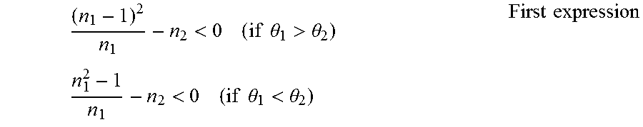
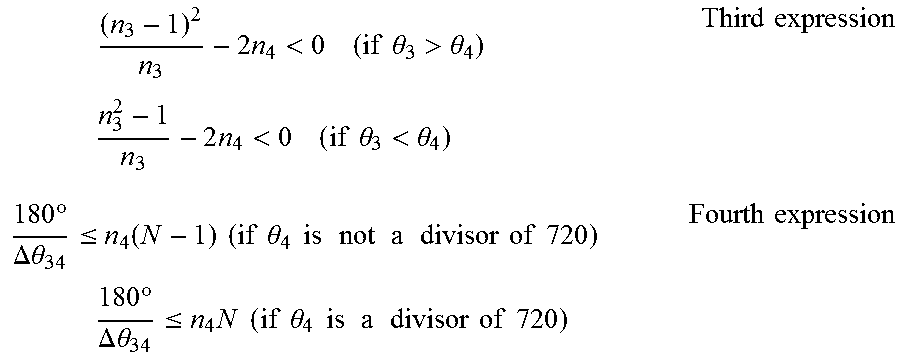

XML
uspto.report is an independent third-party trademark research tool that is not affiliated, endorsed, or sponsored by the United States Patent and Trademark Office (USPTO) or any other governmental organization. The information provided by uspto.report is based on publicly available data at the time of writing and is intended for informational purposes only.
While we strive to provide accurate and up-to-date information, we do not guarantee the accuracy, completeness, reliability, or suitability of the information displayed on this site. The use of this site is at your own risk. Any reliance you place on such information is therefore strictly at your own risk.
All official trademark data, including owner information, should be verified by visiting the official USPTO website at www.uspto.gov. This site is not intended to replace professional legal advice and should not be used as a substitute for consulting with a legal professional who is knowledgeable about trademark law.