Valve Timing Control Device For Internal Combustion Engine And Method For Attaching Valve Timing Control Device
HATSUGAI; Kuninaga ; et al.
U.S. patent application number 16/084688 was filed with the patent office on 2019-03-21 for valve timing control device for internal combustion engine and method for attaching valve timing control device. This patent application is currently assigned to HITACHI AUTOMOTIVE SYSTEMS, LTD.. The applicant listed for this patent is HITACHI AUTOMOTIVE SYSTEMS, LTD.. Invention is credited to Kuninaga HATSUGAI, Yoshinori ICHINOSAWA, Kenji SATO.
| Application Number | 20190085735 16/084688 |
| Document ID | / |
| Family ID | 59850225 |
| Filed Date | 2019-03-21 |


View All Diagrams
| United States Patent Application | 20190085735 |
| Kind Code | A1 |
| HATSUGAI; Kuninaga ; et al. | March 21, 2019 |
VALVE TIMING CONTROL DEVICE FOR INTERNAL COMBUSTION ENGINE AND METHOD FOR ATTACHING VALVE TIMING CONTROL DEVICE
Abstract
It includes: a housing (7) to which a torque is transmitted from a crankshaft; a vane rotor (8) mounted inside the housing and includes a cylindrical rotor (20) fastened to a camshaft (2) by a cam bolt (5); and a groove portion (47) formed at a distal end surface of a tubular part (23) of the rotor and has a lateral surface (47a) in a direction opposite to a direction of fastening of the cam bolt. The lateral surface includes an inside edge (47d) in a radial direction of the rotor, and is inclined in the direction opposite to the direction of fastening of the cam bolt, with respect to a first imaginary plane (S1) containing the inside edge and a rotational axis (O) of the vane rotor. This serves to suppress rotation of the vane rotor during bolting the vane rotor to the camshaft, and suppress deformation due to the suppression of rotation.
| Inventors: | HATSUGAI; Kuninaga; (Atsugi-shi, Kanagawa, JP) ; SATO; Kenji; (Atsugi-shi, Kanagawa, JP) ; ICHINOSAWA; Yoshinori; (Atsugi-shi Kanagawa, JP) | ||||||||||
| Applicant: |
|
||||||||||
|---|---|---|---|---|---|---|---|---|---|---|---|
| Assignee: | HITACHI AUTOMOTIVE SYSTEMS,
LTD. Hitachinaka-shi, Ibaraki JP |
||||||||||
| Family ID: | 59850225 | ||||||||||
| Appl. No.: | 16/084688 | ||||||||||
| Filed: | February 7, 2017 | ||||||||||
| PCT Filed: | February 7, 2017 | ||||||||||
| PCT NO: | PCT/JP2017/004329 | ||||||||||
| 371 Date: | September 13, 2018 |
| Current U.S. Class: | 1/1 |
| Current CPC Class: | F01L 2303/01 20200501; F01L 2303/02 20200501; F01L 2001/3443 20130101; F01L 2001/34479 20130101; F01L 1/053 20130101; F01L 1/3442 20130101; F01L 2250/02 20130101; F01L 2001/34456 20130101; F01L 2001/34483 20130101; F01L 2001/34469 20130101 |
| International Class: | F01L 1/344 20060101 F01L001/344 |
Foreign Application Data
| Date | Code | Application Number |
|---|---|---|
| Mar 15, 2016 | JP | 2016-050822 |
Claims
1. An internal combustion engine valve timing control device comprising: a housing configured to receive a torque transmitted from a crankshaft; a vane rotor mounted inside the housing, and including a rotor, wherein the rotor has a cylindrical shape, and is configured to be fastened to a camshaft by a cam bolt; and a groove portion formed at an end surface of the rotor farther from the camshaft, and including a first lateral surface, wherein the first lateral surface is at a side of the groove portion in a direction opposite to a direction of fastening of the cam bolt; wherein the first lateral surface includes an inside edge and an outside edge in a radial direction of the rotor, wherein the outside edge is in the direction opposite to the direction of fastening of the cam bolt, with respect to a first imaginary plane, wherein the inside edge and a rotational axis of the vane rotor are on the first imaginary plane.
2. The internal combustion engine valve timing control device as claimed in claim 1, wherein: the vane rotor includes a tubular part at an end portion of the vane rotor farther form the camshaft, wherein the tubular part has a cylindrical shape projecting out of the housing; and the groove portion is formed in the tubular part.
3. The internal combustion engine valve timing control device as claimed in claim 2, further comprising a biasing member disposed between the tubular part and the housing, wherein: the biasing member includes a first end portion engaging with the tubular part, and a second end portion engaging with the housing, and is configured to bias the vane rotor in a first rotational direction with respect to the housing; each of a plurality of portions of the tubular part arranged in a circumferential direction of the tubular part is formed with the groove portion; and a portion of the tubular part between specific adjacent two of the groove portions is formed with an engaging groove, wherein the first end portion of the biasing member engages with the engaging groove.
4. The internal combustion engine valve timing control device as claimed in claim 3, wherein the engaging groove is in the direction opposite to the direction of fastening of the cam bolt, with respect to an intermediate position between the specific adjacent two of the groove portions in the circumferential direction of the tubular part.
5. The internal combustion engine valve timing control device as claimed in claim 2, wherein: the groove portion includes a second lateral surface opposite to the first lateral surface; and the second lateral surface includes an inside edge and an outside edge in a radial direction of the tubular part, wherein the outside edge of the second lateral surface is in the direction of fastening of the cam bolt with respect to a second imaginary plane, wherein the inside edge of the second lateral surface and the rotational axis of the vane rotor are on the second imaginary plane.
6. The internal combustion engine valve timing control device as claimed in claim 2, wherein: the groove portion includes a second lateral surface opposite to the first lateral surface; and the second lateral surface includes an inside edge and an outside edge in a radial direction of the tubular part, wherein the outside edge of the second lateral surface is in the direction opposite to the direction of fastening of the cam bolt, with respect to a second imaginary plane, wherein the inside edge of the second lateral surface and the rotational axis of the vane rotor are on the second imaginary plane.
7. The internal combustion engine valve timing control device as claimed in claim 2, wherein the tubular part is formed by sintering integrally with the rotor.
8. An internal combustion engine valve timing control device comprising: a housing configured to receive a torque transmitted from a crankshaft, the housing including an operating chamber formed inside the housing; a vane rotor mounted inside the housing, and including a rotor and a vane, wherein the rotor has a cylindrical shape, and is configured to be fastened to a camshaft by a cam bolt, and wherein the vane separates the operating chamber into a retard operation chamber and an advance operation chamber; an extension part formed at an end portion of the rotor farther form the camshaft, the extension part projecting out of the housing; a biasing member disposed between the extension part and the housing, wherein the biasing member includes a first end portion engaging with the extension part, and a second end portion engaging with the housing, and is configured to bias the vane rotor in a first rotational direction with respect to the housing; and a groove portion formed at a distal end portion of the extension part, and including a first contact surface, wherein the first contact surface is configured to be in contact with a retaining tool for restricting rotation of the rotor during fastening of the cam bolt; wherein the first contact surface is formed such that a vector of load from the retaining tool on the first contact surface during restriction of rotation of the rotor has an inward component in a radial direction of the rotor.
9. An internal combustion engine valve timing control device comprising: a housing configured to receive a torque transmitted from a crankshaft, the housing including an operating chamber formed inside the housing; a vane rotor mounted inside the housing, and including a rotor and a vane, wherein the rotor has a cylindrical shape, and is configured to be fastened to a camshaft by a cam bolt, and wherein the vane separates the operating chamber into a retard operation chamber and an advance operation chamber; and a projecting part formed at an end surface of the rotor farther form the camshaft; wherein the projecting part includes a first lateral surface, wherein the first lateral surface is at a portion of the projecting part in a direction of fastening of the cam bolt; and wherein the first lateral surface includes an inside edge in a radial direction of the rotor, and is inclined in a direction opposite to the direction of fastening of the cam bolt, with respect to a first imaginary plane, wherein the inside edge and a rotational axis of the vane rotor are on the first imaginary plane.
10. A method for attaching an internal combustion engine valve timing control device, wherein the internal combustion engine valve timing control device comprising: a housing configured to receive a torque transmitted from a crankshaft, the housing including an operating chamber formed inside the housing; a vane rotor mounted inside the housing, and including a rotor and a vane, wherein the rotor has a cylindrical shape, and is configured to be fastened to a camshaft by a cam bolt, and wherein the vane separates the operating chamber into a retard operation chamber and an advance operation chamber; and a tool engagement portion formed at an end surface of the rotor farther from the camshaft, and including a first lateral surface facing in a direction of fastening of the cam bolt; wherein the first lateral surface includes an inside edge in a radial direction of the rotor, and is inclined in a direction opposite to the direction of fastening of the cam bolt, with respect to a first imaginary plane, wherein the inside edge and a rotational axis of the vane rotor are on the first imaginary plane; the method comprising: an operation of bringing an end surface of the rotor into contact with an end surface of the camshaft; an operation of engaging a retaining tool into the tool engagement portion, wherein the retaining tool includes an engaging projection and a hole, wherein the engaging projection is configured to engage into the tool engagement portion, and wherein the hole of the retaining tool is configured to receive insertion of a fastening tool for fastening of the cam bolt; and an operation of inserting the fastening tool through the hole of the retaining tool, and fastening the cam bolt by the fastening tool, while restricting rotation of the retaining tool.
Description
TECHNICAL FIELD
[0001] The present invention relates to an internal combustion engine valve timing control device for controlling opening and closing timings of an intake valve set and/or an exhaust valve set variably depending on a state of operation of an internal combustion engine, and a method for attaching the internal combustion engine valve timing control device.
BACKGROUND ART
[0002] A patent document 1 discloses a publicly known conventional internal combustion engine valve timing control device.
[0003] This valve timing control device includes: a cylindrical housing configured to receive a torque transmitted from a crankshaft; and a vane rotor mounted inside the housing, and including a cylindrical rotor, wherein the rotor is configured to be fastened to a camshaft by a cam bolt. The valve timing control device is configured to control opening and closing timings of an intake valve set and/or an exhaust valve set (valve timings) variably by varying a rotational phase of the vane rotor with respect to the housing.
[0004] The valve timing control device further includes a plurality of rectangular groove portions at an inner peripheral wall of a side of the rotor farther from the camshaft. Each groove portion is formed to receive engagement of a projecting portion of a retaining tool for restricting rotation of the rotor during bolt fastening, and includes a contact surface configured to be in contact with the projecting portion, wherein the contact surface is a flat surface extending substantially in a radial direction of the motor.
[0005] Even when a rotating torque is applied to the rotor in a bolt-fastening direction due to sliding contact with a head part of the cam bolt during the bolt fastening, the rotating torque is resisted by each projecting portion of the retaining tool engaged in the corresponding groove portion, thereby suppressing the rotor from being so rotated.
PRIOR ART DOCUMENT(s)
Patent Document(s)
[0006] Patent Document 1: JP H10-317923 A
SUMMARY OF THE INVENTION
Problem(s) to be Solved by the Invention
[0007] While the rotating torque occurring during the bolt fastening is resisted by each projecting portion of the retaining tool as described above, a reaction force is applied to the contact surface of each groove portion of the rotor from the corresponding projecting portion of the retaining tool, wherein the reaction force is equivalent to the rotating torque. This reaction force acts on each contact surface in a normal direction, so that the vane rotor may be pressed outwardly in the radial direction, and may be thereby deformed with increasing diameter, due to the reaction force.
[0008] The present invention is made with attention to the technical problem about the conventional valve timing control device described above, and is targeted for providing a valve timing control device and a method for attaching the valve timing control device, with which when a vane rotor is bolted to a camshaft, it is possible to suppress rotation of the vane rotor, and also suppress deformation of the vane rotor resulting from the suppression of the rotation.
Means for Solving the Problem(s)
[0009] The present invention is characterized by comprising: a housing configured to receive a torque transmitted from a crankshaft; a vane rotor mounted inside the housing, and including a rotor, wherein the rotor has a cylindrical shape, and is configured to be fastened to a camshaft by a cam bolt; and a groove portion formed at an end surface of the rotor farther from the camshaft, and including a first lateral surface, wherein the first lateral surface is at a side of the groove portion in a direction opposite to a direction of fastening of the cam bolt; wherein the first lateral surface includes an inside edge and an outside edge in a radial direction of the rotor, wherein the outside edge is in the direction opposite to the direction of fastening of the cam bolt, with respect to a first imaginary plane, wherein the inside edge and a rotational axis of the vane rotor are on the first imaginary plane.
Effect(s) of the Invention
[0010] According to the present invention, when the vane rotor is bolted to the camshaft, it is possible to suppress rotation of the vane rotor, and also suppress deformation of the vane rotor resulting from the suppression of the rotation.
BRIEF DESCRIPTION OF THE DRAWINGS
[0011] FIG. 1 is a sectional view of whole configuration of a valve timing control device according to a first embodiment of the present invention, taken along a line A-A in FIG. 4.
[0012] FIG. 2 is an exploded perspective view of the valve timing control device.
[0013] FIG. 3 is a perspective view of the valve timing control device.
[0014] FIG. 4 is a front view of the valve timing control device whose valve timing is controlled to a retard side, with a front plate removed.
[0015] FIG. 5 is a front view of the valve timing control device whose valve timing is controlled to an advance side, with the front plate removed.
[0016] FIG. 6 is an enlarged view of a part indicated by B in FIG. 1.
[0017] FIG. 7 is a front view of the valve timing control device.
[0018] FIG. 8 is an enlarged view of a related part including a groove portion of a vane rotor according to the first embodiment.
[0019] FIGS. 9A and 9B are diagrams showing a retaining tool employed for attaching the valve timing control device to a camshaft, where FIG. 9A is a front view of the retaining tool, and FIG. 9B is a side view of the retaining tool.
[0020] FIG. 10 is a diagram illustrating a first operation of a process of attaching the valve timing control device to the camshaft.
[0021] FIG. 11 is a diagram illustrating a second operation and a third operation of the process of attaching the valve timing control device to the camshaft.
[0022] FIG. 12 is a schematic diagram illustrating a torque and its reaction force occurring between the vane rotor and the retaining tool during the third operation.
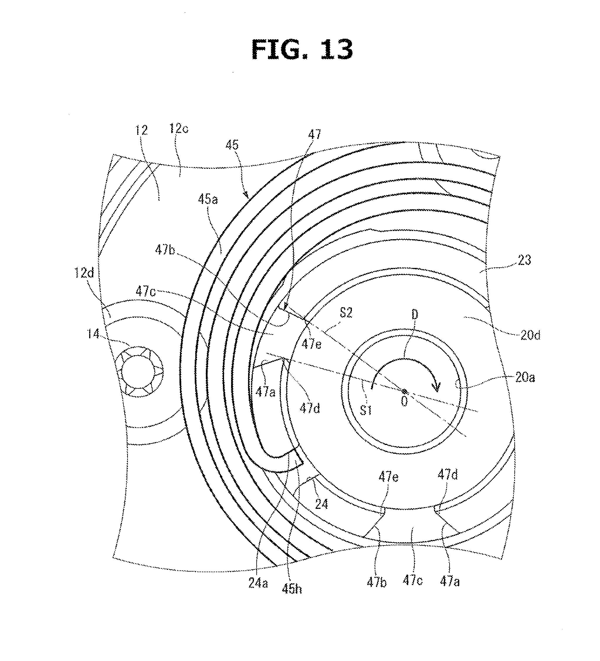
[0023] FIG. 13 is an enlarged view of a related part including a groove portion of a valve timing control device according to a second embodiment of the present invention.
MODE(S) FOR CARRYING OUT THE INVENTION
[0024] The following describes internal combustion engine valve timing control devices according to embodiments of the present invention with reference to the drawings, wherein the present invention is applied to an intake valve side of an internal combustion engine.
First Embodiment
[0025] As shown in FIG. 1, the valve timing control device includes: a sprocket 1 configured to be driven rotationally via a timing chain by a crankshaft not shown; a camshaft 2 configured to rotate with respect to sprocket 1; a phase-varying mechanism 3 disposed between sprocket 1 and camshaft 2, and configured to vary a relative rotational phase between sprocket 1 and camshaft 2; and a hydraulic circuit 4 configured to operate phase-varying mechanism 3 by supplying and draining hydraulic pressures.
[0026] Sprocket 1 is formed integrally with a housing body 11 described below, and includes an outer periphery formed integrally with a plurality of gear parts 1a around which the timing chain is wound.
[0027] Camshaft 2 is rotatably supported via a cam bearing with respect to a cylinder head not shown, and includes a plurality of drive cams for opening intake valves not shown against spring forces of valve springs, wherein each drive cam is formed integrally with an outer peripheral surface of camshaft 2 in a predetermined axial position, and has an egg-shaped cam profile. Camshaft 2 includes a first end portion 2a including a bolt hole 6, wherein bolt hole 6 extends inside of first end portion 2a in its axial direction, and wherein a cam bolt 5 is inserted and screwed in bolt hole 6.
[0028] Cam bolt 5 includes: a head part 5a having a hexagonal shape; and a shaft part 5c formed integrally with an end portion of head part 5a via a seated part 5b having a flange shape, wherein an external thread portion 5d is formed at an outer periphery of a distal end portion of shaft part 5c. During a process of attaching the valve timing control device described below, cam bolt 5 is screwed into bolt hole 6 by rotating the cam bolt 5 in a clockwise direction in FIG. 7 (henceforth referred to as bolt-fastening direction D).
[0029] Bolt hole 6 is formed with an internal thread portion 6a at its bottom side, wherein external thread portion 5d of cam bolt 5 is screwed in internal thread portion 6a of bolt hole 6. A portion of bolt hole 6 closer to its opening side than internal thread portion 6a is formed to have a larger diameter than an outside diameter of shaft part 5c of cam bolt 5, thereby forming an annular oil passage 27c between an inner peripheral surface of bolt hole 6 and an outer peripheral surface of shaft part 5c of cam bolt 5, wherein annular oil passage 27c forms a part of a retard passage 27 described below.
[0030] As shown in FIGS. 1 to 4, phase-varying mechanism 3 includes: a housing 7 disposed at first end portion 2a of camshaft 2, and including an operation chamber therein; and a vane rotor 8 fixed to first end portion 2a of camshaft 2, and mounted rotatably in housing 7; wherein the operation chamber of housing 7 is separated by four shoes, namely, first to fourth shoes 15a-15d described blow, and four vanes 21a-21d described below of vane rotor 8 into four retard hydraulic chambers 9 as retard operation chambers and advance hydraulic chambers 10 as advance operation chambers, wherein first to fourth shoes 15a-15d are formed integrally with an inner peripheral surface of housing body 11.
[0031] Housing 7 includes: housing body 11 having a cylindrical tubular shape including openings at its both axial ends; a front plate 12 enclosing a front end opening of housing body 11; and a rear plate 13 enclosing a rear end opening of housing body 11. Housing body 11, front plate 12, and rear plate 13 are coupled integrally with each other by common fastening of four bolts 14, wherein each bolt 14 passes through a corresponding bolt insertion hole 16 and others as described below.
[0032] Housing body 11 is integrally formed of sintered metal, and is formed integrally with sprocket 1 and the four shoes, namely, first to fourth shoes 15a-15d, wherein sprocket 1 is located substantially at a central portion of an outer periphery of housing body 11 in an axial direction of housing body 11, wherein first to fourth shoes 15a-15d are formed at and project inwardly from an inner peripheral surface of housing body 11, and substantially evenly spaced in a circumferential direction of housing body 11.
[0033] Each shoe 15a-15d is formed to have a substantially trapezoidal shape in its front view, wherein bolt insertion hole 16 is formed to extend though the inside of the shoe 15a-15d in the axial direction, and wherein each bolt 14 is inserted in the corresponding bolt insertion hole 16. Each shoe 15a-15d is formed with a seal groove at its distal end, wherein the seal groove extends in the axial direction of housing body 11, and accommodates a seal member 17, wherein seal member 17 has an U-shape in contact with an outer peripheral surface of a rotor 20 described below.
[0034] The outer peripheral surface of housing body 11 is formed with a positioning groove 11a for positioning the housing body 11 and rear plate 13 in the circumferential direction, wherein positioning groove 11a has a U-shaped cross section, and extends in the axial direction of housing body 11.
[0035] Front plate 12 is formed by press forming of a metal plate to have a disc-shape, and includes a through hole 12a at a central portion of front plate 12, wherein through hole 11a passes through the front plate 12 and has a relatively large diameter such that a tubular part 23 of rotor 20 described blow is inserted in through hole 12a with a predetermined clearance.
[0036] Front plate 12 further includes four bolt holes 12b arranged at its outer peripheral part and substantially evenly spaced in the circumferential direction, wherein each bolt hole 12b extends through the front plate 12, and wherein bolts 14 are inserted in bolt holes 12b. In proximity of an edge of each bolt hole 12b at an outer end surface 12c, a circular seat surface 12d is formed, wherein a head part 14a of each bolt 14 is seated on seat surface 12d. With this configuration, when housing 7 is fastened by each bolt 14, head part 14a of bolt 14 is prevented from projecting forward from outer end surface 12c.
[0037] As shown in FIGS. 1 to 3, a hooded pin 18 is press-fitted and fixed in the axial direction to an outer peripheral part of outer end surface 12c of front plate 12.
[0038] Hooded pin 18 includes a pin body 18a and a hood part 18b, wherein pin body 18a is formed to have a cylindrical shape, and wherein hood part 18b has a disc-shape, and is formed at an end portion of pin body 18a opposite to the end portion press-fitted and fixed.
[0039] A second engaging end portion 45c of a spiral spring 45 described below is wound around the pin body 18a and thereby engaged with pin body 18a.
[0040] Hood part 18b is formed to have a diameter such that hood part 18b covers substantially entire part of an axial end surface of second engaging end portion 45c wound around the pin body 18a, to prevent the second engaging end portion 45c of spiral spring 45 from being released from pin body 18a forward of the device.
[0041] As shown in FIGS. 1 and 2, rear plate 13 is formed of sintered metal material, and includes: a support hole 13a at its central portion, wherein support hole 13a extends through rear plate 13, and supports first end portion 2a of camshaft 2 rotatably; and four internally threaded holes 13b arranged at the outer peripheral part and substantially evenly spaced in the circumferential direction, wherein external thread portion 14c formed at the outer peripheral surface of the distal end portion of shaft part 14b of each bolt 14 is screwed in a corresponding one of internally threaded holes 13b.
[0042] As shown in FIG. 2, a positioning pin 19 is press-fitted and fixed in the outer peripheral part of rear plate 13, wherein positioning pin 19 is engaged in positioning groove 11a of housing body 11 for positioning the housing body 11 and rear plate 13 in the rotational direction.
[0043] Vane rotor 8 is integrally formed of sintered metal material or the like, and as shown in FIGS. 1 to 4, includes rotor 20 and first to fourth vanes 21a-21d, wherein rotor 20 has a cylindrical shape, and is fixed to camshaft 2 by cam bolt 5, and wherein first to fourth vanes 21a-21d are formed at the outer peripheral surface of rotor 20, and substantially evenly spaced in the circumferential direction, and project radially.
[0044] As shown in FIG. 1, rotor 20 includes a bolt hole 20a substantially at its center, wherein bolt hole 20a is formed to extend through rotor 20 in the axial direction, and wherein shaft part 5c of cam bolt 5 is inserted in bolt hole 20a. Between the inner peripheral surface of rotor 20 and the outer peripheral surface of shaft part 5c, an annular passage 27d is defined to form a part of retard passage 27 as described above.
[0045] Rotor 20 includes a circular recess defining a seat surface 20c at a central portion of a front end surface 20b closer to front plate 12, wherein seated part 5b of cam bolt 5 is seated on seat surface 20c.
[0046] Rotor 20 further includes a fitting hole 20d having a circular recess form at a central portion of a rear end surface closer to rear plate 13. Fitting hole 20d is formed to have an inside diameter slightly larger than an outside diameter of a distal end of first end portion 2a of camshaft 2, and is thereby configured to engage with first end portion 2a.
[0047] As shown in FIG. 10, a pin hole 20e is formed in a predetermined position of an outer peripheral part of a bottom surface of fitting hole 20d, wherein pin hole 20e has a circular cross section. An end portion of a pin member 22 having a cylindrical shape is inserted in pin hole 20e. Pin member 22 is arranged between pin hole 20e and a pin groove 2b formed in an outer peripheral part of a distal end surface of first end portion 2a of camshaft 2, thereby positioning the rotor 20 with respect to camshaft 2 in the rotational direction.
[0048] As shown in FIGS. 1 to 3, front end surface 20b of rotor 20 is formed with a tubular part 23 as an extension part configured to extend in the axial direction of rotor 20.
[0049] Tubular part 23 is formed by sintering integrally with rotor 20, and has a substantially cylindrical shape coaxially arranged with the axis of rotor 20. Tubular part 23 includes a distal end portion 23a projecting out of housing 7 through the through hole 12a of front plate 12, and is configured to accommodate the head part 5a of cam bolt 5.
[0050] Tubular part 23 includes an engaging groove 24 configured to engage with first engaging end portion 45b of spiral spring 45 as described below. As shown in FIGS. 2 to 4, engaging groove 24 is located at a predetermined position in the circumferential direction of tubular part 23, and is formed to have a rectangular shape extending from the distal end surface to the proximal end side in the axial direction. Of a pair of surfaces of engaging groove 24 facing each other in the circumferential direction of tubular part 23, a first lateral surface 24a, which engages with first engaging end portion 45b, has an arc shape.
[0051] Tubular part 23 further includes an annular groove 25, wherein annular groove 25 is located substantially at the center of the outer peripheral surface of tubular part 23 in the axial direction, and extends substantially entirely in the circumferential direction, and has a rectangular cross section. Annular groove 25 accommodates an inner peripheral part of spiral spring 45, and thereby suppresses the inner peripheral part of spiral spring 45 from being released from the device.
[0052] As shown in FIGS. 2 and 4, each of first to fourth vanes 21a-21d is disposed between corresponding two of shoes 15a-15d, and has an outer peripheral surface having an arc shape, wherein the outer peripheral surface is formed with a seal groove for accommodating a seal member 26, wherein seal member 26 is U-shaped, and is in sliding contact with the inner peripheral surface of housing body 11.
[0053] Of vanes 21a-21d, the first vane 21a has the largest width, and each of the second to fourth vanes 21b-21d except for first vane 21a has the same width that is smaller than that of first vane 21a.
[0054] When vane rotor 8 is rotated maximally in the counterclockwise direction shown in FIG. 4, the first lateral surface of first vane 21a is brought into contact with the lateral surface of first shoe 15a facing the first vane 21a, so that the rotational position of vane rotor 8 with respect to housing 7 is restricted within the most retarded side. When vane rotor 8 is rotated maximally in the clockwise direction shown in FIG. 4, the second lateral surface of first vane 21a is brought into contact with the lateral surface of second shoe 15b facing the first vane 21a, so that the rotational position of vane rotor 8 is restricted within the most advanced side.
[0055] On the other hand, second to fourth vanes 21b-21d except for first vane 21a are out of contact with the corresponding shoes 8c, 8d facing in the circumferential direction, even when first vane 21a is in contact with first shoe 15a or second shoe 15b. This serves to enhance the precision of contact of first vane 21a with first shoe 15a and second shoe 15b, and further enhance the speed of oil pressure supply to retard hydraulic chambers 9 and advance hydraulic chambers 10, and thereby enhance the response of rotation of vane rotor 8 in normal and reverse directions.
[0056] Each retard hydraulic chamber 9 and each advance hydraulic chamber 10 are hydraulically connected to hydraulic circuit 4 via a retard-side communication hole 9a and an advance-side communication hole 10a respectively, wherein retard-side communication hole 9a and advance-side communication hole 10a are formed inside of rotor 20 and extend radially.
[0057] Hydraulic circuit 4 is configured to selectively supply working oil to retard hydraulic chambers 9 and advance hydraulic chambers 10, drain working oil from retard hydraulic chambers 9 and advance hydraulic chambers 10, and maintain working oil in retard hydraulic chambers 9 and advance hydraulic chambers 10. As shown in FIG. 1, hydraulic circuit 4 generally includes: a retard passage 27 configured to communicate with each retard hydraulic chamber 9 via the retard-side communication hole 9a; an advance oil passage 28 configured to communicate with each advance hydraulic chamber 10 via the advance-side communication hole 10a; a supply passage 29 where working oil flows for supply to retard hydraulic chambers 9 and advance hydraulic chambers 10; a drain passage 30 where working oil flows which is drained from retard hydraulic chambers 9 and advance hydraulic chambers 10; and an electromagnetic switching valve 31 as a hydraulic pressure control valve configured to switch a state of communication of supply passage 29 and drain passage 30 with respect to retard passage 27 and advance passage 28.
[0058] Retard passage 27 includes: a retard passage section 27a configured to communicate with a passage port not shown of electromagnetic switching valve 31; a retard passage hole 27b formed inside of camshaft 2, extending through in the radial direction; annular oil passage 27c formed between the inner peripheral surface of bolt hole 6 and the outer peripheral surface of shaft part 5c of cam bolt 5; and annular passage 27d formed between the inner peripheral surface of rotor 20 and the outer peripheral surface of shaft part 5c, and configured to communicate with retard-side communication holes 9a.
[0059] Advance oil passage 28 includes: an advance passage section 28a configured to communicate with a supply port not shown of electromagnetic switching valve 31; an advance passage hole 28b formed inside camshaft 2, extending through in the radial direction; and four axial oil holes 28c formed to extend in camshaft 2 and rotor 20, wherein each axial oil hole 28c is configured to communicate with the corresponding advance-side communication hole 10a.
[0060] Supply passage 29 includes an upstream end communicating with an oil pan 33 via an oil strainer 32, and a downstream end communicating with a drain port not shown of electromagnetic switching valve 31. Supply passage 29 is provided with an oil pump 34 configured to suck working oil from oil pan 33, and discharge the working oil to electromagnetic switching valve 31.
[0061] Drain passage 30 includes an upstream end communicating with a passage port not shown of electromagnetic switching valve 31, and a downstream end communicating with oil pan 33.
[0062] As shown in FIG. 1, electromagnetic switching valve 31 is a four-port three-position valve, and is controlled by an electronic controller not shown to cause a spool valve not shown to travel longitudinally of a valve body, wherein the spool valve is mounted in the valve body for sliding in the longitudinal direction, and thereby cause supply passage 29 to communicate with one of oil passages 27 (28), and simultaneously cause drain passage 30 to communicate with the other of oil passages 28 (27), or shut off communication among the oil passages 27 to 30.
[0063] The electronic controller includes an internal computer configured to: receive input of informational signals from various sensors not shown, such as a crank angle sensor, an airflow meter, an engine water temperature sensor, a throttle valve opening sensor, and a cam angle sensor for sensing the current rotational phase of camshaft 2; determine the current operating state of the engine; control the spool valve to travel to set positions, by outputting a control pulse current to an electromagnetic coil of electromagnetic switching valve 31, based on the determined current operating state of the engine; and thereby perform a switching control of communication among the passages 27 to 30.
[0064] A lock mechanism 35 is provided between first vane 21a and rear plate 13 for locking the vane rotor 8 in the most advanced position with respect to housing 7.
[0065] As shown in FIGS. 4 and 6, lock mechanism 35 includes: a slide hole 35 formed inside of first vane 21a to extend through in the axial direction; a lock pin 37 slidably mounted in slide hole 36, and configured to travel forward and backward with respect to rear plate 13; a lock hole 38 formed in a substantially central portion of rear plate 13 in the radial direction, and configured to engage with a smaller-diameter portion 37a described below of lock pin 37, and thereby lock the vane rotor 8; and an engaging-releasing mechanism configured to cause and release engagement between smaller-diameter portion 37a of lock pin 37 and lock hole 38, depending on starting state of the engine.
[0066] As shown in FIG. 6, slide hole 36 has an inner peripheral surface having a step shape, including a smaller-diameter hole portion 36a closer to rear plate 13, and a larger-diameter hole portion 36b closer to front plate 12, and a first step portion 36c between smaller-diameter hole portion 36a and larger-diameter hole portion 36b, wherein first step portion 36c has an annular shape.
[0067] Lock pin 37 has an outer peripheral surface having a step shape, and includes: a smaller-diameter portion 37a closer to rear plate 13 (closer to a distal end), slidably mounted in the smaller-diameter hole portion 36a of slide hole 36; and a larger-diameter portion 37b closer to front plate 12, slidably mounted in the larger-diameter hole portion 36b of slide hole 36. Between smaller-diameter portion 37a and larger-diameter portion 37b, a second step portion 37c is formed to have an annular shape. A spring-accommodating recess 37d is formed at a rear end surface of lock pin 37 closer to front plate 12, wherein spring-accommodating recess 37d has a circular recess shape extending inside the lock pin 37 in the axial direction.
[0068] Lock hole 38 is formed in a part of rear plate 13 located in the circumferential direction such that with engagement of lock pin 37, the relative conversion angle of vane rotor 8 with respect to housing 7 is at the most advanced side.
[0069] Lock hole 38 has an inside diameter larger than an outside diameter of smaller-diameter portion 37a of lock pin 37, and has an inner peripheral surface to which a ring member 39 is fitted, wherein smaller-diameter portion 37a of lock pin 37 can be inserted in ring member 39. Ring member 39 is formed of anti-wear material, so that ring member 39 can bear repeated engagement and release of lock pin 37 which accompanies sliding contact of the outer peripheral surface of smaller-diameter portion 37a of lock pin 37 with the inner peripheral surface of lock hole 38.
[0070] The engaging-releasing mechanism includes: a coil spring 40 mounted in compressed state between the inner end surface of front plate 12 and the bottom surface of spring-accommodating recess 37d of lock pin 37, and configured to bias the lock pin 37 in the forward direction; and a first pressure chamber 41 and a second pressure chamber 42 for causing the lock pin 37 to travel in the backward direction, based on hydraulic pressures supplied in first pressure chamber 41 and second pressure chamber 42.
[0071] When vane rotor 8 rotates to the most retarded position with respect to housing 7, the spring force of coil spring 40 causes lock pin 37 to travel in the forward direction, and thereby causes the distal end of smaller-diameter portion 37a of lock pin 37 to engage in lock hole 38, thereby locking the vane rotor 8 with respect to housing 7.
[0072] First pressure chamber 41 is an annular space formed between the first step portion 36c of slide hole 36 and the second step portion 37c of lock pin 37, and communicates via a first oil passage 43 with retard hydraulic chamber 9 defined by first vane 21a, wherein first oil passage 43 is formed to extend through the peripheral wall (see FIG. 4). When working oil is supplied into first pressure chamber 41, the hydraulic pressure of this working oil acts on the second step portion 37c of lock pin 37, and thereby biases lock pin 37 in the backward direction.
[0073] Second pressure chamber 42 is formed in the bottom surface of lock hole 38, having a cylindrical space having a smaller diameter than the smaller-diameter portion 37a of lock pin 37. Second pressure chamber 42 communicates via a second oil passage 44 with advance hydraulic chamber 10 defined by first vane 21a, wherein second oil passage 44 is formed in the peripheral wall to have a thin groove shape (see FIG. 4). When working oil is supplied into second pressure chamber 42, the hydraulic pressure of this working oil acts on the distal end surface of lock pin 37, and thereby biases lock pin 37 in the backward direction.
[0074] As shown in FIGS. 1 to 3 and 7, spiral spring 45 is attached to the outer end surface 12c of front plate 12, wherein spiral spring 45 serves as a biasing member to bias the vane rotor 8 in the advance direction with respect to housing 7.
[0075] Spiral spring 45 includes: a spiral spring body 45a formed by winding a flat rectangular wire, which has a substantially rectangular cross-section, substantially in a plane, such that surfaces in the longitudinal direction face each other, the spiral spring body 45a having a shape whose diameter gradually increases from its inside peripheral part to its outside peripheral part; first engaging end portion 45b formed to have a curved shape, by bending a first end portion of the inside peripheral part of spiral spring body 45a inwardly in the radial direction; and second engaging end portion 45c curved to have a semicircular hook shape, by bending a second end portion of the outside peripheral part of spiral spring body 45a outwardly in the radial direction.
[0076] An innermost peripheral part of spiral spring body 45a closer to first engaging end portion 45b is accommodated in annular groove 25 formed in tubular part 23, whereas an outermost peripheral part of spiral spring body 45a closer to second engaging end portion 45c is supported by a support pin 46 (see FIG. 3) press-fitted and fixed to outer end surface 12c of front plate 12. Support pin 46 thus supports the outermost peripheral part of spiral spring 45 and thereby allows spiral spring 45 to perform a stable biasing action between housing 7 and vane rotor 8, and when spiral spring 45 is deformed with decreasing diameter, serves to enhance a torque occurring between second engaging end portion 45c and a portion of spiral spring 45 in contact with support pin 46.
[0077] First engaging end portion 45b is engaged in engaging groove 24 of tubular part 23, and engaged with and fixed to first lateral surface 24a of engaging groove 24, whereas second engaging end portion 45c is engaged with and fixed to an outer peripheral surface of pin body 18a of hooded pin 18 provided at outer end surface 12c of front plate 12.
[0078] This spiral spring 45 biases vane rotor 8 in the advance direction with respect to housing 7 as described above. This biasing force is not so large to actively rotate vane rotor 8 in the advance direction, but is set to be in balance with a negative component of an alternating torque occurring in camshaft 2 while the engine is operating, wherein the negative component causes vane rotor 8 to move toward the retard side.
[0079] Namely, the phase conversion of vane rotor 8 is mainly based on the hydraulic pressures supplied to retard hydraulic chambers 9 and advance hydraulic chambers 10, wherein the biasing effect of spiral spring 45 serves to assist holding of the phase of vane rotor 8.
[0080] As shown in FIGS. 2 to 4, 7, and 8, tubular part 23 includes three groove portions 47 evenly spaced in the circumferential direction, wherein each groove portion 47 has a U-shape, and serves as a tool engagement portion in which an engaging projection 54 of a retaining tool 52 described below engages during bolt fastening.
[0081] As shown in FIG. 7, each groove portion 47 includes: a first lateral surface 47a as a first contact surface at a side in a direction opposite to the bolt-fastening direction D; a second lateral surface 47b as a second contact surface opposite to first lateral surface 47a; and a bottom surface 47c having an arc shape connected between the first lateral surface 47a and second lateral surface 47b.
[0082] As shown in FIG. 8, first lateral surface 47a is a flat surface including an inside edge 47d in a radial direction of tubular part 23 (rotor 20), and is inclined in the direction opposite to the bolt-fastening direction D, with respect to a first imaginary plane S1, wherein the inside edge 47d and a rotational axis O of vane rotor 8 are on the first imaginary plane S1. In other words, first lateral surface 47a includes inside edge 47d and an outside edge 47f in the radial direction of tubular part 23 (rotor 20), wherein the outside edge 47f is in the direction opposite to the bolt-fastening direction D with respect to the first imaginary plane S1, wherein the inside edge 47d and the rotational axis O of vane rotor 8 are on the first imaginary plane S1.
[0083] On the other hand, second lateral surface 47b is a flat surface including an inside edge 47e in a radial direction of tubular part 23 (rotor 20), and is inclined in the bolt-fastening direction D, with respect to a second imaginary plane S2, wherein the inside edge 47e and the rotational axis O of vane rotor 8 are on the second imaginary plane S2. In other words, second lateral surface 47b includes inside edge 47e and an outside edge 47g in the radial direction of tubular part 23 (rotor 20), wherein the outside edge 47g is in the bolt-fastening direction with respect to the second imaginary plane S2, wherein the inside edge 47e and the rotational axis O of vane rotor 8 are on the second imaginary plane S2.
[0084] Namely, each groove portion 47 has a V-shape in its front view, wherein the groove width of groove portion 47 in the circumferential direction of tubular part 23 gradually increases from the inner peripheral part of tubular part 23 to the outer peripheral part of tubular part 23.
[0085] As specifically shown in FIG. 10, each groove portion 47 has a groove depth that is slightly smaller than the axial length of tubular part 23, wherein bottom surface 47c of groove portion 47 is located slightly ahead of front end surface 20b of rotor 20 in the device forward direction, namely, located closer to distal end portion 23a of tubular part 23 than front end surface 20b of rotor 20.
[0086] The position of engaging groove 24 in the circumferential direction of tubular part 23 is determined depending on positional relationship with groove portions 47.
[0087] Specifically, as shown in FIG. 8, engaging groove 24 is arranged between specific adjacent two of groove portions 47 in the circumferential direction of tubular part 23, wherein groove portion 47 is arranged in an arrangement position P1 slightly in the direction opposite to the bolt-fastening direction D, with respect to an intermediate position P0 between the specific adjacent two of groove portions 47.
Method for Attaching Valve Timing Control Device
[0088] As described above, the valve timing control device is attached to camshaft 2 by fastening by cam bolt 5. This fastening operation employs a hexagonal wrench 51 (see FIG. 11) and a retaining tool 52, wherein hexagonal wrench 51 is a common bolt fastening tool including a fitting portion 51a fitted with the hexagonal head part 5a of cam bolt 5, and wherein retaining tool 52 is used to retain vane rotor 8 while the fastening operation is performed by hexagonal wrench 51.
[0089] As shown in FIGS. 9A and 9B, retaining tool 52 is integrally formed of metal material, including: a base portion 53 having a cylindrical shape; three engaging projections 54 formed at an axial end surface of base portion 53, projecting therefrom; and a grip portion 55 extending from an outer peripheral surface of base portion 53.
[0090] Base portion 53 has a diameter substantially equal to the diameter of tubular part 23 of vane rotor 8, and includes an insertion hole 53a, wherein insertion hole 53a extends through base portion 53, and wherein hexagonal wrench 51 can be inserted through insertion hole 53a and engaged with head part 5a of cam bolt 5.
[0091] As shown in FIG. 9A, engaging projections 54 are spaced substantially evenly in the circumferential direction of base portion 53, and each engaging projection 54 has a shape fitted with the corresponding groove portion 47 of tubular part 23, and is configured to engage in the corresponding groove portion 47.
[0092] Namely, each engaging projection 54 is sector-shaped in its front view, and includes: a first engaging surface 54a facing the first lateral surface 47a of groove portion 47 when engaging projection 54 engages in groove portion 47; and a second engaging surface 54b facing the second lateral surface 47b of groove portion 47 when engaging projection 54 engages in groove portion 47.
[0093] The following describes operations of the process of attaching the valve timing control device to camshaft 2 with reference to FIGS. 10 to 12.
[0094] FIG. 10 shows a first operation of inserting the valve timing control device, where the components except for spiral spring 45 are assembled proactively, into camshaft 2 in the axial direction, and engaging the fitting hole 20d of rotor 20 with the first end portion 2a of camshaft 2.
[0095] In this operation, vane rotor 8 is restricted in the most retarded position with respect to housing 7 by engagement between lock pin 37 and lock hole 38, and is positioned in the circumferential direction with respect to camshaft 2 by pin member 22.
[0096] The foregoing is followed by a second operation of inserting the cam bolt 5 into bolt hole 6 of camshaft 2, and thereafter causing the engaging projections 54 of retaining tool 52 to engage into groove portions 47 of tubular part 23 in the axial direction of cam bolt 5, as shown in FIG. 11.
[0097] The foregoing is followed by a third operation of: inserting the fitting portion 51a at the distal end of hexagonal wrench 51 into insertion hole 53a of retaining tool 52 so that the fitting portion 51a is fitted with head part 5a of cam bolt 5; and thereafter rotating the hexagonal wrench 51 in the bolt-fastening direction D while grasping the grip portion 55 of retaining tool 52.
[0098] In this operation, as shown in FIG. 12, vane rotor 8 is brought into contact with seated part 5b of cam bolt 5 being rotated, and is thereby applied with a rotating effort in the bolt-fastening direction D via seated part 5b. However, the first engaging surface 54a of each engaging projection 54 of retaining tool 52 fixed by grasping is in contact with first lateral surface 47a of the corresponding groove portion 47, thereby suppressing rotation of vane rotor 8. Accordingly, the outer peripheral surface of pin member 22 inserted between vane rotor 8 and camshaft 2, and the outer peripheral surface of lock pin 37 engaged in lock hole 38, are applied with no large shear force, thereby suppressing deformation of pin member 22 and lock pin 37.
[0099] Then, external thread portion 5d of cam bolt 5 is screwed completely to internal thread portion 6a of bolt hole 6. This is followed by a fourth operation of attaching the spiral spring 45 to outer end surface 12c of front plate 12, thus completing the process of attaching the valve timing control device to camshaft 2.
[0100] A process of detaching the valve timing control device from camshaft 2 is implemented by reversing the operations of the attaching process described above. In this process, the contact of second engaging surface 54b of each engaging projection 54 of retaining tool 52 with second lateral surface 47a of the corresponding groove portion 47, serves to suppress vane rotor 8 from being rotated in the direction of releasing the cam bolt 5 (in the direction opposite to the bolt-fastening direction D). This serves to suppress deformation of pin member 22 and lock pin 37 during the detaching process of the valve timing control device.
Operation and Effects of Present Embodiment
[0101] In the valve timing control device according to the present embodiment configured as described above, the control current is suitably controlled by the electronic controller not shown to flow through the coil of electromagnetic switching valve 31, depending on the operation state of the engine, thereby switching the state of communication among the passages 27 to 30. This switching of the state of communication varies the relationship in hydraulic pressure between each retard hydraulic chamber 9 and advance hydraulic chamber 10, and thereby causes the rotational phase of vane rotor 8 with respect to housing 7 (sprocket 1) to vary to the most retarded state shown in FIG. 4 or the most advanced state shown in FIG. 5, thereby varying the valve timing of the engine.
[0102] Furthermore, in the valve timing control device according to the present embodiment, when the engine is operating, the valve timing of the engine can be maintained at a desired phase by shutting off communication among the passages 27 to 30 by electromagnetic switching valve 31, and thereby maintaining the condition where working oil is supplied in retard hydraulic chambers 9 and advance hydraulic chambers 10.
[0103] According to the present embodiment, the provision of spiral spring 45 for biasing the vane rotor 8 in the advance direction with respect to housing 7, allows to easily balance the spring force of spiral spring 45 with the negative component of the alternating torque occurring in camshaft 2 while the engine is operating, and thereby maintain the valve timing easily and precisely.
[0104] According to the present embodiment, the employment of spiral spring 45 as a biasing member for holding the phase, serves to shorten the size in the axial direction, and thereby allow the device to be made compact, as compared to a case where a torsion spring or the like is employed.
[0105] According to the present embodiment, deformation of vane rotor 8 is suppressed during the process of attaching the valve timing control device to camshaft 2.
[0106] In the valve timing control device according to the present embodiment where engaging projections 54 of retaining tool 52 are engaged in groove portions 47 of vane rotor 8, and rotation of vane rotor 8 is suppressed during bolt fastening, the torque F1 of vane rotor 8 is resisted by first engaging surface 54a of each engaging projection 54, while the reaction force (load) F2 equivalent to the torque F1 simultaneously acts on first lateral surface 47a of each groove portion 47, as shown in FIG. 12.
[0107] In this situation, if the reaction force F2 has an outward vector component in the radial direction of vane rotor 8, vane rotor 8 may be deformed outwardly with increasing diameter by the reaction force F2. In contrast, according to the present embodiment, the feature that first lateral surface 47a of each groove portion 47 is inclined in the direction opposite to the bolt-fastening direction D, with respect to the first imaginary plane S1, causes the reaction force F2 to have an inward vector component F2rad in the radial direction of vane rotor 8, which acts on each first lateral surface 47a to press the vane rotor 8 inwardly.
[0108] This serves to suppress vane rotor 8 from being pressed outwardly by the reaction force F2 during bolt fastening, and thereby suppress vane rotor 8 from being deformed with increasing diameter.
[0109] In this way, the present embodiment serves to suppress rotation of vane rotor 8 during bolt fastening of vane rotor 8 to camshaft 2, and also suppress deformation of vane rotor 8 resulting from the suppression of rotation of vane rotor 8.
[0110] The advantageous effects described above are significant, especially for the valve timing control device according to the present embodiment where groove portions 47 are formed in tubular part 23 of vane rotor 8, which has a relatively thin wall (lower rigidity), and is used for engagement of spiral spring 45.
[0111] If there is a concern about the strength of tubular part 23, it is conceivable to increase the thickness of tubular part 23 and thereby enhance the strength of tubular part 23, or implement the tubular part 23 by a separate member having a higher rigidity. However, the former may cause an increase of the weight of the device, whereas the latter may cause the process of assembling to be complicated by an increase of the number of components.
[0112] In contrast, the present embodiment where rotor 20 and tubular part 23 are formed integrally, and the reaction force F2 is resisted with adjustment of the direction of action of the reaction force F2, serves to suppress deformation of tubular part 23 resulting from the reaction force F2, without increasing the weight of the device and without increasing the number of components.
[0113] Furthermore, the present embodiment where engaging groove 24, with which first engaging end portion 45b of spiral spring 45 is engaged, is located at a position in the circumferential direction so as not to interfere with groove portions 47, does not cause a problem where engaging groove 24 interferes with retaining tool 52, and does not adversely affect the process of bolt fastening.
[0114] Furthermore, in the present embodiment, arrangement position P1 of engaging groove 24 is in the direction opposite to the bolt-fastening direction D, with respect to the intermediate position P0 between the specific two groove portions 47, 47 in the circumferential direction of tubular part 23. Accordingly, as shown in FIG. 12, among wall portions 23b, 23c between the specific groove portions 47, 47 of tubular part 23, the wall portion 23b receiving the reaction force F2 from engaging projection 54 of retaining tool 52 (at a side in the bolt-fastening direction D) has a larger cross-section. This serves to suppress the strength of vane rotor 8 against the reaction force F2 from being lowered. Therefore, even with provision of engaging groove 24, it is possible to sufficiently resist the reaction force F2.
[0115] The feature of the present embodiment that second lateral surface 47b of each groove portion 47 is formed as a flat surface inclined in the bolt-fastening direction D with respect to the second imaginary plane S2, results in that when the valve timing control device becomes failed, and is detached from camshaft 2, a reaction force F4 of a torque F3 occurring in vane rotor 8 due to releasing action of cam bolt 5 has an inward vector component F4rad in the radial direction of vane rotor 8. This serves to cause the reaction force F4 to be applied to tubular part 23 inwardly, and thereby suppress vane rotor 8 from being deformed with increasing diameter, when cam bolt 5 is detached.
[0116] The feature of the present embodiment that each groove portion 47 has the groove depth such that the bottom surface 47c is closer to the distal end portion 23a of tubular part 23 than front end surface 20b of rotor 20, serves to allow each groove portion 47 to be easily formed, because each groove portion 47 is out of the inside of rotor 20.
[0117] The feature of the present embodiment that bottom surface 47c of each groove portion 47 is arc-shaped, serves to suppress stress concentration to a specific part of tubular part 23 when the reaction force F2 is applied to tubular part 23 during bolt fastening, and thereby further suppress deformation of tubular part 23.
Second Embodiment
[0118] FIG. 13 shows a second embodiment of the present invention, which is basically configured as the first embodiment, but is modified in the shape of second lateral surface 47b of each groove portion 47.
[0119] Basically, the valve timing control device is not repeatedly attached to nor detached from camshaft 2, but is maintained attached to camshaft 2 for a long time period once the valve timing control device gets attached to camshaft 2. In general, the torque F3 occurring in vane rotor 8 when cam bolt 5 is released is smaller than the torque F1 occurring in vane rotor 8 during bolt fastening.
[0120] In view of the foregoing, the present embodiment is configured such that second lateral surface 47b of each groove portion 47 is formed as a flat surface inclined in the direction opposite to the bolt-fastening direction D, with respect to the second imaginary plane S2.
[0121] This feature serves to reduce the groove width (the length in the circumferential direction of tubular part 23) of each groove portion 47 smaller than that in the valve timing control device of the first embodiment, and thereby allow the cross-sectional area of tubular part 23 to be increased, and thereby enhance the strength of tubular part 23, although it is slightly possible that vane rotor 8 is deformed with increasing diameter when cam bolt 5 is released. This serves to further suppress deformation of vane rotor 8 during bolt fastening.
[0122] Other operation and effects are the same as in the first embodiment.
[0123] The present invention is not limited to the specific configurations of the embodiments described above, but may be modified without deviating from the substance of the present invention.
[0124] For example, although each of the embodiments is configured such that each groove portion 47 is formed in tubular part 23 of rotor 20, each groove portion 47 may be formed in front end surface 20b of rotor 20 with tubular part 23 removed.
[0125] In each of the embodiments, rotation of vane rotor 8 is suppressed by forming the tubular part 23 at front end surface 20b of rotor 20, and engaging each engaging projection 54 of retaining tool 52 in the corresponding groove portion 47 formed in the distal end surface of tubular part 23. However, rotation of vane rotor 8 may be suppressed by a configuration that tubular part 23 is removed, and a plurality of projecting parts are formed at front end surface 20b of rotor 20, and each engaging projection 54 of retaining tool 52 is engaged between the projecting parts, and a first lateral surface of each projecting part at a side in the bolt-fastening direction D is engaged with first engaging surface 54a of each engaging projection 54.
[0126] The internal combustion engine valve timing control device and the method for attaching the internal combustion engine valve timing control device according to the embodiments described above may be exemplified as follows.
[0127] According to one aspect, an internal combustion engine valve timing control device includes: a housing configured to receive a torque transmitted from a crankshaft; a vane rotor mounted inside the housing, and including a rotor, wherein the rotor has a cylindrical shape, and is configured to be fastened to a camshaft by a cam bolt; and a groove portion formed at an end surface of the rotor farther from the camshaft, and including a first lateral surface, wherein the first lateral surface is at a side of the groove portion in a direction opposite to a direction of fastening of the cam bolt; wherein the first lateral surface includes an inside edge and an outside edge in a radial direction of the rotor, wherein the outside edge is in the direction opposite to the direction of fastening of the cam bolt, with respect to a first imaginary plane, wherein the inside edge and a rotational axis of the vane rotor are on the first imaginary plane.
[0128] According to a preferable aspect, the internal combustion engine valve timing control device is configured such that: the vane rotor includes a tubular part at an end portion of the vane rotor farther form the camshaft, wherein the tubular part has a cylindrical shape projecting out of the housing; and the groove portion is formed in the tubular part.
[0129] According to another preferable aspect, the internal combustion engine valve timing control device according to one of the foregoing aspects further includes a biasing member disposed between the tubular part and the housing, wherein: the biasing member includes a first end portion engaging with the tubular part, and a second end portion engaging with the housing, and is configured to bias the vane rotor in a first rotational direction with respect to the housing; each of a plurality of portions of the tubular part arranged in a circumferential direction of the tubular part is formed with the groove portion; and a portion of the tubular part between specific adjacent two of the groove portions is formed with an engaging groove, wherein the first end portion of the biasing member engages with the engaging groove.
[0130] According to a further preferable aspect, the internal combustion engine valve timing control device according to one of the foregoing aspects is configured such that the engaging groove is in the direction opposite to the direction of fastening of the cam bolt, with respect to an intermediate position between the specific adjacent two of the groove portions in the circumferential direction of the tubular part.
[0131] According to a further preferable aspect, the internal combustion engine valve timing control device according to one of the foregoing aspects is configured such that: the groove portion includes a second lateral surface opposite to the first lateral surface; and the second lateral surface includes an inside edge and an outside edge in a radial direction of the tubular part, wherein the outside edge of the second lateral surface is in the direction of fastening of the cam bolt with respect to a second imaginary plane, wherein the inside edge of the second lateral surface and the rotational axis of the vane rotor are on the second imaginary plane.
[0132] According to a further preferable aspect, the internal combustion engine valve timing control device according to one of the foregoing aspects is configured such that: the groove portion includes a second lateral surface opposite to the first lateral surface; and the second lateral surface includes an inside edge and an outside edge in a radial direction of the tubular part, wherein the outside edge of the second lateral surface is in the direction opposite to the direction of fastening of the cam bolt, with respect to a second imaginary plane, wherein the inside edge of the second lateral surface and the rotational axis of the vane rotor are on the second imaginary plane.
[0133] According to a further preferable aspect, the internal combustion engine valve timing control device according to one of the foregoing aspects is configured such that the groove portion includes a bottom surface closer to the tubular part than the end surface of the rotor farther from the camshaft.
[0134] According to a further preferable aspect, the internal combustion engine valve timing control device according to one of the foregoing aspects is configured such that: the bottom surface of the groove portion is arc-shaped.
[0135] According to a further preferable aspect, the internal combustion engine valve timing control device according to one of the foregoing aspects is configured such that the biasing member is a spiral spring.
[0136] According to a further preferable aspect, the internal combustion engine valve timing control device according to one of the foregoing aspects is configured such that the tubular part is formed by sintering integrally with the rotor.
[0137] In another viewpoint, an internal combustion engine valve timing control device includes: a housing configured to receive a torque transmitted from a crankshaft, the housing including an operating chamber formed inside the housing; a vane rotor mounted inside the housing, and including a rotor and a vane, wherein the rotor has a cylindrical shape, and is configured to be fastened to a camshaft by a cam bolt, and wherein the vane separates the operating chamber into a retard operation chamber and an advance operation chamber; an extension part formed at an end portion of the rotor farther form the camshaft, the extension part projecting out of the housing; a biasing member disposed between the extension part and the housing, wherein the biasing member includes a first end portion engaging with the extension part, and a second end portion engaging with the housing, and is configured to bias the vane rotor in a first rotational direction with respect to the housing; and a groove portion formed at a distal end portion of the extension part, and including a first contact surface, wherein the first contact surface is configured to be in contact with a retaining tool for restricting rotation of the rotor during fastening of the cam bolt; wherein the first contact surface is formed such that a vector of load from the retaining tool on the first contact surface during restriction of rotation of the rotor has an inward component in a radial direction of the rotor.
[0138] According to a preferable aspect, the internal combustion engine valve timing control device based on the other viewpoint is configured such that: each of a plurality of portions of the extension part arranged in a circumferential direction of the extension part is formed with the groove portion; and a portion of the extension part between specific adjacent two of the groove portions is formed with an engaging groove, wherein the first end portion of the biasing member engages with the engaging groove.
[0139] According to another preferable aspect, the internal combustion engine valve timing control device according to one of the foregoing aspects based on the other viewpoint is configured such that the engaging groove is in the direction opposite to the direction of fastening of the cam bolt, with respect to an intermediate position between the specific adjacent two of the groove portions in the circumferential direction of the extension part.
[0140] According to a further preferable aspect, the internal combustion engine valve timing control device according to one of the foregoing aspects based on the other viewpoint is configured such that the extension part is formed by sintering integrally with the rotor.
[0141] In a further viewpoint, an internal combustion engine valve timing control device includes: a housing configured to receive a torque transmitted from a crankshaft, the housing including an operating chamber formed inside the housing; a vane rotor mounted inside the housing, and including a rotor and a vane, wherein the rotor has a cylindrical shape, and is configured to be fastened to a camshaft by a cam bolt, and wherein the vane separates the operating chamber into a retard operation chamber and an advance operation chamber; and a projecting part formed at an end surface of the rotor farther form the camshaft; wherein the projecting part includes a first lateral surface, wherein the first lateral surface is at a portion of the projecting part in a direction of fastening of the cam bolt; and wherein the first lateral surface includes an inside edge in a radial direction of the rotor, and is inclined in a direction opposite to the direction of fastening of the cam bolt, with respect to a first imaginary plane, wherein the inside edge and a rotational axis of the vane rotor are on the first imaginary plane.
[0142] In a still further viewpoint, a method for attaching an internal combustion engine valve timing control device, wherein the internal combustion engine valve timing control device including: a housing configured to receive a torque transmitted from a crankshaft, the housing including an operating chamber formed inside the housing; a vane rotor mounted inside the housing, and including a rotor and a vane, wherein the rotor has a cylindrical shape, and is configured to be fastened to a camshaft by a cam bolt, and wherein the vane separates the operating chamber into a retard operation chamber and an advance operation chamber; and a tool engagement portion formed at an end surface of the rotor farther from the camshaft, and including a first lateral surface facing in a direction of fastening of the cam bolt; wherein the first lateral surface includes an inside edge in a radial direction of the rotor, and is inclined in a direction opposite to the direction of fastening of the cam bolt, with respect to a first imaginary plane, wherein the inside edge and a rotational axis of the vane rotor are on the first imaginary plane; the method includes: an operation of bringing an end surface of the rotor into contact with an end surface of the camshaft; an operation of engaging a retaining tool into the tool engagement portion, wherein the retaining tool includes an engaging projection and a hole, wherein the engaging projection is configured to engage into the tool engagement portion, and wherein the hole of the retaining tool is configured to receive insertion of a fastening tool for fastening of the cam bolt; and an operation of inserting the fastening tool through the hole of the retaining tool, and fastening the cam bolt by the fastening tool, while restricting rotation of the retaining tool.
* * * * *
D00000
D00001
D00002
D00003
D00004
D00005
D00006
D00007
D00008
D00009
D00010
D00011
D00012

D00013
XML
uspto.report is an independent third-party trademark research tool that is not affiliated, endorsed, or sponsored by the United States Patent and Trademark Office (USPTO) or any other governmental organization. The information provided by uspto.report is based on publicly available data at the time of writing and is intended for informational purposes only.
While we strive to provide accurate and up-to-date information, we do not guarantee the accuracy, completeness, reliability, or suitability of the information displayed on this site. The use of this site is at your own risk. Any reliance you place on such information is therefore strictly at your own risk.
All official trademark data, including owner information, should be verified by visiting the official USPTO website at www.uspto.gov. This site is not intended to replace professional legal advice and should not be used as a substitute for consulting with a legal professional who is knowledgeable about trademark law.