Modular Fence Post Assembly
McKinney; Jimmie
U.S. patent application number 15/707667 was filed with the patent office on 2019-03-21 for modular fence post assembly. The applicant listed for this patent is Jimmie McKinney. Invention is credited to Jimmie McKinney.
| Application Number | 20190085589 15/707667 |
| Document ID | / |
| Family ID | 65719955 |
| Filed Date | 2019-03-21 |


| United States Patent Application | 20190085589 |
| Kind Code | A1 |
| McKinney; Jimmie | March 21, 2019 |
MODULAR FENCE POST ASSEMBLY
Abstract
A modular fence post assembly for forming a barrier on a sloped surface includes a plurality of fence posts. Each of the fence posts has a top end, a bottom end and a perimeter wall that is attached to and extends between the top and bottom ends. The fence posts are positioned adjacent to each other and lie in the same plane with respect to each other. The fence posts each have a vertically orientated longitudinal axis and plurality of couplers. Each of the fence posts is coupled to an adjacent one of the fence posts by at least one of the couplers such that a continuous wall is defined including each of the fence posts. The couplers allow adjacent ones of the fence posts to be vertically adjusted relative to each.
| Inventors: | McKinney; Jimmie; (Fredericksburg, VA) | ||||||||||
| Applicant: |
|
||||||||||
|---|---|---|---|---|---|---|---|---|---|---|---|
| Family ID: | 65719955 | ||||||||||
| Appl. No.: | 15/707667 | ||||||||||
| Filed: | September 18, 2017 |
| Current U.S. Class: | 1/1 |
| Current CPC Class: | E04H 17/1426 20130101; E04H 17/22 20130101; E04H 2017/1491 20130101; E04H 17/1439 20130101 |
| International Class: | E04H 17/14 20060101 E04H017/14; E04H 17/22 20060101 E04H017/22 |
Claims
1. A fence assembly configured to form a barrier on a sloped surface, said fence assembly comprising: a plurality of fence posts, each of said fence posts having a top end, a bottom end and a perimeter wall being attached to and extending between said top and bottom ends; said fence posts being positioned adjacent to each other and lying in a same plane with respect to each other, said fence posts each having a vertically orientated longitudinal axis; and a plurality of couplers, each of said fence posts being coupled to an adjacent one of said fence posts by at least one of said couplers such that a continuous wall is defined including each of said fence posts, said couplers allowing adjacent ones of said fence posts to be vertically adjusted relative to each other while retaining said longitudinal axes in a vertical orientation.
2. The fence assembly configured to form a barrier on a sloped surface according to claim 1, said fence assembly comprising: wherein said bottom end of each of said fence posts is open and defines a receiving space; and a plurality of ground anchors, each of said ground anchors having a first end and a second end, each of said first ends being removably extendable into said receiving space, each of said second ends being extendable into a ground surface, each of said second ends being configured for piercing and anchoring said fence post in a surface.
3. The fence assembly configured to form a barrier on a sloped surface according to claim 2, wherein each of said second ends is pointed.
4. The fence assembly configured to form a barrier on a sloped surface according to claim 1, wherein each of said couplers comprises an accordion hinge.
5. The fence assembly configured to form a barrier on a sloped surface according to claim 4, wherein each of said fence posts is coupled to the next adjacent one of said fence posts with two of said couplers.
6. The fence assembly configured to form a barrier on a sloped surface according to claim 1, wherein each of said fence posts is coupled to the next adjacent one of said fence posts with two of said couplers.
7. The fence assembly configured to form a barrier on a sloped surface according to claim 1, wherein each of said top ends comprises a planar surface configured to be struck by a hammer;
8. A fence assembly configured to form a barrier on a sloped surface, said fence assembly comprising: a plurality of fence posts, each of said fence posts having a top end, a bottom end and a perimeter wall being attached to and extending between said top and bottom ends, said bottom end being open and defining a receiving space, each of said top ends comprising a planar surface configured to be struck by a hammer each of said fence posts having a height between 30.0 inches and 50.0 inches; said fence posts being positioned adjacent to each other and lying in a same plane with respect to each other, said fence posts each having a vertically orientated longitudinal axis; a plurality of couplers, each of said fence posts being coupled to an adjacent one of said fence posts by at least one of said couplers such that a continuous wall is defined including each of said fence posts, said couplers allowing adjacent ones of said fence posts to be vertically adjusted relative to each other while retaining said longitudinal axes in a vertical orientation, each of said couplers comprising an accordion hinge, each of said fence posts being coupled to the next adjacent one of said fence posts with two of said couplers, each of said couplers being positioned between 4.0 inches and 12.0 inches from said top ends of said fence posts; and a plurality of ground anchors, each of said ground anchors having a first end and a second end, each of said first ends being removably extendable into said receiving space, each of said second ends being extendable into a ground surface, each of said second ends being configured for piercing and anchoring said fence post in a surface, each of said second ends being pointed, each of said ground anchors extending outwardly from said bottom ends a distance equal to at least 8.0 inches.
Description
CROSS-REFERENCE TO RELATED APPLICATIONS
[0001] Not Applicable
STATEMENT REGARDING FEDERALLY SPONSORED RESEARCH OR DEVELOPMENT
[0002] Not Applicable
THE NAMES OF THE PARTIES TO A JOINT RESEARCH AGREEMENT
[0003] Not Applicable
INCORPORATION-BY-REFERENCE OF MATERIAL SUBMITTED ON A COMPACT DISC OR AS A TEXT FILE VIA THE OFFICE ELECTRONIC FILING SYSTEM
[0004] Not Applicable
STATEMENT REGARDING PRIOR DISCLOSURES BY THE INVENTOR OR JOINT INVENTOR
[0005] Not Applicable
BACKGROUND OF THE INVENTION
(1) Field of the Invention
(2) Description of Related Art Including Information Disclosed under 37 CFR 1.97 and 1.98.
[0006] The disclosure and prior art relates to modular fence post devices and more particularly pertains to a new modular fence post device for forming a barrier on a sloped surface.
BRIEF SUMMARY OF THE INVENTION
[0007] An embodiment of the disclosure meets the needs presented above by generally comprising a plurality of fence posts. Each of the fence posts has a top end, a bottom end and a perimeter wall that is attached to and extends between the top and bottom ends. The fence posts are positioned adjacent to each other and lie in the same plane with respect to each other. The fence posts each have a vertically orientated longitudinal axis and plurality of couplers. Each of the fence posts is coupled to an adjacent one of the fence posts by at least one of the couplers such that a continuous wall is defined including each of the fence posts. The couplers allow adjacent ones of the fence posts to be vertically adjusted relative to each.
[0008] There has thus been outlined, rather broadly, the more important features of the disclosure in order that the detailed description thereof that follows may be better understood, and in order that the present contribution to the art may be better appreciated. There are additional features of the disclosure that will be described hereinafter and which will form the subject matter of the claims appended hereto.
[0009] The objects of the disclosure, along with the various features of novelty which characterize the disclosure, are pointed out with particularity in the claims annexed to and forming a part of this disclosure.
BRIEF DESCRIPTION OF SEVERAL VIEWS OF THE DRAWING(S)
[0010] The disclosure will be better understood and objects other than those set forth above will become apparent when consideration is given to the following detailed description thereof. Such description makes reference to the annexed drawings wherein:
[0011] FIG. 1 is a front side view of a modular fence post assembly according to an embodiment of the disclosure.
[0012] FIG. 2 is a front view of an embodiment of the disclosure.
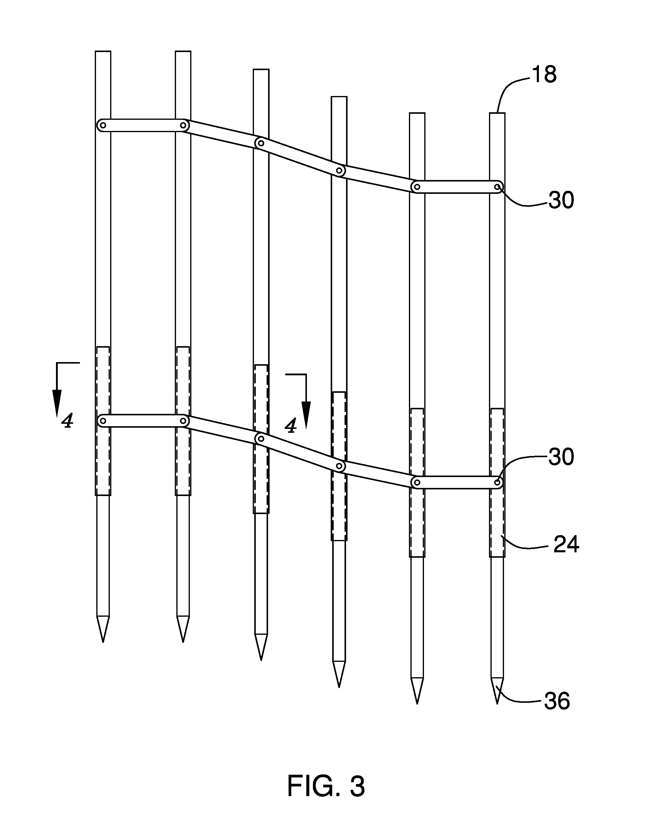
[0013] FIG. 3 is a front view of an embodiment of the disclosure.
[0014] FIG. 4 is a cross-sectional view of an embodiment of the disclosure taken along the line of 4-4 of FIG. 3.
[0015] FIG. 5 is a front view of an embodiment of the disclosure.
DETAILED DESCRIPTION OF THE INVENTION
[0016] With reference now to the drawings, and in particular to FIGS. 1 through 5 thereof, a new modular fence post device embodying the principles and concepts of an embodiment of the disclosure and generally designated by the reference numeral 10 will be described.
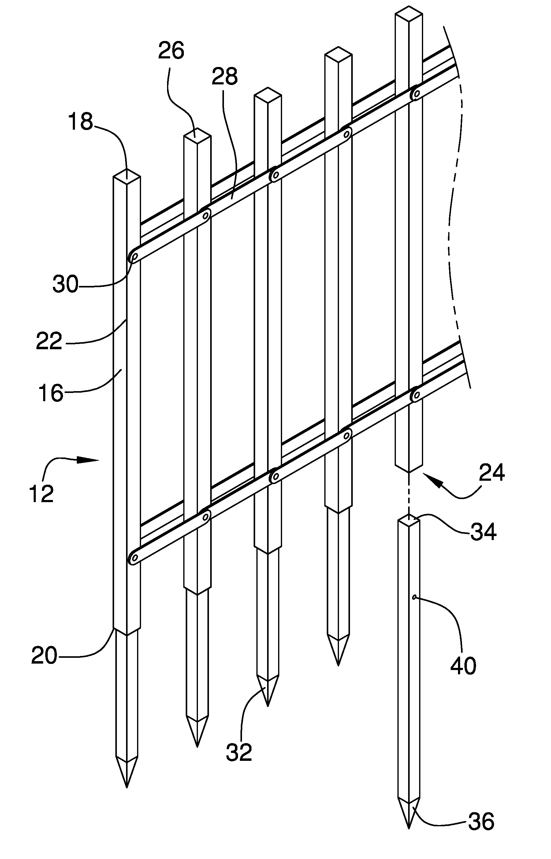
[0017] As best illustrated in FIGS. 1 through 5, the modular fence post assembly 10 generally comprises a fence assembly 12 configured to form a barrier on a sloped surface 14. The fence assembly 12 is comprised of a plurality of fence posts 16. Each of the fence posts has a top end 18, a bottom end 20 and a perimeter wall 22 that is attached to and extends between the top 18 and bottom ends 20. The bottom end 20 is open and defines a receiving space 24. Each of the top ends 18 comprises a planar surface 26 configured to be struck by a hammer. Each of the fence posts 16 has a height between 30.0 inches and 50.0 inches. The fence posts 16 are positioned adjacent to each other and lie in the same plane with respect to each other. The fence posts 16 each have a vertically orientated longitudinal axis.
[0018] A plurality of couplers 28 is attached to the fence posts 16. Each of the fence posts 16 is coupled to an adjacent one of the fence posts 16 by at least one of the couplers 28 such that a continuous wall is defined including each of the fence posts 16. The couplers 28 allow adjacent ones of the fence posts 16 to be vertically adjusted relative to each other while retaining the longitudinal axes in a vertical orientation. Each of the couplers 28 is comprised of an accordion hinge. Each of the fence posts 16 is coupled to the next adjacent one of the fence posts 16 with two of the couplers 28. Each of the couplers 28 is positioned between 4.0 inches and 12.0 inches from the top ends of the fence posts 16. The couplers 28 may be attached to the fence posts 16 by pins 30. The pins 30 may extend through the coupler 28 and the fence posts 16 such that the fence post 16 is vertically adjustable.
[0019] A plurality of ground anchors 32 each having a first end 34 and a second end 36. Each of the first ends 34 is removably extendable into the receiving space 24. Each of the second ends 36 is extendable into a ground surface 38. Each of the second ends 36 is configured for piercing and anchoring the fence post 16 in a ground surface 38. Each of the second ends 36 is pointed. Each of the ground anchors 32 extends outwardly from the bottom ends 20 a distance equal to at least 8.0 inches. The first ends 34 may have an aperture 40 extending therethrough. The apertures 40 are configured for securing the ground anchor 32 to the fence posts 16 such that a pin 30 may extend through the fence post 16 and through the aperture 40 securing the ground anchor 32 to the fence post 16.
[0020] In use, each of the first ends 34 of the ground anchors 32 is positioned into the receiving space 24 of each of the fence posts 16. The second end 36 of the ground anchors 32 are positioned over a ground surface 38 and the top end 18 of the fence post 16 should be hammered such that the ground anchor 32 pierces the ground surface 38 anchoring the fence post 16 to the ground surface 38. Each of the adjacent fence posts 16 may also be anchored into the ground surface 38. The couplers 28 allow the fence posts 16 to be vertically adjusted relative to each other such that a continuous wall of fence posts 16 may be anchored to a ground surface that is sloped.
[0021] With respect to the above description then, it is to be realized that the optimum dimensional relationships for the parts of an embodiment enabled by the disclosure, to include variations in size, materials, shape, form, function and manner of operation, assembly and use, are deemed readily apparent and obvious to one skilled in the art, and all equivalent relationships to those illustrated in the drawings and described in the specification are intended to be encompassed by an embodiment of the disclosure.
[0022] Therefore, the foregoing is considered as illustrative only of the principles of the disclosure. Further, since numerous modifications and changes will readily occur to those skilled in the art, it is not desired to limit the disclosure to the exact construction and operation shown and described, and accordingly, all suitable modifications and equivalents may be resorted to, falling within the scope of the disclosure. In this patent document, the word "comprising" is used in its non-limiting sense to mean that items following the word are included, but items not specifically mentioned are not excluded. A reference to an element by the indefinite article "a" does not exclude the possibility that more than one of the element is present, unless the context clearly requires that there be only one of the elements.
* * * * *
D00000
D00001
D00002
D00003
D00004
D00005
XML
uspto.report is an independent third-party trademark research tool that is not affiliated, endorsed, or sponsored by the United States Patent and Trademark Office (USPTO) or any other governmental organization. The information provided by uspto.report is based on publicly available data at the time of writing and is intended for informational purposes only.
While we strive to provide accurate and up-to-date information, we do not guarantee the accuracy, completeness, reliability, or suitability of the information displayed on this site. The use of this site is at your own risk. Any reliance you place on such information is therefore strictly at your own risk.
All official trademark data, including owner information, should be verified by visiting the official USPTO website at www.uspto.gov. This site is not intended to replace professional legal advice and should not be used as a substitute for consulting with a legal professional who is knowledgeable about trademark law.