Panelized Manufactured Stone Wall Covering With In Mold Formed Alignment Mechanism
Attebery, II; Harold C.
U.S. patent application number 16/197450 was filed with the patent office on 2019-03-21 for panelized manufactured stone wall covering with in mold formed alignment mechanism. The applicant listed for this patent is Harold C. Attebery, II. Invention is credited to Harold C. Attebery, II.
| Application Number | 20190085567 16/197450 |
| Document ID | / |
| Family ID | 59625390 |
| Filed Date | 2019-03-21 |


| United States Patent Application | 20190085567 |
| Kind Code | A1 |
| Attebery, II; Harold C. | March 21, 2019 |
PANELIZED MANUFACTURED STONE WALL COVERING WITH IN MOLD FORMED ALIGNMENT MECHANISM
Abstract
A manufactured stone panel formed of a cementitious manufactured stone panel having a rear, mounting face, a front, decorative face, an upper surface having a raised section and a recess, and a lower surface a raised section and a recess, such that the upper surface and lower surface of adjacent stone panels overlap to form a joint therebetween, at least one bracket extending from the cementitious stone body; a leftward extension on the stone body; and a rightward extension on the stone body, such that the leftward extension and rightward extension of adjacent stone panels form a joint therebetween.
| Inventors: | Attebery, II; Harold C.; (Tarpon Springs, FL) | ||||||||||
| Applicant: |
|
||||||||||
|---|---|---|---|---|---|---|---|---|---|---|---|
| Family ID: | 59625390 | ||||||||||
| Appl. No.: | 16/197450 | ||||||||||
| Filed: | November 21, 2018 |
Related U.S. Patent Documents
| Application Number | Filing Date | Patent Number | ||
|---|---|---|---|---|
| 15973495 | May 7, 2018 | |||
| 16197450 | ||||
| 15714544 | Sep 25, 2017 | |||
| 15973495 | ||||
| 15434345 | Feb 16, 2017 | |||
| 15714544 | ||||
| 62296589 | Feb 17, 2016 | |||
| Current U.S. Class: | 1/1 |
| Current CPC Class: | E04C 2/38 20130101; E04F 13/147 20130101; E04C 2002/008 20130101; E04C 2/041 20130101; E04F 2203/02 20130101; E04F 13/0835 20130101; E04F 13/141 20130101 |
| International Class: | E04F 13/14 20060101 E04F013/14; E04C 2/38 20060101 E04C002/38 |
Claims
1. A manufactured stone panel, comprising: a cementitious manufactured stone panel having: a rear, mounting face, a front, decorative face, an upper surface having a raised section and a recess, and a lower surface a raised section and a recess, such that the upper surface and lower surface of adjacent stone panels overlap to form a joint therebetween; at least one bracket extending from the cementitious stone body; a leftward extension on the stone body; and a rightward extension on the stone body, such that the leftward extension and rightward extension of adjacent stone panels form a joint therebetween.
2. A manufactured stone accessory panel, comprising: a cementitious manufactured stone panel having: a rear, mounting face, a front, decorative face, an upper surface having a raised section and a recess, and a lower surface a raised section and a recess, such that the upper surface and lower surface of adjacent stone panels overlap to form a joint therebetween.
3. A manufactured stone corner panel, comprising: a cementitious manufactured stone panel having: two rear, mounting faces, two front, decorative faces, the front faces forming a substantially right angle; an upper surface having a raised section and a recess, and a lower surface a raised section and a recess, such that the upper surface and lower surface of adjacent stone panels overlap to form a joint therebetween; a leftward extension on the stone body; and a rightward extension on the stone body, such that the leftward extension and rightward extension of adjacent stone panels form a joint therebetween.
Description
CROSS-REFERENCE TO RELATED APPLICATIONS
[0001] This application is a continuation of U.S. patent application Ser. No. 15/973,495, filed May 7, 2018, entitled "PANELIZED MANUFACTURED STONE WALL COVERING WITH IN MOLD FORMED ALIGNMENT MECHANISM," which is a continuation of U.S. patent application Ser. No. 15/714,544, filed Sep. 25, 2017, entitled "PANELIZED MANUFACTURED STONE WALL COVERING WITH IN MOLD FORMED ALIGNMENT MECHANISM," which is a continuation of U.S. patent application Ser. No. 15/434,345, filed Feb. 16, 2017, entitled "PANELIZED MANUFACTURED STONE WALL COVERING WITH IN MOLD FORMED ALIGNMENT MECHANISM," which claims the benefit of U.S. Provisional Application Ser. No. 62/296,589, filed Feb. 17, 2016, entitled "PANELIZED MANUFACTURED STONE WALL COVERING WITH IN MOLD FORMED ALIGNMENT MECHANISM," which are hereby incorporated herein by reference in their entirety--including all references and appendices cited therein.
STATEMENT REGARDING FEDERALLY SPONSORED RESEARCH OR DEVELOPMENT
[0002] Not applicable.
REFERENCE TO A SEQUENCE LISTING
[0003] Not applicable.
BACKGROUND OF THE INVENTION
[0004] A variety of manufactured stone has come onto the market. Generally, the manufactured stone is mounted to a prepared surface with mortar, screws or a polymer adhesive. Substantial preparation of the wall is required because the manufactured stone. Generally, the stones are preformed individual stones that are adhered to the wall. Recently, panelized products that appear to have a number of individual stones have become popular due to the speed and ease of installation.
SUMMARY OF THE INVENTION
[0005] The present invention is directed to, in one embodiment, panelized manufactured stone for use on the exterior of a building and/or structure.
BRIEF DESCRIPTION OF THE DRAWINGS
[0006] Certain embodiments of the present invention are illustrated by the accompanying figures. It will be understood that the figures are not necessarily to scale and that details not necessary for an understanding of the invention or that render other details difficult to perceive may be omitted. It will be further understood that the invention is not necessarily limited to the particular embodiments illustrated herein.
[0007] The invention will now be described with reference to the drawings wherein:
[0008] FIG. 1 illustrates a front perspective view of a manufactured stone panel in accordance with the present invention;
[0009] FIG. 2 illustrates a front plan view of a manufactured stone panel in accordance with the present invention;
[0010] FIG. 3 illustrates a top plan view of a manufactured stone panel in accordance with the present invention;
[0011] FIG. 4A illustrates a plan assembly view of the side of a manufactured stone panel installed on a wall in accordance with the present invention;
[0012] FIG. 4B illustrates a plan assembly view in detail of an alternate embodiment of a manufactured stone panel installed on a wall in accordance with the present invention;
[0013] FIG. 5 illustrates a front view of a manufactured stone panel in accordance with the present invention;
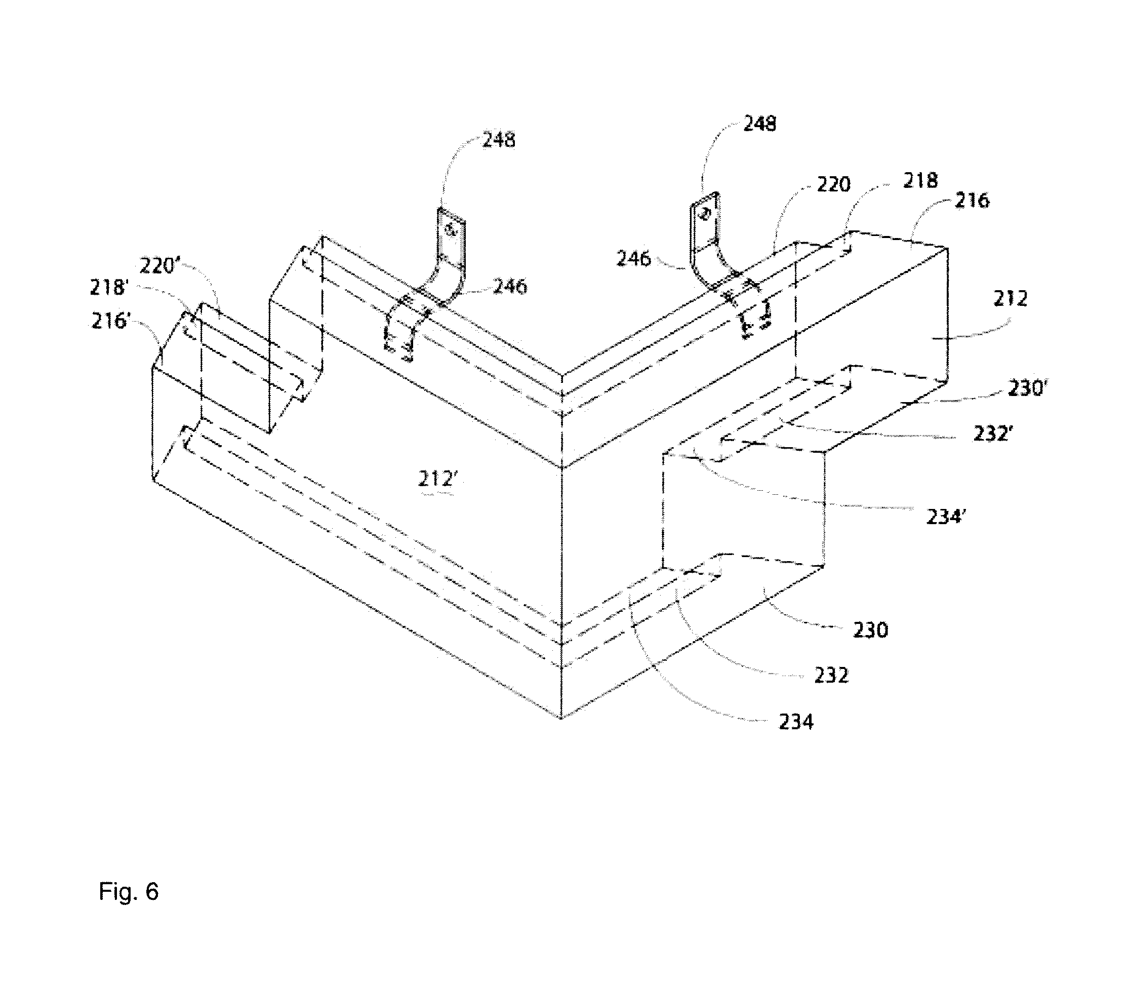
[0014] FIG. 6 illustrates a perspective view of a corner piece of a manufactured stone panel of the present invention in accordance with the present invention;
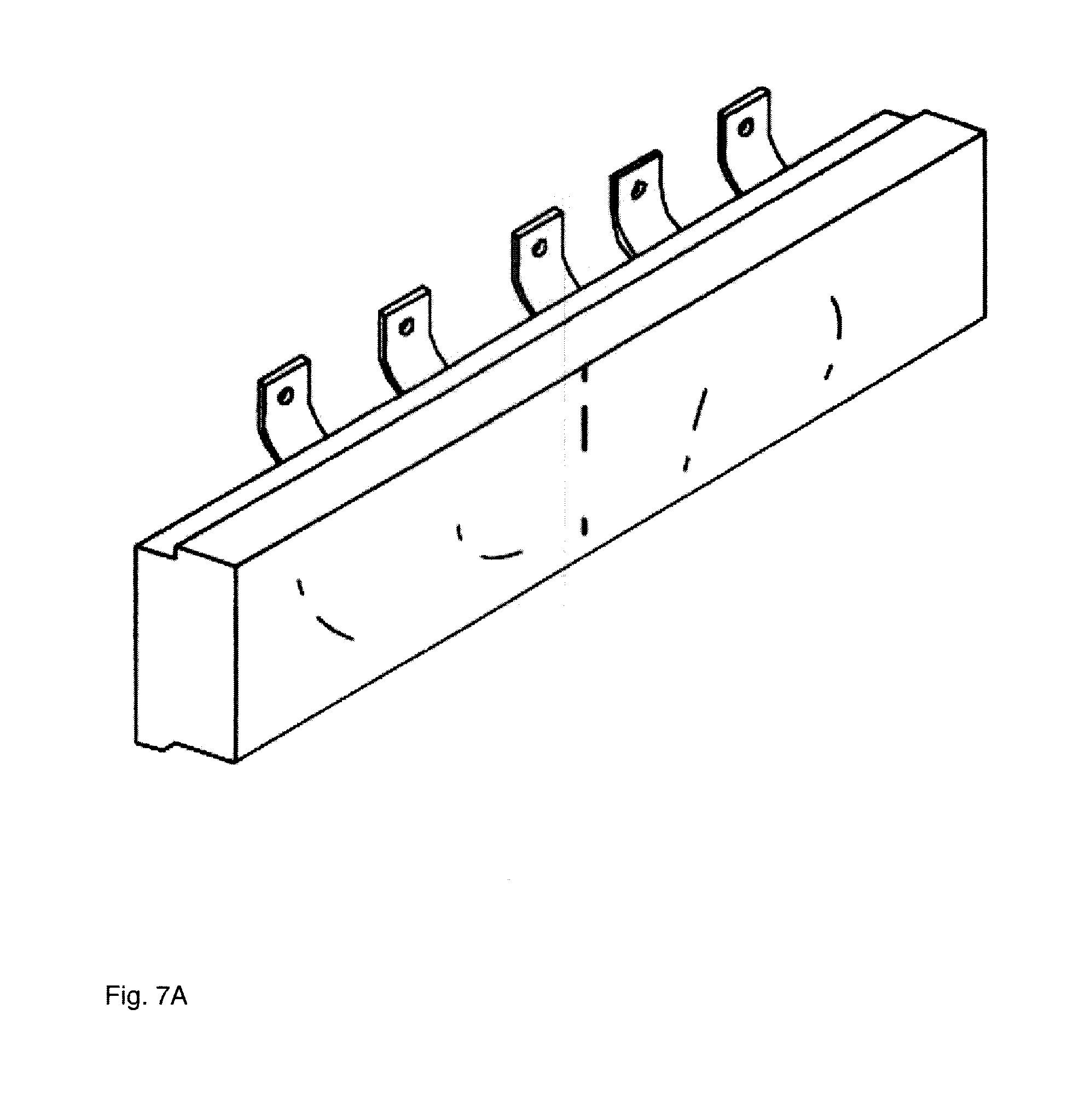
[0015] FIG. 7A illustrates a front perspective view of an alternate embodiment of a manufactured stone panel in accordance with the present invention; and
[0016] FIG. 7B illustrates a rear plan view, in detail, of an alternate embodiment of a manufactured stone panel in accordance with the present invention.
DETAILED DESCRIPTION OF THE INVENTION
[0017] The present invention will now be described with occasional reference to the specific embodiments of the invention. This invention may, however, be embodied in different forms and should not be construed as limited to the embodiments set forth herein. Rather, these embodiments are provided so that this disclosure will be thorough and complete, and will fully convey the scope of the invention to those skilled in the art.
[0018] Unless otherwise defined, all technical and scientific terms used herein have the same meaning as commonly understood by one of ordinary skill in the art to which this invention belongs. The terminology used in the description of the invention herein is for describing particular embodiments only and is not intended to be limiting of the invention. As used in the description of the invention and the appended claims, the singular forms "a," "an," and "the" are intended to include the plural forms as well, unless the context clearly indicates otherwise.
[0019] Unless otherwise indicated, all numbers expressing quantities of ingredients, properties such as molecular weight, reaction conditions, and so forth as used in the specification and claims are to be understood as being modified in all instances by the term "about." Accordingly, unless otherwise indicated, the numerical properties set forth in the specification and claims are approximations that may vary depending on the desired properties sought to be obtained in embodiments of the present invention. Notwithstanding that the numerical ranges and parameters setting forth the broad scope of the invention are approximations, the numerical values set forth in the specific examples are reported as precisely as possible. Any numerical values, however, inherently contain certain errors necessarily resulting from error found in their respective measurements.
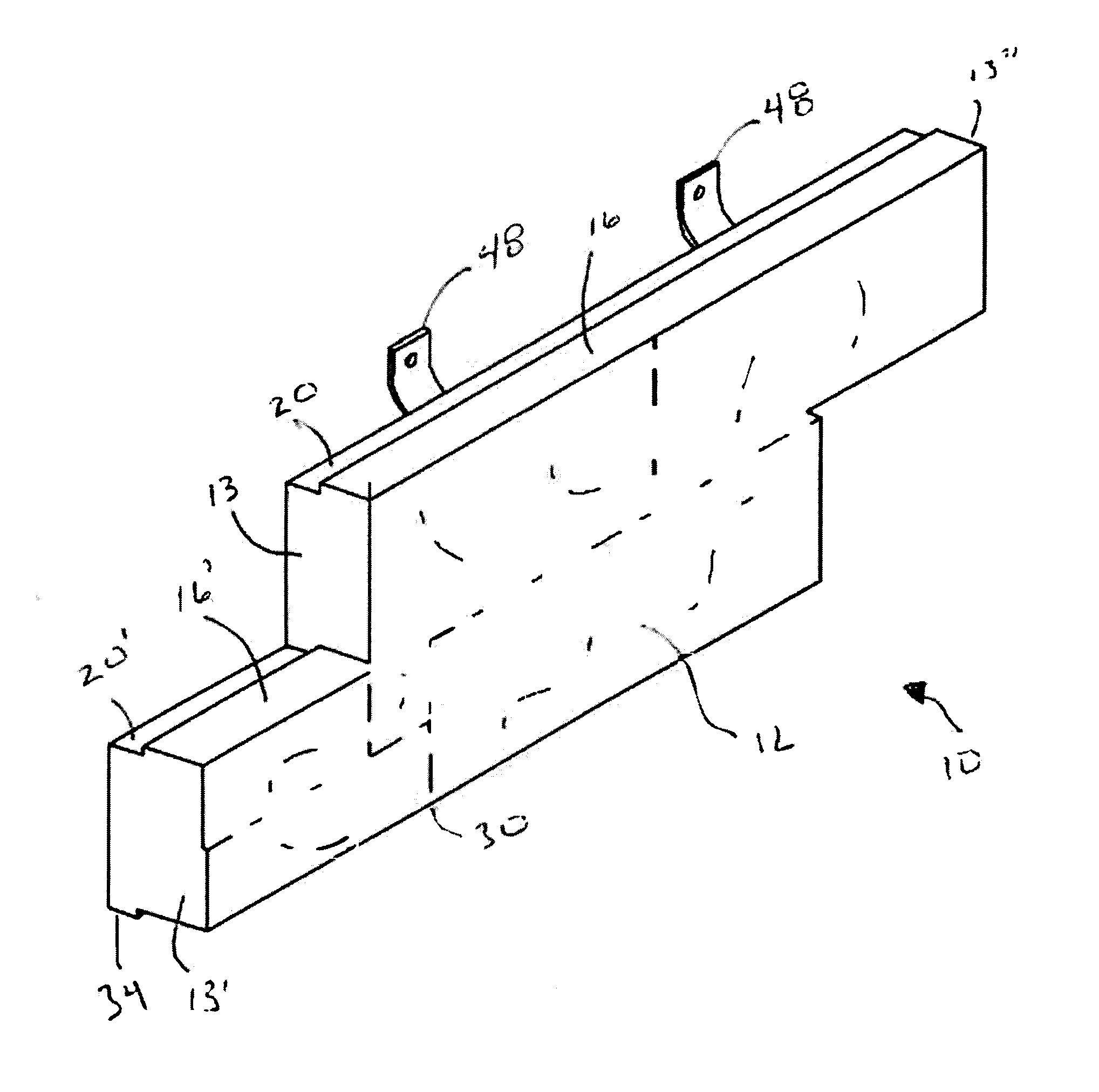
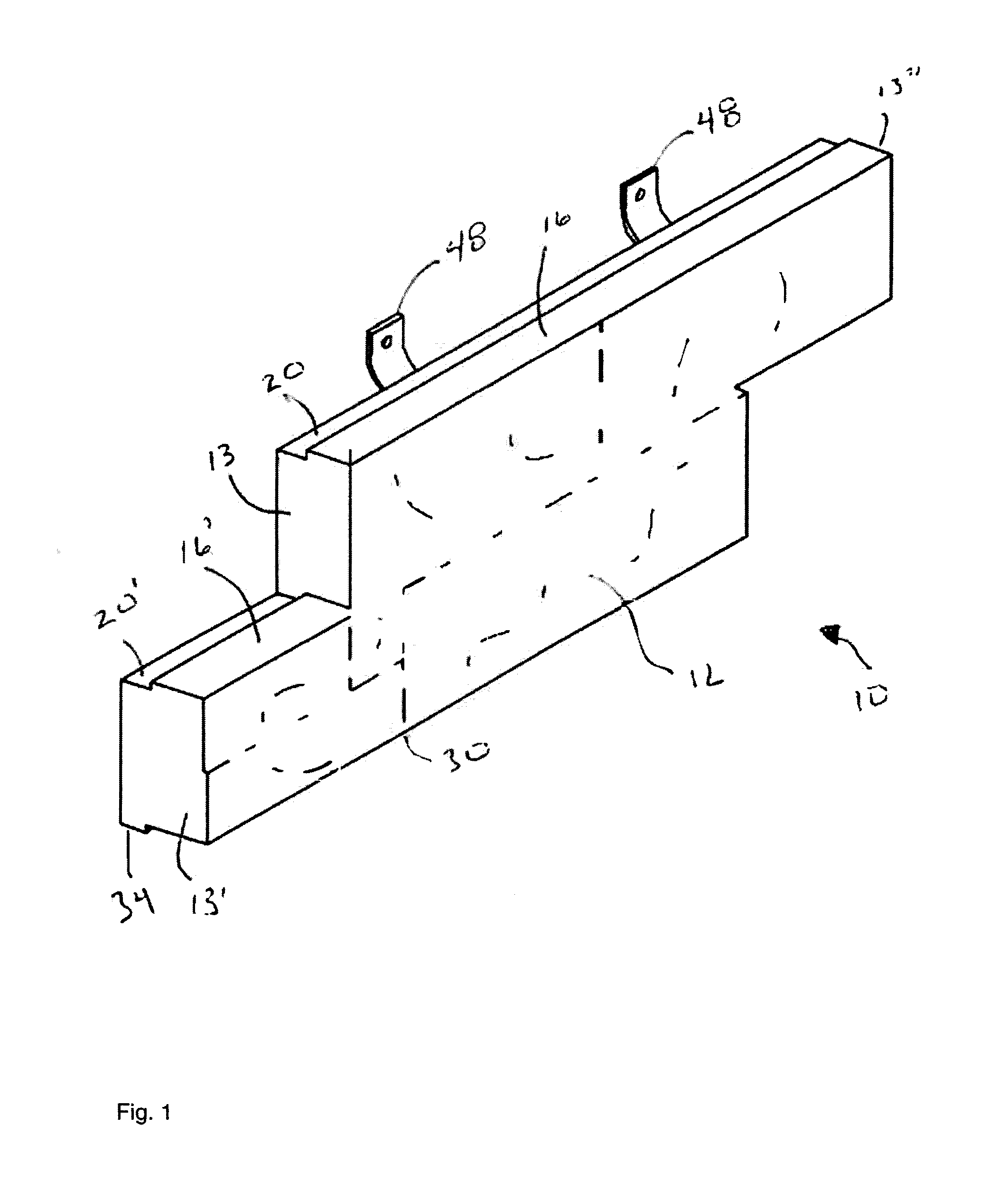
[0020] FIG. 1 illustrates a front perspective view of a manufactured stone panel in accordance with the present invention. The manufactured stone panel 10 includes a formed concrete body 12 that is mounted to the wall of a structure by brackets 48. The manufactured stone panels form a decorative counter flashing to the exterior of a structure. The panels may be installed as a wainscot or may be installed on the entire surface of the structure. In order to break up the vertical lines of the installed panels, the manufactured stone panel includes right and left extensions. When installed, the panels join together such that the right and left extensions of adjacent panels coordinate and the vertical seams on the wall are difficult to perceive. The upper surface of the manufactured stone panel includes a raised section and a recess. The lower surface of the manufactured stone panel includes a raised section and a recess. When installed the recess of the upper section receives of one manufactured stone panel mates with the raised section in an adjacent manufactured stone panel. The overlap inhibits the flow of water from the front surface of the manufactured stone panel to the rear face where it must drain or evaporate.
[0021] Manufactured stone panels in accordance with the present invention are typically cast from concrete. The concrete is placed in an elastomeric mold and placed on a vibrating table to improve the surface properties of the panel. Brackets are added and the mold is stored for a period to allow the concrete to set. The mold is generally formed by spraying an elastomeric material over a set of natural stones have the desired appearance. Preferably, the stones are arranged within a frame that holds the stones in place during the mold forming process and provides a high quality and repeatable side surface detail, so that the manufactured stone panel align well when mounted on a wall.
[0022] FIG. 2 illustrates a front plan view of a manufactured stone panel in accordance with the present invention. The front surface may be of any character, while natural stone is generally desired in the market other surface features may be molded. The sidewalls 13, 13' may be perpendicular to the front face. However, angling the sidewalls at an angle of up to about 45 degrees improves the appearance of the manufactured stone panels when mounted and improves the resistance to windblown water. The sidewalls my also include a stepped edge, similar to the upper and lower surface of the panel, so that the sidewalls of adjacent panels mate.
[0023] FIG. 3 illustrates a top plan view of a manufactured stone panel in accordance with the present invention. The front surface includes a decorative face while the rear surface is generally as poured or may be roughly troweled. The sidewalls 13, 13' shown are at an angle of 10-30 degrees to improve the appearance and weather resistance.
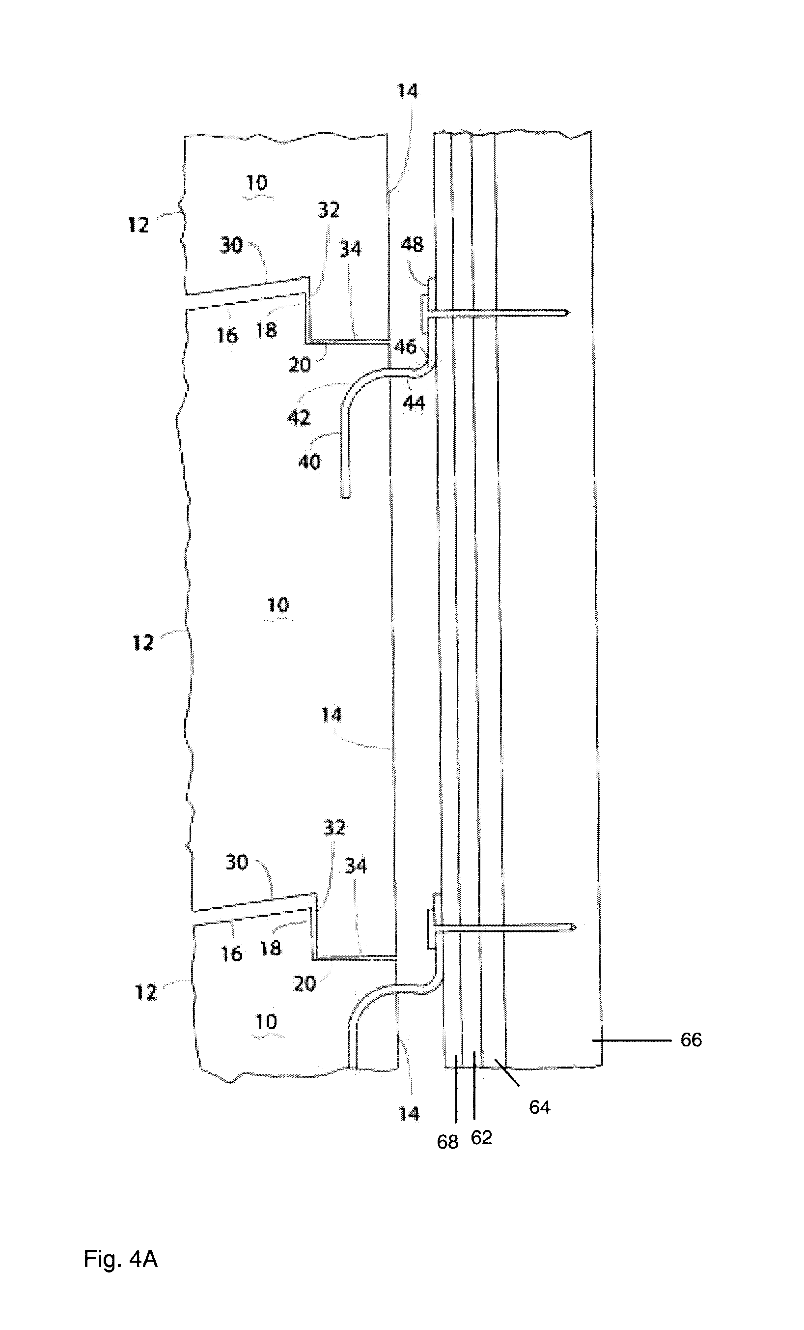
[0024] FIG. 4A illustrates a plan assembly view of the side of a manufactured stone panel installed on a wall in accordance with the present invention. Manufactured stone panels are mounted on an exterior wall of a structure.
[0025] The wall may be any construction. Generally, a plywood or OSB panel is covered with a one or more barrier layers such as tarpaper. An exterior drainage plane layer is typically used to allow water to flow down the face of the wall. The manufactured stone panels are preferably nailed to the wall panel. The lower tier of manufactured stone panels is mounted and a second tier is placed on top such that the recess in the lower panel receives the raised section of the upper panel. The upper panel is then tiled up and fixed to the wall. A third tier of manufactured stone panels is then installed in the same manner. As can be seen the lower surface includes an optional descending section.
[0026] FIG. 4B illustrates a plan assembly view in detail of an alternate embodiment of a manufactured stone panel installed on a wall in accordance with the present invention. The first tier of manufactured stone panels is shown. A starter strip/drip ledge is installed along the base of the wall. The lower edge of the manufactured stone panel is placed on the strip so that the raised portion of the lower surface fits onto a channel on the strip. The panel is then tilted up and fixed to the wall.
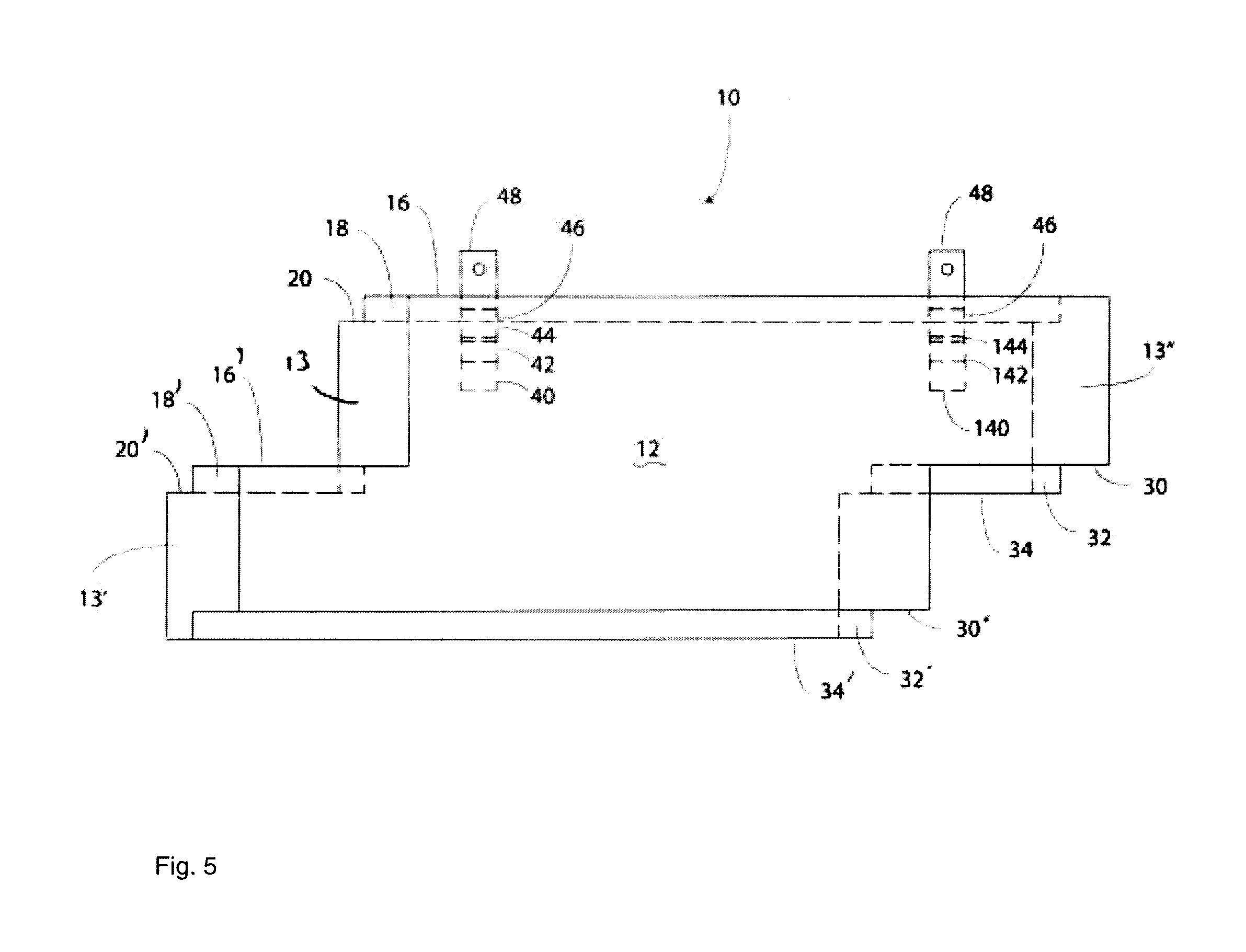
[0027] FIG. 5 illustrates a front view of a manufactured stone panel in accordance with the present invention. As can be seen in FIG. 5, the brackets extend into the concrete of the panel. While an upper and lower bracket may be used, this is generally not necessary.
[0028] FIG. 6 illustrates a perspective view of a corner piece of a manufactured stone panel of the present invention in accordance with the present invention. The corner piece is structurally similar to the standard manufactured stone panel. Brackets extend from the rear of each side of the corner piece. The upper and lower surfaces include raised sections and recesses and the end sections may be perpendicular or angled from surface or may include a step feature. The corner piece is installed in a manner similar to the planar manufactured stone panel.
[0029] FIG. 7A illustrates a front perspective view of an alternate embodiment of a manufactured stone panel in accordance with the present invention. An accessory manufactured stone panel may be included with the standard manufactured stone panel. A number of brackets are included so that the accessory piece may be cut to any length and have at least one mounting bracket. The accessory piece may also be installed on the wall to break up the horizontal lines on the standard panel. Generally 5% -10% accessory pieces mixed in with the standard panels on the wall will provide an improve appearance by breaking up the horizontal runs of the installed panels.
[0030] FIG. 7B illustrates a rear plan view, in detail, of an alternate embodiment of a manufactured stone panel in accordance with the present invention.
[0031] The present invention should not be considered limited to the specific examples described herein, but rather should be understood to cover all aspects of the invention. Various modifications, equivalent processes, as well as numerous structures and devices to which the present invention may be applicable will be readily apparent to those of skill in the art. Those skilled in the art will understand that various changes may be made without departing from the scope of the invention, which is not to be considered limited to what is described in the specification.
* * * * *
D00000
D00001
D00002
D00003
D00004
D00005
D00006
D00007
D00008
XML
uspto.report is an independent third-party trademark research tool that is not affiliated, endorsed, or sponsored by the United States Patent and Trademark Office (USPTO) or any other governmental organization. The information provided by uspto.report is based on publicly available data at the time of writing and is intended for informational purposes only.
While we strive to provide accurate and up-to-date information, we do not guarantee the accuracy, completeness, reliability, or suitability of the information displayed on this site. The use of this site is at your own risk. Any reliance you place on such information is therefore strictly at your own risk.
All official trademark data, including owner information, should be verified by visiting the official USPTO website at www.uspto.gov. This site is not intended to replace professional legal advice and should not be used as a substitute for consulting with a legal professional who is knowledgeable about trademark law.