Cyclic Process Using Alkaline Solutions Created From Electrolytically Decarboxylated Water As An Atmosphereic Co2 Collector Followed By Repeated Electrochemical Recovery Of Co2 With Simultaneous Production Of Dihydrogen For Liquid Hydrocarbon Synthesis
Willauer; Heather D. ; et al.
U.S. patent application number 16/045863 was filed with the patent office on 2019-03-21 for cyclic process using alkaline solutions created from electrolytically decarboxylated water as an atmosphereic co2 collector followed by repeated electrochemical recovery of co2 with simultaneous production of dihydrogen for liquid hydrocarbon synthesis. The applicant listed for this patent is The Goverment of the United States of America, as represented by the Secretary of the Navy, The Goverment of the United States of America, as represented by the Secretary of the Navy. Invention is credited to Felice DiMascio, Dennis R. Hardy, Heather D. Willauer, Frederick Williams.
| Application Number | 20190085472 16/045863 |
| Document ID | / |
| Family ID | 65039852 |
| Filed Date | 2019-03-21 |


| United States Patent Application | 20190085472 |
| Kind Code | A1 |
| Willauer; Heather D. ; et al. | March 21, 2019 |
CYCLIC PROCESS USING ALKALINE SOLUTIONS CREATED FROM ELECTROLYTICALLY DECARBOXYLATED WATER AS AN ATMOSPHEREIC CO2 COLLECTOR FOLLOWED BY REPEATED ELECTROCHEMICAL RECOVERY OF CO2 WITH SIMULTANEOUS PRODUCTION OF DIHYDROGEN FOR LIQUID HYDROCARBON SYNTHESIS
Abstract
A method for the controlled removal of bicarbonate from alkaline water and its replacement with a strong base that is capable of chemically absorbing CO.sub.2 from the atmosphere as a carbonate and bicarbonate solution. This bicarbonate and carbonate solution is reprocessed in the central compartment of an electrolytic cation exchange module (E-CEM) to take advantage of the removal of CO.sub.2 from the air, and as an energetic byproduct of E-CEM dihydrogen production, and to regenerate the original strong base absorbent solution. Thus, this process is cyclical in nature, and no chemicals are needed except an initial source of alkaline water.
| Inventors: | Willauer; Heather D.; (Fairfax Station, VA) ; Hardy; Dennis R.; (Fredericksburg, VA) ; DiMascio; Felice; (Simsbury, CT) ; Williams; Frederick; (Accokeek, MD) | ||||||||||
| Applicant: |
|
||||||||||
|---|---|---|---|---|---|---|---|---|---|---|---|
| Family ID: | 65039852 | ||||||||||
| Appl. No.: | 16/045863 | ||||||||||
| Filed: | July 26, 2018 |
Related U.S. Patent Documents
| Application Number | Filing Date | Patent Number | ||
|---|---|---|---|---|
| 62537139 | Jul 26, 2017 | |||
| Current U.S. Class: | 1/1 |
| Current CPC Class: | B01D 2252/1035 20130101; B01D 53/14 20130101; C25B 1/10 20130101; C25B 1/14 20130101; C25B 1/16 20130101; B01D 2251/606 20130101; C25B 15/08 20130101; B01D 53/1493 20130101; B01D 53/1425 20130101; C10G 2/50 20130101; C25B 9/08 20130101; B01D 2258/06 20130101; B01D 53/1475 20130101; B01D 2251/304 20130101 |
| International Class: | C25B 1/14 20060101 C25B001/14; C25B 15/08 20060101 C25B015/08 |
Claims
1. A cyclical method for producing a strong alkaline solution for atmospheric CO.sub.2 capture, subsequently followed by recovery of the CO.sub.2 along with regeneration of the alkaline solution to complete the cycle, comprising: feeding an alkaline solution containing bicarbonate and carbonate ions into an electrochemical module to form a hydroxide solution; allowing the hydroxide solution to chemically absorb CO.sub.2 from the atmosphere to form a re-equilibrated bicarbonate and carbonate solution; and feeding the re-equilibrated bicarbonate and carbonate solution back into the electrochemical module.
2. The method of claim 1, wherein the pH of the hydroxide solution decreases as the CO.sub.2 from the atmosphere is absorbed.
3. The method of claim 1, wherein the hydroxide solution is regenerated in the electrochemical module from the re-equilibrated bicarbonate and carbonate solution fed into the electrochemical module.
4. The method of claim 1, additionally comprising adjusting a surface to volume ratio of the hydroxide solution to maximize the absorption rate of CO.sub.2 from the atmosphere into the hydroxide solution.
5. The method of claim 1, wherein as the pH and hydroxide concentration increase in the hydroxide solution, the rate of CO.sub.2 absorption from the atmosphere into the hydroxide solution increases.
6. The method of claim 1, wherein the hydroxide solution comprises an alkali metal hydroxide.
7. The method of claim 1, wherein the hydroxide solution comprises sodium hydroxide.
8. A cyclical method for producing a strong alkaline solution for atmospheric CO.sub.2 capture, subsequently followed by recovery of the CO.sub.2 along with simultaneous production of dihydrogen and regeneration of the alkaline solution to complete the cycle, comprising: feeding an alkaline solution containing bicarbonate and carbonate ions into a center compartment of an electrolytic cation exchange module (E-CEM), wherein the E-CEM comprises an anode, an anode compartment adjacent to the anode, a first cation membrane between the anode compartment and the center compartment, the center compartment, a cathode compartment, a second cation membrane between the center compartment and the cathode compartment, and a cathode adjacent to the cathode compartment; feeding water into the anode compartment and cathode compartment; applying a source of electricity to the anode, wherein O.sub.2 is formed in the anode compartment, CO.sub.2 is formed in the center compartment, and H.sub.2 and hydroxide are formed in the cathode compartment; removing the CO.sub.2 formed in the center compartment and the H.sub.2 formed in the cathode compartment; collecting an effluent from the cathode compartment comprising the hydroxide formed in the cathode compartment; allowing the effluent from the cathode compartment to chemically absorb CO.sub.2 from the atmosphere to form a re-equilibrated bicarbonate and carbonate solution; and feeding the re-equilibrated solution back into the center compartment of the E-CEM.
9. The method of claim 8, wherein the pH of the effluent from the cathode compartment decreases as the CO.sub.2 from the atmosphere is absorbed.
10. The method of claim 8, wherein an effluent from the anode compartment, an effluent from the center compartment, or both are combined with the effluent from the cathode compartment to form a combined effluent, and wherein the combined effluent chemically absorbs CO.sub.2 from the atmosphere to form a re-equilibrated bicarbonate and carbonate solution.
11. The method of claim 10, wherein the pH of the combined effluent decreases as the CO.sub.2 from the atmosphere is absorbed.
12. The method of claim 8, wherein hydroxide is regenerated in the cathode compartment from the re-equilibrated bicarbonate and carbonate solution fed into the center compartment.
13. The method of claim 8, additionally comprising adjusting a surface to volume ratio of the cathode effluent to maximize the absorption rate of CO.sub.2 from the atmosphere into the effluent from the cathode compartment.
14. The method of claim 8, additionally comprising increasing the applied electricity to increase the pH and hydroxide concentration of the effluent from the cathode compartment.
15. The method of claim 8, wherein as the pH and hydroxide concentration increase in the effluent from the cathode compartment, the rate of CO.sub.2 absorption from the atmosphere into the effluent from the cathode compartment increases.
16. The method of claim 8, wherein the hydroxide formed in the cathode compartment comprises an alkali metal hydroxide.
17. The method of claim 8, wherein the hydroxide formed in the cathode compartment comprises sodium hydroxide.
Description
PRIORITY CLAIM
[0001] The present application is a non-provisional application claiming the benefit of U.S. Provisional Application No. 62/537,139 filed on Jul. 26, 2017 by Heather D Willauer et al., entitled "A CYCLIC PROCESS USING ALKALINE SOLUTIONS CREATED FROM ELECTROLYTICALLY DECARBOXYLATED WATER AS AN ATMOSPHERIC CO2 COLLECTOR FOLLOWED BY REPEATED ELECTROCHEMICAL RECOVERY OF CO2 WITH SIMULTANEOUS PRODUCTION OF DIHYDROGEN FOR LIQUID HYDORCARBON SYNTHESIS AS STORED ENERGY," the entire contents of which is incorporated herein by reference.
BACKGROUND OF THE INVENTION
Field of the Invention
[0002] The present invention relates to processing seawater or alkaline solutions for repeated recovery of CO.sub.2 to be used as feedstock to synthesize fuel.
Description of the Prior Art
[0003] Carbon dioxide (CO.sub.2) is reported to be a cause of climate change and responsible for ocean acidification as the world's oceans uptake CO.sub.2 by hydrolysis. Ocean acidification and decline in the oceans' carbonate-ion concentration is deteriorating coral reefs and impacting shell-forming marine organisms. (Orr et al., "Anthropogenic ocean acidification over the twenty-first century and its impact ion calcifying organisms, Nature, 437, 681-686 (2005) and Hoegh-Guldbergo Mumby et al., "Coral Reefs Under Rapid Climate Change and Ocean Acidification," Science, 318, 1737-1742 (2007)). The world's oceans contain approximately 100 mg/L of total CO.sub.2 of which 96% to 97% is bound as bicarbonate (HCO.sub.3.sup.-). This amounts to approximately one third of the concentration of a fossil fuel stack gas effluent on a weight per volume basis. This bicarbonate/carbonate is responsible for buffering and maintaining the ocean's pH which is relatively constant below the first 100 meters. (Takahasi et al., "The Alkalinity and Total Carbon Dioxide Concentration in the World Oceans," Carbon Cycle Modell., Vol. 16; SCOPE: NY, USA, pp 271-286 (1982) and Takahasi et al., "Carbonate Chemistry of the Surface of the Waters of the World Oceans," Isotope Marine Chemistry; Goldberg, Horibe, Katsuko, eds.; Uchida Rokakuho: Tokyo, Japan, pp 291-326 (1980)). This dissolved bicarbonate and carbonate is essentially bound CO.sub.2, and the sum of these species along with gaseous CO.sub.2, shown in equation 1, represents the total carbon dioxide concentration [CO.sub.2].sub.T, of seawater.
.SIGMA.[CO.sub.2].sub.T=[CO.sub.2(g)]+[HCO.sub.3.sup.-]+[CO.sub.3.sup.2-- ] (1)
[0004] An electrochemical process has been developed and patented by the Naval Research Laboratory (NRL) that uses pH to exploit seawater as a means to recover CO.sub.2 from the sea. (Willauer et al., "Development of an Electrochemical Acidification Cell for the Recovery of CO.sub.2 and H.sub.2 from Seawater II. Evaluation of the cell by Natural Seawater," I&EC, 51, 11254-11260 (2012); Willauer et al., "Feasibility of CO.sub.2 extraction from seawater and simultaneous hydrogen gas generation using a novel and robust electrolytic cation exchange module based on continuous electrodeionization technology," I&EC, 53, 12192-12200 (2014); U.S. Pat. No. 9,303,323 to DiMascio et al. (Apr. 5, 2016); Willauer et al., "Development of an Electrolytic Cation Exchange Module for the Simultaneous Extraction of Carbon Dioxide and Hydrogen Gas from Natural Seawater," Energy Fuels, 31, 1723-1730 (2017); and U.S. Pat. No. 9,719,178 to DiMascio et al. (Aug. 1, 2017)). Johnson, et al. demonstrated that when the pH of seawater is decreased to 6 or less, carbonate and bicarbonate in the seawater are re-equilibrated to CO.sub.2 gas (equation 2). (Johnson et al., "Coulometric TCO.sub.2 Analyses for Marine Studies: An Introduction," Marine Chem., 16, 61 (1985)).
HCO.sub.3.sup.-+H.sup.+.revreaction.H.sub.2CO.sub.3.revreaction.H.sub.2O- +CO.sub.2(g).uparw. (2)
[0005] This method has been the basis for standard quantitative ocean total [CO.sub.2].sub.T measurements for over 25 years. (Johnson et al., "Coulometric TCO.sub.2 Analyses for Marine Studies: An Introduction," Marine Chem., 16, 61 (1985)). In addition to recovery of CO.sub.2 from seawater, NRL's electrolytic cation exchange module (E-CEM) simultaneously produces hydrogen gas through electrolytic dissociation of water at the cathode. Carbon and hydrogen serve as the principle building blocks to synthesis liquid hydrocarbons to be used as fuel. Water is broken down at the anode to H.sup.+ and O.sub.2 (equation 3).
At the Anode: 2H.sub.2O.fwdarw.4H.sup.++O.sub.2+4e.sup.- (3)
[0006] The O.sub.2 gas is flushed from the anode compartment with the flow of the anolyte water. The H.sup.+ ions are driven from the surface of the anode, through the cation-permeable membrane, and into the center compartment where they replace the Na.sup.+ in the flowing seawater. This causes the effluent seawater to be acidified without the need for any additional chemicals. At a seawater pH less than or equal to 6, the bicarbonate and carbonate in the seawater are re-equilibrated to carbonic acid (equation 4).
Center Compartment: 2H.sup.++2Na.sup.++2HCO.sub.3.sup.-.fwdarw.2H.sub.2CO.sub.3+2Na.sup.+ (4)
[0007] The CO.sub.2 from the carbonic acid in the effluent acidified seawater is vacuum stripped by a gas permeable membrane contactor equation 5. (U.S. Pat. No. 8,663,365 to Willauer et al. (Mar. 4, 2014)).
Center Compartment Acidified Seawater Effluent: 2H.sub.2CO.sub.3.fwdarw.2H.sub.2O+2CO.sub.2 (5)
[0008] The Na.sup.+ ions from the seawater in the center compartment are passed through the cation permeable membrane closest to the cathode. Water is decomposed at the cathode to H.sub.2 gas and OH.sup.- equation 6.
At the Cathode: 4H.sub.2O+4e.sup.-.fwdarw.4OH.sup.-+2H.sub.2 (6)
[0009] The NaOH and H.sub.2 gas are continuously flushed from the cathode compartment with the flow of the catholyte water. The acidified seawater is recombined with the solutions from the cathode and anode compartment. The overall reaction in equation 7 shows that chemically each mole of HCO.sub.3.sup.- (a weak base) in seawater is replaced with a mole of OH.sup.- (strong hydroxide base). (Willauer et al., "Development of an Electrolytic Cation Exchange Module for the Simultaneous Extraction of Carbon Dioxide and Hydrogen Gas from Natural Seawater," Energy Fuels, 31, 1723-1730 (2017)).
Overall chemical reaction: 2H.sub.2O+2HCO.sub.3.sup.-.fwdarw..sub.2OH.sup.-+O.sub.2+2H.sub.2+2CO.sub- .2 (7)
[0010] The industrial state of the art is to use strong alkaline solutions for the chemical absorption of CO.sub.2 from air or stack gas into amine-based solvents such as mono-ethanol-amine (MEA). MEA is highly volatile, highly corrosive, and degrades over time. In addition, alkaline solutions are very energy intensive because they cannot be regenerated from carbonate and bicarbonate solution created by chemical absorption of CO.sub.2. (Yoo et al., J. Envi. Mang., 53, 512-219 (2013); Mahmoudkhani et al., Inter. J. Green Gas. Cont., 3, 376-384 (2009); and Baciocchi et al., Chem. Eng. Proc., 1047-1058 (2006)).
BRIEF SUMMARY OF THE INVENTION
[0011] The present invention provides controlled removal of bicarbonate and carbonate (in the form of a weak acid, H.sub.2CO.sub.3) from either natural or synthetic alkaline water solutions and its replacement with a strong base containing hydroxide (e.g. sodium hydroxide) that is capable of rapidly chemically absorbing CO.sub.2 from the atmosphere as, e.g., NaHCO.sub.3 solution. NaHCO.sub.3 solution can then be reprocessed by the electrolytic cation exchange module (E-CEM) to take advantage of the removal of CO.sub.2 from the air, as an energetic by-product of E-CEM dihydrogen production. This process is cyclical in nature, and no chemicals are needed except the initial alkaline water solution.
[0012] Carbon serves as one of the principle building blocks needed to synthesize hydrocarbon fuel. Once inorganic carbon (CO.sub.2) from alkaline water sources is removed, a much stronger alkaline solution is formed that is capable of re-equilibrating with CO.sub.2 from the atmosphere by chemical absorption to the alkaline water that can be subsequently electrolytically reprocessed for CO.sub.2 recovery. The controlled removal of bicarbonate from alkaline water and replacement with hydroxide that promotes the formation of carbonates upon chemical adsorption of CO.sub.2 is a potential solution to ocean acidification. The feedstocks will produce renewable hydrocarbons that are superior in performance to fossil derived hydrocarbons and are drop in replacements for all current engines.
[0013] Alkaline solutions can be defined in this disclosure to include artificial solutions of carbonate, bicarbonate, and hydroxide produced from, e.g., sodium hydroxide, sodium carbonate, and sodium bicarbonate to be processed by the E-CEM for CO.sub.2 harvesting.
[0014] These and other features and advantages of the invention, as well as the invention itself, will become better understood by reference to the following detailed description, appended claims, and accompanying drawings.
BRIEF DESCRIPTION OF THE DRAWINGS
[0015] FIG. 1 is a diagram of an electrolytic cation exchange module (E-CEM).
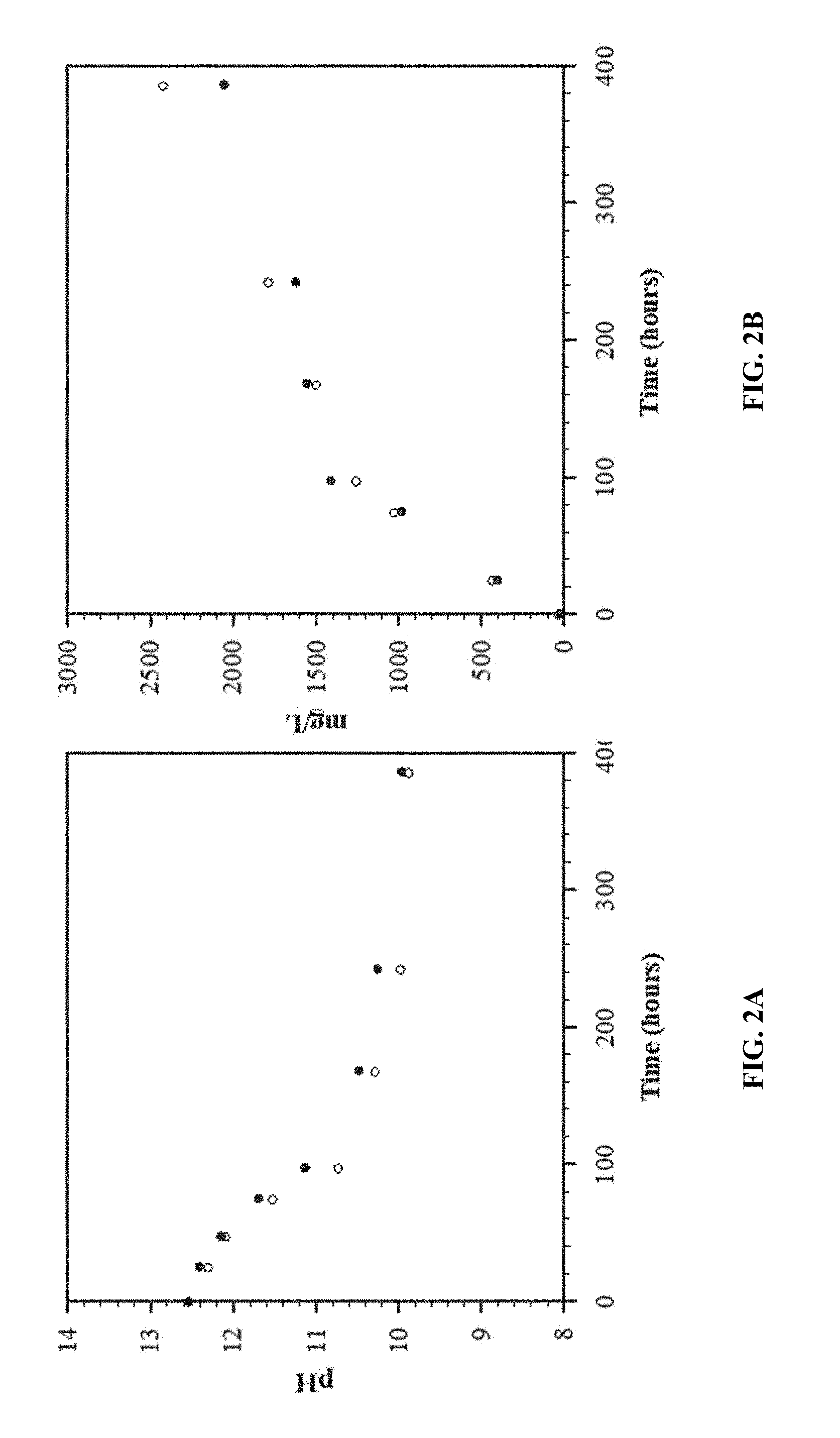
[0016] FIGS. 2A and 2B show CO.sub.2 absorption in 0.05 molar NaOH as a function of time (open circles stirred). FIG. 2A shows how the pH decreased as a function of time. FIG. 2B shows the measured CO.sub.2 absorbed in mg/L by coulometry as a function of time.
[0017] FIG. 3 is a carbonate species equilibrium diagram.
[0018] FIGS. 4A and 4B show CO.sub.2 absorption in an electrolytic cation exchange module (E-CEM) effluent on a laboratory scale. FIG. 4A shows how the pH decreased as a function of time.
[0019] FIG. 4B shows the measured CO.sub.2 absorbed in mg/L as a function of time.
[0020] FIGS. 5A and 5B show CO.sub.2 absorption in an E-CEM effluent on a laboratory scale using a larger scale E-CEM. FIG. 5A shows how the pH decreased as a function of time. FIG. 5B shows the measured CO.sub.2 absorbed in mg/L as a function of time.
DETAILED DESCRIPTION OF THE INVENTION
[0021] The present invention provides a cyclic process using alkaline solutions created from electrolytically decarboxylated water as an atmospheric CO.sub.2 collector followed by repeated electrochemical recovery of CO.sub.2 with simultaneous production of dihydrogen for liquid hydrocarbon synthesis as stored energy. After the inorganic carbon ([CO.sub.2]T) from alkaline water sources is removed, a much stronger alkaline solution is formed that is capable of re-equilibrating with CO.sub.2 from the atmosphere by chemical absorption so that the alkaline water can be reprocessed electrochemically. This cyclical direct CO.sub.2 capture and recovery from air and simultaneous production of dihydrogen is the central feature of this invention.
[0022] Seawater (pH 7.4 to 8.4) or any alkaline solution is processed for repeated recovery of CO.sub.2 to be used as feedstock to synthesize fuel. The inorganic CO.sub.2 (in the form of bicarbonate and carbonate) removed from the alkaline solutions is a weak base and its replacement by the strong hydroxide base results in the recombined processed water solution.gtoreq.to the pH of the original alkaline solution. This resulting stronger alkaline solution is able to re-establish equilibrium with CO.sub.2 from the atmosphere by chemical absorption at a rapid rate. These re-equilibrated alkaline solutions can then be reprocessed for recovery of CO.sub.2 directly from the atmosphere. Strong alkaline solutions formed by the cathode reaction are able to chemically absorb CO.sub.2 from the atmosphere. Re-equilibrated cathodic alkaline solutions can be repeatedly reprocessed for CO.sub.2 recovery from the atmosphere. The entire process requires only a source of electricity (no chemicals) and alkaline water to produce the alkaline hydroxide absorbent solutions for recovery of CO.sub.2 from the atmosphere.
[0023] FIG. 1 shows a diagram of the E-CEM, which comprises an anode, an anode compartment adjacent to the anode, a cation membrane separating the anode compartment and a center compartment, another cation membrane separating the center compartment and a cathode compartment, and a cathode adjacent to the cathode compartment. An alkaline solution is fed to the center compartment, water is fed to both the anode compartment and the cathode compartment, and a source of electricity is applied to the anode. O.sub.2 is formed in the anode compartment, CO.sub.2 is formed in the center compartment, and H.sub.2 and NaOH are formed in the cathode compartment. The CO.sub.2 formed in center compartment and the H.sub.2 formed in the cathode compartment are removed to be used as a feedstock to synthesize fuel. The effluent from the cathode compartment comprising NaOH is collected. This effluent absorbs CO.sub.2 from the atmosphere to form a re-equilibrated solution that can be fed back into the center compartment of the E-CEM.
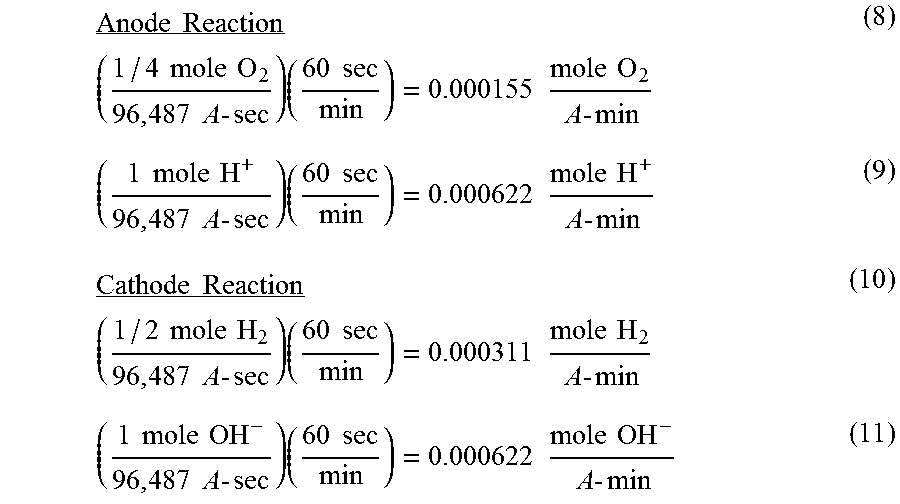
[0024] To further explain how the effluent solutions are produced by the E-CEM and the role current has on the process, the following equations (8-13) are derived using Faraday's constant. Faraday's constant is defined as the amount of electricity associated with one mole of unit charge or electron, having the value 96,487 ampere-second/equivalent. For the anode reaction (equation 3), 96,487 A sec will produce 1/4 mole O.sub.2 gas and 1 mole H.sup.+ and for the cathode reaction (equation 6), 96,487 A sec will produce 1/2 mole H.sub.2 gas and 1 mole OH.sup.-. This allows the theoretical amount of H.sup.+, OH.sup.-, H.sub.2, and O.sub.2 produced per amp/second of current passed through the electrodes to be derived as follows:
Anode Reaction _ ( 1 / 4 mole O 2 96 , 487 A - sec ) ( 60 sec min ) = 0.000155 mole O 2 A - min ( 8 ) ( 1 mole H + 96 , 487 A - sec ) ( 60 sec min ) = 0.000622 mole H + A - min ( 9 ) Cathode Reaction _ ( 1 / 2 mole H 2 96 , 487 A - sec ) ( 60 sec min ) = 0.000311 mole H 2 A - min ( 10 ) ( 1 mole OH - 96 , 487 A - sec ) ( 60 sec min ) = 0.000622 mole OH - A - min ( 11 ) ##EQU00001##
[0025] Therefore, seawater with a HCO.sub.3.sup.- concentration of 142 ppm (0.0023 M) and a flow rate of 1900 milliliters per minute will require a theoretical applied minimum current of 7.0 A to lower the pH to less than 6.0 and convert HCO.sub.3.sup.- to H.sub.2CO.sub.3 (equation 12).
( 0.0023 mole HCO 3 - Liter ) ( 1.89 Liter min ) ( 0.000622 mole H + A - min ) = 7.0 A ( 12 ) ##EQU00002##
[0026] The theoretical amount of CO.sub.2 that can be removed from the acidified seawater is 0.0023 moles per liter. The theoretical amount of H.sub.2 gas generated at 7.0 A is
( 1 / 2 mole H 2 96 , 487 A - sec ) ( 60 sec min ) ( 7.0 A ) = 0.0022 mole H 2 min ( 13 ) ##EQU00003##
[0027] Equations 8-13 describe the ability to control the removal of a weak base (HCO.sub.3.sup.-) in the form of a weak acid H.sub.2CO.sub.3 (equations 4 and 5) from seawater and its replacement with a strong base using applied current. The strong base is produced by the primary ionized species in the cathode effluent water (equation 6) that consists of OH.sup.- and Na.sup.+. The Na.sup.+ comes from the seawater or alkaline solution processed in the center compartment of the E-CEM. The Na.sup.+ ion is 8 to 10 times more concentrated in seawater than the other ions present Mg.sup.2+, Ca.sup.2+, and K.sup.+ on a mole per liter basis. (Werner et al., "Aquatic Chemistry: An introduction emphasizing chemical equilibrium in natural waters," Wiley-Interscience, New York (1970)). The cathode effluent solution or any combination of anode, cathode, and center compartment effluents become the CO.sub.2 absorption solutions for atmosphere CO.sub.2 absorption as shown in equations 14-17. (Yoo et al., "Carbon dioxide capture capacity of sodium hydroxide aqueous solution," Journal of Environmental Management, 114, 512-519 (2013)).
NaOH+CO.sub.2.fwdarw.NaHCO.sub.3 (14)
NaHCO.sub.3+NaOH.fwdarw.Na.sub.2CO.sub.2 (15)
Na.sub.2CO.sub.3+CO.sub.2+H.sub.2O.fwdarw.2NaHCO.sub.3 (16)
Overall chemical reaction: CO.sub.2+NaOH.fwdarw.NaHCO.sub.3 (17)
[0028] One mole of NaOH is capable of absorbing up to one mole of CO.sub.2. The rate and amount of CO.sub.2 absorption into NaOH is proportional to the NaOH concentration. As shown in equation 17, the CO.sub.2 is recovered from the atmosphere as NaHCO.sub.3 solution. (Yoo et al., "Carbon dioxide capture capacity of sodium hydroxide aqueous solution," Journal of Environmental Management, 114, 512-519 (2013)). This demonstrates the chemical completion of the total cycle.
[0029] FIGS. 2A and 2B demonstrate the absorption of CO.sub.2 into 0.05 molar NaOH solutions left open to the atmosphere in a five gallon bucket (11.25'' in diameter by 14.25'' high) for 385 hours. FIG. 2A shows how the pH of both 2 liter solutions decreased as a function of time and the effect of stirring the solution (open circles) on absorption was minimal. FIG. 2B provides the measured CO.sub.2 absorbed in mg/L by coulometry as a function of time in both 0.05 molar solutions. The simple NaOH solutions provide a timeframe for CO.sub.2 absorption from the atmosphere that contains only 0.7 to 0.8 mg of CO.sub.2 per liter of air. These solutions provide a means of concentrating over 1000 times that of the atmosphere as shown in FIG. 2B. The speciation diagram shown in FIG. 3 suggests that Na.sub.2CO.sub.3 is the primary product formed above pH 10.3. (Fleischer et al., "Detailed Modeling of The Chemisorption of CO.sub.2 Into NaOH In A Bubble Column," Chemical Engineering Science, 51, 1715-1724 (1996)). As CO.sub.2 is absorbed and the pH of the solution begins to fall, bicarbonate is the primary product.
[0030] FIGS. 4A and 4B demonstrate CO.sub.2 absorption into combined effluent from the E-CEM process. Key West seawater was processed through a laboratory E-CEM unit at a flow rate of 140 mL/min and deionized water flowrate to the anode and cathode of 14 mL/min and 12 mL/min. The initial pH of the seawater was 8.03 and was reduced to 3.6. The effluent solutions were collected at a pH of 3.6 for approximately 20 minutes. The acidified seawater was sparged with nitrogen. The solutions were combined and measured at an initial pH of 10.5 (FIG. 4A) and CO.sub.2 content of 9.66 mg/L (FIG. 4B). Samples were collected over twenty two hours and it was found that the pH of the combined effluents reduced to as low as 9.5 (FIG. 4A) and the [CO.sub.2].sub.T measured as high as 33.41 mg/L.
[0031] To determine the effect surface area has on CO.sub.2 re-equilibration in E-CEM effluent, Key West seawater was processed through a larger scale E-CEM at 0.5 gpm and electrode flowrates up to 0.042 gpm. The effluent solutions were collected and combined under three separate experimental conditions. In the first experiment the initial pH of the seawater before processing was 8.3. The E-CEM effluent streams were collected for 160 minutes. This equates to five thirty-minute polarity cycles. A polarity cycle is defined by the length of time an electrode is functioning as an anode/or cathode before the polarity in the module is switched and the electrode acting as the anode/or cathode becomes the cathode/or anode. Polarity switching is a common practice in the Electrodialysis Reversal (EDR) process to desalinate brackish ground and surface waters and it is designed into this system to provide electrode regeneration at regular intervals called polarity cycles. (Dermentzis, "Continuous electrodeionization through electrostatic shielding," Electrochim. Acta, 53, 2953-2962 (2008)).
[0032] For over 160 minutes the seawater effluent was sparged with nitrogen as it exited the E-CEM. The processed streams were collected in a 120''.times.72''.times.18'' rubber pool and allowed to re-equilibrate with the atmosphere for sixty-nine hours. Over the course of sixty-nine hours, 5 mL samples were collected twice a day to measure CO.sub.2 concentration by coulometry and pH. FIGS. 5A and 5B show that the pH and % CO.sub.2 of the combined processed water measured 9.3 and 19.0% (Large Pool filled black circles). After sixty-nine hours the [CO.sub.2].sub.T content increased to 55% and the pH dropped to 9.0.
[0033] In the second experiment effluents processed by the E-CEM were collected in three separate pools 5 feet in diameter (Pool 1 closed squares, Pool 2 closed triangles, Pool 3 open squares). The first and third pool collected E-CEM effluents over 160 minutes. The second pool was filled with effluents collected over 80 minutes. The third pool had a circulating pump that recirculated the water at 75 gph. The processed seawater effluent in each pool was sparged with nitrogen as it exited the E-CEM. The initial seawater pH before processing measured 7.8. FIGS. 5A and 5B show the combined effluent pH initially measured approximately 9 for each pool. Samples were collected from each pool once a day over 219 hours and the pH decreased to 8.4 for Pools 1 and 3 and to 7.9 for Pool 2. The % CO.sub.2 for the combined effluents initially measured 16.7% Pool 1, 11.1% Pool 2, and 7.7% Pool 3. These values increased over 219 hours to 66.3%, 71.9%, and 69.0%.
[0034] The third experiment collected effluent from the E-CEM for two polarity cycles in a 32 gallon bucket that was 1.6 feet in diameter. This container had the smallest surface to volume ratio of all three experiments. The initial pH and % CO.sub.2 of the combined effluents from the E-CEM measured 9.2 and 7.7%. The final pH and % CO.sub.2 measured 8.5 and 29.1% after 219 hours.
[0035] Comparing all three experiments in FIGS. 5A and 5B shows that the Large Pool (Large Pool filled black circles) had the fastest rate of CO.sub.2 re-equilibration based on the slope. Pool 2 recorded the most % CO.sub.2 recovery at 71.9%. Finally the % CO.sub.2 re-equilibrated for the bucket and the large pool highlight the role surface to volume ratio has on re-equilibration of CO.sub.2 from the atmosphere into E-CEM effluent.
[0036] Since the primary ionized species in the cathode effluent water (equation 6) consist of OH.sup.- and Na.sup.+, the catholyte effluent solution was collected separately and the pH measured over two twenty minute polarity cycles. Table 1 summarizes the pH of the effluent catholyte as 60 gpd of freshwater was fed to each electrode compartment during each cycle. The average pH of the catholyte solution measured 12.5 over both polarity cycles. The concentration of NaOH at these pH levels is calculated to be 0.038 mol/L. A portion of the catholyte solution at this high pH could be used to capture CO.sub.2 from the atmosphere while the rest is used to mix with the effluent seawater to bring the total pH to 7 or greater. To enhance absorption of CO.sub.2 from the atmosphere, the catholyte was passed through a column and treated with air at a flow rate of 1 lpm and a space time of 2 minutes. Under these conditions the pH dropped to an average of 12.32 (Table 1).
TABLE-US-00001 TABLE 1 Catholyte Measured Every Five Minutes at 60 gpd Flowrate to Each Electrode Polarity A Polarity B pH pH Min Amp pH w/air pH w/air 20 30.0 12.57 12.36 12.60 12.51 15 30.0 12.45 12.34 12.58 12.43 10 30.0 12.49 12.29 12.57 12.17 5 30.0 12.43 12.32 12.55 12.39 0 30.0 12.44 12.24 12.57 12.10
[0037] When the flowrates to the electrodes were lowered to 30 gpd, Table 2 shows the final pH of the catholyte solution measured an average of 13.5 which equates to 0.5 mol/L of NaOH available for absorption of CO.sub.2 from the atmosphere. At these lower electrode flowrates the catholyte solution is more concentrated causing an increase in pH by approximately 1 pH unit. At these flowrates the catholyte was passed through a PVC column and treated with air at a flow rate of 4 lpm at a space time of 16 minutes. The pH of the catholyte dropped to an average of 13.2.
[0038] These experiments highlight the significance that electrode flowrate has on the pH of the effluent catholyte stream and NaOH concentration of the stream. The air bubbling results suggest that more detailed kinetic studies of dilute CO.sub.2 absorption into basic hydroxide solutions are needed.
TABLE-US-00002 TABLE 2 Catholyte Collected in Five Gallon Bucket at 30 gpd Flowrate to Each Electrode pH pH w/air Polarity A 13.51 13.21 Polarity B 13.46 13.23
[0039] As shown by these experiments, the higher the catholyte flowrate into the E-CEM, the lower the pH of the effluent catholyte solution. Also, the higher current applied to the E-CEM, the higher the pH of the effluent catholyte solution.
[0040] The above descriptions are those of the preferred embodiments of the invention. Various modifications and variations are possible in light of the above teachings without departing from the spirit and broader aspects of the invention. It is therefore to be understood that the claimed invention may be practiced otherwise than as specifically described. Any references to claim elements in the singular, for example, using the articles "a," "an," "the," or "said," is not to be construed as limiting the element to the singular.
* * * * *
D00000
D00001
D00002
D00003
D00004
D00005
XML
uspto.report is an independent third-party trademark research tool that is not affiliated, endorsed, or sponsored by the United States Patent and Trademark Office (USPTO) or any other governmental organization. The information provided by uspto.report is based on publicly available data at the time of writing and is intended for informational purposes only.
While we strive to provide accurate and up-to-date information, we do not guarantee the accuracy, completeness, reliability, or suitability of the information displayed on this site. The use of this site is at your own risk. Any reliance you place on such information is therefore strictly at your own risk.
All official trademark data, including owner information, should be verified by visiting the official USPTO website at www.uspto.gov. This site is not intended to replace professional legal advice and should not be used as a substitute for consulting with a legal professional who is knowledgeable about trademark law.