Water Electrolyzers Employing Anion Exchange Membranes
Masel; Richard I. ; et al.
U.S. patent application number 15/922883 was filed with the patent office on 2019-03-21 for water electrolyzers employing anion exchange membranes. The applicant listed for this patent is Dioxide Materials, Inc.. Invention is credited to Zengcai Liu, Richard I. Masel.
| Application Number | 20190085471 15/922883 |
| Document ID | / |
| Family ID | 65719931 |
| Filed Date | 2019-03-21 |
| United States Patent Application | 20190085471 |
| Kind Code | A1 |
| Masel; Richard I. ; et al. | March 21, 2019 |
Water Electrolyzers Employing Anion Exchange Membranes
Abstract
Water electrolyzers comprises an anode comprising a quantity of anode catalyst, a cathode comprising a quantity of cathode catalyst with an inlet for introducing a cathode reactant thereto, an anion-conducting polymer electrolyte membrane interposed between said anode and said cathode, and a source of electrical energy that applies a voltage between the anode and cathode. At least one of said anode catalyst or said cathode catalyst comprises a metal or metal alloy having a surface area of at least 12 m.sup.2/gm. Water electrolyzers preferably employ base metal catalysts and an anion-conducting polymeric membrane with a resistance below 0.3 ohm-cm.sup.2 and a base metal catalyst with a surface area of at least 12 m.sup.2/mg.
| Inventors: | Masel; Richard I.; (Boca Raton, FL) ; Liu; Zengcai; (Boca Raton, FL) | ||||||||||
| Applicant: |
|
||||||||||
|---|---|---|---|---|---|---|---|---|---|---|---|
| Family ID: | 65719931 | ||||||||||
| Appl. No.: | 15/922883 | ||||||||||
| Filed: | March 15, 2018 |
Related U.S. Patent Documents
| Application Number | Filing Date | Patent Number | ||
|---|---|---|---|---|
| 15406909 | Jan 16, 2017 | 9982353 | ||
| 15922883 | ||||
| 15400775 | Jan 6, 2017 | 9849450 | ||
| 15406909 | ||||
| 15090477 | Apr 4, 2016 | 9580824 | ||
| 15400775 | ||||
| 14704935 | May 5, 2015 | 9370773 | ||
| 15090477 | ||||
| PCT/US2015/014328 | Feb 3, 2015 | |||
| 14704935 | ||||
| PCT/US2015/026507 | Apr 17, 2015 | |||
| 14704935 | ||||
| 62066823 | Oct 21, 2014 | |||
| 62066823 | Oct 21, 2014 | |||
| Current U.S. Class: | 1/1 |
| Current CPC Class: | C25B 9/10 20130101; C25B 1/10 20130101; C25B 11/04 20130101; C25B 9/08 20130101; C25B 11/0447 20130101 |
| International Class: | C25B 1/10 20060101 C25B001/10; C25B 11/04 20060101 C25B011/04; C25B 9/10 20060101 C25B009/10 |
Goverment Interests
STATEMENT OF GOVERNMENT INTEREST
[0004] This invention was made, at least in part, with U.S. government support under ARPA-E Contract No. DE-AR-0000684. The government has certain rights in the invention.
Claims
1. A water electrolyzer comprising: (a) an anode comprising a quantity of anode catalyst; (b) a cathode comprising a quantity of cathode catalyst, said cathode having an inlet for introducing a cathode reactant thereto; (c) an anion-conducting polymer electrolyte membrane interposed between said anode and said cathode; and (d) a source of electrical energy that applies a voltage between the anode and cathode, wherein at least one of said anode catalyst or said cathode catalyst comprises a metal or metal alloy having a surface area of at least 12 m.sup.2/gm.
2. The water electrolyzer of claim 1, wherein said cathode catalyst comprises a base metal.
3. The water electrolyzer of claim 2, wherein said cathode catalyst comprises a metal or metal alloy with a surface area of at least 20 m.sup.2/gm.
4. The water electrolyzer of claim 3, wherein said cathode catalyst comprises a metal or metal alloy with a surface area of at least 30 m.sup.2/gm.
5. The water electrolyzer of claim 4, wherein said cathode catalyst comprises a metal or metal alloy with a surface area of at least 50 m.sup.2/gm.
6. The water electrolyzer of claim 2, wherein said cathode catalyst comprises nickel or a nickel alloy.
7. The water electrolyzer of claim 2, wherein said cathode catalyst comprises a porous metal.
8. The water electrolyzer of claim 7, wherein said cathode catalyst comprises a spongy metal.
9. The water electrolyzer of claim 8, wherein said cathode catalyst comprises at least one of nickel sponge or Raney nickel.
10. The water electrolyzer of claim 2, wherein said anion-conducting polymer electrolyte membrane has a resistance below 1 ohm-cm.sup.2 in 1 M KOH at 60.degree. C.
11. The water electrolyzer of claim 10, wherein said anion-conducting polymer electrolyte membrane has a resistance below 0.3 ohm-cm.sup.2 in 1 M KOH at 60.degree. C.
13. The water electrolyzer of claim 10, wherein said anion-conducting polymer electrolyte membrane has a resistance below 0.1 ohm-cm.sup.2 in 1 M KOH at 60.degree. C.
14. The water electrolyzer of claim 3, wherein said cathode catalyst comprises a catalyst layer on at least one of: (a) said an anion-conducting polymer electrolyte membrane; (b) a gas diffusion layer; (c) a metal fiber paper; and (d) a metal grid or screen.
15. The water electrolyzer of claim 14, wherein said catalyst layer is no more than 80 nm thick.
16. The water electrolyzer of claim 15, wherein said catalyst layer is no more than 60 nm thick.
17. The water electrolyzer of claim 15, wherein said catalyst layer has a thickness of 15-20 nm.
18. The water electrolyzer of claim 1, wherein said cathode reactant comprises water.
Description
CROSS-REFERENCE TO RELATED APPLICATIONS
[0001] The present application is a continuation-in-part of U.S. patent application Ser. No. 15/406,909 filed on Jan. 16, 2017, entitled "Water Electrolyzers". The '909 application is, in turn, a continuation-in-part of U.S. patent application Ser. No. 15/400,775 filed on Jan. 6, 2017, entitled "Ion-Conducting Membranes". The '775 application is, in turn, a continuation-in-part of U.S. patent application Ser. No. 15/090,477 filed on Apr. 4, 2016, also entitled "Ion-Conducting Membranes". The '477 application is, in turn, a continuation-in-part of U.S. patent application Ser. No. 14/704,935 filed on May 5, 2015 (now U.S. Pat. No. 9,370,773 issued on Jun. 6, 2016), also entitled "Ion-Conducting Membranes". The '935 application was, in turn, a continuation-in-part of International Application No. PCT/US2015/014328, filed on Feb. 3, 2015, entitled "Electrolyzer and Membranes". The '328 international application claimed priority benefits from U.S. provisional patent application Ser. No. 62/066,823, filed on Oct. 21, 2014.
[0002] The '935 application was also a continuation-in-part of International Application No. PCT/US2015/026507, filed on Apr. 17, 2015, entitled "Electrolyzer and Membranes". The '507 international application also claimed priority benefits from U.S. provisional patent application Ser. No. 62/066,823 filed Oct. 21, 2014.
[0003] The '909 patent application, the '775 application, the '477 application, the '935 application, the '823 provisional application, and the '328 and '507 international applications are each hereby incorporated by reference herein in their entirety.
FIELD OF THE INVENTION
[0005] The field of the invention is electrochemistry. The devices, systems and compositions described herein involve the electrolysis of water.
BACKGROUND OF THE INVENTION
[0006] The electrolysis of water is presently used as a source of hydrogen in, for example, hydrogen filling stations and chemical plants, and as a way of storing excess renewable energy using a technology called "power to gas".
[0007] There are two main types of low temperature electrolyzers: proton exchange membrane (PEM) electrolyzers and alkaline water electrolyzers. PEM electrolyzers are able to operate at current densities around 1 A/cm.sup.2 at cell voltages less than 2 V and can be turned on and off quickly. Unfortunately, PEM electrolyzers typically require the use of precious metal catalysts, such as platinum or iridium. This is a significant economic limitation.
[0008] In contrast, the present generation of alkaline water electrolyzers do not require the use of precious metals; instead, base metal catalysts can be used. Unfortunately, the present generation of alkaline water electrolyzers typically operate at lower current densities than PEM electrolyzers. This raises the capital equipment cost.
[0009] For example, U.S. Pat. No. 4,445,994 discloses that alkaline water electrolyzers operate at 200-300 mA/cm.sup.2 (0.2-0.3 A/cm.sup.2) at cell potentials of 1.8-2 V. The '994 patent also discloses that obtain currents of 1 A/cm.sup.2 can be obtained by increasing the cell temperature to 110.degree. C., but as pointed out in U.S. Patent Application Publication No. US2016/02375781A1, the upper temperature limit of a practical alkaline water electrolyzer is 80-90.degree. C., since one observes excessive corrosion above 80-90.degree. C. in these high pH systems (for example, 5 M KOH electrolyte.) Recently, U.S. Patent Application Publication No. US2016/0312371A1 discloses an anion exchange membrane (AEM) electrolyzer design that can obtain 40 A/dm.sup.2=0.4 A/cm.sup.2 at 80.degree. C. and 1.9 V. This is a significant improvement, but still below the performance of a PEM electrolyzer.
[0010] AEM water electrolyzers have also been started to be discussed in the literature as replacements for conventional alkaline water electrolyzers. A recent review by Vincent and Bessarabov (Renewable and Sustainable Energy Reviews, volume 81, pages 1690-1704 (2018)) states that "few research articles (less than 20) have been published on AEM water electrolysis."
[0011] It has generally been assumed, without substantial evidence, that the catalyst that has already been shown to have the highest activity in a conventional alkaline water electrolyzer will also have the highest activity in an AEM water electrolyzer.
[0012] The data presented herein shows that catalysts reported to be optimal for a conventional alkaline water electrolyzer show only modest performance in an AEM water electrolyzer, while catalysts that show modest performance in a conventional alkaline water electrolyzer show superior performance in an AEM water electrolyzer.
SUMMARY OF THE INVENTION
[0013] The present water electrolyzers employing anion exchange membranes provide an alkaline electrolyzer design that employs cathode catalysts that are improved for use in an AEM water electrolyzer. The electrolyzer comprises: [0014] (a) an anode comprising a quantity of anode catalyst; [0015] (b) a cathode comprising a quantity of cathode catalyst, said cathode having an inlet for introducing a cathode reactant thereto; [0016] (c) an anion exchange membrane interposed between said anode and said cathode; and [0017] (d) a source of electrical energy that applies a voltage between the anode and cathode. At least one of the anode catalyst and the cathode catalyst comprises a metal or metal alloy having a surface area of at least 12 m.sup.2/gm.
[0018] The cathode catalyst preferably comprises a metal or metal alloy with a surface area of at least 20 m.sup.2/gm. More preferably, the cathode catalyst comprises a metal or metal alloy with a surface area of at least 30 m.sup.2/gm. Most preferably, the cathode catalyst comprises a metal or metal alloy with a surface area of at least 50 m.sup.2/gm.
[0019] Preferably, the cathode catalyst comprises nickel or a nickel alloy, most preferably at least one of nickel sponge or Raney nickel. The cathode catalyst can comprise a porous metal and/or a spongy metal.
[0020] Preferably, the anion-conducting polymer electrolyte membrane has a resistance below 1 ohm-cm.sup.2 in 1 M KOH at 60.degree. C., more preferably the ion conducting polymer has a resistance below 0.3 ohm-cm.sup.2 most preferably the ion conducting polymer has a resistance below 0.1 ohm-cm.sup.2.
[0021] In the foregoing water electrolyzer, the cathode catalyst preferably comprises a catalyst layer on at least one of:
[0022] (a) said an anion-conducting polymer electrolyte membrane;
[0023] (b) a gas diffusion layer;
[0024] (c) a metal fiber paper; or
[0025] (d) a metal grid or screen.
The catalyst layer is preferably no more than 80 nm thick, more preferably no more than 60 nm thick, and even more preferably about 15-20 nm thick.
BRIEF DESCRIPTION OF THE DRAWINGS
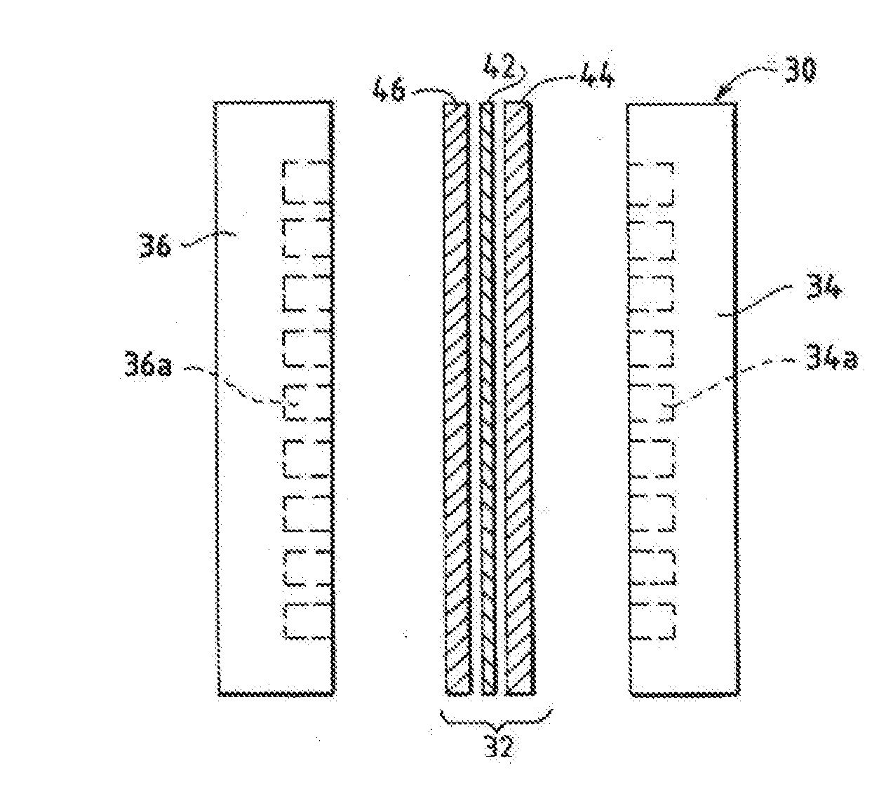
[0026] FIG. 1 is an exploded side view of a fuel cell hardware assembly including a membrane electrode assembly interposed between two fluid flow field plates having reactant flow channels formed in the major surfaces of the plates facing the electrodes.
[0027] FIG. 2 is an exploded side view of a fuel cell hardware assembly including a membrane electrode assembly having integral reactant flow channels interposed between two separator layers.
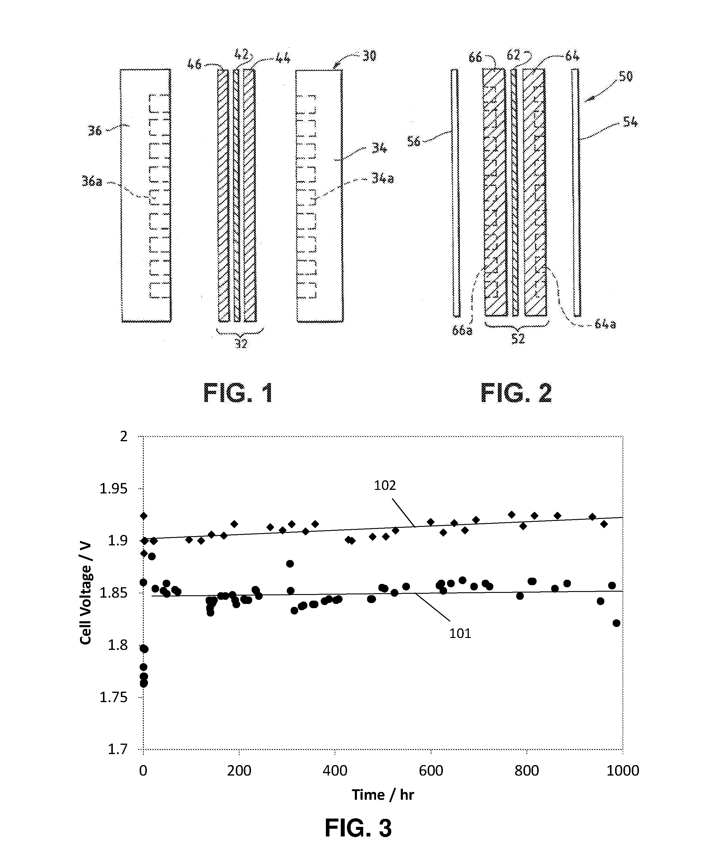
[0028] FIG. 3 is a plot of cell voltage as a function of time for the test described in Specific Example 1. Line 101 is for the cell with the Raney nickel catalyst, line 102 is for the cell with the NiFeCo catalyst.
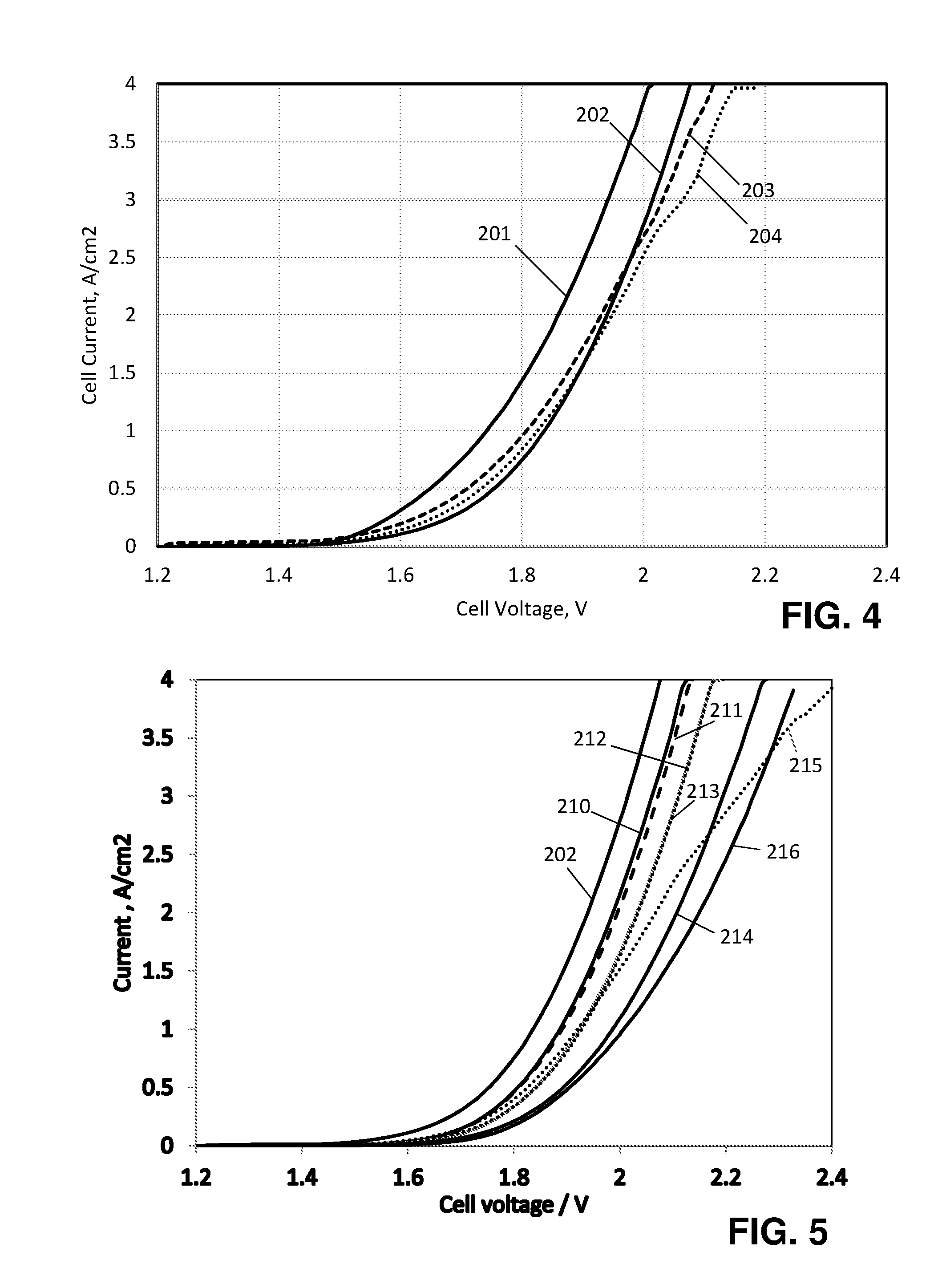
[0029] FIG. 4 is a plot of cell current as a function of cell voltage at (201) the start of the experiment, (202) after 24.8 hours, (203) after 357 hours, and (204) after 530 hours.
[0030] FIG. 5 is a plot of cell current as a function of cell voltage after 24 hours with a nickel fiber cathode coated with (202) Raney nickel cathode catalyst, (210) NiFeCo cathode catalyst, (211) Ni.sub.8Fe.sub.2 cathode catalyst, (212) FeCoBeSi cathode catalyst, (213) NiMoBi cathode catalyst, (214) Ni.sub.80Mo.sub.20 cathode catalyst, (215) NiMo/C cathode catalyst, and (216) nickel fiber paper with no added catalyst.
DETAILED DESCRIPTION OF ILLUSTRATIVE EMBODIMENT(S)
[0031] It is understood that the process is not limited to the particular methodology, protocols and reagents described herein, as these can vary as persons familiar with the technology involved here will recognize. It is also to be understood that the terminology used herein is used for the purpose of describing particular embodiments only and is not intended to limit the scope of the process. It also is to be noted that as used herein and in the appended claims, the singular forms "a", "an", and "the" include the plural reference unless the context clearly dictates otherwise. Thus, for example, a reference to "a linker" is a reference to one or more linkers and equivalents thereof known to those familiar with the technology involved here. Similarly, the phrase "and/or" is used to indicate one or both stated cases can occur, for example, A and/or B includes (A and B) and (A or B).
[0032] Unless defined otherwise, technical and scientific terms used herein have the same meanings as commonly understood by one of ordinary skill in the art to which the process pertains. The embodiments of the process and the various features and advantageous details thereof are explained more fully with reference to the non-limiting embodiments and/or illustrated in the accompanying drawings and detailed in the following description. It should be noted that the features illustrated in the drawings are not necessarily drawn to scale, and features of one embodiment can be employed with other embodiments as a person familiar with the technology here would recognize, even if not explicitly stated herein.
[0033] Any numerical value ranges recited herein include all values from the lower value to the upper value in increments of one unit, provided that there is a separation of at least two units between any lower value and any higher value. As an example, if it is stated that the concentration of a component or value of a process variable such as, for example, size, angle size, pressure, time and the like, is, for example, from 1 to 98, specifically from 20 to 80, more specifically from 30 to 70, it is intended that values such as 15 to 85, 22 to 68, 43 to 51, 30 to 32, and the like, are expressly enumerated in this specification. For values which are less than one, one unit is considered to be 0.0001, 0.001, 0.01 or 0.1 as appropriate. These are only examples of what is specifically intended and all possible combinations of numerical values between the lowest value and the highest value are to be treated in a similar manner.
[0034] Moreover, provided immediately below is a "Definitions" section, where certain terms related to the process are defined specifically. Particular methods, devices, and materials are described, although any methods and materials similar or equivalent to those described herein can be used in the practice or testing of the process.
Definitions
[0035] The term "anion exchange membrane" or "anion-conducting polymer electrolyte membrane" as used here refers to membranes comprising polymer electrolytes having multiple covalently attached positively charged groups.
[0036] The term "cation exchange membrane" as used here refers to membranes comprising polymer electrolytes having multiple covalently attached negatively charged groups such as the perfluorosulfonic acid polymer available under the trade designation NAFION from E. I. du Pont de Nemours and Company (DuPont) of Wilmington, Del.
[0037] The term "polymer electrolyte membrane" as used here refers to both cation exchange membranes and anion exchange membranes.
[0038] The term "anion exchange membrane electrolyzer" or "AEM water electrolyzer" as used here refers to an electrolyzer with an anion-conducting polymer electrolyte membrane separating the anode from the cathode.
[0039] The term "alkaline water electrolyzer" or "conventional alkaline water electrolyzer" as used here refers to an electrolyzer with a porous membrane separating the anode and cathode, where the pores are at least 0.05 .mu.m in diameter. Typically, the pores are about 0.15 .mu.m in diameter.
[0040] The term "Hydrogen Evolution Reaction," also called "HER," as used here refers to the electrochemical reaction 2H++2e.sup.-.fwdarw.H.sub.2.
[0041] The term "MEA" as used here refers to a membrane electrode assembly.
[0042] The term "Millipore water" is water that is produced by a Millipore filtration system with a resistivity of at least 18.2 megaohm-cm.
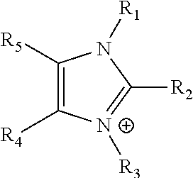
[0043] The term "imidazolium" as used here refers to a positively charged ligand containing an imidazole group. This includes a bare imidazole or a substituted imidazole. Ligands of the form:
##STR00001##
where R.sub.1-R.sub.5 are each independently selected from hydrogen, halides, linear alkyls, branched alkyls, cyclic alkyls, heteroalkyls, aryls, heteroaryls, alkylaryls, heteroalkylaryls, and polymers thereof, such as the vinyl benzyl copolymers described herein, which are specifically included.
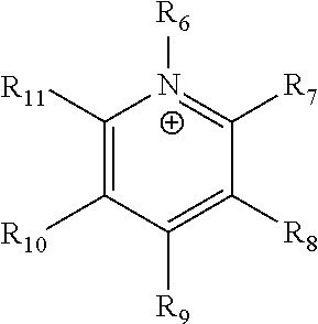
[0044] The term "pyridinium" as used here refers to a positively charged ligand containing a pyridine group. This includes a bare pyridine or a substituted pyridine. Ligands of the form:
##STR00002##
where R.sub.6-R.sub.11 are each independently selected from hydrogen, halides, linear alkyls, branched alkyls, cyclic alkyls, heteroalkyls, aryls, heteroaryls, alkylaryls, heteroalkylaryls, and polymers thereof, such as the vinyl benzyl copolymers described herein, which are specifically included.
[0045] The term "phosphonium" as used here refers to a positively charged ligand containing phosphorous. This includes substituted phosphorous ligands of the form:
P.sup.+(R.sub.12R.sub.13R.sub.14R.sub.15)
where R.sub.12-R.sub.15 are each independently selected from hydrogen, halides, linear alkyls, branched alkyls, cyclic alkyls, heteroalkyls, aryls, heteroaryls, alkylaryls, heteroalkylaryls, and polymers thereof, such as the vinyl benzyl copolymers described herein, which are specifically included.
[0046] The term "positively charged cyclic amine" as used here refers to a positively charged ligand containing a cyclic amine. This specifically includes imidazoliums, pyridiniums, pyrazoliums, pyrrolidiniums, pyrroliums, pyrimidiums, piperidiniums, indoliums, triaziniums, and polymers thereof, such as the vinyl benzyl copolymers described.
[0047] The term "simple amine" as used here refers to a species of the form
N(R.sub.16R.sub.17R.sub.18)
wherein R.sub.16-R.sub.18 are each independently selected from hydrogen, linear alkyls, branched alkyls, cyclic alkyls, heteroalkyls, aryls, heteroaryls, alkylaryls, and heteroalkylaryls, but not polymers.
[0048] The term "precious metal" as used here refers to one or more of Ru, Rh, Pd, Ag, Re, Os, Ir, Pt, and Au.
[0049] The term "base metal catalyst" as used here refers to a catalyst that is substantially free of precious metals.
[0050] The term "porous metal" as used here refers to a metal with a pore volume greater than 1% of the total volume of the material.
[0051] The term "spongy metal" as used here refers to a metal with a pore volume greater than 10% of the total volume of the material. Spongy metals specifically include sponge iron (also called direct reduced iron), titanium sponge, copper sponge, cobalt sponge, platinum sponge, palladium sponge, nickel sponge, Raney nickel and all the catalysts listed in the Johnson Matthey publication "Sponge Metal Catalysts" (http://www.jmprotech.com/images-uploaded/files/72052%20Sponge%20Metal%20- brochure.pdf; last accessed on Mar. 15, 2018), Nikko-Rica publication "Sponge Metal Catalysts" (http://www.nikko-rica.co.jp/en/business/s_metal/; last accessed on Mar. 15, 2018), and Kawaken Fine Chemicals publication "Sponge Metal Catalysts" (https://www.kawakenfc.co.jp/en/products/fine/index.php/search?list=1&cel- l003=Sponge+Metal+Catalyst&cell030=&keyword=; last accessed on Mar. 15, 2018).
[0052] The term "intrinsic activity" as used here refers to the catalytic activity of a given catalyst, measured as the current per unit area at a fixed voltage, divided by the surface area per gm of the catalyst.
Specific Description
[0053] FIG. 1 illustrates a fuel cell hardware assembly 30, which includes a membrane electrode assembly 32 interposed between rigid flow field plates 34 and 36, typically formed of graphite or a graphite composite material. Membrane electrode assembly 32 consists of a polymer electrolyte (ion exchange) membrane 42 interposed between two electrodes, namely, anode 44 and cathode 46. Anode 44 and cathode 46 are typically formed of porous electrically conductive sheet material, such as carbon fiber paper, and have planar major surfaces. Electrodes 44 and 46 have a thin layer of catalyst material disposed on their major surfaces at the interface with membrane 42 to render them electrochemically active.
[0054] As shown in FIG. 1, anode flow field plate 34 has at least one open faced channel 34a engraved, milled or molded in its major surface facing membrane 42. Similarly, cathode flow field plate 36 has at least one open faced channel 36a engraved, milled or molded in its major surface facing membrane 42. When assembled against the cooperating surfaces of electrodes 44 and 46, channels 34a and 36a form the reactant flow field passages for the anode reactant stream (if any) and cathode reactant stream (comprising water, in the case of the present water electrolyzer), respectively.
[0055] Turning to FIG. 2, a fuel cell hardware assembly 50 employs a membrane electrode assembly 52 having integral reactant fluid flow channels. Fuel cell hardware assembly 50 includes membrane electrode assembly 52 interposed between lightweight separator layers 54 and 56, which are substantially impermeable to the flow of reactant fluid therethrough. Membrane electrode assembly 52 consists of a polymer electrolyte (ion exchange) membrane 62 interposed between two electrodes, namely, anode 64 and cathode 66. Anode 64 and cathode 66 are formed of porous electrically conductive sheet material, such as carbon fiber paper. Electrodes 64 and 66 have a thin layer of catalyst material disposed on their major surfaces at the interface with membrane 62 to render them electrochemically active.
[0056] As shown in FIG. 2, anode 64 has at least one open faced channel 64a formed in its surface facing away from membrane 62. Similarly, cathode 66 has at least one open faced channel 66a formed in its surface facing away from membrane 62. When assembled against the cooperating surfaces of separator layers 54 and 56, channels 64a and 66a form the reactant flow field passages for the anode and cathode reactant streams, respectively.
[0057] During operation, reactants or a solution containing reactants is fed into the cell. Then a voltage is applied between the anode and the cathode, to promote an electrochemical reaction.
[0058] Without further elaboration, it is believed that persons familiar with the technology involved here using the preceding description can utilize the claimed electrolyzer to full extent. The following examples are illustrative only and are not meant to be an exhaustive list of all possible embodiments, applications or modifications of the claimed electrolyzer.
Specific Example 1
[0059] The objective of this example was to demonstrate an anion exchange membrane electrolyzer with a base metal cathode catalyst that is more active than the typical commercial catalysts used in conventional alkaline electrolyzers.
[0060] The cell contained: [0061] (a) an anode comprising a quantity of anode catalyst, said anode having an anode reactant introduced thereto via at least one anode reactant flow channel; [0062] (b) a cathode comprising a quantity of cathode catalyst, said cathode having a cathode reactant introduced thereto via at least one cathode reactant flow channel; [0063] (c) an anion conducting polymeric membrane interposed between said anode and said cathode; and [0064] (d) a source of electrical energy that applies a voltage between the anode and cathode,
[0065] in which the cathode catalyst comprises a porous metal.
[0066] A membrane was prepared as set forth below.
[0067] The first inhibitor-free 4-vinylbenzyl chloride (VBC) was prepared by adding a volume V of VBC, (Sigma-Aldrich, Saint Louis, Mo.) and a volume equal to V/4 of 4% aqueous sodium hydroxide into a separatory funnel, followed by agitating the funnel to mix the water and VBC, then decanting the VBC. The process was repeated five times until the water layer did not show visible color change. The procedure was repeated using pure water instead of sodium hydroxide solution until the water layer pH was neutral. Washed VBC was placed into a freezer overnight before weighing to convert residual water to mainly ice, and the ice was then separated from VBC by filtration or decantation.
[0068] Next, inhibitor-free styrene was prepared by feeding styrene (Sigma-Aldrich) through a 60 mL syringe (HSW, Tuttlingen, Germany) packed with Sigma-Aldrich 311340 Inhibitor remover.
[0069] Poly(4-vinylbenzyl chloride-co-styrene) was then synthesized by heating a solution of inhibitor-free styrene (Sigma-Aldrich) (172.3 g, 1.65 mol) and 4-vinylbenzyl chloride (Sigma-Aldrich) (143.1 g, 0.94 mol) in chlorobenzene (Sigma-Aldrich) (250 g) at 60-65.degree. C. in an oil bath for 22 hours under nitrogen gas with AIBN (.alpha.,.alpha.'-Azoisobutyronitrile, Sigma-Aldrich) (2.9635 g, 0.94 wt % based on the total monomers weight) as initiator. The copolymer was precipitated in methanol, then washed thoroughly and dried at 60.degree. C. overnight.
[0070] Next 1,2,4,5-tetramethylimidazole (TCI, Japan) (3.700 g, 0.0298 mol), above-synthesized poly(4-VBC-co-St) (10 g), anhydrous ethanol (17 g, Sigma-Aldrich), anhydrous toluene (12.5 g, Sigma-Aldrich), divinylbenzene (DVB) (0.2 g, 0.00154 mol in 1 g ethanol) and AIBN (0.00301 g in 0.97 g ethanol) were mixed under the protection of nitrogen flow. The mixture was stirred and heated to 78.degree. C. for about 1 hour. When the solution turned clear, the reaction temperature was decreased to 55.degree. C. and maintained for 71 hours to obtain the polymer.
[0071] The membranes were prepared by casting the polymer solutions prepared above directly onto a polyethylene terephthalate (PET) liner. The thickness of the solution on the liner was controlled by a film applicator (MTI Corporation, Richmond, Calif.) with an adjustable doctor blade. The membranes were then dried in a vacuum oven with temperature increased to 70.degree. C. and held for 1 hour. After one more hour in the vacuum oven with temperature slowly decreased, the membrane was taken out of the oven and put inside a 1 M KOH solution overnight, during which time the membrane fell from the liner. The KOH solution was changed twice, each with a couple of hours of immersion, such that the membrane chloride ions were substantially completely exchanged, so that the membranes were converted into the hydroxide form. This also made the polymer insoluble in most solvents, suggesting that some residual vinyl benzyl chlorides and/or the hydroxides from the soaking solution have reacted with some other species to form something insoluble.
[0072] NMR spectroscopy of the polymer solution from before membrane casting indicates that in the polymer about 40% of the VBC did not react with the tetramethylimidazole. The weight of the VBC that did not react with the tetramethylimidazole represented about 14% of the total weight of the membrane. Thus, the KOH-soaked, ion exchanged membrane is a terpolymer of styrene, vinylbenzyl chloride (and/or hydroxide) and vinylbenzyl tetramethylimidazolium, with negative counterions of hydroxide (and perhaps traces of residual chloride.)
[0073] A cathode was prepared as follows: 200 mg of W.R. Grace Raney nickel purchased from Sigma Aldrich (St Louis, Mo.) #3202 was ball milled for 10 minutes in a DECO 0.4 L ball mill. 100 mg of the catalyst was suspended in 2 ml of isopropanol, 1 ml of deionized water and 0.2 ml of 5% dispersion of ionomer available under the trade designation NAFION (DuPont.) The mixture was ultrasonicated in a water bath for 10 minutes. The cathode ink was spray coated onto a 5 cm.times.5 cm nickel fiber paper to form a catalyst layer that was about 20 nm thick. The electrode was dried at 80.degree. C. for 20 minutes in an oven and cut into 4 pieces of 2.5 cm.times.2.5 cm for testing. The catalyst loading was about 3 mg/cm.sup.2.
[0074] The anode for the oxygen evolution reaction was prepared in a similar way using as received NiFeOx nanoparticles (U.S. Research Nanomaterials, Inc.) instead of Raney nickel. The catalyst ink was spray coated onto 6 cm.times.6 cm stainless steel fiber cloth (AISI 316L-WNR, Bekaert, Zwevegem, Belgium). The electrode was dried at 80.degree. C. for 20 minutes in an oven and cut into 4 pieces of 3 cm.times.3 cm for testing. The actual loading was about 2 mg/cm.sup.2.
[0075] The membrane prepared above was sandwiched between the Raney nickel cathode and NiFeOx anode as described above and mounted into 5 cm.sup.2 fuel cell hardware (Fuel Cell Technologies, Albuquerque, N. Mex.). The anode graphite flow field was replaced with a Ni flow field to alleviate the carbon corrosion in the anode. 1 M KOH was fed at 2 ml/min to the cathode and anode chambers from the same container with the chamber outputs going to two separation units, which units were used to separate gas from liquid before the recirculating liquid re-entered the main container. The cell was heated and maintained at 60.degree. C. with a PID (proportional-integral-derivative) controller. The cell was held at constant current density of 1 A/cm.sup.2 and the cell voltage was monitored.
[0076] Line 101 in FIG. 3 shows the results of the experiments. Notice that the cell with a Raney nickel catalyst maintained 1 A/cm.sup.2 at 60.degree. C. at about 1.85 volts for 1000 hours.
[0077] FIG. 4 shows how the current in the cell varied with the applied voltage during the experiments above. Line 201 is the initial performance, while lines 202, 203 and 204 show the performance after 24.8, 357 and 530 hours. Initially the cell shows 4 A/cm.sup.2 at an applied potential of 2 V, but that drops to 2.3 A/cm.sup.2 after 24 hours and is stable thereafter.
[0078] In this example the catalyst was painted onto the metal fiber paper that served as a gas diffusion layer. However, another design is to paint the catalyst onto the membrane, or onto a porous grid or plate.
Comparative Example 1
[0079] The objective of this example is to show how the electrolyzer performance changes when the Raney nickel cathode catalyst in Specific Example 1 is replaced by catalysts that have been tailored for use in a conventional alkaline water electrolyzer.
[0080] According to: J. R. McKone et al. (ACS Catalysis, volume 3, pages 166-169 (2013)); S. Marini et al. (Electrochimica Acta, volume 82, pages 384-391 (2012)); D. Pletcher et al. (Int. J. Hydrogen Energy, volume 37, pages 7429-7435 (2012)); and M. Fang et al. (Nano Energy, volume 27, pages 247-254 (2016)), NiMo alloy particles with at least 20% Mo show the highest activity in conventional water electrolyzers, with pure nickel catalysts such as Raney nickel showing much lower performance. In the experiments reported here, two commercial NiMo catalysts for conventional alkaline electrolyzers were tested, NiMo/C from Pajarito Powder (Albuquerque, N. Mex.) and Ni.sub.80Mo.sub.20 from Fraunhofer Institute for Manufacturing Technology (IFAM) (Dresden, Germany). NiMoB from IFAM was also considered, since T. Rauscher et al. (Int. J. Hydrogen Energy, volume 41, pages 2165-2176 (2016)) showed that NiMoB was more active than NiMo in a conventional water electrolyzer. Iron compounds having the formula FeCoBSi from IFAM were also tested, since C.I. Mueller et al. (Int. J. Hydrogen Energy, volume 39, pages 8926-8937 (2014)) showed it demonstrated high activity in a conventional alkaline water electrolyzer; and NiFeCo and Ni.sub.8Fe.sub.2 from U.S. Research Nanomaterials, Inc. (Sarasota, Fla.), based upon Masel, U.S. Patent Application Publication No. US2017/0233881A1 and Z. Liu et al. (Int. J. Hydrogen Energy, volume 42, pages 29661-29665 (2017)). Also, R. I. Masel et al. (ECS Transactions, volume 75, pages 1143-1146 (2016)) showed that these catalysts have interesting properties. The U.S. Research Nanomaterials and Pajarito Powder catalysts were used as received. The IFAM catalysts had a particle size that was too large to make an effective ink, so they were ball milled for 1 hour with a DECO 0.4 L ball mill.
[0081] FIG. 5 is a plot of cell current as a function of cell voltage with a (202) Raney nickel cathode catalyst, (210) NiFeCo cathode catalyst, (211) Ni.sub.8Fe.sub.2 cathode catalyst, (212) FeCoBeSi cathode catalyst, (213) NiMoBi cathode catalyst, (214) Ni.sub.80Mo.sub.20 cathode catalyst, (215) NiMo/C cathode catalyst, and (216) nickel fiber paper with no added catalyst. In all cases the data were taken after running the electrolyzer for about 24 hours. Notice that the cell with the Raney nickel catalyst shows the best performance, and the cells with the NiMo catalysts showed the poorest performance. This is the opposite of what is seen in a conventional alkaline water electrolyzer.
TABLE-US-00001 TABLE 1 The current produced with each of the cathode catalysts when the cell was held at a fixed voltage of 2 V at 60.degree. C. in 1M KOH. In each case the measurements were made after about a day of operation. Manufacturer Grace US Nano IFAM Pajarito Catalyst Bare Raney nickel Nickel NiFeCo Ni.sub.8Fe.sub.2 FeCoBSi NiMoB Ni.sub.80Mo.sub.20 NiMo/C fiber Total 2.9 2.3 2.1 1.7 1.6 1.1 1.5 0.95 Current, A/cm.sup.2 Current 1.95 1.35 1.05 0.75 0.65 0.15 0.55 minus the current on nickel fiber, A/cm.sup.2
[0082] Table 1 compares the current produced with each of the catalysts at a fixed 2-volt potential. The total current produced by the cell and the current, less the current produced with the nickel fiber paper and no additional catalyst, is shown. Notice that the cells with the best cathode catalysts for a conventional alkaline water electrolyzer, NiMoB, Ni.sub.80Mo.sub.20, and NiMo/C showed the worst performance. Those with catalysts that show intermediate activity in a conventional alkaline electrolyzer, NiFeCo, Ni.sub.8Fe.sub.2, and FeCoBSi showed intermediate performance, and the catalyst that shows the worst performance in a conventional alkaline water electrolyzer, Raney nickel, shows the best performance.
[0083] The hypothesis employed was that the difference in the design, membranes and typical operating currents in a conventional alkaline water electrolyzer versus an AEM water electrolyzer accounts for the difference in behavior.
[0084] Commercial alkaline water electrolyzers typically use catalyst loadings of 40 mg/cm.sup.2 or more on supporting meshes or plates. Mass transfer resistance in the catalyst layer is not a significant issue because the electrolyzers are running at modest currents of 0.2 to 0.4 A/cm.sup.2 and the mass transfer resistance in the catalyst layer is smaller than the mass resistance in the porous membrane connecting the anode and cathode. For example, commercial Zirfon membranes that have a resistance of 0.3 ohm-cm.sup.2 in 9 M KOH and above 1 ohm-cm.sup.2 in 1 M KOH.
[0085] The situation is different in the AEM water electrolyzers described herein. The membranes that were used in the examples herein had a resistance of about 0.04 ohm-cm.sup.2 in 1 M KOH (namely, 25 times lower than a Zirfon membrane under similar conditions). As a result, the mass transfer resistance in the catalyst layer becomes significant. Also, the cell currents are 1-2 A/cm.sup.2, namely, 2.5 to 10 times the current in a conventional alkaline water electrolyzer, which means more mass transfer is needed.
[0086] The net effect is that while one can largely ignore the mass transfer effects in the design of the catalyst layer for a conventional alkaline water electrolyzer, the mass transfer effect should be considered in the design of the catalyst layer for an AEM water electrolyzer.
[0087] Note that the mass transfer resistance increases as the catalyst layer becomes thicker. The catalyst layers in the examples herein were all about 20 micrometers thick. When catalyst layers of 60-80 micrometers were used the overall performance went down because the mass transfer resistance went up.
[0088] In the above situation, the design criterion becomes providing the maximum catalyst surface area in the catalyst layer without blocking mass transfer. A material with a large surface area may be preferred even if the material has a lower intrinsic activity.
[0089] The data set out herein shows that Raney nickel is a better catalyst for AEM electrolysis than IFAM NiMoB, even though T. Rauscher et al. (Int. J. Hydrogen Energy, volume 41, pages 2165-2176 (2016)) showed that NiMoB has a higher intrinsic activity than nickel.
[0090] Raney nickel has the highest surface area of all of the catalysts tested. Its manufacturer specified that Raney nickel has a surface area of 50-100 m.sup.2/gm. The surface area might go down to 30 m.sup.2/gm after a day or two in the electrolyzer, but that is still high compared to the catalysts. For example, NiFeCo and Ni.sub.8Fe.sub.2 was specified to have a particle size corresponding to surface area of 8-12 m.sup.2/gm. Capacitance measurements gave 5 m.sup.2/gm, which is demonstratively smaller than the surface area of Raney nickel. The surface areas of the other catalyst are smaller still.
[0091] It is therefore believed that the cathode catalysts most suitable for AEM water electrolysis should have a surface area of at least 12 m.sup.2/gm, preferably at least 20 m.sup.2/gm, more preferably at least 30 m.sup.2/gm, and most preferably at least 50 m.sup.2/gm.
[0092] The foregoing data was for cathode catalysts, but the same mass transfer issues arise on the anode side of the electrolyzer. The most suitable anode catalysts for water electrolysis should therefore have a surface area of at least 12 m.sup.2/gm, preferably at least 20 m.sup.2/gm, more preferably at least 30 m.sup.2/gm, and most preferably at least 50 m.sup.2/gm.
[0093] The results also show that the preferred cathode catalyst comprises a porous metal. Preferably it comprises a spongy metal such as Raney nickel, nickel sponge, cobalt sponge, or iron sponge.
[0094] Further, it is important for the membranes to have a specific resistance below Zirfon, .about.1 ohm-cm.sup.2 in 1 M KOH at 60.degree. C., preferably between 0.3 ohm-cm.sup.2, most preferably below 0.05 ohm-cm.sup.2.
[0095] In summary, the above show the advantages of an alkaline water electrolyzer with: [0096] (a) an anode comprising a quantity of anode catalyst; [0097] (b) a cathode comprising a quantity of cathode catalyst said cathode having a cathode reactant introduced thereto; [0098] (c) an anion exchange membrane interposed between said anode and said cathode; and [0099] (d) a source of electrical energy that applies a voltage between the anode and cathode, in which the cathode catalyst comprises a metal or metal alloy with a surface area of at least 12 m.sup.2/gm, preferably at least 20 m.sup.2/gm, more preferably at least 30 m.sup.2/gm, and most preferably at least 50 m.sup.2/gm.
[0100] The results also show that the preferred cathode catalyst comprises a porous metal. Preferably it comprises a spongy metal such as Raney nickel, nickel sponge, cobalt sponge or iron sponge.
[0101] While particular elements, embodiments and applications of the present invention have been shown and described, it will be understood that the invention is not limited thereto since modifications can be made by those skilled in the art without departing from the scope of the present disclosure, particularly in light of the foregoing teachings.
[0102] The examples given above are merely illustrative and are not meant to be an exhaustive list of all possible embodiments, applications or modifications of the present electrochemical device. Thus, various modifications and variations of the described methods and systems of the invention will be apparent to those skilled in the art without departing from the scope and spirit of the invention. Although the invention has been described in connection with specific embodiments, it should be understood that the invention as claimed should not be unduly limited to such specific embodiments. Indeed, various modifications of the described modes for carrying out the invention which are obvious to those skilled in the chemical arts or in the relevant fields are intended to be within the scope of the appended claims.
* * * * *
References
D00000
D00001
D00002
XML
uspto.report is an independent third-party trademark research tool that is not affiliated, endorsed, or sponsored by the United States Patent and Trademark Office (USPTO) or any other governmental organization. The information provided by uspto.report is based on publicly available data at the time of writing and is intended for informational purposes only.
While we strive to provide accurate and up-to-date information, we do not guarantee the accuracy, completeness, reliability, or suitability of the information displayed on this site. The use of this site is at your own risk. Any reliance you place on such information is therefore strictly at your own risk.
All official trademark data, including owner information, should be verified by visiting the official USPTO website at www.uspto.gov. This site is not intended to replace professional legal advice and should not be used as a substitute for consulting with a legal professional who is knowledgeable about trademark law.