Packaging Liner, Protecting Cover And Packaging Container
YOU; XIANG-YU ; et al.
U.S. patent application number 15/841780 was filed with the patent office on 2019-03-21 for packaging liner, protecting cover and packaging container. The applicant listed for this patent is HON HAI PRECISION INDUSTRY CO., LTD., HONG FU JIN PRECISION INDUSTRY (Shenzhen) CO., LTD.. Invention is credited to WEN YING NEOW, XIANG-YU YOU.
| Application Number | 20190084748 15/841780 |
| Document ID | / |
| Family ID | 65719178 |
| Filed Date | 2019-03-21 |


| United States Patent Application | 20190084748 |
| Kind Code | A1 |
| YOU; XIANG-YU ; et al. | March 21, 2019 |
PACKAGING LINER, PROTECTING COVER AND PACKAGING CONTAINER
Abstract
A packaging liner, protecting covers using the packaging liner and packaging containers using the protecting covers are disclosed. The packaging liner includes a first resisting section, a second resisting section disposed opposite the first resisting section and a deformable section connected between the first resisting section and the second resisting section. The deformable section comprises a plurality of elastic members such that when at least one of the first resisting section and the second resisting section is stressed, the deforming section is able to deform to match the outline and dimensions of a packageable object.
| Inventors: | YOU; XIANG-YU; (Shenzhen, CN) ; NEOW; WEN YING; (New Taipei, TW) | ||||||||||
| Applicant: |
|
||||||||||
|---|---|---|---|---|---|---|---|---|---|---|---|
| Family ID: | 65719178 | ||||||||||
| Appl. No.: | 15/841780 | ||||||||||
| Filed: | December 14, 2017 |
| Current U.S. Class: | 1/1 |
| Current CPC Class: | B65D 81/03 20130101; B65D 81/051 20130101; B65D 81/058 20130101; B65B 55/20 20130101; B65D 81/1075 20130101 |
| International Class: | B65D 81/107 20060101 B65D081/107; B65B 55/20 20060101 B65B055/20; B65D 81/03 20060101 B65D081/03; B65D 81/05 20060101 B65D081/05 |
Foreign Application Data
| Date | Code | Application Number |
|---|---|---|
| Sep 15, 2017 | CN | 201710844881.9 |
Claims
1. A packaging liner comprising: a deforming section; a first resisting section on one side of the deforming section; and a second resisting section on an opposite side of the deforming section; and wherein the deforming section connected between the first resisting section and the second resisting section; wherein the deforming section comprises a plurality of elastic members; when at least one of the first resisting section and the second resisting section are stressed, the deforming section deforms through deformation of the elastic members.
2. The packaging liner of claim 1, wherein each of elastic members comprises: a first extension arm; a second extension arm; and a connecting portion; wherein an end of the first extension arm and a corresponding end of the second extension arm are connected by the connecting portion; and an interspace is defined between the first extension arm and the second extension arm.
3. The packaging liner of claim 2, wherein the plurality of elastic members is integrally punch-formed.
4. The packaging liner of claim 3, wherein the interspace is an oval punched hole.
5. The packaging liner of claim 1, wherein the connecting portion defines a first arc-shaped gap on a surface adjacent to the interspace, two ends of the first arc-shaped gap respectively extend to the first extension arm and the second extension arm.
6. The packaging liner of claim 1, wherein each connecting portion of the deforming section and the first resisting section define a second arc-shaped gap, each connecting portion of the deforming section and the second resisting section define a second arc-shaped gap.
7. The packaging liner of claim 1, wherein each of connecting portions of the plurality of elastic members defines a third arc-shaped gap.
8. A protecting cover comprising: a first packaging liner; a second packaging liner parallel with the first packaging liner; and a connecting packaging liner between the first packaging liner and second packaging liner; wherein first packaging liner, the second packaging liner and the connecting packaging liner are identical, and each of the first packaging liner, the second packaging liner and the connecting packaging liner comprises: a deforming section; a first resisting section on one side of the deforming section; and a second resisting section on an opposite side of the deforming section; and wherein the deforming section connected between the first resisting section and the second resisting section; wherein the deforming section comprises a plurality of elastic members; when at least one of the first resisting section and the second resisting section are stressed, the deforming section deforms through deformation of the elastic members.
9. The protecting cover of claim 8, wherein the protecting cover further comprises: a first block member connected between an upper end of the first packaging liner and an upper end of the second packaging liner; a second block member connected between a lower end of the first packaging liner and an lower end of the second packaging liner; a third block member connected to an inner and upper side of the connecting packaging liner; and a fourth block member connected to an inner and lower side of the connecting packaging liner.
10. The protecting cover of claim 8, wherein each of elastic members comprises: a first extension arm; a second extension arm; and a connecting portion; wherein an end of the first extension arm and a corresponding end of the second extension arm are connected by the connecting portion; and an interspace is defined between the first extension arm and the second extension arm.
11. The protecting cover of claim 10, wherein the plurality of elastic members is integrally punch-formed.
12. The protecting cover of claim 10, wherein the interspace is an oval punched hole.
13. The protecting cover of claim 8, wherein the connecting portion defines a first arc-shaped gap thereon, the first arc-shaped gap and the interspace are adjacent to and in air communication with each other, two ends of the first arc-shaped gap respectively extends to the first extension arm and the second extension arm.
14. The protecting cover of claim 8, wherein each connecting portion of the deforming section and the first resisting section define a second arc-shaped gap, each connecting portion of the deforming section and the second resisting section define a second arc-shaped gap.
15. A packaging container comprising: a packaging box; and two protecting covers received in an inner space of the packaging box and respectively disposed adjacent to two opposite ends of the packaging box, wherein each of the two protecting covers comprises: a first packaging liner; a second packaging liner parallel with the first packaging liner; and a connecting packaging liner between the first packaging liner and second packaging liner; wherein first packaging liner, the second packaging liner and the connecting packaging liner are identical, and each of the first packaging liner, the second packaging liner and the connecting packaging liner comprises: a deforming section; a first resisting section on one side of the deforming section; and a second resisting section on an opposite side of the deforming section; and wherein the deforming section connected between the first resisting section and the second resisting section; wherein the deforming section comprises a plurality of elastic members; when at least one of the first resisting section and the second resisting section is stressed, the deforming section deforms through deformation of the elastic members.
16. The packaging container of claim 15, wherein each of elastic members comprises: a first extension arm; a second extension arm; and a connecting portion; wherein an end of the first extension arm and a corresponding end of the second extension arm are connected by the connecting portion; and an interspace is defined between the first extension arm and the second extension arm.
17. The packaging container of claim 16, wherein the plurality of elastic members are integrally punch-formed.
18. The packaging container of claim 16, wherein the interspace is an oval punched hole.
19. The packaging container of claim 15, wherein the connecting portion defines a first arc-shaped gap thereon, the first arc-shaped gap and the interspace are adjacent to and in air communication with each other, two ends of the first arc-shaped gap respectively extends to the first extension arm and the second extension arm.
20. The packaging container of claim 15, wherein each connecting portion of the deforming section and the first resisting section define a second arc-shaped gap, each connecting portion of the deforming section and the second resisting section define a second arc-shaped gap.
Description
FIELD
[0001] The subject matter herein generally relates to packaging, and protecting covers using the packaging liner and packaging containers using the protecting cover.
BACKGROUND
[0002] Generally, a packaging container, such as a box, is designed with a constant size to be only used to package products with a predetermined size. Therefore a packaging container that can be adjusted to package products with different sizes can be beneficial.
BRIEF DESCRIPTION OF THE DRAWINGS
[0003] Implementations of the present disclosure will now be described, by way of example only, with reference to the attached figures.
[0004] FIG. 1 is an isometric view of an exemplary embodiment of a packaging container.
[0005] FIG. 2 is an isometric view of an exemplary embodiment of a protecting cover in the packaging container in FIG. 1.
[0006] FIG. 3 is an isometric view of an exemplary embodiment of a packaging liner in the protecting cover in FIG. 2.
DETAILED DESCRIPTION
[0007] It will be appreciated that for simplicity and clarity of illustration, where appropriate, reference numerals have been repeated among the different figures to indicate corresponding or analogous elements. In addition, numerous specific details are set forth in order to provide a thorough understanding of the exemplary embodiments described herein. However, it will be understood by those of ordinary skill in the art that the exemplary embodiments described herein can be practiced without these specific details. In other instances, methods, procedures, and components have not been described in detail so as not to obscure the related relevant feature being described. The drawings are not necessarily to scale and the proportions of certain parts may be exaggerated to better illustrate details and features. The description is not to be considered as limiting the scope of the exemplary embodiments described herein.
[0008] Several definitions that apply throughout this disclosure will now be presented.
[0009] The term "substantially" is defined to be essentially conforming to the particular dimension, shape, or other feature that the term modifies, such that the component need not be exact. For example, "substantially cylindrical" means that the object resembles a cylinder, but can have one or more deviations from a true cylinder. The term "comprising" means "including, but not necessarily limited to"; it specifically indicates open-ended inclusion or membership in a so-described combination, group, series, and the like.
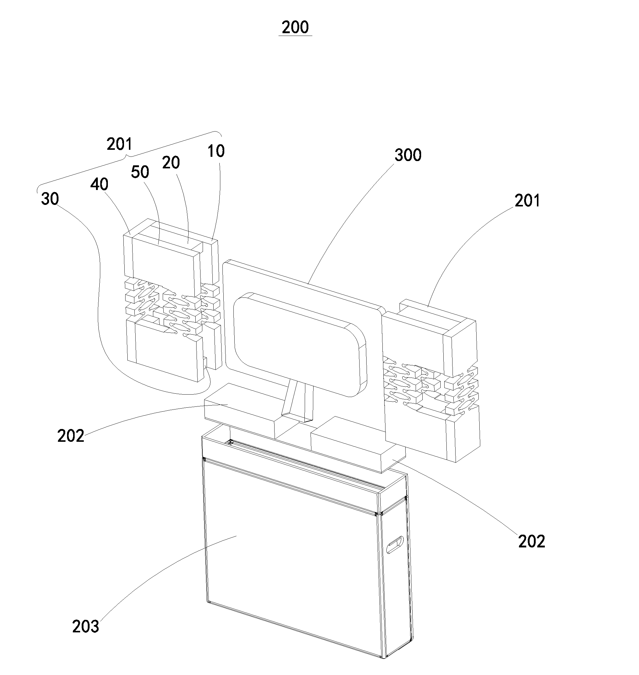
[0010] FIGS. 1 to 3 illustrate a packaging container 200 for packaging a device which can be used to display images (display device 300). It is understood that the packaging container 200 can also be used to package other products. The packaging container 200 includes a packaging box 203, two protecting covers 201, and two base wads 202.
[0011] The two protecting covers 201 are received in an inner space of the packaging box 203 and respectively disposed near two opposite ends of the packaging box 203 to package two opposite sides of the display device 300. The two base wads 202 can be placed on the bottom of the packaging box 203 to support a lower side of the display device 300.
[0012] In at least one exemplary embodiment, the protecting cover 201 can further include a first block member 20, a second block member 30, a third block member 60, and a fourth block member 70.
[0013] The first block member 20 can be connected between an upper end of the first packaging liner 10 and an upper end of the second packaging liner 50. The second block member 30 can be connected between a lower end of the first packaging liner 10 and a lower end of the second packaging liner 50. The third block member 60 can be connected to an inner and upper side of the connecting packaging liner 40. The fourth block member 70 can be connected to an inner and lower side of the connecting packaging liner 40. The first block member 20, a second block member 30, a third block member 60, and a fourth block member 70 can be used to fill empty spaces between the protecting covers 201 and the display device 300.
[0014] Each of the two protecting covers 201 can include a first packaging liner 10, a second packaging liner 50, and a connecting packaging liner 40.
[0015] The second packaging liner 50 is parallel to the first packaging liner 10 and spaced apart from the first packaging liner 10. The connecting packaging liner 40 is connected between the first packaging liner 10 and the second packaging liner 50.
[0016] The first packaging liner 10, the second packaging liner 50 and the connecting packaging liner 40 can be identical. The first packaging liner 10 will be taken as an example to be described, the second packaging liner 50 and the connecting packaging liner 40 are similar.
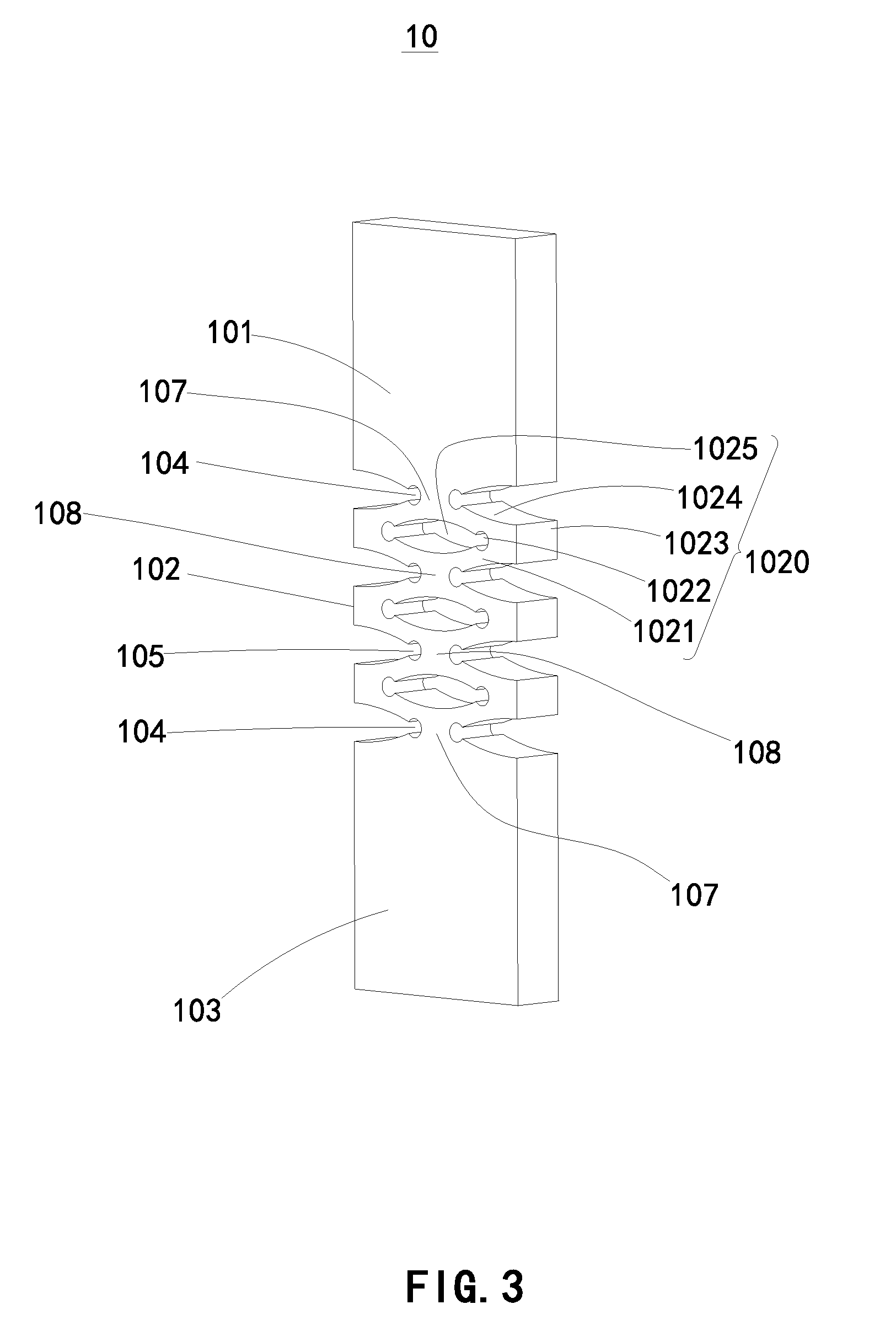
[0017] The first packaging liner 10 can include a first resisting section 101, a second resisting section 103, and a deforming section 102.
[0018] The second resisting section 103 is on one side of the deforming section 102 and the first resisting section 101 is on an opposite side of the deforming section 102. The deforming section 102 is connected between the first resisting section 101 and the second resisting section 103.
[0019] The deforming section can include a plurality of elastic members 1020. When at least one of the first resisting section 101 and the second resisting section 103 is compressed or stretched, the deforming section 102 deforms through deformation of the elastic members 1020, so that the first packaging liner 10 can be elastically deformed to adapt to hold display devices 300 with different size.
[0020] In at least one exemplary embodiment, each of elastic members 1020 can include a first extension arm 1021, a second extension arm 1024, and a connecting portion 1023. An end of the first extension arm 1021 and a corresponding end of the second extension arm 1024 are connected by the connecting portion 1023. An interspace 1025 is defined between the first extension arm 1021 and the second extension arm 1024.
[0021] The plurality of elastic members 1020 can be punch-formed. The interspace 1025 can be an oval punched hole.
[0022] The connecting portion 1023 can define a first arc-shaped gap 1022 thereon, the gap 1022 and the interspace 1025 are adjacent to and in air communication with each other. Two ends of the first arc-shaped gap 1022 extend to the first extension arm 1021 and the second extension arm 1024, so that the connection of the first extension arm 1021 and the second extension arm 1024 can be smooth, to avoid stress concentration on the connecting portion 1023.
[0023] Similarly, each connecting portion 107 of the deforming section 102 and the first resisting section 101 defines a second arc-shaped gap 104, and each connecting portion 107 of the deforming section 102 and the second resisting section 103 defines a second arc-shaped gap 104. Each of the connecting portions 108 of the plurality of elastic members 1020 defines a third arc-shaped gap 105.
[0024] The embodiments shown and described above are only examples. Even though numerous characteristics and advantages of the present technology have been set forth in the foregoing description, together with details of the structure and function of the present disclosure, the disclosure is illustrative only, and changes may be made in the details, including matters of shape, size, and arrangement of the parts within the principles of the present disclosure, up to and including the full extent established by the broad general meaning of the terms used in the claims.
* * * * *
D00000
D00001
D00002
D00003
XML
uspto.report is an independent third-party trademark research tool that is not affiliated, endorsed, or sponsored by the United States Patent and Trademark Office (USPTO) or any other governmental organization. The information provided by uspto.report is based on publicly available data at the time of writing and is intended for informational purposes only.
While we strive to provide accurate and up-to-date information, we do not guarantee the accuracy, completeness, reliability, or suitability of the information displayed on this site. The use of this site is at your own risk. Any reliance you place on such information is therefore strictly at your own risk.
All official trademark data, including owner information, should be verified by visiting the official USPTO website at www.uspto.gov. This site is not intended to replace professional legal advice and should not be used as a substitute for consulting with a legal professional who is knowledgeable about trademark law.