Disposable Filter With An Accessory Port
Remboski; Donald ; et al.
U.S. patent application number 16/135722 was filed with the patent office on 2019-03-21 for disposable filter with an accessory port. The applicant listed for this patent is Aware Mobility LLC, Neapco Intellectual Property Holdings, LLC. Invention is credited to Jacqueline Dedo, Donald Remboski.
| Application Number | 20190083908 16/135722 |
| Document ID | / |
| Family ID | 65719810 |
| Filed Date | 2019-03-21 |

| United States Patent Application | 20190083908 |
| Kind Code | A1 |
| Remboski; Donald ; et al. | March 21, 2019 |
DISPOSABLE FILTER WITH AN ACCESSORY PORT
Abstract
A disposable filter for filtering a working fluid including a housing having an inlet to be disposed in fluid communication with a working fluid and an outlet to be disposed in fluid communication with a machine. A filter media is disposed within the housing for filtering the working fluid passing through the disposable filter between the inlet and outlet. At least one accessory port is positioned adjacent to and fluidly connected to at least one of the inlet and the outlet for receiving an accessory for monitoring a characteristic of the working fluid passing through the inlet or the outlet of the disposable filter and/or an operational condition of the disposable filter or associated machinery.
| Inventors: | Remboski; Donald; (Ann Arbor, MI) ; Dedo; Jacqueline; (Wolverine Lake, MI) | ||||||||||
| Applicant: |
|
||||||||||
|---|---|---|---|---|---|---|---|---|---|---|---|
| Family ID: | 65719810 | ||||||||||
| Appl. No.: | 16/135722 | ||||||||||
| Filed: | September 19, 2018 |
Related U.S. Patent Documents
| Application Number | Filing Date | Patent Number | ||
|---|---|---|---|---|
| 62560979 | Sep 20, 2017 | |||
| 62560854 | Sep 20, 2017 | |||
| 62560919 | Sep 20, 2017 | |||
| Current U.S. Class: | 1/1 |
| Current CPC Class: | B01D 35/30 20130101; B01D 27/04 20130101; B01D 37/046 20130101; B01D 27/101 20130101; B01D 35/06 20130101; B01D 27/08 20130101; B01D 37/043 20130101; B01D 2201/56 20130101; B01D 2201/4092 20130101; B01D 2201/52 20130101; B03C 1/30 20130101; B01D 27/14 20130101; B01D 35/147 20130101; B01D 35/143 20130101; B01D 2201/54 20130101; B01D 35/005 20130101; B01D 27/103 20130101; B01D 27/108 20130101; B01D 35/1435 20130101; B01D 37/048 20130101; B03C 1/28 20130101 |
| International Class: | B01D 27/08 20060101 B01D027/08; B01D 27/10 20060101 B01D027/10; B01D 27/14 20060101 B01D027/14; B01D 35/00 20060101 B01D035/00; B01D 35/06 20060101 B01D035/06; B01D 35/147 20060101 B01D035/147; B03C 1/28 20060101 B03C001/28; B03C 1/30 20060101 B03C001/30 |
Claims
1. A disposable filter for filtering a working fluid comprising: a housing including an inlet to be disposed in fluid communication with a working fluid and an outlet to be disposed in fluid communication with a machine; a filter media disposed within said housing for filtering said working fluid passing through said disposable filter between said inlet and outlet; and at least one accessory port positioned adjacent to and fluidly connected at least one of said inlet and said outlet for receiving an accessory for monitoring a characteristic of said working fluid passing through said inlet or said outlet of the disposable filter and/or an operational condition of the disposable filter or associated machinery.
2. A disposable filter of claim 1 further including an accessory coupled with said accessory port for monitoring a characteristic of said working fluid passing through said inlet or said outlet of said disposable filter and/or an operational condition of the disposable filter or associated machinery.
3. A disposable filter of claim 2 wherein said accessory is a getter and includes a magnet for drawing particulate from said working fluid toward said magnet, and a sight window for allowing a user to inspect said particulate drawn to said magnet.
4. A disposable filter of claim 3 wherein said magnet is removably connected to said window to allow said magnet to be removed from said window such that said window may be cleaned.
5. A disposable filter of claim 2 wherein said accessory includes a sight window for allowing a user to observe working fluid flowing within said disposable filter.
6. A disposable filter of claim 2 wherein said accessory includes at least one sensor configured to measure at least one of pressure, temperature, flow rate, chemical composition moisture levels, an additive measure, optical transmissibility, reflection level, a light scattering level, a thermal capacity, a surface acoustic wave measurement, and an ultrasonic wavelength of said working fluid.
7. A disposable filter of claim 2 further including a controller for analyzing characteristics of said working fluid acquired by said accessory.
8. A disposable filter of claim 7 wherein said accessory includes a communication module in wireless electronic communication with said controller for wirelessly communicating said measured characteristics of said working fluid, the disposable filter or associated machinery to said controller.
9. A disposable filter of claim 7 wherein said controller is positioned remote from said accessory.
10. A disposable filter of claim 2 wherein said accessory is detachably coupled with said accessory port.
11. A disposable filter of claim 1 further including a bypass structure adjacent to said fluid outlet and configured to maintain a predetermined pressure within said disposable filter.
12. A disposable filter of claim 11 further including a bypass indicating device connected to said bypass structure and configured to indicate a status of said bypass structure.
13. A disposable filter of claim 12 wherein said bypass indicating device is positioned adjacent to said accessory port.
14. A disposable filter of claim 3 wherein a seal is positioned within said accessory port for sealing said connection between said accessory port and said accessory.
15. A disposable filter of claim 3 further including a valve connected to said accessory portion for selectively fluidly connecting and disconnecting said disposable filter from said accessory through said accessory port and to allow different accessories to be coupled with said accessory port while preventing said leakage of fluid from within said disposable filter.
16. A disposable filter of claim 15 wherein said valve is a flapper valve.
17. A filter system as set forth in claim 1 wherein said housing has a generally cylindrical shape and extends between a bottom surface and a top surface, and wherein said top surface of said housing defines said inlet, and wherein said top surface of said housing further defines said outlet at a position that is radially inward of said inlet.
18. A filter system as set forth in claim 17 wherein said filter media is positioned radially between said inlet and said outlet.
19. A filter system as set forth in claim 1 wherein said housing includes a connector for allowing said housing to be coupled with said machine.
20. A filter system as set forth in claim 19 wherein said connector is a threaded connection for allowing said housing to be threaded onto a corresponding threaded connection on said machine.
Description
CROSS REFERENCE TO RELATED APPLICATIONS
[0001] The subject application claims the benefit of U.S. Provisional Patent Application Ser. No. 62/560,979 filed on Sep. 20, 2017 entitled "Filter System Including Integrated Diagnostics", U.S. Provisional Patent Application Ser. No. 62/560,854 filed on Sep. 20, 2017 entitled a "Disposable Filter Including an Integrated Sensor Assembly", and U.S. Provisional Patent Application Ser. No. 62/560,919 filed on Sep. 20, 2017 entitled a "Disposable Filter Including an Accessory Port", the entire disclosures of these provisional patent applications are incorporated herein by reference.
FIELD OF THE DISCLOSURE
[0002] The present disclosure relates generally to a filter for filtering a working fluid passing therethrough. More specifically, the present disclosure relates to a disposable filter with an accessory port for receiving an accessory which is configured to provide information related to various characteristics of the filtered working fluid or an operational condition of the disposable filter or associated machinery.
BACKGROUND OF THE INVENTION
[0003] This section provides a general summary of background information and the comments and examples provided in this section are not necessarily prior art to the present disclosure.
[0004] It is known in the art for various types of machinery, e.g., automobiles, construction equipment, and manufacturing devices, to include filters for removing impurities from working fluids such as fuel, oil, gas and coolant. Cartridges of the filters are known to clog with impurities and thus must periodically be replaced. Additionally, it has been found that significant information about the working fluid and other parts of the machinery can be obtained based on characteristics of the working fluid as it passes through the filter. For example, when filtering bulk fuel delivered to a storage site, a filter system can identify contamination in the fuel and therefore identify supply chain problems. As another example, when filtering working fluid to an engine or hydraulic system, the filter system can identify abnormal chemical or physical properties of the lubricant or hydraulic fluid. Accordingly, it is known to manually conduct working fluid sampling and analysis to detect problems associated with the working fluid and other parts of the machinery for ensuring product or process fluid quality. In some cases, the filter cartridges and working fluid are manually inspected based on predetermined, static inspection schedules. It is also known for condition-based monitoring systems to be built into machines to actively monitor their working fluids. However, such condition-based monitoring systems are not readily serviceable and replaceable, and can add significant expense to the machine. Accordingly, there remains a need for improvements to such monitoring systems to reduce maintenance costs and improve machine performance, machine useful lifetime and fluid quality.
SUMMARY OF THE INVENTION
[0005] The subject invention is generally directed to a disposable filter which includes an accessory port for being coupled with an accessory which is configured to monitor a characteristic of the working fluid passing through the filter and/or an operational condition of the disposable filter or associated machinery. The accessory port provides a simple and inexpensive means for connecting and disconnecting accessories to the disposable filter. Accordingly, maintenance costs may be minimized because accessories may be easily be disconnected from an old filter and reused on a new filter, thus allowing the accessories to be reused many times. Furthermore, the invention provides an easy to integrate means of implementing accessories in circumstances where integration is often difficult, such as typical engine applications where there is no space for adding plumbing and sensors. Additionally, the invention offers condition-based maintenance without the cost of an expensive retrofit.
BRIEF DESCRIPTION OF THE DRAWINGS
[0006] The drawings described herein are for illustrative purposes only of selected embodiments and not all possible implementations, and are not intended to limit the scope of the present disclosure.
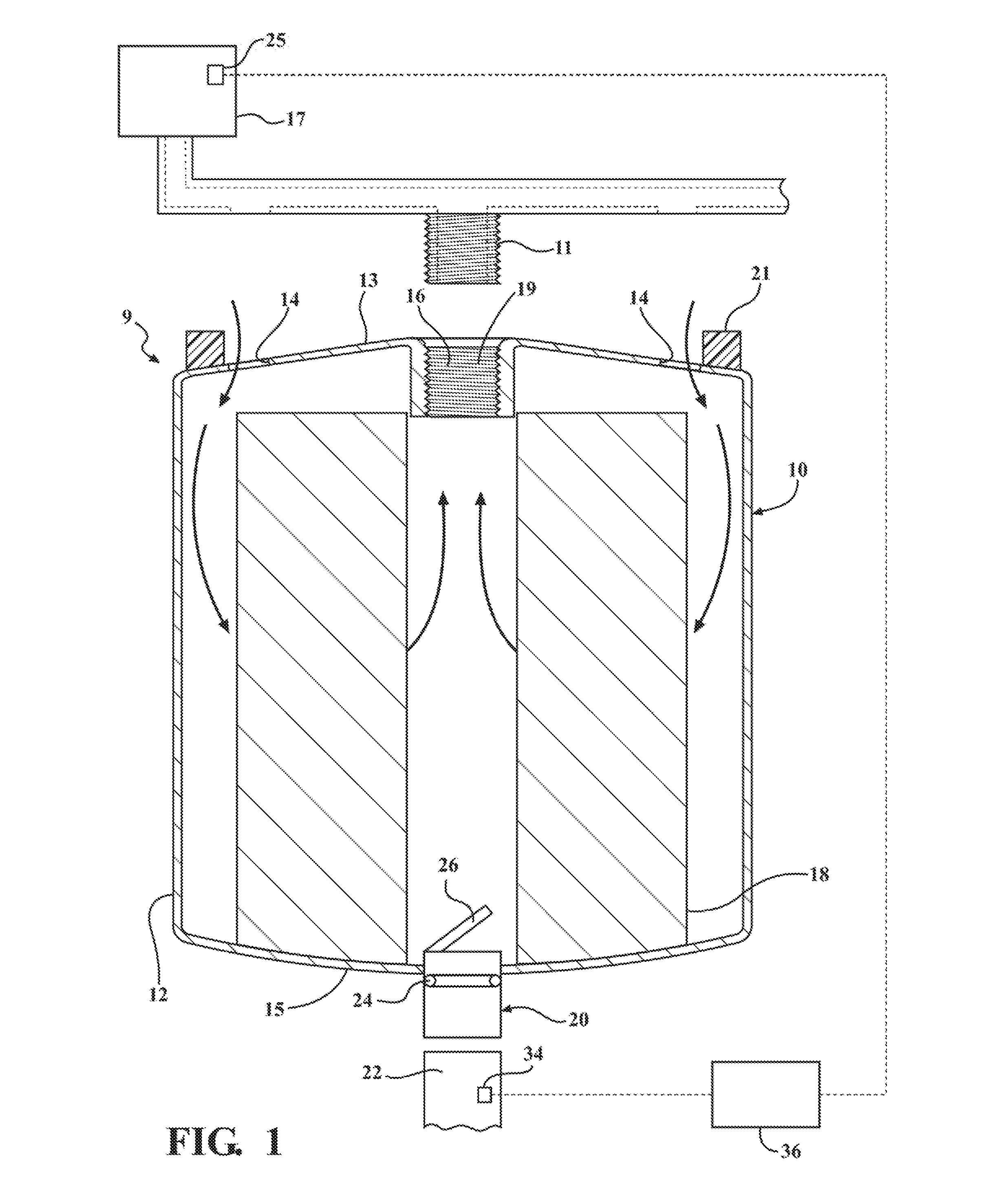
[0007] FIG. 1 illustrates a cross-sectional view of a disposable filter including a first enabling embodiment of an accessory port;
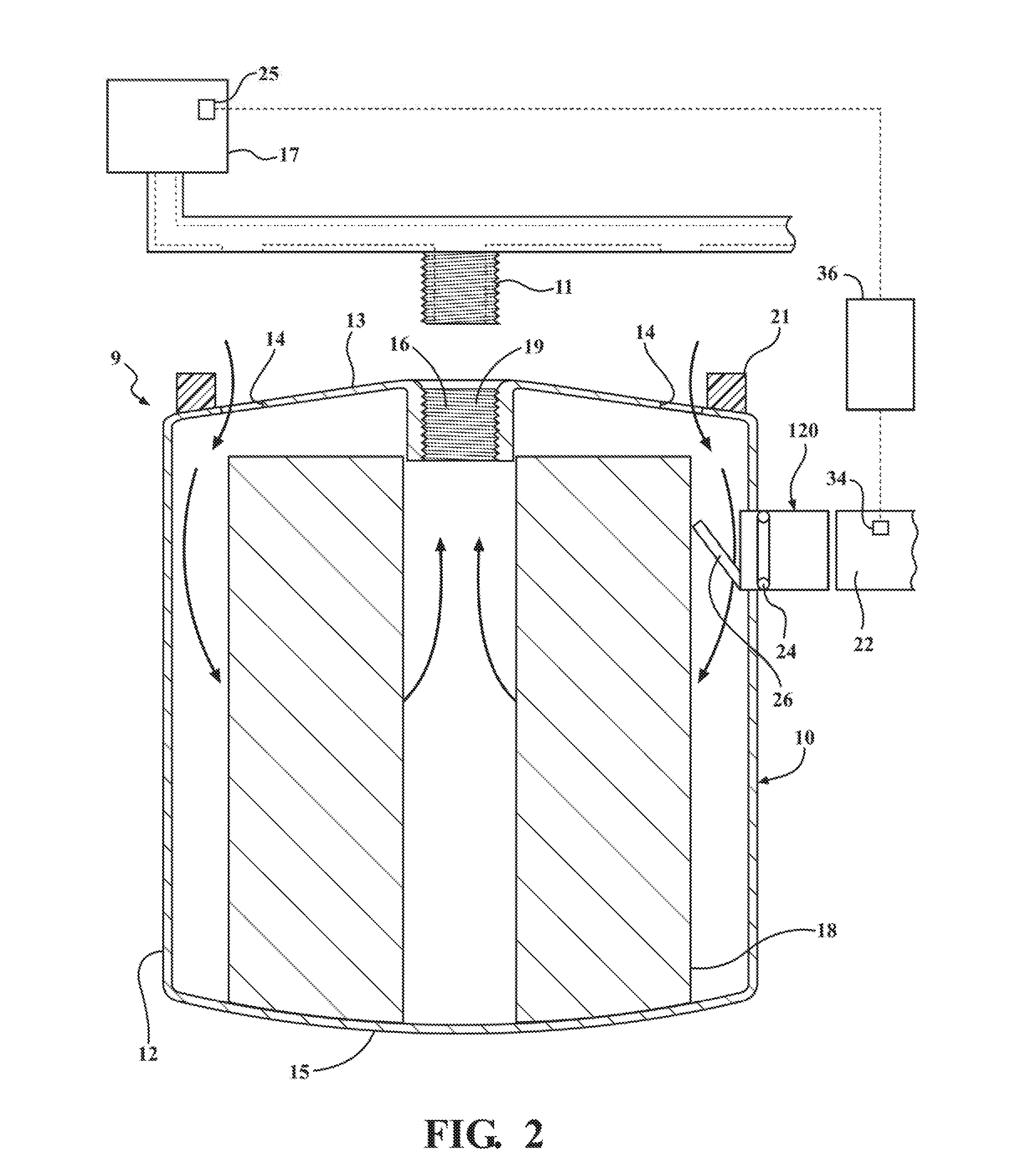
[0008] FIG. 2 illustrates a cross-sectional view of a disposable filter including a second enabling embodiment of an accessory port;
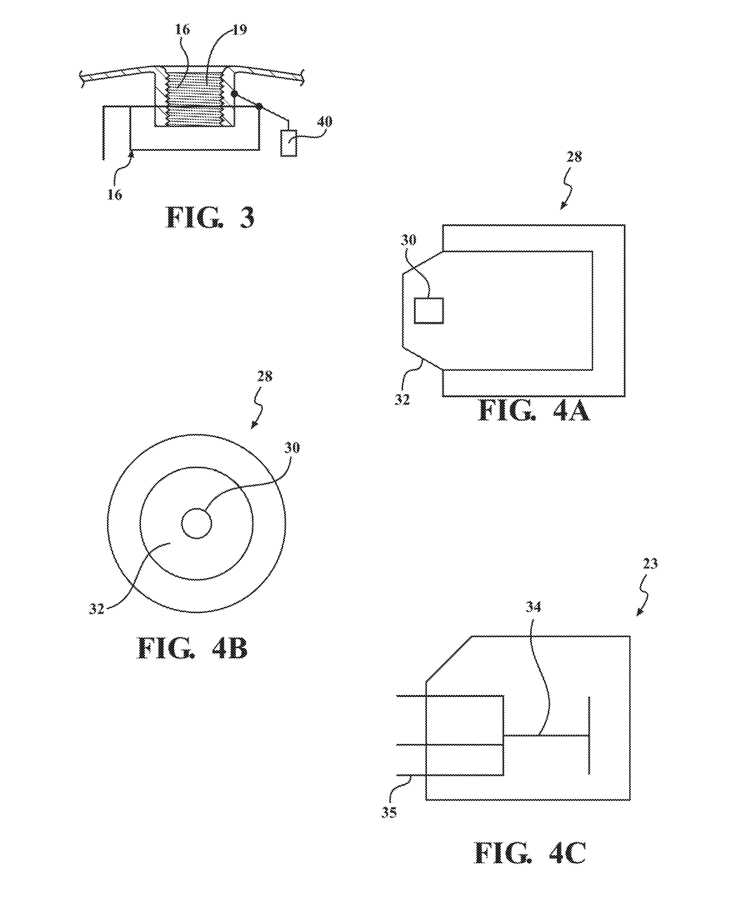
[0009] FIG. 3 illustrates a schematic view of a bypass structure incorporated into the first enabling embodiment of the disposable filter;
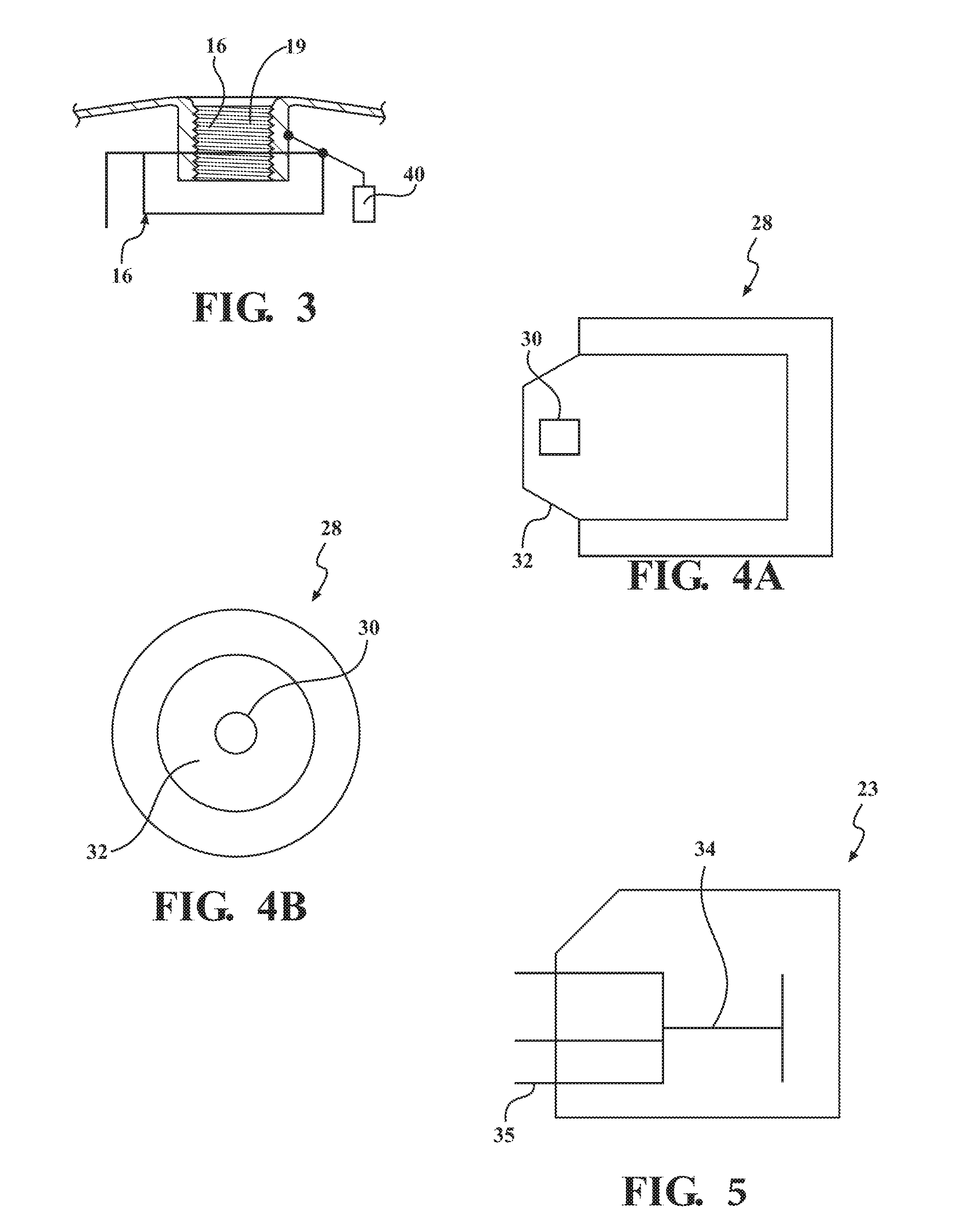
[0010] FIG. 4A illustrates a side cross-sectional view of a magnetic getter;
[0011] FIG. 4B illustrates a front view of the magnetic getter of FIG. 4A; and
[0012] FIG. 5 illustrates a schematic view of an example accessory including a plurality of sensors and a communications module.
DETAILED DESCRIPTION OF THE ENABLING EMBODIMENTS
[0013] Example embodiments of a filter system which includes an accessory in accordance with the present disclosure will now be more fully described. Each of these example embodiments are provided so that this disclosure is thorough and fully conveys the scope of the inventive concepts, features and advantages to those skilled in the art. To this end, numerous specific details are set forth such as examples of specific components, devices and mechanisms associated with the filter system to provide a thorough understanding of each of the embodiments associated with the present disclosure. However, as will be apparent to those skilled in the art, not all specific details described herein need to be employed, the example embodiments may be embodied in many different forms, and thus should not be construed or interpreted to limit the scope of the disclosure.
[0014] FIGS. 1-2 illustrate a filter system 9 in accordance with an aspect of the subject disclosure. As best shown therein, the filter system includes a disposable filter 10 which includes a housing 12 having a generally cylindrical shape and extending between a top surface 13 and a bottom surface 15. The top surface 13 defines an inlet 14 to be disposed in fluid communication with a source of working fluid as well as an outlet 16 to be disposed in fluid communication with a machine 17 for receiving the working fluid after passing through the disposable filter 10. The housing 12 may be of various materials such as metal or plastic. A filter media 18 is disposed within the housing 12 in a path of fluid communication between the inlet and outlet 14, 16 for filtering the working fluid prior to its delivery to the intended machine 17. A threaded, female connector 19 is disposed adjacent a top portion of the filter housing 12 for allowing the disposable filter 10 to be threaded onto a corresponding male connector 11 of the filter system 9 to allow for easy attachment of the disposable filter 10 (i.e., a disposable "spin-on" type filter). A gasket 21 is provided which encircles or is disposed around a top portion of the disposable filter 10 for sealing the filter 10 when it is connected to corresponding machinery 17.
[0015] As best illustrated in FIGS. 1 and 2, the disposable filter 10 includes an accessory port 20, 120 for being coupled with an accessory 22 that is configured to monitor a characteristic of the working fluid passing through the inlet 14 or the outlet 16 of the filter 10 and/or an operational condition of the disposable filter 10 or corresponding machinery 17. According to a first enabling embodiment of the accessory port 20 illustrated in FIG. 1, the accessory port 20 is positioned adjacent to and fluidly connected to the outlet 16 of the filter 10 for monitoring the working fluid that has already passed through the filter media 18. According to a second example embodiment of the accessory port 120 illustrated in FIG. 2, the accessory port 120 is positioned adjacent to and fluidly connected to the inlet 14 of the filter 10 for monitoring the working fluid as it enters the filter 20 prior to passing through the filter media 18. It should be appreciated that alternatively, an accessory port 20, 120 may be provided at both the inlet 14 and outlet 16 of the filter 10 for monitoring the working fluid prior to, and after passing through the filter media 18.
[0016] The accessory 22 may be coupled with the accessory port 20, 120 by using various means including, but not limited to, a threaded connection or interference fit. A ring seal 24 is provided within the accessory port 20, 120 for sealing the connection between the accessory port 20, 120 and the accessory 22. It should be appreciated that various other types of seals could be utilized. A valve 26 is provided adjacent to the accessory port 20, 120 for selectively fluidly connecting and disconnecting the filter 10 from the accessory 22 through the accessory port 20, 120. It should be appreciated that various types of valves may be utilized, e.g., a flapper valve, and the valve 26 may be mechanically or electrically actuated. The valve 26 may be utilized to allow accessories 22 to be swapped at the accessory port 20, 120 while preventing the leakage of working fluid from within the filter 10. It should also be appreciated that the accessory 22 may alternatively be integrated into an interposer structure that sits between the filter 10 and the machinery 17 to which the filter 10 is attached.
[0017] Various types of accessories 22 may be coupled with the accessory port 20, 120 including, but not limited to, passive electronics, active electronics and mechanical indicators. For example, an accessory 22 may include a getter 28--either magnetic or chemical, such as that shown in FIGS. 4A-4B. Such a getter 28 may include a magnet 30 and a sight window 32 for allowing a user to inspect particulate drawn to the magnet 30. The magnet 30 and window 32 are configured such that the magnet 30 is removable from the window 32 to allow for easy cleaning of the window 32. The accessory 22 may also include a stand-alone sight window for allowing a user to observe working fluid flowing to and away from the filter 10. The accessory 22 may also include one or more sensors for making various chemical or physical measurements of the working fluid such as pressure, temperature, flow rate, chemical composition, moisture levels, an additive measurement, optical transmissibility, reflection level, a light scattering level, a thermal capacity, a surface acoustic wave measurement, ultrasonic wavelength, various electrical properties and various magnetic properties. The accessory 22 may further include one or more sensors for monitoring filter properties and properties of the associated machinery 17 such as bypass valve actuation, a change in pressure and filter media electrical, vibrations and magnetic characteristics. The accessory 22 may also include other devices such as a chemical doser, for example, to meter out oil additives, or a mechanical indicator such as a toggle, flag or gauge.
[0018] In a preferred arrangement, the accessory 22 includes a communication module 34, such as an antenna, RFID tag, or the like, for wirelessly communicating the measured/monitored characteristic of the working fluid, the disposable filter 10 or associated machinery 17 to a controller 36 disposed remotely from the filter 10. The communication module 34 may be wireless, and thus may be powered by a battery or a flow activated generator. The communication module 34 may alternatively be wired to the controller 36. An exemplary accessory 23 is presented in FIG. 5 which includes a plurality of fluid sensing elements 35 which are connected to a single communications module 34. This arrangement allows a single accessory 23 to measure multiple parameters of the working fluid, filter or associated machinery 17.
[0019] Once transmitted to the controller 36, the acquired characteristics of the working fluid or the performance characteristic(s) of the disposable filter 10 or associated machinery 17 can be analyzed by the controller 24 to autonomously determine a condition of the disposable filter 10, working fluid passing therethrough or associated machinery 17. This data can then be utilized to determine if the disposable filter 10 and the machinery 17 in communication with the filtered working fluid are in proper operating condition or alternatively need service or replacement. For example, based on complete or nearly complete operating history of the disposable filter 10 and the working fluid passing therethrough, an optimal maintenance schedule and a prediction of the machine's 17 remaining useful life can be determined.
[0020] The controller 36 may take various forms and retrieved data from the accessory 22 may be transmitted to the controller 36 by way of various means. For example, the controller 36 may be a computer that is positioned in a vehicle or it may take the form of a smartphone. In these cases, the controller 24 may connect to the accessory 22 by way of connections such as a Bluetooth.RTM., TPM, Zigbee.RTM. or Near-field connection. Additionally, it should be appreciated that the accessory 22 may be disconnected from the accessory port 20, 120 and moved to a new location for examination by a remotely located controller 36 or other inspection tool. The controller 36 may be disposed in communication with various component systems 25 of the machine 17 such as pumps, hoses transmission, etc. to couple data from these other sources on the machine 17 with the filter characteristics to further aid and optimize a prediction of the machine state.
[0021] As best illustrated in FIG. 3, according to one aspect, the disposable filter 10 can include a pressure bypass structure 38, such as a bypass valve, or the like, disposed adjacent the fluid outlet 16 for maintaining a predetermined pressure within the disposable filter 10. A bypass flag 40 or other bypass indicating device may be positioned adjacent to the accessory port 20, 120 for indicating a status of the bypass structure 38. Since the accessory port 20, 120 is located remote from the bypass structure 38, the bypass flag 40 allows the state of the bypass structure 38 to be communicated remotely from the accessory port 20, 120.
[0022] Accordingly, as will be appreciated by the subject disclosure, the integration of the accessory port 20, 120 provides a low-cost approach to implementing condition-based maintenance of the disposable filter 10 and working fluid quality control into an existing filter system without the need for an expensive retrofit. Additionally, the accessory port 20, 120 advantageously allows limitless types of accessories 22 to be coupled with the filter 10 based on current needs. Additionally, the subject system provides for an easy method of integrating a means of integrating accessories 22 in circumstances where integration is often difficult, such as typical engine applications where there is no space for added plumbing and sensors.
[0023] The foregoing description of the embodiments has been provided for purposes of illustration and description. It is not intended to be exhaustive or to limit the disclosure. Individual elements or features of a particular embodiment are generally not limited to that particular embodiment, but, where applicable, are interchangeable and can be used in a selected embodiment, even if not specifically shown or described. The same may also be varied in many ways. Such variations are not to be regarded as a departure from the disclosure, and all such modifications are intended to be included within the scope of the disclosure.
* * * * *
D00000
D00001
D00002
D00003
D00004
XML
uspto.report is an independent third-party trademark research tool that is not affiliated, endorsed, or sponsored by the United States Patent and Trademark Office (USPTO) or any other governmental organization. The information provided by uspto.report is based on publicly available data at the time of writing and is intended for informational purposes only.
While we strive to provide accurate and up-to-date information, we do not guarantee the accuracy, completeness, reliability, or suitability of the information displayed on this site. The use of this site is at your own risk. Any reliance you place on such information is therefore strictly at your own risk.
All official trademark data, including owner information, should be verified by visiting the official USPTO website at www.uspto.gov. This site is not intended to replace professional legal advice and should not be used as a substitute for consulting with a legal professional who is knowledgeable about trademark law.