Wearable Injector With Sterile Adhesive Patch
Nekouzadeh; Ali ; et al.
U.S. patent application number 16/049850 was filed with the patent office on 2019-03-21 for wearable injector with sterile adhesive patch. The applicant listed for this patent is AMGEN INC.. Invention is credited to Yasaman Damestani, Bryton De Guia, Justin Harris, Matthew Wayne Janke, Joshua Merilos, Chitra Nadig, Ali Nekouzadeh, Edward Stapleford Nielsen, Jerome Olivas, Marc Orloff, Guojie Song.
| Application Number | 20190083702 16/049850 |
| Document ID | / |
| Family ID | 63207892 |
| Filed Date | 2019-03-21 |


| United States Patent Application | 20190083702 |
| Kind Code | A1 |
| Nekouzadeh; Ali ; et al. | March 21, 2019 |
WEARABLE INJECTOR WITH STERILE ADHESIVE PATCH
Abstract
An adhesive patch for a drug delivery device with a bacteria impermeable sterility margin surrounding an edge surface of the adhesive patch is disclosed, as well as a drug delivery device fixed to such an adhesive patch and a method of assembling a drug delivery device with such an adhesive patch. In some arrangements, the sterility margin is attached to or integral with a lower liner on a lower surface of the adhesive patch. In other arrangements, the sterility margin is attached to or integral with an upper liner on an upper surface of the adhesive patch.
| Inventors: | Nekouzadeh; Ali; (Simi Valley, CA) ; Olivas; Jerome; (Thousand Oaks, CA) ; Merilos; Joshua; (Thousand Oaks, CA) ; Janke; Matthew Wayne; (Simi Valley, CA) ; Harris; Justin; (Reseda, CA) ; Orloff; Marc; (Calabasas, CA) ; Nielsen; Edward Stapleford; (Ventura, CA) ; Nadig; Chitra; (Chatsworth, CA) ; Damestani; Yasaman; (Thousand Oaks, CA) ; Song; Guojie; (Moorpark, CA) ; De Guia; Bryton; (Newbury Park, CA) | ||||||||||
| Applicant: |
|
||||||||||
|---|---|---|---|---|---|---|---|---|---|---|---|
| Family ID: | 63207892 | ||||||||||
| Appl. No.: | 16/049850 | ||||||||||
| Filed: | July 31, 2018 |
Related U.S. Patent Documents
| Application Number | Filing Date | Patent Number | ||
|---|---|---|---|---|
| 62547500 | Aug 18, 2017 | |||
| Current U.S. Class: | 1/1 |
| Current CPC Class: | A61M 2005/14252 20130101; A61M 5/20 20130101; A61M 5/14248 20130101; A61M 2205/587 20130101; A61M 2205/58 20130101; A61M 2205/0205 20130101; A61M 2205/50 20130101; A61M 2005/14264 20130101; A61M 2205/0238 20130101 |
| International Class: | A61M 5/142 20060101 A61M005/142; A61M 5/20 20060101 A61M005/20 |
Claims
1. A drug delivery device comprising: a housing having a bottom wall; an adhesive patch adhered to the bottom wall and having an area contained within an outer perimeter, the area having an upper surface, a lower surface, and an edge surface at the outer perimeter between the upper surface and the lower surface; a bacteria impermeable lower liner on the lower surface; and a bacteria impermeable sterility margin surrounding the edge surface.
2. The drug delivery device of claim 1, wherein the bacteria impermeable sterility membrane is attached to or integral with the adhesive patch or the lower liner.
3. (canceled)
4. The drug delivery device of claim 1, further comprising a bacteria impermeable upper liner on the upper surface, wherein the sterility margin is optionally attached to or integral with the upper liner.
5-8. (canceled)
9. The drug delivery device of claim 1, wherein the outer perimeter of the adhesive patch is pre-cut in a perforated manner to separate from the sterility margin.
10. (canceled)
11. The drug delivery device of claim 1, wherein the housing includes an interior space and a top wall, a container is disposed within the interior space, and the top wall includes a window positioned to allow viewing of the container, the window including a polarized filter that filters out up to and including 50% of light in the visible range.
12. An adhesive system for use with a wearable drug delivery device, the system comprising: an adhesive patch having an outer perimeter, an upper surface, a lower surface, and an edge surface at the outer perimeter and extending between the upper surface and the lower surface; a bacteria impermeable lower liner on the lower surface; and a bacteria impermeable sterility margin surrounding the edge surface.
13. The adhesive system of claim 12, wherein the bacteria impermeable sterility membrane is attached to or integral with the adhesive patch or the lower liner.
14. (canceled)
15. The adhesive system of claim 12, further comprising a bacteria impermeable upper liner on the upper surface, wherein the sterility margin is optionally attached to or integral with the upper liner.
16. (canceled)
17. The adhesive system of claim 12, wherein the upper liner includes a pre-cut first perimeter surrounding a portion of an area of the adhesive patch that is configured to be adhered to a drug delivery device.
18. The adhesive system of claim 12, further comprising a hole provided in the area to allow passage of a delivery member of the drug delivery device.
19. The adhesive system of claim 12, wherein the outer perimeter is pre-cut in a perforated manner to separate from the sterility margin.
20. The adhesive system of claim 12, wherein the sterility margin has a width of at least two millimeters.
21. A method of preparing a drug delivery device for use, the method comprising: providing an adhesive patch, the adhesive patch including an area contained within an outer perimeter, the area having an upper surface, a lower surface, and an edge surface at the outer perimeter between the upper surface and the lower surface, a bacteria impermeable lower liner on the lower surface, and a bacteria impermeable sterility margin surrounding the edge surface; providing a sub-assembly of a drug delivery device comprising an insertion mechanism; adhering the upper surface of the adhesive patch to the drug delivery device.
22. The method of claim 21, further comprising aligning a hole in the adhesive patch with the insertion mechanism of the sub-assembly of the drug delivery device prior to adhering the adhesive patch to the drug delivery device.
23. The method of claim 21, further comprising sterilizing the adhesive patch and the sub-assembly of the drug delivery device after adhering the adhesive patch to the drug delivery device.
24. The method of any of claim 21, further comprising (a) filling a container of the drug delivery device in a sterile fill line and optionally (b) connecting the sub-assembly of the drug delivery device to additional parts of the drug delivery device in an environment that is sterile or non-sterile.
25. (canceled)
26. The method of claim 21, further comprising removing a portion of an upper liner from the top surface of the adhesive patch prior to adhering the upper surface of the adhesive patch to the drug delivery device.
27. The method of claim 21, further comprising removing the bacteria impermeable sterility margin prior to use.
28. The method of claim 27, wherein removing the bacteria impermeable sterility margin comprises at least one of (a) through (d): (a) removing the sterility margin simultaneously with removing a lower liner from the lower surface of the adhesive patch, (b) removing the sterility margin simultaneously with removing an upper liner from the upper surface of the adhesive patch, (c), removing the sterility margin after and separately of removing a lower liner from the lower surface of the adhesive patch or (d) removing the sterility margin after and separately of removing an upper liner from the upper surface of the adhesive patch.
29-31. (canceled)
32. The method of claim 21, further comprising sealing the insertion mechanism to a bottom wall of the drug delivery device so that the contact between the bottom wall and the insertion mechanism is bacteria impermeable.
Description
CROSS-REFERENCE TO RELATED APPLICATIONS
[0001] The priority benefit of U.S. Provisional Patent Application No. 62/547,500, filed Aug. 18, 2017, is claimed and the entire contents thereof are incorporated by reference herein.
FIELD OF DISCLOSURE
[0002] The present disclosure generally relates to wearable drug delivery devices and, more particularly, to a sterile adhesive patch for a wearable drug delivery device.
BACKGROUND
[0003] Some drug delivery devices, such as on-body injectors, may be temporarily attached to a patient to deliver a drug via an injection needle or some other means over an extended period of time. The drug delivery device may be attached to the tissue of the patient's abdomen, thigh, arm, or some other portion of the patient's body. In some cases, the drug delivery device may be worn by the patient for several minutes or hours while the drug is injected. For example, viscous drugs, including some biologics, can have long injection times due to the force needed to expel them from the drug delivery device. Furthermore, some drug delivery devices are configured to be attached to the patient at a doctor's office, and then later deliver the drug to the patient when the patient returns to his or her home. During manufacturing and transport the bacteria or other harmful micro-organisms may adhere to the exposed surfaces of the adhesive and transfer to the patient once the drug delivery device is attached to the patient. This is true even of relatively small adhesive surfaces, such as the exposed edge surface at the perimeter of an adhesive patch created by the thickness of the patch.
[0004] Some drug delivery devices further include a window for viewing and inspection of the drug in order to determine, for example, whether delivery of the drug is complete. However, some drugs are photo sensitive and can be damaged by exposure to visible light. In order to protect such drugs, the size of viewing windows in drug delivery devices have been minimized or tinted. However, these solutions can make it more difficult to view the drug.
SUMMARY
[0005] In accordance with a first aspect, a drug delivery device includes a housing having a bottom wall. The drug delivery device also includes an adhesive patch adhered to the bottom wall and having an area contained within an outer perimeter, the area having an upper surface, a lower surface, and an edge surface at the outer perimeter between the upper surface and the lower surface. Additionally, the drug delivery device includes a bacteria impermeable lower liner on the lower surface and a bacteria impermeable sterility margin surrounding the edge surface.
[0006] In accordance with a second aspect, an adhesive patch for a drug delivery device includes an area contained within an outer perimeter, the area having an upper surface, a lower surface, and an edge surface at the outer perimeter between the upper surface and the lower surface. The adhesive patch also includes a bacteria impermeable lower liner on the lower surface and a bacteria impermeable sterility margin surrounding the edge surface.
[0007] In accordance with a third aspect, a method of assembling a drug delivery device comprises providing an adhesive patch, the adhesive patch including an area contained within an outer perimeter, the area having an upper surface, a lower surface, and an edge surface at the outer perimeter between the upper surface and the lower surface, a bacteria impermeable lower liner on the lower surface, and a bacteria impermeable sterility margin surrounding the edge surface. The method further includes providing a sub-assembly of a drug delivery device comprising an insertion mechanism. Additionally, the method includes adhering the adhesive patch to the drug delivery device.
[0008] In some arrangements, the bacteria impermeable sterility margin may be attached to or integral with the lower liner. In other arrangements, the adhesive patch further includes a bacteria impermeable upper liner on the upper surface, and the sterility margin may be attached to or integral with the upper liner. In some arrangements, the outer perimeter of the adhesive patch may be pre-cut in a perforated manner to separate from the sterility margin. In some arrangements, the sterility margin may have a width of at least two millimeters. In some arrangements, the upper liner may include a pre-cut first perimeter surrounding a portion of the area configured to be adhered to a drug delivery device. In some arrangements, a hole is provided in the area to allow passage of a delivery member of the drug delivery device.
[0009] In some arrangements, the housing includes an interior space and an insertion mechanism may be disposed within the interior space of the housing. The insertion mechanism may be activated to move a delivery member from a retracted position within the housing to a deployed position extending outside of the housing. A hole may be provided in the area of the adhesive patch to allow the delivery member to extend outside of the housing without having to penetrate the adhesive patch.
[0010] In some arrangements, the housing may include an interior space and a top wall. A container may be disposed within the interior space, and the top wall may include a window positioned to allow viewing of the container. The window may include a polarized filter that filters out up to and including 50% of light in the visible range.
[0011] In some variations of the method, a hole may be provided in the area of the adhesive patch, and the method may include aligning the hole of the adhesive patch with the insertion mechanism of the sub-assembly of the drug delivery device. In some variations, the method may include sterilizing the adhesive patch and the sub-assembly of the drug delivery device. In some variations, the sub-assembly of the drug delivery device may further include a container, and the method may include filling the container in a sterile fill line while the container is attached to a subassembly of the drug delivery device. In some variations, the method further includes connecting the sub-assembly of the drug delivery device to all remaining parts of the drug delivery device in an environment that may or may not be sterile. In some variations, the method further includes sealing the adhesive patch to the sub-assembly of the drug delivery device to prevent bacteria from entering the sterile regions of the adhesive patch, insertion mechanism and drug delivery device. In some variations, the method further includes sealing the insertion mechanism to the bottom wall to prevent bacteria from entering sterile regions of the adhesive patch, insertion mechanism and drug delivery device.
BRIEF DESCRIPTION OF THE DRAWINGS
[0012] It is believed that the disclosure will be more fully understood from the following description taken in conjunction with the accompanying drawings. Some of the drawings may have been simplified by the omission of selected elements for the purpose of more clearly showing other elements. Such omissions of elements in some drawings are not necessarily indicative of the presence or absence of particular elements in any of the exemplary embodiments, except as may be explicitly delineated in the corresponding written description. Also, none of the drawings are necessarily to scale.
[0013] FIG. 1 illustrates a schematic cross-sectional view of an embodiment of a drug delivery device in accordance with principles of the present disclosure.
[0014] FIG. 2 illustrates a drug delivery device having a viewing window, the drug delivery device adhered to an adhesive patch, in accordance with principles of the present disclosure.
[0015] FIG. 3A illustrates an adhesive patch prior to assembly with a drug delivery device in accordance with principles of the present disclosure.
[0016] FIG. 3B illustrates the adhesive patch of FIG. 3A as a portion of an upper liner within a pre-cut first perimeter is removed.
[0017] FIG. 3C illustrates the adhesive patch of FIGS. 3A and 3B as having a hole aligned with an insertion mechanism of the drug-delivery device.
[0018] FIG. 3D illustrates an exploded view of the assembled adhesive patch and drug delivery device sub-assembly of FIGS. 3A-3C.
[0019] FIG. 4 illustrates removal of a lower liner integral with or attached to the sterility margin in accordance with principles of the present disclosure.
[0020] FIG. 5A illustrates removal of a lower liner from an assembled adhesive patch and drug delivery device in accordance with principles of the present disclosure.
[0021] FIG. 5B illustrates removal of an upper liner integral with or attached to the sterility margin of the adhesive patch of FIG. 5A in accordance with principles of the present disclosure.
DETAILED DESCRIPTION
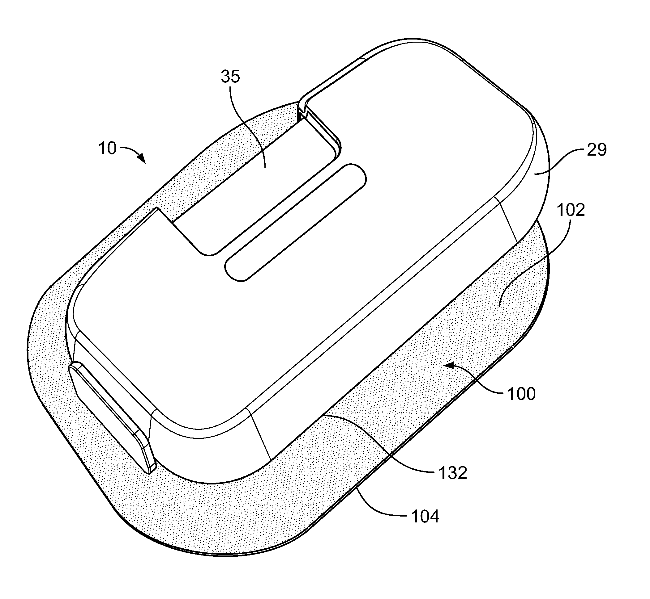
[0022] FIG. 1 is a schematic illustration of one embodiment of a drug delivery device 10 fixed to an adhesive patch 100. The drug delivery device 10 has a housing 29 with a bottom wall 25 to which the adhesive patch 100 is adhered. The adhesive patch 100 has an area 102 contained within an outer perimeter 104. The area 102 has an upper surface 110, a lower surface 112, and an edge surface 114 at the outer perimeter 104 between the upper surface 110 and the lower surface 112. A bacteria impermeable lower liner 120 is on the lower surface 112. In order to address the issue of bacteria collecting along the edge surface 114, the adhesive patch 100 advantageously includes a removable bacteria impermeable sterility margin 124. Further details regarding the adhesive patch 100 and the bacteria impermeable sterility margin 124 are discussed below with respect to FIGS. 2-5B.
[0023] Returning to FIG. 1, additional detail regarding on exemplary version of the specific drug delivery device 10 incorporated with the adhesive patch 100 of the present disclosure will be described. Other drug delivery devices are possible. The drug delivery device 10 may be operated to subcutaneously or transdermally deliver a drug to a patient. In the illustrated embodiment, the drug delivery device 10 is configured as a wearable drug delivery device, such as an on-body injector or an ambulatory infusion pump, and is releasably attachable to the patient's tissue 11 (e.g., the patient's skin). In other embodiments (not illustrated), the drug delivery device 10 may be configured as a pen-type injector, such as an autoinjector or injection pen, which is temporarily held against the patient's tissue 11 over the course of the injection. The drug delivery device 10 may be configured to automatically deliver a fixed or a patient/operator-settable dose of the drug over a controlled or selected period of time. Furthermore, the drug delivery device 10 may be intended for self-administration by the patient, or may be operated by a formally trained healthcare professional or other caregiver to administer the injection.
[0024] Generally, the drug delivery device 10 may include an insertion mechanism 12, a container 14, a fluid pathway assembly 22, a drive mechanism 24, and a controller 26, each of which may be disposed within an interior space of a main housing 29. An actuator 28 (e.g., a user-depressible button, touchscreen, microphone, etc.) may protrude through or otherwise be disposed at an exterior surface of the housing 29 and may be configured to initiate operation of the drug delivery device 10 by activating, via mechanical and/or electrical means (shown in dotted lines in FIG. 1), the insertion mechanism 12, the fluid pathway assembly 22, the drive mechanism 24, the controller 26, and/or other mechanisms and/or electronics. In embodiments where the actuator 28 is a button that is depressed or otherwise physically moved by a user or patient, the actuator 28 may be configured to exert a motive force needed to activate the insertion mechanism 12, the fluid pathway assembly 22, the drive assembly 24, the controller 26, and/or other mechanisms. In such embodiments, the actuator 28 may be physically connected to, either directly or indirectly via a mechanical linkage, the insertion mechanism 12, the drive mechanism 24, the fluid pathway assembly 22, and/or other mechanisms such that manually depressing or otherwise interacting with the actuator 28 supplies the motive force necessary to activate the insertion mechanism 12, the drive mechanism 24, the fluid pathway assembly 22, and/or other mechanisms. For example, in some embodiments, manually depressing the actuator 28 may cause the fluid pathway assembly 22 to move towards the stationary container 14, or cause the container 14 to move towards the stationary fluid pathway assembly 22, and thereby cause a container access needle to penetrate through a seal member into a reservoir or interior volume of the container 14. Additionally or alternatively, the actuator 28 may operate as an input device that transmits an electrical and/or mechanical signal to the controller 26, which in turn may execute programmable instructions to control operation of the insertion mechanism 12, the drive mechanism 24, the fluid pathway assembly 22, and/or other mechanisms. In such embodiments, the controller 26 may include a processor (e.g., a microprocessor) and a non-transitory memory for storing the programmable instructions to be executed by the processor. Furthermore, in such embodiments, the drug delivery device 10 may include an internal actuator (e.g., an electric motor, a pneumatic or hydraulic pump, and/or a source of pressurized gas or liquid) which is separate from the actuator 28 and which, in response to an electrical control signal received from the controller 26, exerts the motive force needed to activate the insertion mechanism 12, the drive mechanism 24, the fluid pathway assembly 22, and/or other mechanisms.
[0025] Still referring to FIG. 1, the housing 29 may include a bottom wall 25 configured to be releasably attached (e.g., adhered with an adhesive) to the patient's tissue 11, and a top wall 27 including one or more visual indicators 42 (e.g., lights, graphical displays, etc.) and/or a window 35 for viewing the container 14 and a drug 32 contained therein. The one or more visual indicators 42 may be used to communicate information to the user about the operational state of the drug delivery device 10 and/or the condition of the drug 32. An opening 31 may be formed in the bottom wall 25 to allow extension of a trocar 21 and a hollow cannula 23 surrounding the trocar 21 through and across the bottom wall 25. The bottom surface of the insertion mechanism 12 is attached to the bottom wall 25 and may have a bacteria impermeable seal with the bottom wall 25. Additionally, the bottom surface of the insertion mechanism 12 may be sealed optionally by a pierceable sterile barrier 33, such as a pierceable septum to prevent passage of the bacteria from opening 31 into the insertion mechanism 12. The pierceable sterile barrier 33 may extend across the opening 31 to seal the interior of the housing 29 prior to use. In some embodiments, the pierceable sterile barrier 33 may be replaced by a removable sealing member (not illustrated).
[0026] The window 35 may be constructed of a transparent or semi-transparent material and generally aligned with the container 14, so as to allow a patient or user of the drug delivery device 10 to inspect the drug 32 within the container 14 and/or confirm dose completion. Suitable materials for the window 35 include, but are not limited to, glass and/or plastic. The location of the window 35 on the exterior of the drug delivery device 10 may expose the drug 32 to ambient light including sunlight. Some drugs may be sensitive to certain wavelengths of light and undergo undesirable molecular changes when exposed to such wavelengths of light. For example, some drugs may be sensitive to wavelengths of light in the ultraviolet (UV) range, the visible range, and/or the infrared range. To protect drugs that are primarily sensitive to light in the UV range and/or the infrared range, a dark tint may be added to the window 35 and/or the window 35 may be dimensioned to cover a relatively small surface area of the housing 29. For drugs that are primarily sensitive to light in the visible range, it may not be necessary to add a dark tint to the window 35 and/or shrink the size of the window 35. Instead, the window 35 may be constructed with a polarized filter. In some embodiments, the polarized filter may be a film or other coating that is applied to the window 35. In other embodiments, the polarized filter may be integrated directly into the material of the window 35. The polarized filter may allow for viewing and inspection of the drug 32 within the container 14, while filtering out up to and including approximately (e.g., .+-.10%) 50% of light in the visible range. In some embodiments, the portion of visible light filtered out by the window 35 may fall in a range between approximately (e.g., .+-.10%) 0-50%, or 10-50%, or 20-50%, or 25-50%, or 0-40%, or 0-30%, or 0-25%, depending on the photosensitivity of the drug 32 and/or the eye strength of the patient population of the drug 32, among other considerations. Adding the polarized filter to the window 35, in lieu of adding a dark tint to the window 35 and/or shrinking the size of the window 35, advantageously protects the drug 35 from light in the visible range without substantially compromising the ability of the patient or user of the drug delivery device 10 to inspect the drug 32 within the container 14.
[0027] After the bottom wall 25 of the housing 29 is attached to the patient's tissue 11, the insertion mechanism 12 may be activated to move a delivery member from a retracted position within the housing 29 to a deployed position extending outside of the housing 29. In the present embodiment, this may include the insertion mechanism 12 inserting a trocar 21 and a hollow cannula 23 surrounding the trocar 21 through the pierceable sterile barrier 33 and into the patient's tissue 11, as illustrated in FIG. 1. Immediately or shortly thereafter, the insertion mechanism 12 may automatically retract the trocar 21, leaving the distal open end of the cannula 23 inside the patient for subcutaneous delivery of the drug 32. The trocar 21 may be solid or hollow having a sharpened end for piercing the patient's skin 11. Furthermore, the trocar 21 may be made of a material that is more rigid than the cannula 23. In some embodiments, the trocar 21 may be made of metal, whereas the cannula 23 may be made of plastic or another polymer. The relative flexibility of the cannula 23 may allow it to be disposed subcutaneously within the patient's tissue 11 for a period of a time without causing pain or significant discomfort to the patient. In other embodiments (not illustrated), the trocar 21 and cannula 23 may be omitted, and instead the insertion mechanism 12 may insert only a rigid, hollow needle into the patient for subcutaneous delivery of the drug 32.
[0028] In some embodiments, the insertion mechanism 12 may include one or more springs (e.g., coil springs, torsion springs, etc.) initially retained in an energized state, and which are released upon depression of the actuator 28 in order to insert the trocar 21 and cannula 23, or hollow needle, into the patient. Furthermore, retraction of the trocar 21 may be achieved by the automatic release of another spring after the trocar 21 and cannula 23 have been inserted into the patient. Other power sources for insertion and/or retraction are possible, including, for example, an electric motor, a hydraulic or pneumatic pump, or a canister that releases a pressurized gas or pressurized liquid to provide actuation energy.
[0029] With continued reference to FIG. 1, the container 14, which in some contexts may be referred to as a primary container, may include a wall 38 with an interior surface 43 defining a reservoir 30 that is filled with the drug 32 and an exterior surface 47. In some embodiments, the reservoir 30 may be pre-filled with the drug 32 by a drug manufacturer prior to installation of the container 14 in the drug delivery device 10. In some embodiments, the container 14 may be rigidly connected to the housing 29 such that the container 14 cannot move relative to the housing; whereas, in other embodiments, the container 14 may be slidably connected to the housing 29 such that the container 14 can move relative to the housing 29 during operation of the drug delivery device 10. The container 14 may have an elongate, barrel-like or cylindrical shape extending along a longitudinal axis A. In embodiments where the drug delivery device 10 is configured as an on-body injector, the longitudinal axis A of the container 14 may be perpendicular or substantially perpendicular, or otherwise non-parallel, to a direction in which the insertion mechanism 12 inserts a delivery member such as the cannula 23 into the patient. This configuration may allow the on-body injector to have a generally planar, low-profile shape that can be worn by the patient without impeding the patient's movement. Initially, a stopper 34 or other piston member may be positioned in the reservoir 30 at a proximal end 36 of the container 14. The stopper 34 may sealingly and slidably engage the interior surface 43 of the wall 38 of the container 14, and may be movable relative to the wall 38 of the container 14.
[0030] The volume of the drug 32 contained in the reservoir 30 prior to delivery may be: any volume in a range between approximately (e.g., .+-.10%) 0.5-20 mL, or any volume in a range between approximately (e.g., .+-.10%) 0.5-10 mL, or any volume in a range between approximately (e.g., .+-.10%) 1-10 mL, or any volume in a range between approximately (e.g., .+-.10%) 1-8 mL, or any volume in a range between approximately (e.g., .+-.10%) 1-5 mL, or any volume in a range between approximately (e.g., .+-.10%) 1-3.5 mL, or any volume in a range between approximately (e.g., .+-.10%) 1-3 mL, or any volume in a range between approximately (e.g., .+-.10%) 1-2.5 mL, or any volume in a range between approximately (e.g., .+-.10%) 1-2 mL, or any volume equal to or less than approximately (e.g., .+-.10%) 4 mL, or any volume equal to or less than approximately (e.g., .+-.10%) 3.5 mL, or any volume equal to or less than approximately (e.g., .+-.10%) 3 mL, or any volume equal to or less than approximately (e.g., .+-.10%) 2.5 mL, or any volume equal to or less than approximately (e.g., .+-.10%) 2 mL, or any volume equal to or less than approximately (e.g., .+-.10%) 1.5 mL, or any volume equal to or less than approximately (e.g., .+-.10%) 1 mL. The reservoir 30 may be completely or partially filled with the drug 32. The drug 32 may be one or more of the drugs described below, such as, for example, a granulocyte colony-stimulating factor (G-CSF), a PCSK9 (Proprotein Convertase Subtilisin/Kexin Type 9) specific antibody, a sclerostin antibody, or a calcitonin gene-related peptide (CGRP) antibody.
[0031] During operation of the drug delivery device 10, the drive mechanism 24 may push the stopper 34 along the longitudinal axis A from the proximal end 36 of the container 14 to a distal end 37 of the container 14 in order to expel the drug 32 from the container 14. In some embodiments, the drive mechanism 24 may include one or more springs (e.g., coil springs, torsion springs, etc.) initially retained in an energized state, and which are released upon depression of the actuator 28. Following their release, the spring(s) may expand or contract to move the stopper 34 through the reservoir 30 along the longitudinal axis A from the proximal end 36 of the container 14 to the distal end 37 of the container 14. In other embodiments, the drive mechanism 24 may include an electric motor (not illustrated) which rotates a gear mechanism, including for example one or more sprocket gears, to cause axial motion of the stopper 34 through the reservoir 30. In still further embodiments, the drive mechanism 24 may include both an electric motor and spring(s), wherein the electric motor regulates expansion of the spring(s) via a tether or pulley system. In still further embodiments, the drive mechanism 24 may include a canister that releases a pressurized gas or pressurized liquid to provide actuation energy.
[0032] Still referring to FIG. 1, the fluid pathway assembly 22 may be configured to establish fluid communication between the container 14 and the insertion mechanism 12 via a sterile fluid flow path during operation of the drug delivery device 10. Prior to use of the drug delivery device 10, the fluid pathway assembly 22 may not be in fluid communication with the container 14. During setup of the drug delivery device 10, or during the initial stages of operation of the drug delivery device 10 prior to drug delivery, the user may manually, or the drug delivery device 10 may automatically, enable, connect, or open the necessary connections to establish fluid communication between the container 14 and the fluid pathway assembly 22. Subsequently, the drive mechanism 24 may move the stopper 34 in the distal direction to force the drug 32 stored in the container 14 through the sterile fluid flow path of the fluid pathway assembly 22 and into the cannula 23 or needle or other delivery member of the insertion mechanism 12 for subcutaneous delivery to the patient.
[0033] In some embodiments, the fluid pathway assembly 22 may be rigidly connected to the housing 29 such that the fluid pathway assembly 22 cannot move relative to the housing; whereas, in other embodiments, the fluid pathway assembly 22 may be slidably or moveably connected to the housing 29 such that the fluid pathway assembly 22 can move relative to the housing 29 during operation of the drug delivery device 10. In the former embodiments, the container 14 may be slidably or moveably connected to the housing 29 and such that the seal member 40 can be moved toward and pierced by the point 63 of the stationarily arranged container access needle 60 of the fluid pathway assembly 22. In the latter embodiments, the container 14 may be stationarily positioned while the fluid pathway assembly 22 is moved toward the container 14, causing the point 63 of the container access needle 60 to pierce through the seal member 40 and access the reservoir 30.
[0034] The fluid pathway assembly 22 may include a first end 44 connected to the container 14, a second end 48 connected to the insertion mechanism 12, and a fluid passage 50 extending between the first end 44 and the second end 48. As described in more detail below, in some embodiments the first end 44 of the fluid pathway assembly 22 may be connected to the container 14 via a clip member 53. The fluid passage 50 may be sterilized, and may be partially or entirely made of a flexible tubing 52. Initially, there may be slack in the flexible tubing 52 to allow the fluid pathway assembly 22 to move relative to the housing 29 and/or to allow components of the insertion mechanism 12 to which the fluid pathway assembly 22 is attached to move relative to the housing 29. In some embodiments, the fluid passage 50 may include a rigid fluid restrictor element (not illustrated) in addition to the flexible tubing 52. The fluid restrictor element may have a smaller inner diameter than that of the flexible tubing 52 in order to regulate the flow rate of the drug 32 as it passes through the fluid pathway assembly 22. Furthermore, the fluid restrictor element may be made of a more rigid material than the flexible tubing 52. For example, the fluid restrictor element made be made of metal, whereas the flexible tubing 52 may be made of a polymeric material such as plastic.
[0035] Still referring to FIG. 1, the first end 44 of the fluid pathway assembly 22 may include the container access needle 60 and an overmold member 62. In general, the overmold member 62 may serve as a mounting member or connection hub for the container access needle 60 and provide a portion of the container access needle 60 which does not access the reservoir 30 with an enlarged outer dimension, such as an enlarged outer diameter. The container access needle 60 may have a sharpened end or point 63, corresponding to a proximal end of the container access needle 60, and a distal end 64 in fluid communication with the fluid passage 50. In the illustrated embodiment, the container access needle 60 has a bend such that the point 63 of the container access needle 60 may be axially aligned with the longitudinal axis A of the container 14 whereas the distal end 64 of the container access needle 60 may be perpendicular or otherwise non-parallel to the longitudinal axis A of the container 14. The overmold member 62 may cover a length of the container access needle 60, including the bend, with the point 63 of the container access needle 60 protruding outwardly from a proximal end 65 of the overmold member 62. As shown in FIG. 1, a distal end 66 of the overmold member 62 may include a mouth or opening that allows an end of the flexible tubing 52 to be inserted into the overmold member 62. In alternative embodiments, the distal end 66 of the overmold member 62 may be inserted into an opening formed in the end of the flexible tubing 52.
[0036] The container access needle 60 may possess a hollow, tubular shape with one or more openings at each of the point 63 and the distal end 64. The container access needle 60 made be constructed of a rigid material including, but not limited to, metal (e.g., stainless steel) and/or plastic. In some embodiments, the overmold member 62 may be constructed of a different material than the container access needle 60 such that the overmold member 62 and the container access needle 60 are separate, but rigidly connected, components. In some embodiments, the overmold member 62 may be constructed of a rigid plastic material whereas the container access needle 60 is constructed of metal. In other embodiments, the overmold member 62 and the container access needle 60 may be made of the same material such that they form a single, unitary one-piece structure.
[0037] Generally, the overmold member 62 may have a sleeve-like or tubular shape that surrounds a length of the container access needle 60. The overmold member 62 may be fixedly or rigidly connected to the needle 60 such that the overmold member 62 and the needle 60 can move together jointly as a single unit or structure. Stated another way, the overmold member 62 may be fixedly or rigidly connected to the container access needle 60 such that the needle 60 is prevented from moving relative to the overmold member 62. At least the proximal end 65 of the overmold member 62 may flushly cover a length of the container access needle 60 with no gaps therebetween. As seen in FIG. 1, there may be a gap between the distal end 66 of the overmold member 62 and the container access needle 60 to form the mouth or opening for receiving the flexible tubing 52. In alternative embodiments, no mouth or opening may be formed in the distal end 66 of the overmold member 62 such that the no gap exists between the distal end 66 of the overmold member 62 and the container access needle 60.
[0038] As shown in FIG. 1, prior to activation of the drug delivery device 10 (e.g., in a storage state), the overmold member 62 may define an enclosed clean space 68 between the overmold member 62 and the seal member 40. In some embodiments, the enclosed clean space 68 may be an empty space which has been sterilized and which may or may not be a vacuum. In other embodiments, the enclosed clean space may be a space filled with a gaseous or liquid sterilizing agent. A variety of configurations are possible for defining the boundary of the enclosed clean space 68; however, at a minimum, the boundary of the enclosed clean space 68 may be defined by a surface of the overmold member 62 and a surface of the seal member 40.
[0039] As shown in FIG. 1, prior to activation of the drug delivery device 10, the container access needle 60 may be arranged in a storage position with its point 63 disposed exterior to the reservoir 30. In some embodiments, in the storage position, the point 63 of the container access needle 60 may be disposed in the enclosed clean space 68, thereby inhibiting or preventing contamination of the point 63 of the container access needle 60. In other embodiments, in the storage position, the point 63 of the container access needle 60 may be disposed partially through the seal member 40 such that the point 63 is embedded within the material of the seal member 40. Embedding the point 63 within the material of the seal member 40 may inhibit or prevent contamination of the point 63. In such embodiments, the enclosed clean space 68 may be filled with a gaseous or liquid sterilizing agent, such that during manufacturing, when the point 63 is inserted through the enclosed clean space 68, the point 63 is sterilized by the gaseous or liquid sterilizing agent.
[0040] In order to restrain the container access needle 60 in the storage position prior to activation of the drug delivery device 10, the clip member 53 may frictionally engage the exterior surface of the overmold member 62. Accordingly, the clip member 53 may resist movement of the overmold member 62 in a direction toward and/or away from the seal member 40.
[0041] Upon activation of the drug delivery device 10, the container access needle 60 may be moved from the storage position to a delivery position, where the point 63 is disposed through the proximal end surface 73 of the seal member 40 into the reservoir 30, thereby establishing fluid communication with the drug 32. In some embodiments, the actuator 28 may be mechanically linked or connected, directly or indirectly, to the container access needle 60 such that manual depression of the actuator 28 provides the motive force necessary for moving the container access needle 60 from the storage position to the delivery position 62. In other embodiments, as described above, an energized actuator (including, e.g., an electric motor, a pneumatic or hydraulic pump, and/or a source of pressurized gas or liquid) may be activated in response to a user's depression of the actuator 28 and provide the motive force necessary for moving the container access needle 60 from the storage position to the delivery position.
[0042] Where appropriate, any of the above-described sub-assemblies, mechanisms, components, features, functionalities, methods of manufacture, methods of use, and other aspects of the drug delivery device 10 may be replaced with and/or combined with any of the sub-assemblies, mechanisms, components, features, functionalities, methods of manufacture, methods of use, and other aspects of the drug delivery devices described in some or all of the following documents, each of which is hereby incorporated by reference in its entirety for all purposes: U.S. Pat. No. 9,061,097; U.S. Patent Application Publication No. 2017/0124284; U.S. Patent Application Publication No. 2017/0119969; U.S. Patent Application Publication No. 2017/0098058; U.S. Patent Application Publication No. 2017/0124285; U.S. Patent Application Publication No. 2017/0103186; U.S. Provisional Patent Application No. 62/460,501 entitled "INSERTION MECHANISM FOR DRUG DELIVERY DEVICE"; U.S. Provisional Patent Application No. 62/469,226 entitled "INSERTION MECHANISM FOR DRUG DELIVERY DEVICE"; U.S. Provisional Patent Application No. 62/468,190 entitled "INSERTION MECHANISM AND METHOD OF INSERTING A NEEDLE OF A DRUG DELIVERY DEVICE"; U.S. Provisional Patent Application No. 62/460,559 entitled "DRUG DELIVERY DEVICE WITH STERILE FLUID FLOWPATH AND RELATED METHOD OF ASSEMBLY"; U.S. Provisional Patent Application No. 62/294,842 entitled "DRUG DELIVERY DEVICE, METHOD OF MANUFACTURE, AND METHOD OF USE"; U.S. Provisional Patent Application No. 62/297,718 entitled "DRUG DELIVERY DEVICE, METHOD OF MANUFACTURE, AND METHOD OF USE"; U.S. Provisional Patent Application No. 62/320,438 entitled "DRUG DELIVERY DEVICE, METHOD OF MANUFACTURE, AND METHOD OF USE"; International Patent Application No. PCT/US2017/017627 entitled "DRUG DELIVERY DEVICE, METHOD OF MANUFACTURE, AND METHOD OF USE"; and International Patent Application No. PCT/US2017/026524 entitled "DRUG DELIVERY DEVICE, METHOD OF MANUFACTURE, AND METHOD OF USE".
[0043] Turning to FIG. 2, the drug delivery device 10 is depicted having the window 35 for viewing the container 14 and the drug 32 contained therein (shown in FIG. 1). The drug delivery device 10 is adhered or otherwise fixed to an adhesive patch 100. The adhesive patch 100 has an area 102 contained within an outer perimeter 104. A portion of the area 102 is fixed to the bottom wall 25 (covered in FIG. 2) of the housing 29 of the drug delivery device 10. The bottom wall 25 has an outer boundary 132. The outer perimeter 104 of the adhesive patch 100 extends beyond the outer boundary 132 of the bottom wall 25.
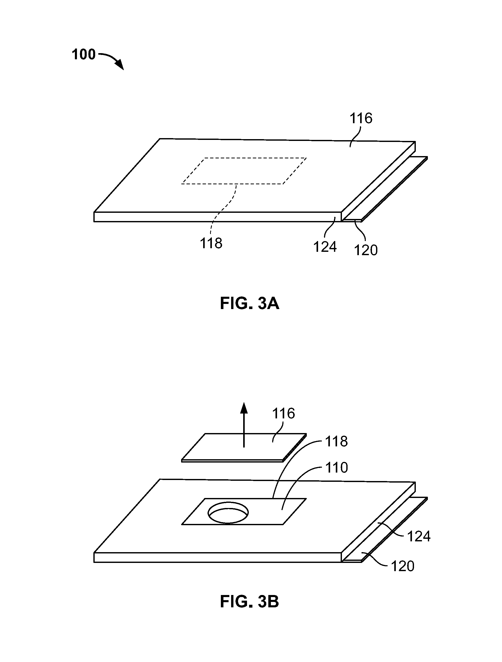
[0044] Turning to FIG. 3A, the adhesive patch 100 is shown prior to being fixed to the drug delivery device 10. The adhesive patch 100 has an upper surface 110 (not visible in FIG. 3A) covered by a bacteria impermeable upper liner 116 and a lower surface 112 (not visible in FIG. 3A) covered by a bacterial impermeable lower liner 120. As will be described more fully below, a bacteria impermeable sterility margin 124 surrounds an edge surface 114 (see, FIG. 4; not visible in FIG. 3A) extending between the upper surface 110 and the lower surface 112. The upper liner 116 has a first perimeter 118 surrounding a portion of the adhesive patch 100 that will be adhered to the drug delivery device 10. The upper liner 116 is pre-cut at the first perimeter 118. In some arrangements, the upper liner 116 may be pre-cut at the first perimeter 118 in a perforated manner. In some arrangements, the first perimeter 118 does not extend beyond the outer boundary 132 of the bottom wall 25 (shown in FIG. 2) in order to prevent exposure of adhesive on upper surface 110.
[0045] As shown in FIG. 3B, to assemble the adhesive patch 100 to the drug delivery device 10, the portion of the upper liner 116 that is within the first perimeter 118 is removed. A hole 108 in the adhesive patch 100 is then visible and exposed. Turning to FIG. 3C, the hole 108 is aligned with the insertion mechanism 12 (shown in FIG. 1) of the drug delivery device 100 in order to allow the delivery member (shown in FIG. 1) of the insertion mechanism 12 to extend to a deployed position without having to penetrate the adhesive patch 100. The portion of the area 102 configured to be adhered to the drug delivery device 100 is then adhered to a sub-assembly of the drug delivery device 10. For purposes of this disclosure, a "sub-assembly" may refer to a portion or the entirety of the drug delivery device 10. The adhesion is completed such that the portion of the area 102 adhered to the drug delivery device 100 provides a seal to prevent bacteria from entering hole 108. The adhesive patch 100 and the sub-assembly of the drug delivery device 10 are then sterilized. The sub-assembly of the drug delivery device 100 comprises a container (shown in FIG. 1), which is filled in a sterile fill line. After that, all remaining parts of the drug delivery device 10 may be connected to the sub-assembly in an environment that may or may not necessarily be sterile. While the patch 100 has been described as including the hole 108, other configurations of the patch 100 may not include the hole 108 and instead the delivery member may penetrate directly through the patch 100.
[0046] FIG. 3D shows the adhesive patch 100 and drug delivery device 10 of FIGS. 3A-3C in an exploded view after assembly has been completed for purposes of shipment and storage but prior to use by a patient or caregiver. At the top is the drug delivery device 10. Below the drug delivery device 10 is the upper liner 116 with the portion of the upper liner 116 within the first perimeter 118 removed. The adhesive patch 100 having area 102 within outer perimeter 104 is shown below the upper liner 116. The adhesive patch 100 has an upper surface 110, a lower surface 112, and an edge surface 114 (see FIG. 4; not visible in FIG. 3D). The hole 108 is provided in the area 102 of the adhesive patch 100 in this version. Below that, the lower liner 120 is shown. The sterility margin 124 is a frame-like structure that surrounds the edge surface 114 and includes a sealing edge 115 (see, e.g., FIGS. 3D and 4) that forms a seal therewith to reduce and/or prevent contamination. In the arrangement depicted in FIG. 3D, the sterility margin 124 is attached to and is integral with the patch 100 by way of a perforated seam or other detachable coupling system connecting the edge surface 114 and the sealing surface 115. In other versions, the sealing edge 115 of the sterility margin 124 may not be physically coupled to the edge surface 114, but rather, simply abutted against the edge surface 114 to protect the edge surface 114 from contamination or exposure to contaminants until after the margin 124 has been removed. In FIG. 3D, the contact between the sterility margin 124 and the upper liner 116 and also the contact between the sterility margin 124 and the lower liner 120 are bacteria impermeable and detachable. In other arrangements discussed below relative to FIGS. 4, 5A, and 5B, the sterility margin 124 can be integral with or permanently attached to either the upper liner 116 or the lower liner 120. The sterility margin 124 generally has a width W of at least 2 mm in order to facilitate its removal. Sterility margin 124 can be simply the outer area of the adhesive patch 100 that is precut or perforated at a width W of at least 2 mm.
[0047] FIG. 4 shows one version of the lower liner 120 and sterility margin 124, whereby they can be removed at the same time as the drug delivery device 110 is prepared for use. In this arrangement, the sterility margin 124 is attached to or integral with the lower liner 120. For example, the sterility margin 124 may be bonded with adhesive, ultrasonically welded, or otherwise connected to the lower liner 120. In one version, the sterility margin 124 may be constructed as a single unit and of the same material as the lower liner 120. The lower liner 120 and the sterility margin 124 are pulled away from the adhesive patch 100 as a unitary piece and with sufficient force to break any connection or attraction between the sealing edge 115 of the sterility margin 124 and the edge surface 114, thereby exposing the uncontaminated edge surface 114. In other arrangements, such as that depicted in FIG. 3D, the lower liner 120 and the sterility margin 124 may be removed separately because the sterility margin 124 is not part of the lower liner 120 but part of the patch 100. Once the lower liner 120 is removed, the uncontaminated lower surface 112 (not visible in FIG. 4) of the adhesive patch 100 is exposed. Once the sterility margin 124 is removed, the uncontaminated edge surface 114 of the adhesive patch 100 is exposed. Adhesive on the lower surface 112 of the patch 100 enables the drug delivery device 10 to be secured to the patient's tissue 11 (as shown in FIG. 1).
[0048] FIGS. 5A-5B show an alternative arrangement in which the sterility margin 124 is attached to or integral with the upper liner 116. The sterility margin 124 may, for example, be bonded with adhesive, ultrasonically welded, or otherwise connected to the upper liner 116. With this arrangement, two steps are necessary to prepare the delivery device 10 for use. First, as shown in FIG. 5A, the lower liner 120 can be pulled away from the adhesive patch 100 in order to expose the lower surface (not visible in FIG. 5A) of the adhesive patch 100. Second, as shown in FIG. 5B, the upper liner 116 and sealing edge 115 of the sterility margin 124 can be pulled away from the adhesive patch 100 and over the drug delivery device 10. In other versions, the upper liner 116 and sterility margin 124 can be removed before removing the lower liner 120. Regardless, once the sterility margin 124 and upper liner 116 are removed, the edge surface 114 and upper surface 110 of the adhesive patch 100 are exposed. Adhesive on the exposed lower surface 112 enables the drug delivery device 100 to be secured to the patient's tissue 11 (as shown in FIG. 1).
[0049] Drug Information
[0050] As mentioned above, the container may be filled with a drug. This drug may be any one or combination of the drugs listed below, with the caveat that the following list should neither be considered to be all inclusive nor limiting.
[0051] For example, the syringe may be filled with colony stimulating factors, such as granulocyte colony-stimulating factor (G-CSF). Such G-CSF agents include, but are not limited to, Neupogen.RTM. (filgrastim) and Neulasta.RTM. (pegfilgrastim). In various other embodiments, the syringe may be used with various pharmaceutical products, such as an erythropoiesis stimulating agent (ESA), which may be in a liquid or a lyophilized form. An ESA is any molecule that stimulates erythropoiesis, such as Epogen.RTM. (epoetin alfa), Aranesp.RTM. (darbepoetin alfa), Dynepo.RTM. (epoetin delta), Mircera.RTM. (methyoxy polyethylene glycol-epoetin beta), Hematide.RTM., MRK-2578, INS-22, Retacrit.RTM. (epoetin zeta), Neorecormon.RTM. (epoetin beta), Silapo.RTM. (epoetin zeta), Binocrit.RTM. (epoetin alfa), epoetin alfa Hexal, Abseamed.RTM. (epoetin alfa), Ratioepo.RTM. (epoetin theta), Eporatio.RTM. (epoetin theta), Biopoin.RTM. (epoetin theta), epoetin alfa, epoetin beta, epoetin zeta, epoetin theta, and epoetin delta, as well as the molecules or variants or analogs thereof as disclosed in the following patents or patent applications, each of which is herein incorporated by reference in its entirety: U.S. Pat. Nos. 4,703,008; 5,441,868; 5,547,933; 5,618,698; 5,621,080; 5,756,349; 5,767,078; 5,773,569; 5,955,422; 5,986,047; 6,583,272; 7,084,245; and 7,271,689; and PCT Publication Nos. WO 91/05867; WO 95/05465; WO 96/40772; WO 00/24893; WO 01/81405; and WO 2007/136752.
[0052] An ESA can be an erythropoiesis stimulating protein. As used herein, "erythropoiesis stimulating protein" means any protein that directly or indirectly causes activation of the erythropoietin receptor, for example, by binding to and causing dimerization of the receptor. Erythropoiesis stimulating proteins include erythropoietin and variants, analogs, or derivatives thereof that bind to and activate erythropoietin receptor; antibodies that bind to erythropoietin receptor and activate the receptor; or peptides that bind to and activate erythropoietin receptor. Erythropoiesis stimulating proteins include, but are not limited to, epoetin alfa, epoetin beta, epoetin delta, epoetin omega, epoetin iota, epoetin zeta, and analogs thereof, pegylated erythropoietin, carbamylated erythropoietin, mimetic peptides (including EMP1/hematide), and mimetic antibodies. Exemplary erythropoiesis stimulating proteins include erythropoietin, darbepoetin, erythropoietin agonist variants, and peptides or antibodies that bind and activate erythropoietin receptor (and include compounds reported in U.S. Publication Nos. 2003/0215444 and 2006/0040858, the disclosures of each of which is incorporated herein by reference in its entirety) as well as erythropoietin molecules or variants or analogs thereof as disclosed in the following patents or patent applications, which are each herein incorporated by reference in its entirety: U.S. Pat. Nos. 4,703,008; 5,441,868; 5,547,933; 5,618,698; 5,621,080; 5,756,349; 5,767,078; 5,773,569; 5,955,422; 5,830,851; 5,856,298; 5,986,047; 6,030,086; 6,310,078; 6,391,633; 6,583,272; 6,586,398; 6,900,292; 6,750,369; 7,030,226; 7,084,245; and 7,217,689; U.S. Publication Nos. 2002/0155998; 2003/0077753; 2003/0082749; 2003/0143202; 2004/0009902; 2004/0071694; 2004/0091961; 2004/0143857; 2004/0157293; 2004/0175379; 2004/0175824; 2004/0229318; 2004/0248815; 2004/0266690; 2005/0019914; 2005/0026834; 2005/0096461; 2005/0107297; 2005/0107591; 2005/0124045; 2005/0124564; 2005/0137329; 2005/0142642; 2005/0143292; 2005/0153879; 2005/0158822; 2005/0158832; 2005/0170457; 2005/0181359; 2005/0181482; 2005/0192211; 2005/0202538; 2005/0227289; 2005/0244409; 2006/0088906; and 2006/0111279; and PCT Publication Nos. WO 91/05867; WO 95/05465; WO 99/66054; WO 00/24893; WO 01/81405; WO 00/61637; WO 01/36489; WO 02/014356; WO 02/19963; WO 02/20034; WO 02/49673; WO 02/085940; WO 03/029291; WO 2003/055526; WO 2003/084477; WO 2003/094858; WO 2004/002417; WO 2004/002424; WO 2004/009627; WO 2004/024761; WO 2004/033651; WO 2004/035603; WO 2004/043382; WO 2004/101600; WO 2004/101606; WO 2004/101611; WO 2004/106373; WO 2004/018667; WO 2005/001025; WO 2005/001136; WO 2005/021579; WO 2005/025606; WO 2005/032460; WO 2005/051327; WO 2005/063808; WO 2005/063809; WO 2005/070451; WO 2005/081687; WO 2005/084711; WO 2005/103076; WO 2005/100403; WO 2005/092369; WO 2006/50959; WO 2006/02646; and WO 2006/29094.
[0053] Examples of other pharmaceutical products for use with the device may include, but are not limited to, antibodies such as Vectibix.RTM. (panitumumab), Xgeva.TM. (denosumab) and Prolia.TM. (denosamab); other biological agents such as Enbrel.RTM. (etanercept, TNF-receptor/Fc fusion protein, TNF blocker), Neulasta.RTM. (pegfilgrastim, pegylated filgastrim, pegylated G-CSF, pegylated hu-Met-G-CSF), Neupogen.RTM. (filgrastim, G-CSF, hu-MetG-CSF), and Nplate.RTM. (romiplostim); small molecule drugs such as Sensipar.RTM. (cinacalcet). The device may also be used with a therapeutic antibody, a polypeptide, a protein or other chemical, such as an iron, for example, ferumoxytol, iron dextrans, ferric glyconate, and iron sucrose. The pharmaceutical product may be in liquid form, or reconstituted from lyophilized form.
[0054] Among particular illustrative proteins are the specific proteins set forth below, including fusions, fragments, analogs, variants or derivatives thereof:
[0055] OPGL specific antibodies, peptibodies, and related proteins, and the like (also referred to as RANKL specific antibodies, peptibodies and the like), including fully humanized and human OPGL specific antibodies, particularly fully humanized monoclonal antibodies, including but not limited to the antibodies described in PCT Publication No. WO 03/002713, which is incorporated herein in its entirety as to OPGL specific antibodies and antibody related proteins, particularly those having the sequences set forth therein, particularly, but not limited to, those denoted therein: 9H7; 18B2; 2D8; 2E11; 16E1; and 22B3, including the OPGL specific antibodies having either the light chain of SEQ ID NO:2 as set forth therein in FIG. 2 and/or the heavy chain of SEQ ID NO:4, as set forth therein in FIG. 4, each of which is individually and specifically incorporated by reference herein in its entirety fully as disclosed in the foregoing publication;
[0056] Myostatin binding proteins, peptibodies, and related proteins, and the like, including myostatin specific peptibodies, particularly those described in U.S. Publication No. 2004/0181033 and PCT Publication No. WO 2004/058988, which are incorporated by reference herein in their entirety particularly in parts pertinent to myostatin specific peptibodies, including but not limited to peptibodies of the mTN8-19 family, including those of SEQ ID NOS:305-351, including TN8-19-1 through TN8-19-40, TN8-19 con1 and TN8-19 con2; peptibodies of the mL2 family of SEQ ID NOS:357-383; the mL15 family of SEQ ID NOS:384-409; the mL17 family of SEQ ID NOS:410-438; the mL20 family of SEQ ID NOS:439-446; the mL21 family of SEQ ID NOS:447-452; the mL24 family of SEQ ID NOS:453-454; and those of SEQ ID NOS:615-631, each of which is individually and specifically incorporated by reference herein in their entirety fully as disclosed in the foregoing publication;
[0057] IL-4 receptor specific antibodies, peptibodies, and related proteins, and the like, particularly those that inhibit activities mediated by binding of IL-4 and/or IL-13 to the receptor, including those described in PCT Publication No. WO 2005/047331 or PCT Application No. PCT/US2004/37242 and in U.S. Publication No. 2005/112694, which are incorporated herein by reference in their entirety particularly in parts pertinent to IL-4 receptor specific antibodies, particularly such antibodies as are described therein, particularly, and without limitation, those designated therein: L1H1; L1H2; L1H3; L1H4; L1H5; L1H6; L1H7; L1H8; L1H9; L1H10; L1H11; L2H1; L2H2; L2H3; L2H4; L2H5; L2H6; L2H7; L2H8; L2H9; L2H10; L2H11; L2H12; L2H13; L2H14; L3H1; L4H1; L5H1; L6H1, each of which is individually and specifically incorporated by reference herein in its entirety fully as disclosed in the foregoing publication;
[0058] Interleukin 1-receptor 1 ("IL1-R1") specific antibodies, peptibodies, and related proteins, and the like, including but not limited to those described in U.S. Publication No. 2004/097712, which is incorporated herein by reference in its entirety in parts pertinent to IL1-R1 specific binding proteins, monoclonal antibodies in particular, especially, without limitation, those designated therein: 15CA, 26F5, 27F2, 24E12, and 10H7, each of which is individually and specifically incorporated by reference herein in its entirety fully as disclosed in the aforementioned publication;
[0059] Ang2 specific antibodies, peptibodies, and related proteins, and the like, including but not limited to those described in PCT Publication No. WO 03/057134 and U.S. Publication No. 2003/0229023, each of which is incorporated herein by reference in its entirety particularly in parts pertinent to Ang2 specific antibodies and peptibodies and the like, especially those of sequences described therein and including but not limited to: L1(N); L1(N) WT; L1(N) 1K WT; 2.times.L1(N); 2.times.L1(N) WT; Con4 (N), Con4 (N) 1K WT, 2.times.Con4 (N) 1K; L1C; L1C 1K; 2.times.L1C; Con4C; Con4C 1K; 2.times.Con4C 1K; Con4-L1 (N); Con4-L1C; TN-12-9 (N); C17 (N); TN8-8(N); TN8-14 (N); Con 1 (N), also including anti-Ang 2 antibodies and formulations such as those described in PCT Publication No. WO 2003/030833 which is incorporated herein by reference in its entirety as to the same, particularly Ab526; Ab528; Ab531; Ab533; Ab535; Ab536; Ab537; Ab540; Ab543; Ab544; Ab545; Ab546; A551; Ab553; Ab555; Ab558; Ab559; Ab565; AbF1AbFD; AbFE; AbFJ; AbFK; AbG1D4; AbGC1E8; AbH1C12; AbIA1; AbIF; AbIK, AbIP; and AbIP, in their various permutations as described therein, each of which is individually and specifically incorporated by reference herein in its entirety fully as disclosed in the foregoing publication;
[0060] NGF specific antibodies, peptibodies, and related proteins, and the like including, in particular, but not limited to those described in U.S. Publication No. 2005/0074821 and U.S. Pat. No. 6,919,426, which are incorporated herein by reference in their entirety particularly as to NGF-specific antibodies and related proteins in this regard, including in particular, but not limited to, the NGF-specific antibodies therein designated 4D4, 4G6, 6H9, 7H2, 14D10 and 14D11, each of which is individually and specifically incorporated by reference herein in its entirety fully as disclosed in the foregoing publication;
[0061] CD22 specific antibodies, peptibodies, and related proteins, and the like, such as those described in U.S. Pat. No. 5,789,554, which is incorporated herein by reference in its entirety as to CD22 specific antibodies and related proteins, particularly human CD22 specific antibodies, such as but not limited to humanized and fully human antibodies, including but not limited to humanized and fully human monoclonal antibodies, particularly including but not limited to human CD22 specific IgG antibodies, such as, for instance, a dimer of a human-mouse monoclonal hLL2 gamma-chain disulfide linked to a human-mouse monoclonal hLL2 kappa-chain, including, but limited to, for example, the human CD22 specific fully humanized antibody in Epratuzumab, CAS registry number 501423-23-0;
[0062] IGF-1 receptor specific antibodies, peptibodies, and related proteins, and the like, such as those described in PCT Publication No. WO 06/069202, which is incorporated herein by reference in its entirety as to IGF-1 receptor specific antibodies and related proteins, including but not limited to the IGF-1 specific antibodies therein designated L1H1, L2H2, L3H3, L4H4, L5H5, L6H6, L7H7, L8H8, L9H9, L10H10, L11H11, L12H12, L13H13, L14H14, L15H15, L16H16, L17H17, L18H18, L19H19, L20H20, L21H21, L22H22, L23H23, L24H24, L25H25, L26H26, L27H27, L28H28, L29H29, L30H30, L31H31, L32H32, L33H33, L34H34, L35H35, L36H36, L37H37, L38H38, L39H39, L40H40, L41H41, L42H42, L43H43, L44H44, L45H45, L46H46, L47H47, L48H48, L49H49, L50H50, L51H51, L52H52, and IGF-1R-binding fragments and derivatives thereof, each of which is individually and specifically incorporated by reference herein in its entirety fully as disclosed in the foregoing publication;
[0063] Also among non-limiting examples of anti-IGF-1R antibodies for use in the methods and compositions of the present disclosure are each and all of those described in:
[0064] (i) U.S. Publication No. 2006/0040358 (published Feb. 23, 2006), 2005/0008642 (published Jan. 13, 2005), 2004/0228859 (published Nov. 18, 2004), including but not limited to, for instance, antibody 1A (DSMZ Deposit No. DSM ACC 2586), antibody 8 (DSMZ Deposit No. DSM ACC 2589), antibody 23 (DSMZ Deposit No. DSM ACC 2588) and antibody 18 as described therein;
[0065] (ii) PCT Publication No. WO 06/138729 (published Dec. 28, 2006) and WO 05/016970 (published Feb. 24, 2005), and Lu et al. (2004), J. Biol. Chem. 279:2856-2865, including but not limited to antibodies 2F8, A12, and IMC-A12 as described therein;
[0066] (iii) PCT Publication No. WO 07/012614 (published Feb. 1, 2007), WO 07/000328 (published Jan. 4, 2007), WO 06/013472 (published Feb. 9, 2006), WO 05/058967 (published Jun. 30, 2005), and WO 03/059951 (published Jul. 24, 2003);
[0067] (iv) U.S. Publication No. 2005/0084906 (published Apr. 21, 2005), including but not limited to antibody 7C10, chimaeric antibody 07010, antibody h7C10, antibody 7H2M, chimaeric antibody *7C10, antibody GM 607, humanized antibody 7C10 version 1, humanized antibody 7C10 version 2, humanized antibody 7C10 version 3, and antibody 7H2HM, as described therein;
[0068] (v) U.S. Publication Nos. 2005/0249728 (published Nov. 10, 2005), 2005/0186203 (published Aug. 25, 2005), 2004/0265307 (published Dec. 30, 2004), and 2003/0235582 (published Dec. 25, 2003) and Maloney et al. (2003), Cancer Res. 63:5073-5083, including but not limited to antibody EM164, resurfaced EM164, humanized EM164, huEM164 v1.0, huEM164 v1.1, huEM164 v1.2, and huEM164 v1.3 as described therein;
[0069] (vi) U.S. Pat. No. 7,037,498 (issued May 2, 2006), U.S. Publication Nos. 2005/0244408 (published Nov. 30, 2005) and 2004/0086503 (published May 6, 2004), and Cohen, et al. (2005), Clinical Cancer Res. 11:2063-2073, e.g., antibody CP-751,871, including but not limited to each of the antibodies produced by the hybridomas having the ATCC accession numbers PTA-2792, PTA-2788, PTA-2790, PTA-2791, PTA-2789, PTA-2793, and antibodies 2.12.1, 2.13.2, 2.14.3, 3.1.1, 4.9.2, and 4.17.3, as described therein;
[0070] (vii) U.S. Publication Nos. 2005/0136063 (published Jun. 23, 2005) and 2004/0018191 (published Jan. 29, 2004), including but not limited to antibody 19D12 and an antibody comprising a heavy chain encoded by a polynucleotide in plasmid 15H12/19D12 HCA (.gamma.4), deposited at the ATCC under number PTA-5214, and a light chain encoded by a polynucleotide in plasmid 15H12/19D12 LCF (.kappa.), deposited at the ATCC under number PTA-5220, as described therein; and
[0071] (viii) U.S. Publication No. 2004/0202655 (published Oct. 14, 2004), including but not limited to antibodies PINT-6A1, PINT-7A2, PINT-7A4, PINT-7A5, PINT-7A6, PINT-8A1, PINT-9A2, PINT-11A1, PINT-11A2, PINT-11A3, PINT-11A4, PINT-11A5, PINT-11A7, PINT-11A12, PINT-12A1, PINT-12A2, PINT-12A3, PINT-12A4, and PINT-12A5, as described therein; each and all of which are herein incorporated by reference in their entireties, particularly as to the aforementioned antibodies, peptibodies, and related proteins and the like that target IGF-1 receptors;
[0072] B-7 related protein 1 specific antibodies, peptibodies, related proteins and the like ("B7RP-1," also is referred to in the literature as B7H2, ICOSL, B7h, and CD275), particularly B7RP-specific fully human monoclonal IgG2 antibodies, particularly fully human IgG2 monoclonal antibody that binds an epitope in the first immunoglobulin-like domain of B7RP-1, especially those that inhibit the interaction of B7RP-1 with its natural receptor, ICOS, on activated T cells in particular, especially, in all of the foregoing regards, those disclosed in U.S. Publication No. 2008/0166352 and PCT Publication No. WO 07/011941, which are incorporated herein by reference in their entireties as to such antibodies and related proteins, including but not limited to antibodies designated therein as follow: 16H (having light chain variable and heavy chain variable sequences SEQ ID NO:1 and SEQ ID NO:7 respectively therein); 5D (having light chain variable and heavy chain variable sequences SEQ ID NO:2 and SEQ ID NO:9 respectively therein); 2H (having light chain variable and heavy chain variable sequences SEQ ID NO:3 and SEQ ID NO:10 respectively therein); 43H (having light chain variable and heavy chain variable sequences SEQ ID NO:6 and SEQ ID NO:14 respectively therein); 41H (having light chain variable and heavy chain variable sequences SEQ ID NO:5 and SEQ ID NO:13 respectively therein); and 15H (having light chain variable and heavy chain variable sequences SEQ ID NO:4 and SEQ ID NO:12 respectively therein), each of which is individually and specifically incorporated by reference herein in its entirety fully as disclosed in the foregoing publication;
[0073] IL-15 specific antibodies, peptibodies, and related proteins, and the like, such as, in particular, humanized monoclonal antibodies, particularly antibodies such as those disclosed in U.S. Publication Nos. 2003/0138421; 2003/023586; and 2004/0071702; and U.S. Pat. No. 7,153,507, each of which is incorporated herein by reference in its entirety as to IL-15 specific antibodies and related proteins, including peptibodies, including particularly, for instance, but not limited to, HuMax IL-15 antibodies and related proteins, such as, for instance, 14667;
[0074] IFN gamma specific antibodies, peptibodies, and related proteins and the like, especially human IFN gamma specific antibodies, particularly fully human anti-IFN gamma antibodies, such as, for instance, those described in U.S. Publication No. 2005/0004353, which is incorporated herein by reference in its entirety as to IFN gamma specific antibodies, particularly, for example, the antibodies therein designated 1118; 1118*; 1119; 1121; and 1121*. The entire sequences of the heavy and light chains of each of these antibodies, as well as the sequences of their heavy and light chain variable regions and complementarity determining regions, are each individually and specifically incorporated by reference herein in its entirety fully as disclosed in the foregoing publication and in Thakur et al. (1999), Mol. Immunol. 36:1107-1115. In addition, description of the properties of these antibodies provided in the foregoing publication is also incorporated by reference herein in its entirety. Specific antibodies include those having the heavy chain of SEQ ID NO:17 and the light chain of SEQ ID NO:18; those having the heavy chain variable region of SEQ ID NO:6 and the light chain variable region of SEQ ID NO:8; those having the heavy chain of SEQ ID NO:19 and the light chain of SEQ ID NO:20; those having the heavy chain variable region of SEQ ID NO:10 and the light chain variable region of SEQ ID NO:12; those having the heavy chain of SEQ ID NO:32 and the light chain of SEQ ID NO:20; those having the heavy chain variable region of SEQ ID NO:30 and the light chain variable region of SEQ ID NO:12; those having the heavy chain sequence of SEQ ID NO:21 and the light chain sequence of SEQ ID NO:22; those having the heavy chain variable region of SEQ ID NO:14 and the light chain variable region of SEQ ID NO:16; those having the heavy chain of SEQ ID NO:21 and the light chain of SEQ ID NO:33; and those having the heavy chain variable region of SEQ ID NO:14 and the light chain variable region of SEQ ID NO:31, as disclosed in the foregoing publication. A specific antibody contemplated is antibody 1119 as disclosed in the foregoing U.S. publication and having a complete heavy chain of SEQ ID NO:17 as disclosed therein and having a complete light chain of SEQ ID NO:18 as disclosed therein;
[0075] TALL-1 specific antibodies, peptibodies, and the related proteins, and the like, and other TALL specific binding proteins, such as those described in U.S. Publication Nos. 2003/0195156 and 2006/0135431, each of which is incorporated herein by reference in its entirety as to TALL-1 binding proteins, particularly the molecules of Tables 4 and 5B, each of which is individually and specifically incorporated by reference herein in its entirety fully as disclosed in the foregoing publications;
[0076] Parathyroid hormone ("PTH") specific antibodies, peptibodies, and related proteins, and the like, such as those described in U.S. Pat. No. 6,756,480, which is incorporated herein by reference in its entirety, particularly in parts pertinent to proteins that bind PTH;
[0077] Thrombopoietin receptor ("TPO-R") specific antibodies, peptibodies, and related proteins, and the like, such as those described in U.S. Pat. No. 6,835,809, which is herein incorporated by reference in its entirety, particularly in parts pertinent to proteins that bind TPO-R;
[0078] Hepatocyte growth factor ("HGF") specific antibodies, peptibodies, and related proteins, and the like, including those that target the HGF/SF:cMet axis (HGF/SF:c-Met), such as the fully human monoclonal antibodies that neutralize hepatocyte growth factor/scatter (HGF/SF) described in U.S. Publication No. 2005/0118643 and PCT Publication No. WO 2005/017107, huL2G7 described in U.S. Pat. No. 7,220,410 and OA-5d5 described in U.S. Pat. Nos. 5,686,292 and 6,468,529 and in PCT Publication No. WO 96/38557, each of which is incorporated herein by reference in its entirety, particularly in parts pertinent to proteins that bind HGF;
[0079] TRAIL-R2 specific antibodies, peptibodies, related proteins and the like, such as those described in U.S. Pat. No. 7,521,048, which is herein incorporated by reference in its entirety, particularly in parts pertinent to proteins that bind TRAIL-R2;
[0080] Activin A specific antibodies, peptibodies, related proteins, and the like, including but not limited to those described in U.S. Publication No. 2009/0234106, which is herein incorporated by reference in its entirety, particularly in parts pertinent to proteins that bind Activin A;
[0081] TGF-beta specific antibodies, peptibodies, related proteins, and the like, including but not limited to those described in U.S. Pat. No. 6,803,453 and U.S. Publication No. 2007/0110747, each of which is herein incorporated by reference in its entirety, particularly in parts pertinent to proteins that bind TGF-beta;
[0082] Amyloid-beta protein specific antibodies, peptibodies, related proteins, and the like, including but not limited to those described in PCT Publication No. WO 2006/081171, which is herein incorporated by reference in its entirety, particularly in parts pertinent to proteins that bind amyloid-beta proteins. One antibody contemplated is an antibody having a heavy chain variable region comprising SEQ ID NO:8 and a light chain variable region having SEQ ID NO:6 as disclosed in the foregoing publication;
[0083] c-Kit specific antibodies, peptibodies, related proteins, and the like, including but not limited to those described in U.S. Publication No. 2007/0253951, which is incorporated herein by reference in its entirety, particularly in parts pertinent to proteins that bind c-Kit and/or other stem cell factor receptors;
[0084] OX40L specific antibodies, peptibodies, related proteins, and the like, including but not limited to those described in U.S. Publication No. 2006/0002929, which is incorporated herein by reference in its entirety, particularly in parts pertinent to proteins that bind OX40L and/or other ligands of the OX40 receptor; and
[0085] Other exemplary proteins, including Activase.RTM. (alteplase, tPA); Aranesp.RTM. (darbepoetin alfa); Epogen.RTM. (epoetin alfa, or erythropoietin); GLP-1, Avonex.RTM. (interferon beta-1a); Bexxar.RTM. (tositumomab, anti-CD22 monoclonal antibody); Betaseron.RTM. (interferon-beta); Campath.RTM. (alemtuzumab, anti-CD52 monoclonal antibody); Dynepo.RTM. (epoetin delta); Velcade.RTM. (bortezomib); MLN0002 (anti-.alpha.4.beta.7 mAb); MLN1202 (anti-CCR2 chemokine receptor mAb); Enbrel.RTM. (etanercept, TNF-receptor/Fc fusion protein, TNF blocker); Eprex.RTM. (epoetin alfa); Erbitux.RTM. (cetuximab, anti-EGFR/HER1/c-ErbB-1); Genotropin.RTM. (somatropin, Human Growth Hormone); Herceptin.RTM. (trastuzumab, anti-HER2/neu (erbB2) receptor mAb); Humatrope.RTM. (somatropin, Human Growth Hormone); Humira.RTM. (adalimumab); insulin in solution; Infergen.RTM. (interferon alfacon-1); Natrecor.RTM. (nesiritide; recombinant human B-type natriuretic peptide (hBNP); Kineret.RTM. (anakinra); Leukine.RTM. (sargamostim, rhuGM-CSF); LymphoCide.RTM. (epratuzumab, anti-CD22 mAb); Benlysta.TM. (lymphostat B, belimumab, anti-BlyS mAb); Metalyse.RTM. (tenecteplase, t-PA analog); Mircera.RTM. (methoxy polyethylene glycol-epoetin beta); Mylotarg.RTM. (gemtuzumab ozogamicin); Raptiva.RTM. (efalizumab); Cimzia.RTM. (certolizumab pegol, CDP 870); Soliris.TM. (eculizumab); pexelizumab (anti-C5 complement); Numax.RTM. (MEDI-524); Lucentis.RTM. (ranibizumab); Panorex.RTM. (17-1A, edrecolomab); Trabio.RTM. (lerdelimumab); TheraCim hR3 (nimotuzumab); Omnitarg (pertuzumab, 2C4); Osidem.RTM. (IDM-1); OvaRex.RTM. (B43.13); Nuvion.RTM. (visilizumab); cantuzumab mertansine (huC242-DM1); NeoRecormon.RTM. (epoetin beta); Neumega.RTM. (oprelvekin, human interleukin-11); Neulasta.RTM. (pegylated filgastrim, pegylated G-CSF, pegylated hu-Met-G-CSF); Neupogen.RTM. (filgrastim, G-CSF, hu-MetG-CSF); Orthoclone OKT3.RTM. (muromonab-CD3, anti-CD3 monoclonal antibody); Procrit.RTM. (epoetin alfa); Remicade.RTM. (infliximab, anti-TNF.alpha. monoclonal antibody); Reopro.RTM. (abciximab, anti-GP IIb/IIia receptor monoclonal antibody); Actemra.RTM. (anti-IL6 Receptor mAb); Avastin.RTM. (bevacizumab), HuMax-CD4 (zanolimumab); Rituxan.RTM. (rituximab, anti-CD20 mAb); Tarceva.RTM. (erlotinib); Roferon-A.RTM.-(interferon alfa-2a); Simulect.RTM. (basiliximab); Prexige.RTM. (lumiracoxib); Synagis.RTM. (palivizumab); 146B7-CHO (anti-IL15 antibody, see U.S. Pat. No. 7,153,507); Tysabri.RTM. (natalizumab, anti-.alpha.4integrin mAb); Valortim.RTM. (MDX-1303, anti-B. anthracis protective antigen mAb); ABthrax.TM.; Vectibix.RTM. (panitumumab); Xolair.RTM. (omalizumab); ETI211 (anti-MRSA mAb); IL-1 trap (the Fc portion of human IgG1 and the extracellular domains of both IL-1 receptor components (the Type I receptor and receptor accessory protein)); VEGF trap (Ig domains of VEGFR1 fused to IgG1 Fc); Zenapax.RTM. (daclizumab); Zenapax.RTM. (daclizumab, anti-IL-2R.alpha. mAb); Zevalin.RTM. (ibritumomab tiuxetan); Zetia.RTM. (ezetimibe); Orencia.RTM. (atacicept, TACI-Ig); anti-CD80 monoclonal antibody (galiximab); anti-CD23 mAb (lumiliximab); BR2-Fc (huBR3/huFc fusion protein, soluble BAFF antagonist); CNTO 148 (golimumab, anti-TNF.alpha. mAb); HGS-ETR1 (mapatumumab; human anti-TRAIL Receptor-1 mAb); HuMax-CD20 (ocrelizumab, anti-CD20 human mAb); HuMax-EGFR (zalutumumab); M200 (volociximab, anti-.alpha.5.beta.1 integrin mAb); MDX-010 (ipilimumab, anti-CTLA-4 mAb and VEGFR-1 (IMC-18F1); anti-BR3 mAb; anti-C. difficile Toxin A and Toxin B C mAbs MDX-066 (CDA-1) and MDX-1388); anti-CD22 dsFv-PE38 conjugates (CAT-3888 and CAT-8015); anti-CD25 mAb (HuMax-TAC); anti-CD3 mAb (NI-0401); adecatumumab; anti-CD30 mAb (MDX-060); MDX-1333 (anti-IFNAR); anti-CD38 mAb (HuMax CD38); anti-CD40L mAb; anti-Cripto mAb; anti-CTGF Idiopathic Pulmonary Fibrosis Phase I Fibrogen (FG-3019); anti-CTLA4 mAb; anti-eotaxin1 mAb (CAT-213); anti-FGF8 mAb; anti-ganglioside GD2 mAb; anti-ganglioside GM2 mAb; anti-GDF-8 human mAb (MYO-029); anti-GM-CSF Receptor mAb (CAM-3001); anti-HepC mAb (HuMax HepC); anti-IFN.alpha. mAb (MEDI-545, MDX-1103); anti-IGF1R mAb; anti-IGF-1R mAb (HuMax-Inflam); anti-IL12 mAb (ABT-874); anti-IL12/1L23 mAb (CNTO 1275); anti-IL13 mAb (CAT-354); anti-IL2Ra mAb (HuMax-TAC); anti-IL5 Receptor mAb; anti-integrin receptors mAb (MDX-018, CNTO 95); anti-IP10 Ulcerative Colitis mAb (MDX-1100); anti-LLY antibody; BMS-66513; anti-Mannose Receptor/hCG.beta. mAb (MDX-1307); anti-mesothelin dsFv-PE38 conjugate (CAT-5001); anti-PD1mAb (MDX-1106 (ONO-4538)); anti-PDGFR.alpha. antibody (IMC-3G3); anti-TG.beta. mAb (GC-1008); anti-TRAIL Receptor-2 human mAb (HGS-ETR2); anti-TWEAK mAb; anti-VEGFR/Flt-1 mAb; anti-ZP3 mAb (HuMax-ZP3); NVS Antibody #1; and NVS Antibody #2.
[0086] Also included can be a sclerostin antibody, such as but not limited to romosozumab, blosozumab, or BPS 804 (Novartis). Further included can be therapeutics such as rilotumumab, bixalomer, trebananib, ganitumab, conatumumab, motesanib diphosphate, brodalumab, vidupiprant, panitumumab, denosumab, NPLATE, PROLIA, VECTIBIX or XGEVA. Additionally, included in the device can be a monoclonal antibody (IgG) that binds human Proprotein Convertase Subtilisin/Kexin Type 9 (PCSK9). Such PCSK9 specific antibodies include, but are not limited to, Repatha.RTM. (evolocumab) and Praluent.RTM. (alirocumab), as well as molecules, variants, analogs or derivatives thereof as disclosed in the following patents or patent applications, each of which is herein incorporated by reference in its entirety for all purposes: U.S. Pat. Nos. 8,030,547, 8,563,698, 8,829,165, 8,859,741, 8,871,913, 8,871,914, 8,883,983, 8,889,834, 8,981,064, 9,056,915, 8,168,762, 9,045,547, 8,030,457, 8,030,457, 8,829,165, 8,981,064, 8,030,457, U.S. Publication No. 2013/0064825, U.S. Patent Application Publication No. 2012/0093818, U.S. Patent Application Publication No. 2013/0079502, U.S. Patent Application Publication No. 2014/0357850, U.S. Patent Application Publication No. 2011/0027287, U.S. Patent Application Publication No. 2014/0357851, U.S. Patent Application Publication No. 2014/0357854, U.S. Patent Application Publication No. 2015/0031870, U.S. Patent Application Publication No. 2013/0085265, U.S. Patent Application Publication No. 2013/0079501, U.S. Patent Application Publication No. 2012/0213797, U.S. Patent Application Publication No. 2012/0251544, U.S. Patent Application Publication No. 2013/0072665, U.S. Patent Application Publication No. 2013/0058944, U.S. Patent Application Publication No. 2013/0052201, U.S. Patent Application Publication No. 2012/0027765, U.S. Patent Application Publication No. 2015/0087819, U.S. Patent Application Publication No. 2011/0117011, U.S. Patent Application Publication No. 2015/0004174, U.S. Provisional Patent Application No. 60/957,668, U.S. Provisional Patent Application No. 61/008,965, U.S. Provisional Patent Application No. 61/010,630, U.S. Provisional Patent Application No. 61/086,133, U.S. Provisional Patent Application No. 61/125,304, U.S. Provisional Patent Application No. 61/798,970, U.S. Provisional Patent Application No. 61/841,039, U.S. Provisional Patent Application No. 62/002,623, U.S. Provisional Patent Application No. 62/024,399, U.S. Provisional Patent Application No. 62/019,729, U.S. Provisional Patent Application No. 62/067,637, U.S. patent application Ser. No. 14/777,371, International Patent Application No. PCT/US2013/048714, International Patent Application No. PCT/US2015/040211, International Patent Application No. PCT/US2015/056972, International Patent Application Publication No. WO/2008/057457, International Patent Application Publication No. WO/2008/057458, International Patent Application Publication No. WO/2008/057459, International Patent Application Publication No. WO/2008/063382, International Patent Application Publication No. WO/2008/133647, International Patent Application Publication No. WO/2009/100297, International Patent Application Publication No. WO/2009/100318, International Patent Application Publication No. WO/2011/037791, International Patent Application Publication No. WO/2011/053759, International Patent Application Publication No. WO/2011/053783, International Patent Application Publication No. WO/2008/125623, International Patent Application Publication No. WO/2011/072263, International Patent Application Publication No. WO/2009/055783, International Patent Application Publication No. WO/2012/0544438, International Patent Application Publication No. WO/2010/029513, International Patent Application Publication No. WO/2011/111007, International Patent Application Publication No. WO/2010/077854, International Patent Application Publication No. WO/2012/088313, International Patent Application Publication No. WO/2012/101251, International Patent Application Publication No. WO/2012/101252, International Patent Application Publication No. WO/2012/101253, International Patent Application Publication No. WO/2012/109530, and International Patent Application Publication No. WO/2001/031007, International Patent Application Publication No. WO/2009/026558, International Patent Application Publication No. WO/2009/131740, International Patent Application Publication No. WO/2013/166448, and International Patent Application Publication No. WO/2014/150983.
[0087] Also included can be talimogene laherparepvec or another oncolytic HSV for the treatment of melanoma or other cancers. Examples of oncolytic HSV include, but are not limited to talimogene laherparepvec (U.S. Pat. Nos. 7,223,593 and 7,537,924); OncoVEXGALV/CD (U.S. Pat. No. 7,981,669); OrienX010 (Lei et al. (2013), World J. Gastroenterol., 19:5138-5143); G207, 1716; NV1020; NV12023; NV1034 and NV1042 (Vargehes et al. (2002), Cancer Gene Ther., 9(12):967-978).
[0088] Also included are TIMPs. TIMPs are endogenous tissue inhibitors of metalloproteinases (TIMPs) and are important in many natural processes. TIMP-3 is expressed by various cells or and is present in the extracellular matrix; it inhibits all the major cartilage-degrading metalloproteases, and may play a role in role in many degradative diseases of connective tissue, including rheumatoid arthritis and osteoarthritis, as well as in cancer and cardiovascular conditions. The amino acid sequence of TIMP-3, and the nucleic acid sequence of a DNA that encodes TIMP-3, are disclosed in U.S. Pat. No. 6,562,596, issued May 13, 2003, the disclosure of which is incorporated by reference herein. Description of TIMP mutations can be found in U.S. Publication No. 2014/0274874 and PCT Publication No. WO 2014/152012.
[0089] Also included are antagonistic antibodies for human calcitonin gene-related peptide (CGRP) receptor and bispecific antibody molecule that target the CGRP receptor and other headache targets. Further information concerning these molecules can be found in PCT Application No. WO 2010/075238.
[0090] Additionally, a bispecific T cell engager antibody (BiTe), e.g. Blinotumomab can be used in the device. Alternatively, included can be an APJ large molecule agonist e.g., apelin or analogues thereof in the device. Information relating to such molecules can be found in PCT Publication No. WO 2014/099984.
[0091] In certain embodiments, the drug comprises a therapeutically effective amount of an anti-thymic stromal lymphopoietin (TSLP) or TSLP receptor antibody. Examples of anti-TSLP antibodies that may be used in such embodiments include, but are not limited to, those described in U.S. Pat. Nos. 7,982,016, and 8,232,372, and U.S. Publication No. 2009/0186022. Examples of anti-TSLP receptor antibodies include, but are not limited to, those described in U.S. Pat. No. 8,101,182. In particularly preferred embodiments, the drug comprises a therapeutically effective amount of the anti-TSLP antibody designated as A5 within U.S. Pat. No. 7,982,016.
[0092] While the present disclosure has been described in connection with various embodiments, it will be understood that the present disclosure is capable of further modifications. The present disclosure is intended to cover any variations, uses, or adaptations of the disclosed subject matter following, in general, the principles of the present disclosure, and including such departures from the present disclosure as, within the known and customary practice within the art to which the present disclosure pertains.
[0093] It is noted that the construction and arrangement of the drug delivery device and its various components and assemblies as shown in the various exemplary embodiments is illustrative only. Although only a few embodiments of the subject matter at issue have been described in detail in the present disclosure, those skilled in the art who review the present disclosure will readily appreciate that many modifications are possible (e.g., variations in sizes, dimensions, structures, shapes and proportions of the various elements, values of parameters, mounting arrangements, use of materials, colors, orientations, etc.) without materially departing from the novel teachings and advantages of the subject matter disclosed herein. For example, elements shown as integrally formed may be constructed of multiple parts or elements, and vice versa. Also, the position of elements may be reversed or otherwise varied, and the nature or number of discrete elements or positions may be altered or varied. Accordingly, all such modifications are intended to be included within the scope of the present disclosure as defined in the appended claims. Furthermore, the order or sequence of any process or method steps may be varied or re-sequenced according to alternative embodiments. Other substitutions, modifications, changes and omissions may be made in the design, operating conditions and arrangement of the various exemplary embodiments without departing from the scope of the present disclosure.
* * * * *
D00000
D00001
D00002
D00003
D00004
D00005
D00006
XML
uspto.report is an independent third-party trademark research tool that is not affiliated, endorsed, or sponsored by the United States Patent and Trademark Office (USPTO) or any other governmental organization. The information provided by uspto.report is based on publicly available data at the time of writing and is intended for informational purposes only.
While we strive to provide accurate and up-to-date information, we do not guarantee the accuracy, completeness, reliability, or suitability of the information displayed on this site. The use of this site is at your own risk. Any reliance you place on such information is therefore strictly at your own risk.
All official trademark data, including owner information, should be verified by visiting the official USPTO website at www.uspto.gov. This site is not intended to replace professional legal advice and should not be used as a substitute for consulting with a legal professional who is knowledgeable about trademark law.