Collapsible And Portable Chair
Grace; Daniel R.
U.S. patent application number 15/975339 was filed with the patent office on 2019-03-21 for collapsible and portable chair. This patent application is currently assigned to GCI Outdoor, Inc.. The applicant listed for this patent is Daniel R. Grace. Invention is credited to Daniel R. Grace.
| Application Number | 20190082846 15/975339 |
| Document ID | / |
| Family ID | 65719629 |
| Filed Date | 2019-03-21 |


View All Diagrams
| United States Patent Application | 20190082846 |
| Kind Code | A1 |
| Grace; Daniel R. | March 21, 2019 |
COLLAPSIBLE AND PORTABLE CHAIR
Abstract
A collapsible and portable chair comprises an articulated chair frame that includes a plurality of pivotally interconnected elongated frame members, as well as a plurality of pivots and joints that define mutually parallel axes about which the chair can be folded from a set-up configuration to a flattened and collapsed configuration. The chair frame includes a front leg assembly, a rear leg assembly, a backrest frame assembly and two independent laterally spaced seat frame members. A fabric panel extends between members of the chair frame to define a seating panel and a backrest panel for receiving a seated user in the set-up condition of the chair. Straps can be provided to facilitate transport of the chair in its folded condition, notable as backpack straps that free up the user's hands so that other objects can be carried along with the folded chair.
| Inventors: | Grace; Daniel R.; (Old Saybrook, CT) | ||||||||||
| Applicant: |
|
||||||||||
|---|---|---|---|---|---|---|---|---|---|---|---|
| Assignee: | GCI Outdoor, Inc. Higganum CT |
||||||||||
| Family ID: | 65719629 | ||||||||||
| Appl. No.: | 15/975339 | ||||||||||
| Filed: | May 9, 2018 |
Related U.S. Patent Documents
| Application Number | Filing Date | Patent Number | ||
|---|---|---|---|---|
| 62503419 | May 9, 2017 | |||
| 62536664 | Jul 25, 2017 | |||
| 62550729 | Aug 28, 2017 | |||
| Current U.S. Class: | 1/1 |
| Current CPC Class: | A47C 4/30 20130101; A47C 4/12 20130101; A47C 4/52 20130101; A47C 1/0265 20130101; A47C 7/622 20180801; A47C 4/283 20130101 |
| International Class: | A47C 4/28 20060101 A47C004/28; A47C 4/30 20060101 A47C004/30 |
Claims
1. A collapsible and portable chair comprising: an articulated chair frame comprising a front leg assembly, a rear leg assembly, a backrest frame assembly, two independent laterally spaced apart seat frame members, and two laterally disposed armrests; a seat defined by a seating panel mounted to the seat frame members; and a backrest defined by a backrest panel whereby the backrest is angularly disposed relative to the seat when the chair is in a set-up condition; wherein the front leg assembly comprises a left front leg member and a right front leg interconnected by a lateral cross-connector; wherein the rear leg assembly comprises a left rear leg member and a right rear leg member interconnected by a lateral cross-connecter; wherein the upper ends of the left and right front leg members are pivotally connected to the upper ends of the respective left and right rear leg members; wherein the seat frame members are each pivotally connected to respective front and rear leg members; wherein the backrest frame assembly comprises a left backrest frame member and a right backrest frame member interconnected by a lateral cross-connector; wherein each armrest is pivotally attached at a rear end thereof to a respective one of the left and right backrest frame members and mounted at an opposing end thereof on the pivotally connected upper ends of the front and rear leg members; and wherein the front leg assembly, the rear leg assembly, the backrest frame assembly, the seat frame members and the armrests are pivotable relative to one another so that the chair is movable between the set-up condition and a folded condition.
2. The collapsible and portable chair according to claim 1, wherein the front leg assembly is reinforced.
3. The collapsible and portable chair according to claim 2, wherein the front leg assembly is reinforced by a laterally extending cross-support member connected between the left and right front leg members and vertically upwardly spaced from the cross-connector of the front leg assembly, whereby said cross-support member is further vertically downwardly spaced from the seat frame members so as not to interfere with the seating panel.
4. The collapsible and portable chair according to claim 2, wherein the front leg assembly is reinforced by left and right truss braces attached to the left and right sides of the front leg assembly.
5. The collapsible and portable chair according to claim 1, wherein the angular position of the backrest relative to the seat is adjustable by moving the armrests relative to the pivotally connected upper ends of the front leg assembly and the rear leg assembly.
6. The collapsible and portable chair according to claim 5, wherein the upper ends of the left and right front leg members are pivotally connected to the upper ends of the respective left and right rear leg members via respective left and right hinge fittings, and wherein said hinge fitting are received within guides provided on the armrests having portions associated with various reclined positions of the backrest such that the hinge fittings can be set in one of said portions for use and moved therebetween to adjust the reclined position of the backrest.
7. The collapsible and portable chair according to claim 1, further comprising at least one strap for carrying the chair in its folded condition.
8. The collapsible and portable chair according to claim 7, wherein the at least one strap comprises two shoulder straps.
9. The collapsible and portable chair according to claim 7, wherein the at least one strap comprises two strap assemblies disposed on each lateral side of the chair, each said strap assembly comprising: a horizontal belt portion attached at a first end to one of the rear side of the backrest panel and the backrest frame assembly, and having a second unattached end; and a vertical strap portion having a first end attached to a respective horizontal belt portion and a second end attached to the chair frame, whereby, when the chair is in its folded condition, the second unattached ends of the two horizontal belt portions can be connected together adjacent the front side of the folded chair.
10. The collapsible and portable chair according to claim 1, further comprising central pivot joints on the lateral cross-connectors of the front leg assembly, the rear leg assembly, and the backrest assembly, whereby the chair can be folded from its folded condition about the central pivot joints to a second folded condition that generally has a footprint half the size of the footprint of the chair in its folded condition.
11. The collapsible and portable chair according to claim 1, wherein the seat and the backrest are collectively defined by a single fabric panel mounted to the chair frame which comprises the seating panel and the backrest panel.
12. A collapsible and portable chair comprising: an articulated chair frame comprising a front leg assembly, a rear leg assembly, a backrest frame assembly, two independent laterally spaced apart seat frame members, and two laterally disposed armrests, all pivotable relative to one another so that the chair is movable between a set-up condition and a folded condition; a seat defined by a seating panel mounted to the seat frame members; a backrest defined by a backrest panel whereby the backrest is angularly disposed relative to the seat when the chair is in the set-up condition; and at least one strap for carrying the chair in the folded condition; wherein the front leg assembly comprises a left front leg member and a right front leg interconnected by a lateral cross-connector, and wherein said front leg assembly is laterally reinforced; wherein the rear leg assembly comprises a left rear leg member and a right rear leg member interconnected by a lateral cross-connecter; wherein the seat frame members are each pivotally connected to respective front and rear leg members; wherein the backrest frame assembly comprises a left backrest frame member and a right backrest frame member interconnected by a lateral cross-connector; and wherein each armrest is pivotally attached at a rear end thereof to a respective one of the left and right backrest frame members and mounted on the upper ends of the front and rear leg assemblies.
13. The collapsible and portable chair according to claim 12, wherein the front leg assembly is reinforced by a laterally extending cross-support member connected between the left and right front leg members and vertically upwardly spaced from the cross-connector of the front leg assembly, whereby said cross-support member is further vertically downwardly spaced from the seat frame members so as not to interfere with the seating panel.
14. The collapsible and portable chair according to claim 12, wherein the front leg assembly is reinforced by left and right truss braces attached to the left and right sides of the front leg assembly.
15. The collapsible and portable chair according to claim 12, wherein the upper ends of the left and right front leg members are pivotally connected to the upper ends of the respective left and right rear leg members via respective left and right hinge fittings.
16. The collapsible and portable chair according to claim 15, wherein the angular position of the backrest relative to the seat is adjustable by moving the armrests relative to the hinge fittings.
17. The collapsible and portable chair according to claim 12, wherein the at least one strap comprises two shoulder straps.
18. The collapsible and portable chair according to claim 12, wherein the at least one strap comprises two strap assemblies disposed on each lateral side of the chair, each said strap assembly comprising: a horizontal belt portion attached at a first end to one of the rear side of the backrest panel and the backrest frame assembly, and having a second unattached end; and a vertical strap portion having a first end attached to a respective horizontal belt portion and a second end attached to the chair frame, whereby, when the chair is in its folded condition, the second unattached ends of the two horizontal belt portions can be connected together adjacent the front side of the folded chair.
19. The collapsible and portable chair according to claim 12, further comprising central pivot joints on the lateral cross-connectors of the front leg assembly, the rear leg assembly, and the backrest assembly, whereby the chair can be folded from its folded condition about the central pivot joints to a second folded condition that generally has a footprint half the size of the footprint of the chair in its folded condition.
20. The collapsible and portable chair according to claim 12, wherein the seat and the backrest are collectively defined by a single fabric panel mounted to the chair frame which comprises the seating panel and the backrest panel.
Description
CROSS-REFERENCE TO RELATED APPLICATIONS
[0001] This application claims the benefit under 35 U.S.C. .sctn. 119(e) of U.S. Provisional Application No. 62/503,419, filed on May 9, 2017; U.S. Provisional Application No. 62/536,664, filed Jul. 25, 2017; and U.S. Provisional Application No. 62/550,729, filed Aug. 28, 2017, each of which is incorporated herein by reference in its entirety.
FIELD OF THE INVENTION
[0002] The present invention generally relates to collapsible and portable furnishings--namely, lawn or beach chairs, and the like, and more particularly to a collapsible and portable chair with a new frame design.
BACKGROUND OF THE INVENTION
[0003] Folding and collapsible furniture, generally, is well known and has been used a long time. Popularity of the mini van, the sport utility vehicle and the recreational vehicle has resulted in increased demand for improved collapsible furniture and particularly collapsible portable furniture of the outdoor type which may be readily stowed in a vehicle and conveniently manually transported to a picnic area or the site of a spectator event, such as, for example, an outdoor concert, a sporting event, a golf tournament, or an air show, where the general rule is to bring your own seating accommodations. Accordingly, the general intent of folding furniture is ease of storage and portability, i.e., the furniture can be set-up for use and then folded down for transport and/or storage in a space of smaller volume than what the furniture occupies in its set-up condition. It also has been noted that it would be desirable to have the furniture fold down to fit within a space of minimum possible perimeter and/or volume, i.e., for purposes of shipping the furniture at a minimal rate when the shipping rate is based in part on the volume and perimeter of the package to be shipped. However, the collapsibility of known folding furniture has been limited by certain design features, for example, the mutual arrangement of members to fold against each other without needing to disassemble and re-assemble the article.
[0004] Some existing folding furniture designs also tend to be uncomfortable for the user. That is, the frame designs utilize frame members that interfere with the user's comfort when seated in the set-up chair. For example, the chair frame may use rigid seat frames or cross-members to hold the seat fabric taut when the chair is in the set-up condition. However, such a rigid frame or cross-member interferes with the flexing and give of the seat fabric and also presses against the underside of the seated user's legs.
[0005] Further, it is desirable to have means to easily transport a collapsed chair, such as by using straps, so that the chair can be carried while keeping the user's hands free for carrying other objects. Preferably, such straps would not interfere with the set-up condition of the chair, or with the collapsing of the chair, or affect use of the chair when so set up.
[0006] Additionally, it would be desirable to have a foldable furnishing that does not easily or unintentionally collapse from its set-up condition, especially when in use, and that likewise tends to remain in its folded condition, for example, during storage and/or transport.
[0007] Still further, it is desirable to reduce the components of the frame, to reduce weight and manufacturing costs without compromising the stability and strength of the chair.
[0008] In view of the foregoing, there is a need for a chair that can be easily collapsed in order to reduce the space occupied by the chair in a folded condition but have a frame that does not interfere with the comfort of the seated user. Further, there is a need for such a chair that can be folded with minimal effort, without limiting or compromising the structural features of the chair. Further, there is a need for a chair frame that reduces the components of the frame to reduce weight and manufacturing costs without compromising the folding and transport or the chair, and without affecting the safety and structural integrity of the chair, especially on all types of surfaces, including soft ground and sand. Accordingly, it is a general object of the present invention to provide a foldable and portable chair design that overcomes the problems and drawbacks associated with folding chairs, and therefore significantly improves the utility of such a chair in the set-up condition while permitting easy transportation and/or storage in a collapsed condition.
SUMMARY OF THE INVENTION
[0009] According to embodiments of the present invention, in a set-up configuration of a collapsible and portable chair, an articulated chair frame includes a plurality of pivotally interconnected elongated frame members, as well as a plurality of pivots or joints that define mutually parallel axes about which the chair can be folded in a single motion from the set-up configuration to a flattened or collapsed configuration.
[0010] The chair of the present invention utilizes a frame generally comprising a plurality of interconnected elongated members and a fabric panel extending between such frame members to define at least a seating panel and a backrest panel for receiving a seated user in a set-up condition of the chair. The frame members are collectively movable between the set-up condition of the chair, whereby a user can sit in the chair, and a folded condition, whereby transport and storage of the chair is facilitated.
[0011] The frame of the general chair in accordance with the present invention comprises a front leg assembly, a rear leg assembly, a backrest frame assembly, two laterally spaced apart seat frame members and armrests. The front leg assembly comprises left and right front leg members connected by a lateral cross-connector so that the front leg assembly generally takes the form of a U-shaped part, though it can also have other non-U-shaped forms without departing from the spirit and principles of the present invention. Similarly, the rear leg assembly comprises left and right rear leg members connected by a lateral cross-connector so that the rear leg assembly generally takes the form of a U-shaped part, though it can also have other non-U-shaped forms without departing from the spirit and principles of the present invention.
[0012] The front leg assembly and the rear leg assembly are pivotally connected to each other at the top ends of the respective left and right leg members. An armrest sits atop the pivotal connection--the pivotal connection may be received within an adjustment bracket or channel on the underside of the armrests permitting adjustment of the armrests relative to the pivotal leg connection, which in turn can affect reclining of the backrest to which the end of the armrests are pivotally connected. For example, the adjustment bracket may include a scalloped shaped opening, or the channel can include recessed guides with location stops so that the armrests can be adjusted to various positions, each associated with a different reclined position of the backrest assembly.
[0013] In an aspect of the present invention, the seat frame members are generally parallel, laterally spaced apart, independent and unconnected to each other. In use, a fabric seating panel is stretched between the seat frame members to receive a seated user. As shown above, there are no cross-connectors on the seat frame, and as a result, nothing to interfere with the flex or give of the fabric seating panel when a user is sitting in the set-up chair. Moreover, by not using any type of cross-connector or lateral frame member extending between the seat frame members, there is nothing to press against the user's legs when seated in the chair, as is common with prior art designs on the market.
[0014] The backrest frame assembly comprises laterally spaced apart left and right backrest frame members connected at an upper end thereof by a lateral cross-connector so that the backrest frame assembly generally takes the form of a U-shaped part, though it can also have other non-U-shaped forms. In use, a fabric backrest panel is stretched between the left and right backrest frame members so that a seated user can lean back on the backrest of the chair in its set-up condition.
[0015] In accordance with the present invention, the fabric seat panel and the fabric backrest panel can be made as a one-piece fabric panel. In alternate embodiments, separate panels can be used for the seat panel and the backrest panel.
[0016] In embodiments of the present invention, the front leg assembly can be strengthened and reinforced using an additional cross-support member that laterally extends between the left and right front leg members to add support at the front end of the chair in its set-up condition and when the chair frame is taking the load of a seated user. Such a cross-support member is located well below the seat frame members so that it does not interfere with the flexibility of the seating panel--that is, the seating panel can flex below the level of the seating frame members when a user is seated on the set-up chair, and the chair can be easily folded between a set-up and a folded condition, providing a marked improvement over prior art chair frames.
[0017] Depending on the shape, size, and specifically, the height of the chair frame, a similar cross-support member can be provided on the rear leg assembly as well without departing from the spirit and principles of the present invention.
[0018] In other embodiments of the present invention, the front leg assembly can be strengthened and reinforced using truss braces that add support and strength at the front end of the chair in its set-up condition and when the chair frame is taking the load of a seated user. Variations of such truss braces are possible for the front leg assembly, as well as the rear leg assembly, depending on the shape, size and height of the chair frame and the desired weight capacity for the chair frame. For example, the truss braces can be angular in shape and design, or curved and concentrically aligned with the shape of the leg assembly to which they are secured. In preferred embodiments, two separate truss braces are provided on each side of the leg assembly to add stability to the set-up chair. In alternate embodiments, a single truss brace that spans the width of the leg assembly and is essentially nested thereon may be provided to strengthen and reinforce the leg assembly's ability to handle the weight of the seated user and prevent inward buckling of the chair frame.
[0019] In accordance with embodiments of the present invention, the truss braces are located well below the seat frame members so that they do not interfere with the flexibility of the seating panel or affect any part of the seat frame during use, set-up or collapse of the chair--that is, the seating panel can flex below the level of the seating frame members when a user is seated on the set-up chair, and the chair can be easily folded between a set-up condition and a collapsed condition, providing a marked improvement over prior art chair frames.
[0020] The chair frame embodiments in accordance with the present invention can also be used in a bi-fold chair frame, whereby the chair, after being folded to a flattened condition, can be folded upon itself (like a book) to an even smaller footprint for easy transportation and/or storage, such as embodiments shown and described in co-pending U.S. application Ser. No. 14/991,054, filed Jan. 8, 2016, entitled "Bi-Fold Furniture," which shares a common inventor and assignee with the present application, and which is incorporated herein by reference.
[0021] Embodiments of the present invention further include one or more straps for carrying the collapsed and folded chair. The straps can be secured to the chair or chair frame for transport using known attachment means, including but not limited to stitches, rivets, bolts, screws, buckles, clasps, and the like.
[0022] In embodiments of the present invention, each strap can comprise a generally horizontal belt portion (when attached for backpack transport) connected at one end to the back side of the fabric backrest panel or directly to the backrest frame assembly, and having an opposing end with a connection means adapted for connecting the left horizontal belt portion with the right horizontal belt portion. Each strap also includes a generally vertical strap portion that is attached to a respective horizontal belt portion and hangs down therefrom to define backpack straps when the chair is in its folded condition. When the user carries the chair like a backpack, the user's arms are inserted through the vertical strap portions, which sit on the user's shoulders. The horizontal belt portions are positioned behind the user's shoulders and back. The vertical strap portions can include padding for comfort. Additionally adjustment clasps can be provided to adjust the length of the vertical strap portions to accommodate users of different sizes.
[0023] In other embodiments of the present invention, one end of each vertical strap is attached to or near the rear leg assembly and the other end is sewn to the back of the fabric backrest panel or directly to the backrest frame assembly.
[0024] In still other embodiments of the present invention, one end of a strap is attached to the seat frame or the fabric seating panel and the other end is attached to or near the rear leg members on each side of the chair frame.
[0025] Additional features of the chair of the present invention may include a pillow at the top of the backrest, a cup holder and/or storage pouch hanging from one or both of the armrests, a storage pouch located on the back-side of the backrest, straps designed to maintain the collapsed chair in its folded condition, and a carrying handle provided on one or both of the armrests.
[0026] These and other features of the present invention are described with reference to the drawings of preferred embodiments of a collapsible and portable chair. The illustrated embodiments of features of the present invention are intended to illustrate, but not limit the invention.
BRIEF DESCRIPTION OF THE DRAWINGS
[0027] FIG. 1 illustrates a front perspective view of a collapsible and portable chair in accordance with a first embodiment of the present invention in a set-up condition.
[0028] FIG. 2 illustrates a side planar view of the chair of FIG. 1.
[0029] FIG. 3 illustrates a front planar view of the chair of FIG. 1.
[0030] FIG. 4 illustrates a rear planar view of the chair of FIG. 1.
[0031] FIG. 5 illustrates a front perspective view of a chair frame for the chair of FIG.
[0032] FIG. 6 illustrates a side perspective view of the chair frame of FIG. 5.
[0033] FIG. 7 illustrates a front perspective view of the chair frame of FIG. 5.
[0034] FIG. 8 illustrates a rear perspective view of the chair frame of FIG. 5.
[0035] FIG. 9 illustrates a perspective view of the chair of FIG. 1 in a folded condition.
[0036] FIGS. 10A and 10B illustrate perspective top and bottom views, respectively, of an armrest for use on the chair of FIG. 1.
[0037] FIG. 11 illustrates a perspective view of an alternate chair frame for the chair of FIG. 1.
[0038] FIG. 12 illustrates a rear perspective view of a collapsible and portable chair in accordance with a second embodiment of the present invention in a set-up condition.
[0039] FIG. 13 illustrates a rear planar view of the chair of FIG. 12.
[0040] FIG. 14 illustrates a side planar view of the chair of FIG. 12.
[0041] FIG. 15 illustrates a front planar view of the chair of FIG. 12 in a folded condition.
[0042] FIG. 16 also illustrates a front planar view of the chair of FIG. 12 in a folded condition.
[0043] FIG. 17 illustrates a side planar view of the chair of FIG. 12 in a folded condition.
[0044] FIG. 18 illustrates a planar view of an embodiment of a front leg assembly for use in the chair of FIG. 12.
[0045] FIG. 19 illustrates a planar view of another embodiment of a front leg assembly for use in the chair of FIG. 12.
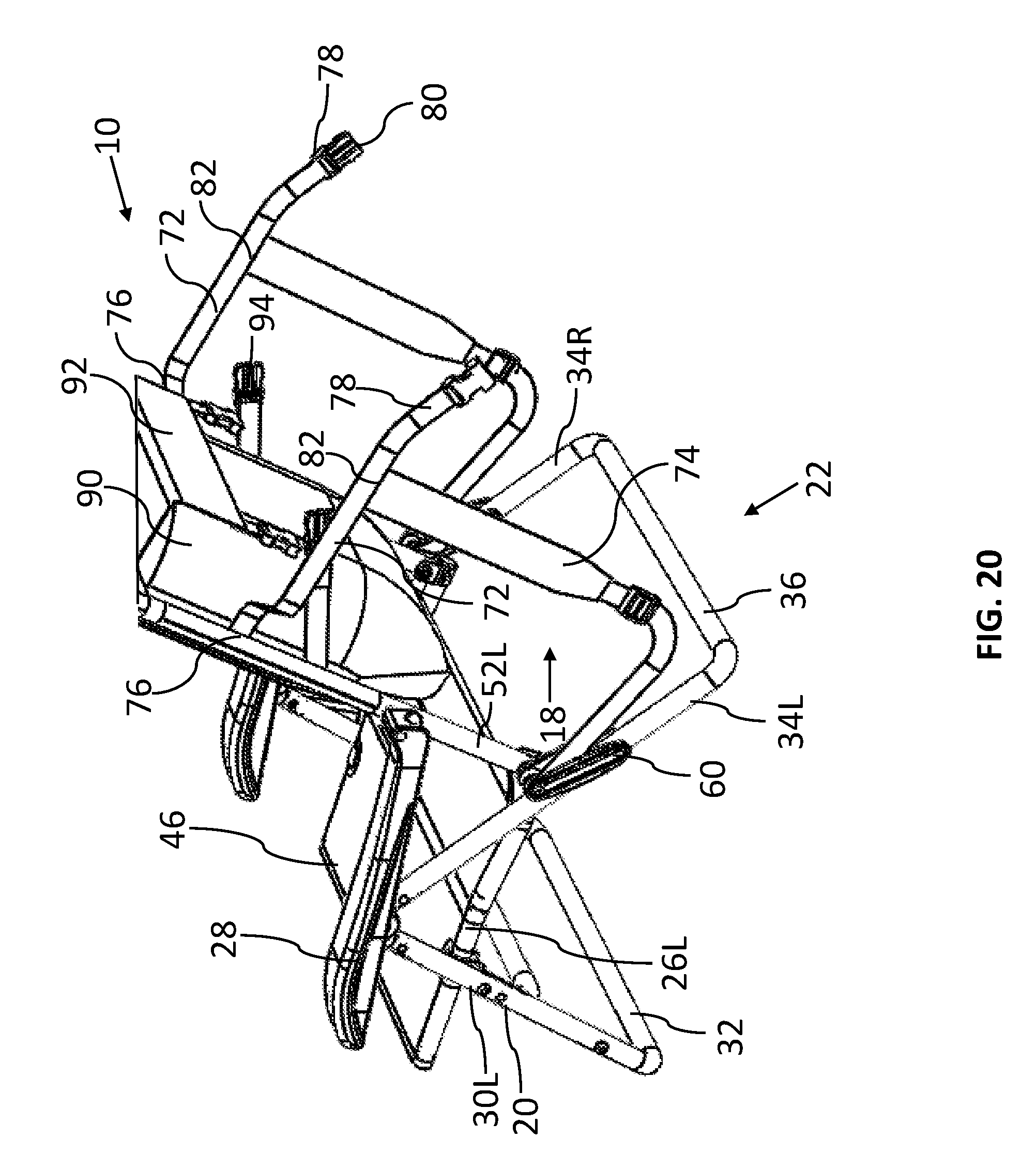
[0046] FIG. 20 illustrates a rear perspective view of a collapsible and portable chair in accordance with a third embodiment of the present invention in a set-up condition.
[0047] FIG. 21 illustrates a side planar view of the chair of FIG. 20.
[0048] FIG. 22 illustrates a front planar view of the chair of FIG. 20 in a folded condition.
[0049] FIG. 23 also illustrates a front planar view of the chair of FIG. 20 in a folded condition.
[0050] FIG. 24 illustrates a side planar view of the chair of FIG. 20 in a folded condition.
DETAILED DESCRIPTION OF EMBODIMENTS OF THE INVENTION
[0051] In the drawings and in the description that follows, the present invention is illustrated and described with reference to embodiments of a collapsible and portable reclining chair embodying the invention.
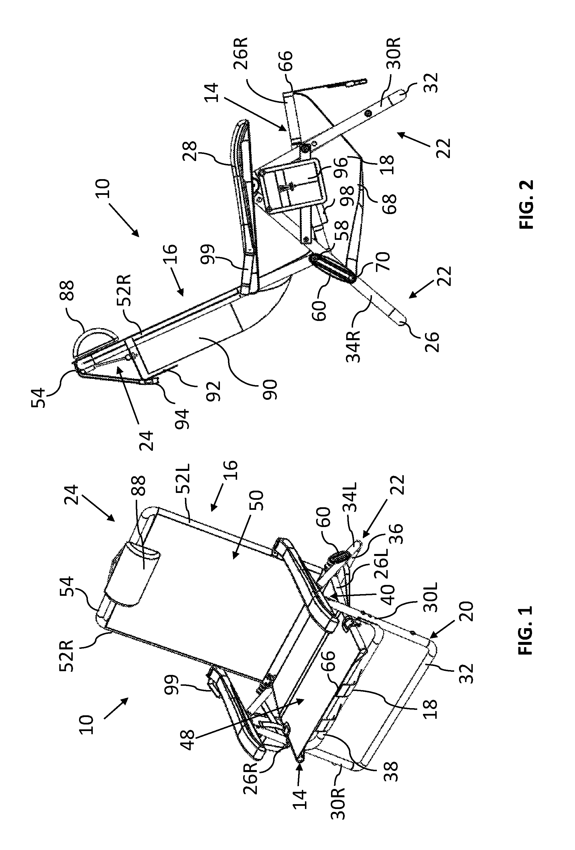
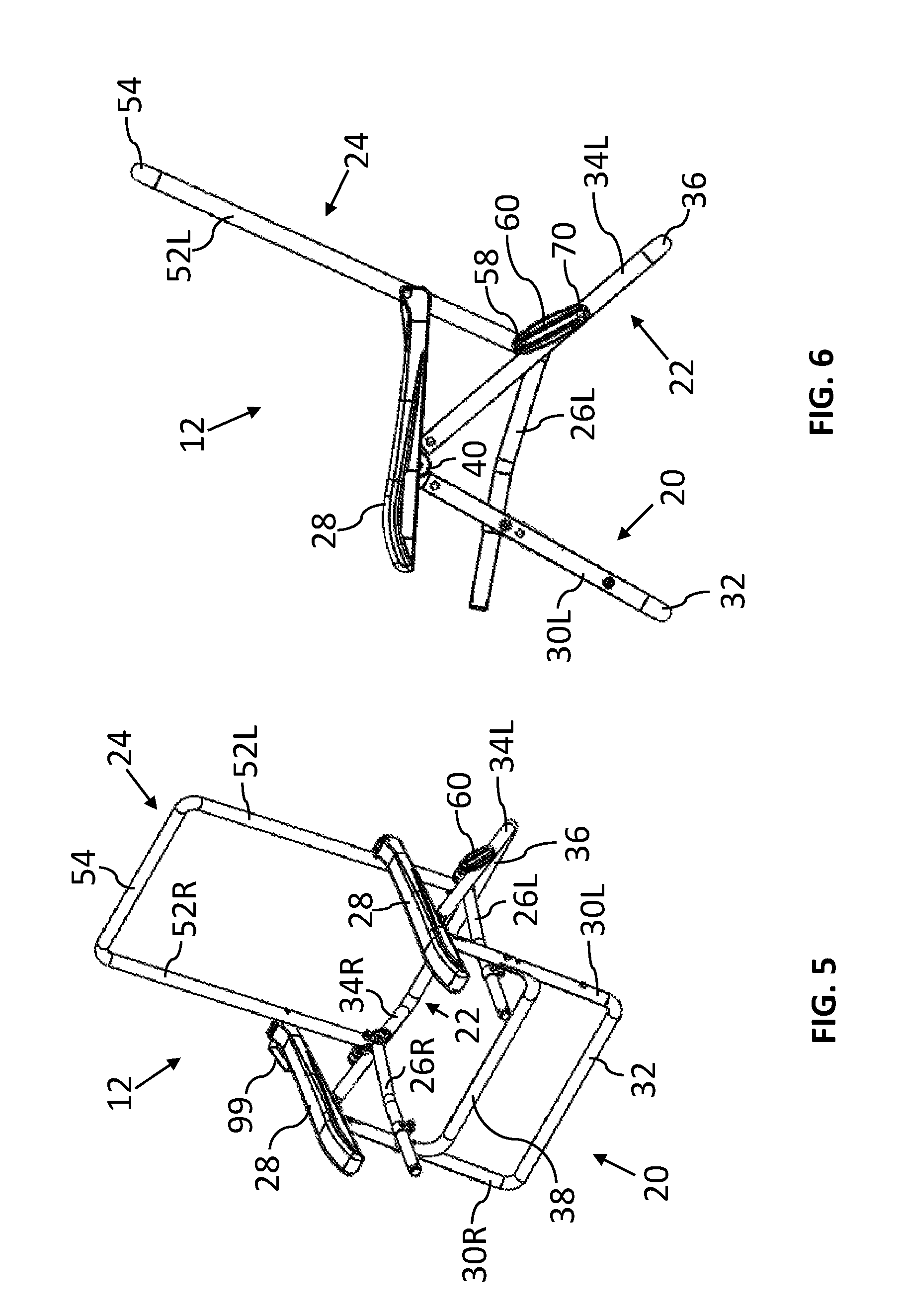
[0052] Referring to FIGS. 1-9, a first embodiment of a collapsible and portable chair is illustrated and indicated generally as reference numeral 10. The illustrated chair 10 essentially comprises a beach or lawn chair having an articulated foldable frame, indicated generally as reference numeral 12, and a flexible material mounted on the frame 12 and defining a chair seat 14 and a chair backrest 16 for receiving a seated user. In FIGS. 1-4, the chair 10 is shown in its set-up condition, wherein the chair 10 is adapted to rest on a generally horizontally-oriented supporting surface for accommodating a seated, or even reclined, chair occupant (not shown). In accordance with the present invention, when the chair 10 is not in use, it may be folded or collapsed for transportation and/or storage, as generally illustrated in FIG. 9, and more particularly, transported like a backpack using shoulder straps 18 attached to the chair frame 12.
[0053] Considering now the chair frame 12 in further detail, as shown in FIGS. 5-8 in its set-up condition, the frame 12 generally comprises a plurality of axially elongated structural members preferably fabricated from durable lightweight tubular metal or polymeric material. In preferred embodiments, the frame members can be aluminum tubing or circular or non-circular cross-section, such as extruded oval or elliptical tubing. According to embodiments of the present invention, in the set-up configuration of the chair 10, the structural frame members of the chair frame 12 are pivotally interconnected by a plurality of pivots or joints that define mutually parallel axes about which the chair frame 12 can be folded in a single motion from the set-up configuration to a flattened or collapsed configuration, as shown in FIG. 9.
[0054] The frame 12 of the general chair 10 in accordance with the present invention comprises a front leg assembly 20, a rear leg assembly 22, a backrest frame assembly 24, laterally spaced apart left and right seat frame members 26, and armrests 28. The front leg assembly 22 comprises left and right front leg members 30L and 30R connected by a lateral cross-connector 32 so that the front leg assembly 20, as illustrated, generally takes the form of a U-shaped part, though it can also have other non-U-shaped forms without departing from the spirit and principles of the present invention. Similarly, the rear leg assembly 22 comprises left and right rear leg members 34L and 34R connected by a lateral cross-connector 36 so that the rear leg assembly 22, as illustrated, generally takes the form of a U-shaped part, though it too can also have other non-U-shaped forms without departing from the spirit and principles of the present invention.
[0055] In embodiments of the present invention, the front leg assembly 20 can be strengthened and reinforced using an additional cross-support member 38 that laterally extends between the left and right front leg members 30L and 30R to add support at the front end of the chair 10 in its set-up condition and when the chair frame 12 is taking the load of a seated user. Such a cross-support member 38 is located well below the seat frame members 26L and 26R so that it does not interfere with the flexibility of a seating panel defining the seat 14--that is, the seating panel can flex below the level of the seat frame members 26L and 26R when a user is seated on the set-up chair 10, and the chair 10 can be easily folded between a set-up and a folded condition, providing a marked improvement over prior art chair frames. As illustrated, the cross-support member 38 is vertically upwardly spaced from the cross-connector 32 of the front leg assembly 20. Additionally, the cross-support member 38 is vertically downwardly spaced from the seat frame members 26L and 26R so as not to interfere with the fabric seating panel, as noted.
[0056] Depending on the shape, size, and specifically, the height of the chair frame 12, a similar cross-support member can be provided on the rear leg assembly 22 as well without departing from the spirit and principles of the present invention.
[0057] The chair frame 12 essentially has a pair of side assemblies of substantially identical and mirrored construction, disposed in laterally spaced apart and generally parallel relation to each other when the chair 10 is in its set-up condition. Such side assemblies are disposed within longitudinally extending generally parallel vertical planes with the afore-mentioned members connected each to another for pivotal movement relative to each other about transversely extending parallel pivotal axes extending normal to the longitudinal axes of the side assembly members. For example, as illustrated in FIG. 6, the front leg member 30L and 30R on each side has an upward and slightly rearward incline to the vertical when the chair 10 is in its set-up condition. These front leg members 30L and 30R are pivotally connected at their upper ends to respective rear leg members 34L and 34R on each side of the chair frame 12, preferably by a hinge fitting 40, which maintains the front and rear leg members within a common horizontally extending vertically disposed axial plane for pivotal movement relative to each other. As a result, the rear leg member 34L and 34R on each side has an upward and forward incline to connect with the respective front leg member 30L and 30R.
[0058] As noted, the front leg assembly 20 and the rear leg assembly 22 are pivotally connected to each other at the top ends of the respective left and right leg members. An armrest 28 sits atop each of the pivotal hinge fittings 40, which may be received within respective adjustment brackets or channels 42 on the underside of the armrests 28, as illustrated in FIGS. 10A and 10B, permitting adjustment of the armrests 28 relative to the pivotal leg connection. The rear end of each armrest 28 is pivotally connected to a side of the backrest frame assembly 24, whereby movement of the armrests 28 back and forth can adjust the reclined position of the backrest 16. For example, the adjustment bracket or channel 42 may include either a grooved opening or recessed guides 44 formed therein with a scalloped shape or angled stops corresponding to various armrest positions relative to the hinge fitting 40, each associated with a different reclined position of the backrest 16. The armrest 28 can be adjusted to one of said positions by lifting it out of engagement with the hinge fitting 40, sliding it to a desired location, and pressing it back down to lock it in place by re-engaging the grooved opening or recessed guide 44 at one of the stops.
[0059] Referring again to FIGS. 5 and 7, the left and right seat frame members 26L and 26R are generally parallel to one another and laterally spaced apart defining a space therebetween. Such members 26L and 26R are independent of one another and unconnected, meaning that there is no structural member, such as a cross-connector or other part of the chair frame 12 connecting the seat frame members 26L and 26R together. In use, a fabric seating panel 48 is stretched between the seat frame members 26L and 26R to receive a seated user. As illustrated and discussed, there are no cross-connectors on the seat frame, and as a result, nothing to interfere with the flex or give of the fabric seating panel 48 when a user is sitting on the set-up chair 10. Moreover, by not using any type of cross-connector or laterally extending frame member at the level of the seat frame 14, there is nothing to press against the user's legs when seated in the chair 10, as is common with prior art designs on the market, such as described in United States Reissue Patent No. RE39,022, which uses a standard and uncomfortable U-shaped seat frame.
[0060] The backrest frame assembly 24 comprises laterally spaced apart left and right backrest frame members 52L and 52R connected at upper ends thereof by a cross-connector 54 so that the backrest frame assembly 24 generally takes the form of a U-shaped part, though it can also have other non-U-shaped forms without departing from the spirit and principles of the present invention. In use, a fabric backrest panel 50 is stretched between the left and right backrest frame members 52L and 52R so that a seated user can lean back on the backrest of the chair 10 in its set-up condition.
[0061] Referring to FIGS. 5-8, the front leg members are pivotally connected on the lateral outer sides of each respective seat frame member 26L and 26R at a location intermediate the top and bottom of each front leg member 22L and 22R. The lower end of the backrest frame member 52L and 52R of each side assembly is pivotally connected in upwardly offset relation to the rear end portion of a respective seat frame member 26L and 26R by a U-shaped upwardly open pivot fitting 56 mounted in fixed position on and at the seat frame member 26L, 26R and via a pivot pin 58 extending through the fitting 56 and the backrest frame member 52L, 52R. As illustrated more clearly in FIG. 8, the pivot pin 58 also pivotally connects the backrest frame member 52L or 52R to an upper end of an over-the-center linkage 60 mounted in side-by-side relation to the pivot fitting 56. The lower end of the linkage 60 straddles the rear portion of the rear leg member 34L or 34R and is pivotally connected to the rear leg member 34L or 34R by another axially transverse pivot pin 62. Thus, the pivotally connected backrest frame assembly 24 and seat frame members 26L and 26R are connected and supported as an assembled unit on the rear leg assembly 22 to pivot as a unit and on and relative to the rear leg assembly 22.
[0062] It is noted that lateral sides of the backrest frame assembly 24 and the seat frame members 26L and 26R are supported to pivot relative to each other within a common plane parallel to the pivotal plane where the upper ends of the front leg assembly 20 and rear leg assembly 22 are connected so as to facilitate simultaneous articulated movement of the chair frame members that enables relatively rapid movement of the chair 10 between its set-up and folded conditions.
[0063] In general, the chair 10 includes at least one fabric panel 46 extending between the laterally spaced frame members to define at least a seating panel 48 and a backrest panel 50 for receiving a seated user in the set-up condition of the chair 10. The fabric panel 46 can be a one-piece panel, defining both the seat and backrest portions of the chair 10, as illustrated in the embodiments of FIGS. 12 and 20. Alternatively, separate panels can be provided for each of the seat 14 and the backrest 16, as illustrated in FIG. 1. Preferably, the fabric material is stretched taut across the frame 12, but is sufficiently flexible to provide ample give, optimally for the seated user's comfort during use of the chair 10. Alternate materials other than fabric panels can be used to define the seat 14 and backrest 16 of the chair 10 in accordance with the present invention, including but not limited to rigid panels, a slatted seat and/or backrest, plastic webbing, mesh, aluminum sheeting, wood, or the like.
[0064] An alternate frame design is illustrated in FIGS. 13-19. In the drawings, like reference numerals refer to like features of chairs in accordance with the present invention. Accordingly, although certain descriptions may refer only to certain figures and reference numerals, it should be understood that such descriptions might be equally applicable to like reference numerals in other figures.
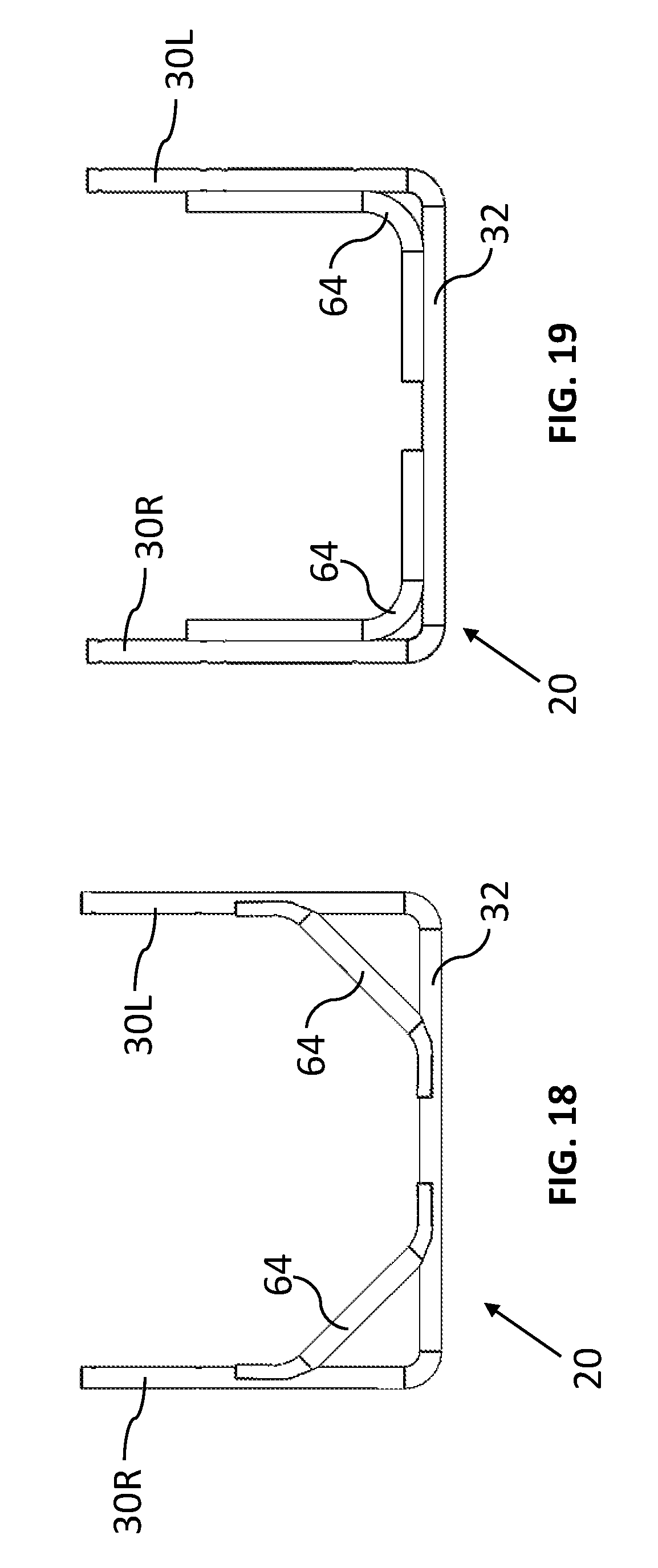
[0065] As shown in FIGS. 16 and 18, the front leg assembly 20 can be strengthened and reinforced using truss braces 64 that add support at the front end of the chair 10 in its set-up condition and when the chair frame 12 is taking the load of a seated user. Variations of such truss braces 64 are illustrated in the FIGS. 18 and 19. In one embodiment shown in FIG. 18, an angular truss brace 64 is provided on each side of the front leg assembly 20. In an alternate embodiment, shown in FIG. 19, separate curved braces 64 can be provided on each side of the front leg assembly 20 that are concentrically aligned with the shape of the front leg assembly 20--for example, following the contour of the side leg members 30L and 30R and the cross-connector 32 to add stability to the set-up chair 10. In further embodiments, a single truss brace 64 can extend the lateral length of the front leg assembly 20 and simply be nested inside the cross-connector 32 to strengthen the front leg assembly 20. Depending on the shape, size, and specifically, the height of the chair frame 12, similar truss braces can be provided on the rear leg assembly 22 as well without departing from the spirit and principles of the present invention.
[0066] As illustrated, the truss braces 64 are located well below seat frame members 26L and 26R assembly so that they do not interfere with the flexibility of the fabric seating panel 48 or affect any part of the seat 14 during use, set-up, or collapsing of the chair 10--that is, the fabric seating panel 48 can flex below the level of the seating frame members 26L and 26R when a user is seated on the set-up chair 10, and the chair 10 can be folded between its set-up and folded conditions, providing a marked improvement over prior art chair frames. As illustrated, the truss braces 64 are vertically downwardly spaced from the seat frame members 26L and 26R so as not to interfere with the fabric seating panel 48, as noted.
[0067] The tendency for a beach chair of the design shown herein, when receiving a seated user or other weight on the seating panel, is to buckle inwardly under the weight. The amount of buckling varies with varying weights of seated users. Moreover, the stress on the chair frame 12 also varies with movement and shifting by the seated user. To counter the buckling stress and forces imparted by the seated user, the chair frame 12 of the present invention is reinforced by either the cross-support member 38 or the truss braces 64, in accordance with the present invention as described herein. However, as noted herein, such reinforcing structural members are specifically located on the chair frame 12 so that they do not interfere with the use and comfort of the chair 10. Additionally, the material used for the leg assemblies 20 and 22 can be selected to retain optimal shape and structure of the chair frame 12. In this regard, extra structural support is not needed on the seat 14 itself (e.g., in the form of a cross-connector forming a U-shaped frame as is common in the prior art), so that the separate and laterally-spaced seat frame members 26L and 26R of the present invention can adequately define the seat 14 and permit the fabric seating panel 48 to flex and give without requiring any obtrusive structure under the seated user's legs.
[0068] The present invention can also be used in with a bi-fold chair design, as generally illustrated in FIG. 11, whereby the chair frame 112, after being folded to a flattened condition, can be folded upon itself to an even smaller footprint for easy transportation and/or storage, such as described in co-pending U.S. patent application Ser. No. 14/991,054, filed Jan. 8, 2016, entitled "Bi-Fold Furniture," which shares a common inventor and assignee with the present application and which is incorporated herein by reference.
[0069] In a bi-fold version of the chair frame 112, central pivot joints, generally designated herein by reference numeral 113, are provided on all the lateral members, such as the cross-connectors 132, 136 and 154 for the front leg assembly 120, the rear leg assembly 122, the backrest assembly 124, and the cross-support member 138 (if used), so that the chair frame 112, after being collapsed from its set-up condition, can be further folded to a more compact condition (second folded condition) for transport and storage. The use of truss braces 64 in accordance with embodiments of the present invention that do not connect to each other obviates the need for additional joints in the truss braces of such a design.
[0070] Embodiments of the present invention further include one or more straps 18 to facilitate carrying the collapsed and folded chair 10. The straps 18 can be secured to the chair 10 or chair frame 12 for transport using known attachment means, including but not limited to stitches, rivets, bolts, screws, buckles, clasps, and the like.
[0071] As shown in FIGS. 1 and 3, the chair 10 is provided with two shoulder straps 18 whereby the folded chair 10 can be worn by the user like a backpack, freeing up the user's hands for carrying other objects. In such embodiments, one end 66 of a strap 18 is attached to the seat frame members 26L and 26R or the fabric seating panel 48 and the other end 68 is attached to or near the rear leg members 34L and 34R on each side of the chair frame 12. More particularly, as illustrated in FIGS. 2 and 3, a first end 66 of each strap 18 is sewn to the underside of the fabric seating panel 48. The second end 68 of each strap 18 is held in place on the rear leg assembly 22 by a pivot pin 70 connecting the over-the-center linkage 60 to the rear leg member 34L or 34R. When the chair 10 is in its set-up condition, the straps 18 can hang down underneath the set-up chair 10, as shown in FIG. 2. When the chair 10 is collapsed, the straps 18 are positioned on one side of the folded assembly so that the user can easily slip her arms through the straps 18 to wear the folded chair 10 on her back like a backpack.
[0072] In alternate embodiments of the present invention, as illustrated in FIGS. 12-17 and 20-24, each strap 18 can comprise two portions--a generally horizontal belt portion 72 and a generally vertical strap portion 74. The generally horizontal belt portion 72 (when attached for backpack transport) has a first end 76 connected to the back side of the fabric backrest panel 50 or directly to the backrest frame member 52L or 52R, and an opposing second end 78 with a connection means 80 adapted for connecting the left horizontal belt portion 72 with the right horizontal belt portion 72. Preferably, the connection means 80 comprise a buckle and clasp pairing for easy engagement and disengagement. Each generally vertical strap portion 74 is attached at a first end 82 to a respective horizontal belt portion 72 and hangs down therefrom to define backpack straps when the chair 10 is in its folded condition. The second end 84 of the vertical strap portion 74 is connected to the chair frame 12. When the user carries the chair 10 like a backpack, the user's arms are inserted through the vertical strap portions 74, which sit on the user's shoulders. The horizontal belt portions 72 are positioned behind the user's shoulders and back. The vertical strap portions 74 can also include padding for comfort. Additionally, adjustment clasps 86 can be provided to adjust the length of the vertical strap portions 74 to accommodate users of different sizes.
[0073] Referring to FIG. 21, the second end 84 of each vertical strap 74 is attached to the front leg frame assembly 20, preferably towards the lower end of the U-shaped front leg just above the horizontal. As noted, the first end 82 of the vertical strap portion 74 is attached to the horizontal belt portion 72, which in turn is sewn to the back side of the fabric backrest panel 50 or attached to the backrest frame member 52L or 52R, preferably about mid-way up the backrest 16, as better illustrated in FIGS. 20 and 21. The vertical strap portion 74 can be stitched to the horizontal belt portion 72, as shown, or alternatively may be horizontally adjustable to accommodate different users.
[0074] Referring to FIG. 12, an alternate strap arrangement is illustrated. As shown in FIGS. 12-14, for example, the second end 84 of each vertical strap portion 74 is attached to the rear leg frame assembly 22, preferably to the over-the-center linkage 60 or alternatively, wrapped around the rear leg member 34L or 34R or the backrest frame member 52L or 52R in the vicinity of the over-the-center linkage 60. The first end 82 of each vertical strap portion 74 is attached to the respective horizontal belt portion 72, which, in turn, sewn to the back side of the fabric backrest panel 50 or attached to the backrest frame member 52L or 52R.
[0075] In each of these embodiments of the carrying straps 18, when the chair 10 is in its set-up condition, the straps 18 can hang off the backrest 16. Advantageously, in the set-up condition of the chair 10, the straps 18 fall adjacent to the sides of the chair 10 and are generally suspended off the ground so they are less apt to get dirty or muddy than is customary with prior art designs. When the chair 10 is collapsed, the straps 18 can be pulled around the sides of the folded chair 10 and connected to each other using the buckle and clasp arrangement 80 to defined backpack straps whereby the user can carry the folded chair 10 on his or her back like a backpack, freeing up the user's hands for carrying other objects. The location and arrangement of the straps 18 and the buckle and clasp arrangement 80 to connect them together also acts to keep the chair 10 in its folded condition during transport, even if the straps 18 are not being used as for carrying, by having the straps 18 wrap around the frame 12 from the back-side of the backrest support to the front side of the folded chair 10, as shown in FIGS. 17 and 24.
[0076] The backpack straps 18 described and shown herein can be used with different chair frame designs without departing from the spirit and principles of the present invention. For example, the straps 18 of the present invention may be used in a bi-fold chair design, as described above, whereby the chair frame 112, after being folded to a flattened condition, can be folded upon itself to a second folded condition having an even smaller footprint (about half the footprint of the chair in the first folded condition) for easy transportation and/or storage. Such a bi-fold chair design could also use just one carrying strap, whereby the folded chair could be transported like a messenger bag.
[0077] Additional features may be provided with the chair 10 to improve its functionality. For example, referring to FIG. 1, a pillow 88 can be provided at the top of the backrest 16. A storage pouch 90 can be located on the back-side of the backrest 16 for storing items, both when the chair 10 is set-up and when the chair 10 is folded and carried on the user's back using the provided backpack straps 18, as shown in FIGS. 4 (set-up condition) and 9 (folded condition). When the folded chair 10 is carried like a backpack, the pouch 90 extends off the back of the chair 10, essentially creating a backpack. A flap 92 can be provided to enclose the pouch 90 to secure items within the pouch 90. Additionally, the flap 92 can be kept closed by known fastening means such as the buckles 94 illustrated, or by hook-and-loop fasteners, snaps, buttons, zippers and the like.
[0078] Additional features that can be provided with the chair designs of the present invention, include a cup holder 96 hanging from one or both of the armrests 28; an additional storage pouch 98 hanging from one or both of the armrests 28; and a carrying handle 99 provided on one or both of the armrests 28 providing another means for transporting the folded chair 10.
[0079] The foregoing description of embodiments of the invention has been presented for the purpose of illustration and description. It is not intended to be exhaustive or to limit the invention to the form disclosed. Obvious modifications and variations are possible in light of the above disclosure. The embodiments described were chosen to best illustrate the principles of the invention and practical applications thereof to enable one of ordinary skill in the art to utilize the invention in various embodiments and with various modifications as suited to the particular use contemplated.
* * * * *
D00000
D00001
D00002
D00003
D00004
D00005
D00006
D00007
D00008
D00009
D00010
D00011
D00012

D00013

D00014

D00015

XML
uspto.report is an independent third-party trademark research tool that is not affiliated, endorsed, or sponsored by the United States Patent and Trademark Office (USPTO) or any other governmental organization. The information provided by uspto.report is based on publicly available data at the time of writing and is intended for informational purposes only.
While we strive to provide accurate and up-to-date information, we do not guarantee the accuracy, completeness, reliability, or suitability of the information displayed on this site. The use of this site is at your own risk. Any reliance you place on such information is therefore strictly at your own risk.
All official trademark data, including owner information, should be verified by visiting the official USPTO website at www.uspto.gov. This site is not intended to replace professional legal advice and should not be used as a substitute for consulting with a legal professional who is knowledgeable about trademark law.