Protective Glove Having Self-occluding Cuff
Bader; Yves
U.S. patent application number 16/053100 was filed with the patent office on 2019-03-21 for protective glove having self-occluding cuff. The applicant listed for this patent is E I DU PONT DE NEMOURS AND COMPANY. Invention is credited to Yves Bader.
| Application Number | 20190082754 16/053100 |
| Document ID | / |
| Family ID | 63763018 |
| Filed Date | 2019-03-21 |


| United States Patent Application | 20190082754 |
| Kind Code | A1 |
| Bader; Yves | March 21, 2019 |
PROTECTIVE GLOVE HAVING SELF-OCCLUDING CUFF
Abstract
A glove comprising cut-resistant fibers, the glove comprising a glove body and a cuff, the cuff further defining an opening in the glove and having a circumferential inner surface that faces a body when worn, the cuff being further provided with a plurality of magnetic pieces, wherein when the glove is not being worn, the magnetic pieces compress the cuff and close the opening.
| Inventors: | Bader; Yves; (Crozet, FR) | ||||||||||
| Applicant: |
|
||||||||||
|---|---|---|---|---|---|---|---|---|---|---|---|
| Family ID: | 63763018 | ||||||||||
| Appl. No.: | 16/053100 | ||||||||||
| Filed: | August 2, 2018 |
Related U.S. Patent Documents
| Application Number | Filing Date | Patent Number | ||
|---|---|---|---|---|
| 62561324 | Sep 21, 2017 | |||
| Current U.S. Class: | 1/1 |
| Current CPC Class: | A41D 19/0048 20130101; A41F 1/002 20130101; A41F 1/06 20130101; A41D 19/01505 20130101; A41D 19/002 20130101 |
| International Class: | A41D 19/015 20060101 A41D019/015; A41D 19/00 20060101 A41D019/00; A41D 31/00 20060101 A41D031/00; D04B 1/28 20060101 D04B001/28; D04B 21/20 20060101 D04B021/20 |
Claims
1. A glove comprising cut-resistant fibers, the glove comprising a glove body and a cuff, the cuff further defining an opening in the glove and having a circumferential inner surface that faces a body when worn, the cuff being further provided with a plurality of magnetic pieces, wherein when the glove is not being worn, the magnetic pieces compress the cuff and close the opening.
2. The glove of claim 1 wherein the cuff is compressed by the attraction of the magnetic pieces on opposing sides of the cuff.
3. The glove of claim 1 wherein the opening is closed by contact of opposing inner surfaces of the cuff.
4. The glove of claim 1 wherein the magnetic pieces are sewn into the cuff.
5. The glove of claim 1 wherein the magnetic pieces are distributed in a circumferential pocket formed in the cuff.
6. The glove of claim 1 wherein the magnetic pieces are distributed in an elastomeric band that is incorporated into the cuff.
7. The glove of claim 1 wherein the cut-resistant fibers are aramid, polyethylene, glass, or mixtures thereof.
8. The glove of claim 1 wherein the cuff further comprises metal pieces.
9. The glove of claim 8 wherein the magnetic pieces and metal pieces are on opposing sides of the cuff.
Description
BACKGROUND OF THE INVENTION
Field of the Invention
[0001] This invention relates to improvements in gloves comprising cut-resistance fibers and filaments.
Description of Related Art
[0002] Magnets have been used to replace buttons on apparel, such as disclosed for example in US Patent Publication 2009/0178245 to Albert; U.S. Pat. No. 9,210,953 to Horton; and U.S. Pat. No. 2,319, 292 to Boggs. Such applications typically use the magnets to hold together overlapping edges of the garment during the wearing of the garment.
[0003] Gloves made with cut resistant fibers are used in industry to protect workers' hands from cuts and abrasions from such things as metallic parts. For example, autoworkers will wear protective gloves to protect their hands when handling metallic car hoods. Such gloves can become dirty with use and are washed. It has been found that in the washing cycles, bits of metal collected on the outer surface of the glove during use can dislodge in the wash; and further, can migrate inside the glove. A worker subsequently donning the washed glove can be injured by this metal residue that is now present inside the glove.
[0004] What is needed is a method of restricting foreign matter from entering the interior of a glove when the glove is not worn, and particularly when the glove is washed.
BRIEF SUMMARY OF THE INVENTION
[0005] This invention concerns a glove comprising cut-resistant fibers, the glove comprising a glove body and a cuff, the cuff further defining an opening in the glove and having a circumferential inner surface that faces a body when worn, the cuff being further provided with a plurality of magnetic pieces, wherein when the glove is not being worn, the magnetic pieces compress the cuff and close the opening.
BRIEF DESCRIPTION OF THE DRAWINGS
[0006] FIG. 1 is an illustration of a glove having a glove body, a cuff, and magnetic pieces distributed in the cuff.
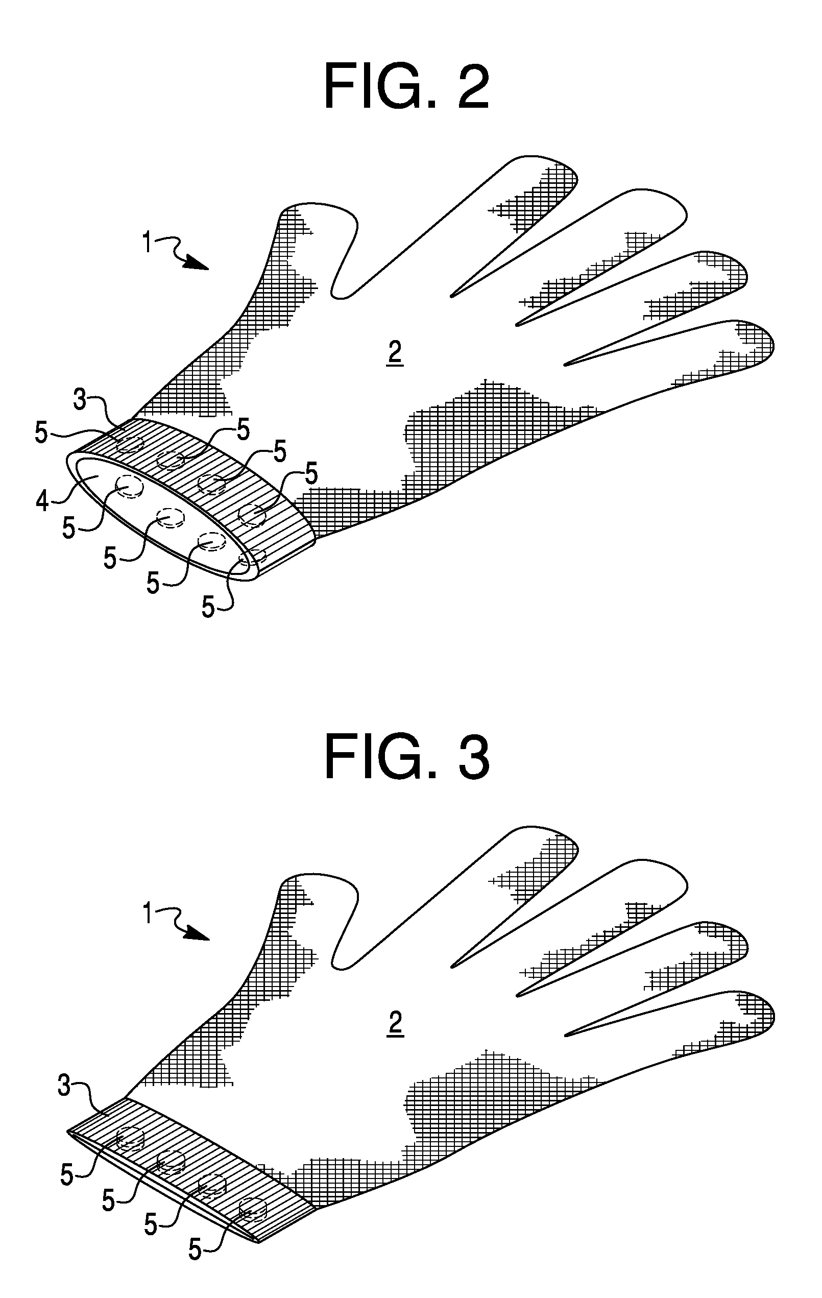
[0007] FIG. 2 is a perspective view of the glove having magnetic pieces distributed in the cuff and the opening for the insertion of a hand.
[0008] FIG. 3 is a perspective view of the glove having magnetic pieces distributed in the cuff wherein the magnetic pieces compress the cuff and close the opening.
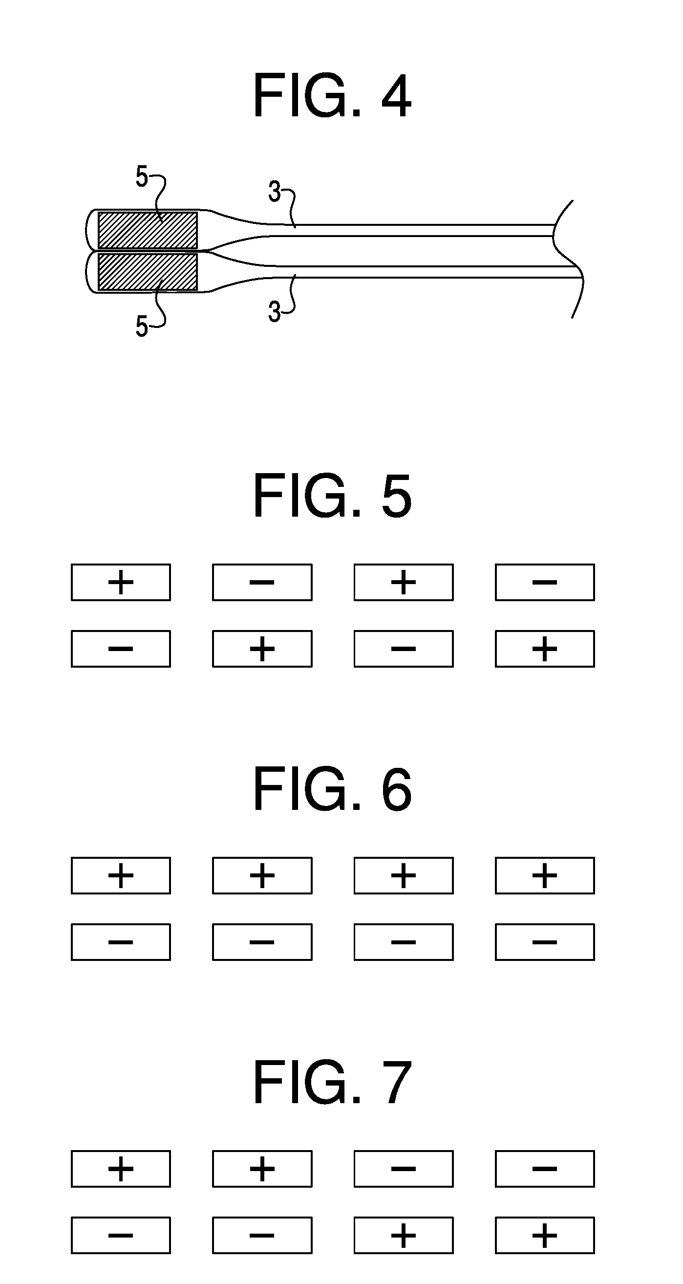
[0009] FIG. 4 is a detail of the compressed cuff provided by the attraction of the magnetic pieces.
[0010] FIGS. 5, 6, & 7 are illustrations of possible polarities of the magnetic pieces distributed in the cuff of the glove.
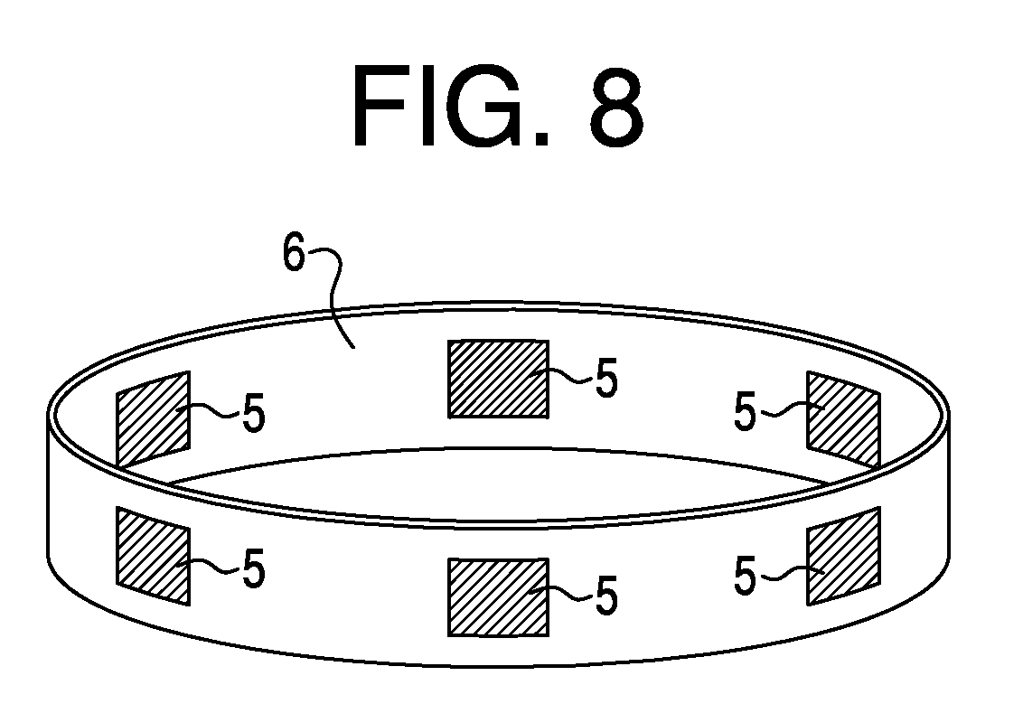
[0011] FIG. 8 illustration of a continuous elastomeric band having distributed magnetic pieces for insertion into a glove cuff.
DETAILED DESCRIPTION OF THE INVENTION
[0012] FIGS. 1 & 2 illustrate a glove 1 comprising a glove body 2 and a cuff 3, the cuff further defining an opening 4 in the glove for the insertion of a hand, the cuff having a circumferential inner surface that faces the body when worn. The cuff is further provided with a plurality of magnetic pieces 5. As shown in perspective view FIG. 3 and detail view FIG. 4, when the glove is not being worn, the magnetic pieces 5 compress the cuff 3 and bring opposing sides of the circumferential inner surface of the cuff together to close the opening.
[0013] The glove body comprises a fabric containing cut-resistant fibers. The fabric may be a knit fabric or a woven fabric or any other fabric but is preferably is knit fabric. The cuff also preferably contains cut-resistant fibers. In many instances, the cuff fabric is also the same general type of fabric as the glove body. The glove body can have a top side covering the back of the hand, and a palm side covering the palm of the hand, and is connected to the cuff. Likewise, the cuff can have a top side covering the back of the wrist (that is, next to the back of the hand) and a bottom side covering the opposing side of the wrist (that is, next to the palm). The cuff is connected to the glove body, and in typical preferred construction the glove and cuff are knit directly from yarns using advanced knitting machines. The cuff also preferably incorporates some elastomeric material, such as an elastomeric yarn that has stretch and recovery.
[0014] One preferred elastomeric yarn utilizes spandex fiber; however, any fiber generally having stretch and recovery can be used. As used herein, "spandex" has its usual definition, that is, a manufactured fiber in which the fiber-forming substance is a long chain synthetic polymer composed of at least 85% by weight of a segmented polyurethane. Among the segmented polyurethanes of the spandex type are those described in, for example, U.S. Pat. Nos. 2,929,801; 2,929,802; 2,929,803; 2,929,804; 2,953,839; 2,957,852; 2,962,470; 2,999,839; and 3,009,901.
[0015] In some processes for making spandex elastomeric filaments, coalescing jets are used to consolidate the spandex filaments immediately after extrusion. It is also well known that dry-spun spandex filaments are tacky immediately after extrusion. The combination of bringing a group of such tacky filaments together and using a coalescing jet will produce a coalesced multifilament yarn, which is then typically coated with a silicone or other finish before winding to prevent sticking on the package. Such a coalesced grouping of filaments, which is actually a number of tiny individual filaments adhering to one another along their length, is superior in many respects to a single filament of spandex of the same linear density.
[0016] The elastomeric yarn used is preferably a continuous filament and can be present in the elastomeric yarn in the form of one or more individual filaments or one or more coalesced grouping of filaments. However, it is preferred to use only one coalesced grouping of filaments in the preferred elastomeric yarn. Whether present as one or more individual filaments or one or more coalesced groupings of filaments, the overall linear density of the elastomer filament(s) in the relaxed state is generally between 17 and 560 dtex (15 and 500 denier) with the preferred linear density range being 44 to 220 dtex (40 to 200 denier). In some embodiments, a covered elastomeric yarn can be used; that is, a yarn having a yarn core comprising at least one elastomeric or spandex yarn, and one or more 20 to 300 denier (22 to 340 dtex) wrapping yarn(s) helically wrapped around the elastomeric or spandex yarn core, the wrapping yarn(s) preferably comprising aliphatic polyamide, polyester, natural fibers, cellulosic fibers, or mixtures thereof.
[0017] In addition to, or instead of the use of elastomeric yarn, the cuff can incorporate a continuous or discontinuous elastomeric band. By discontinuous elastomeric band, it is meant the cuff can contain one or more pieces or segments of elastomeric band material. The use of the elastomeric material allows the cuff of the glove to gather about or grip the wrist and better keep the glove on the hand during wearing, but can also stretch to allow the hand to enter and exit the glove through the opening 4 in the glove.
[0018] The cuff is further provided with a plurality of magnetic pieces. By magnetic, is meant a material that has its component atoms so ordered that the material exhibits the properties of magnetism, such as attracting other iron-containing objects or aligning itself in an external magnetic field. Typically, such magnetic pieces are iron or a metal alloy, and are known as permanent magnets.
[0019] The magnetic pieces preferably have a minor thickness dimension and greater major dimension(s) that is typically either an effective length and width, or an effective radius. The major dimension(s) of the pieces can have a multitude of shapes, with useful shapes including round-shaped pieces, rectangular-shaped pieces, or square-shaped pieces. The size of the pieces should be compatible with the size of the cuff into which they are being incorporated. Typically, the magnetic pieces have major dimensions (length.times.width or an effective radius) resulting in a major dimensional area of 4.5 mm.sup.2 to 75 mm.sup.2, with pieces having a major dimensional area of 12 mm.sup.2 to 24 mm.sup.2 being preferred. The plurality of magnetic pieces is distributed in the cuff in a manner that allows for stretching of the cuff during donning of the glove, while the pieces are also preferably positioned in the cuff such that individual magnetic pieces can attract another piece on the opposing side of the cuff to compress and close the cuff. In some embodiments, the magnetic pieces are sewn into the cuff. This can be done by folding the end of the cuff onto itself to form a circumferential pocket, followed by inserting and distributing the magnetic pieces, and then stitching to close the pocket. Preferably additional stitches can be used to stabilize the desired circumferential location of the magnetic pieces in the cuff.
[0020] In one embodiment, the cuff can incorporate a continuous elastomeric band 6 having magnetic pieces 5, as shown in FIG. 8. In another embodiment, the cuff can utilize a discontinuous elastomeric band, as described herein before, having magnetic pieces. For example, two or more elastomeric band pieces having magnetic pieces can be incorporated into the cuff without forming a continuous circumferential elastomeric band around the wrist. The elastomeric band material can preferably be used in addition to elastomeric yarns in the cuff, or alternatively as the sole elastomeric material in the cuff.
[0021] As with the magnetic pieces, preferably the elastomeric band or sections of band are sewn into the cuff in a pocket preferably formed by stitching; the pocket is then further closed with additional stitching. When a plurality of elastomeric band sections is used, preferably additional stitches are used to position and stabilize the desired circumferential location of the sections in the cuff.
[0022] The elastomeric band can be made from an elastomeric polymer, and silicone and polyurethane polymers are two such polymers that are useful; with polyurethane polymers being preferred materials. The magnetic pieces can be incorporated into the elastomeric band by curing the elastomeric material in a band mold having the pieces positioned at the selected intervals around the mold.
[0023] Other pieces, such as a plurality of metal pieces that are not magnets but are drawn to or attracted to the magnetic pieces, can be used in the cuff in conjunction with the plurality of magnetic pieces. These pieces can have the same general shape and size as the magnetic pieces. In some embodiments, one side of the cuff can have magnetic pieces while the other has metal pieces that are attracted by the magnetic pieces; the pieces positioned in the cuff such that the magnetic pieces can attract the metal pieces on the opposing side of the cuff to compress and close the cuff.
[0024] FIG. 3 is a perspective view and FIG. 4 is a detail view of the glove wherein the magnetic pieces 5 have closed, that is occluded, the opening in the glove such that debris cannot enter. FIGS. 5, 6, & 7 are simplified detailed views of several potential arrangements of the polarity of the four sets of magnetic pieces 5 shown in FIG. 3 that create a magnetic field between the opposing sides of the cuff; the upper set of magnetic pieces being disposed in the top side of the cuff, and lower set of magnetic pieces being disposed in the bottom side of the cuff. As shown, the positive and negative polarity can vary between the sets of magnetic pieces or each set can have a different polarity. Also, one set can simply be a number of metallic pieces that are attracted by magnetic pieces. While four sets of magnetic pieces are shown in these figures, any number of magnetic pieces (or magnetic and metal pieces) can be used as long as the cuff functions as desired. In some preferred embodiments, preferably there are at least 3 sets of magnetic pieces, or magnetic and metal pieces, in the cuff.
[0025] When the glove is not being worn, it is self-occluding. By self-occluding, it is meant the magnetic attraction generated by the magnetic pieces attracts and compresses together the opposing sides of the circumferential inner surface of the cuff and close the opening 4, as shown in FIGS. 2 & 3, without substantial additional force, other than to the lay the unworn glove on another surface, such as a pile of laundry or a flat table. The magnetic attraction generated by the magnetic pieces secures the two sides of the cuff together to prevent passage of metal fragments into the interior of the glove when the glove is washed. In other words, when the glove is not worn, the magnet pieces compress the cuff to occlude the opening formed by the cuff by contact of opposing sides of the circumferential inner surface of the cuff, preventing debris from entering the glove. In one embodiment, the top side (back of hand/wrist) of the cuff is compressed to the bottom side (the palm side of the hand/wrist of the glove) when the glove is not worn.
[0026] Further, the opposing sides of the circumferential inner surface of the cuff can be separated without undue force to don the glove. Generally, the force between the opposing sides of the circumferential inner surface of the cuff should be at least adequate to compress the opposing sides of the cuff together if the glove is removed and placed on a flat surface, and maintain contact of the opposing sides through a wash cycle. In some embodiments, the force required to either compress or separate the opposing sides is about 1 to 7 newtons. In some preferred embodiments, the force required to either compress or separate the opposing sides is about 2 to about 5 newtons. The force required to separate the opposing sides can be determined by attaching one side of the cuff to a stationary object and then pulling the other side with a digital dynamometer, such as a dynamometer available from Pesola.RTM., to determine the force required to separate the opposing sides of the cuff. Herein, the force required to compress the opposing sides of the cuff is considered to be the same as the force required to separate the opposing sides.
[0027] In some embodiments, the cut-resistant fibers are preferably present in the glove in the form of yarns, and the preferred cut-resistant fibers are organic fibers, either in staple or continuous filament form; however, inorganic fibers can also be used. The yarns can be filament yarns, textured yarns, staple yarns, or hybrids of any of these. The fibers preferably have a diameter of 5 to 25 micrometers and a linear density of 0.5 to 7 dtex. When staple fibers are used in the yarns, the staple fibers can have a preferred length of 2 to 20 centimeters, and more preferably 3.5 to 6 centimeters.
[0028] Cut resistant fibers have a Cut Index of at least 0.8 and preferably a Cut Index of 1.2 or greater. The most preferred fibers have a Cut Index of 1.5 or greater. As used herein, the Cut Index is the cut performance of a 475 grams/square meter (14 ounces/square yard) fabric woven or knitted from 100% of the fiber to be tested and has units of either grams force per grams/square meter or centi-Newtons per grams/square meter. To determine the Cut Index, first the Cut Protection Performance (CPP) value is measured, using either a CPPT Cut Device per ASTM F1790-15, or a TDM Cut Device per either ASTM 2992-15 or ISO 13997-1999. The Cut Index is calculated by dividing the CPP value, either in grams or centi-Newtons, by the areal density of the fabric tested in grams per square meter. Table 1 lists some useful fibers and their cut performance. The CPP values listed below are averages of fabric weights that have an areal density of about 475 grams/square meters (14 ounces/square yard). Individual measurements made from a range of fabric weights may have slightly different Cut Index values than the values below.
TABLE-US-00001 TABLE 1 Areal Density CPP CPP Cut Index Cut Index Fiber(s) (g/m.sup.2) (g) (N) (g/g/m.sup.2) cN/g/m.sup.2 PPD-T 475 1050 10.5 2.2 2.2 Cotton 475 425 4.2 0.9 0.9 Blends of 40- 475 550-850 5.5-8.5 1.2-1.8 1.2-1.8 80 wt % Cotton & 20-60 wt % PPD-T Ultra-High MW 475 900 9 1.9 1.9 Polyethylene Polyamide 475 650 6.5 1.4 1.4 (nylon) Polyester 475 650 6.5 1.4 1.4
[0029] In some embodiments, the preferred cut-resistant fibers are para-aramid fibers. By para-aramid fibers is meant fibers made from para-aramid polymers; poly(p-phenylene terephthalamide) (PPD-T) is the preferred para-aramid polymer. By PPD-T is meant the homopolymer resulting from mole-for-mole polymerization of p-phenylene diamine and terephthaloyl chloride and, also, copolymers resulting from incorporation of small amounts of other diamines with the p-phenylene diamine and of small amounts of other diacid chlorides with the terephthaloyl chloride. Other diamines and other diacid chlorides can be used in amounts up to as much as about 10 mole percent of the p-phenylene diamine or the terephthaloyl chloride, or perhaps slightly higher, provided only that the other diamines and diacid chlorides have no reactive groups which interfere with the polymerization reaction. PPD-T, also, means copolymers resulting from incorporation of other aromatic diamines and other aromatic diacid chlorides such as, for example, 2,6-naphthaloyl chloride or chloro- or dichloroterephthaloyl chloride; provided, only that the other aromatic diamines and aromatic diacid chlorides be present in amounts which do not adversely affect the properties of the para-aramid.
[0030] Additives can be used with the para-aramid in the fibers and it has been found that up to as much as 10 percent, by weight, of other polymeric material can be blended with the aramid or that copolymers can be used having as much as 10 percent of other diamine substituted for the diamine of the aramid or as much as 10 percent of other diacid chloride substituted for the diacid chloride of the aramid.
[0031] Para-aramid (p-aramid) fibers are generally spun by extrusion of a solution of the p-aramid through a capillary into a coagulating bath. In the case of poly(p-phenylene terephthalamide), the solvent for the solution is generally concentrated sulfuric acid, the extrusion is generally through an air gap into a cold, aqueous, coagulating bath. Such processes are generally disclosed in U.S. Pat. Nos. 3,063,966; 3,767,756; 3,869,429, & 3,869,430. P-aramid fibers are available commercially as Kevlar.RTM. fibers, which are available from E. I. du Pont de Nemours and Company, and Twaron.RTM. fibers, which are available from Teijin, Ltd.
[0032] Other preferred cut resistant fibers useful in this invention are ultra-high molecular weight or extended chain polyethylene fiber, such as generally prepared as discussed in U.S. Pat. No. 4,457,985. Such fiber is commercially available under the trade names of Dynema.RTM. available from DSM and Spectra.RTM. available from Honeywell.
[0033] One suitable and preferred cut resistant inorganic fiber is glass fiber. The terms glass fiber and fiberglass are used interchangeably herein and generally refer to glass fiber filament yarn. Glass fiber is formed by extruding molten silica-based or other formulation glass into thin strands or filaments with diameters suitable for textile processing. Two types of fiberglass commonly used are referred to as S-glass and E-glass. E-glass has good insulation properties and will maintain its properties up to 1500 degrees F. (800 degrees C.). S-glass has a high tensile strength and is stiffer than E-glass. Suitable glass fiber is available from B&W Fiber Glass, Inc. and a number of other glass fiber manufacturers. In some embodiments, the use of E-glass is preferred in the cut-resistant composite yarn.
[0034] Other preferred cut resistant fibers are aramid fibers based on copoly(p-phenylene/3,4'-diphenyl ether terephthalamide) such as those known as Technora.RTM. available from Teijin, Ltd. Less preferred but still useful at higher weights are fibers made from polybenzoxazoles, anisotropic melt polyester, polyamides; polyesters; and blends of preferred cut resistant fibers with less cut resistant fibers.
Test Methods
[0035] Cut Resistance. The Cut Index is the cut performance of a 475 grams/square meter (14 ounces/square yard) fabric woven or knitted from 100% of the fiber to be tested and has units of either grams force per grams/square meter or centi-Newtons per grams/square meter. To determine the Cut Index, first the Cut Protection Performance (CPP) value is measured, using either a CPPT Cut Device per ASTM F1790-15, or a TDM Cut Device per either ASTM 2992-15 or ISO 13997-1999. The Cut Index is calculated by dividing the CPP value, either in grams or centi-Newtons, by the areal density of the fabric tested in grams per square meter.
[0036] Separation/Compression Force. The force required to separate the opposing sides of the compressed cuff can be determined by attaching one side of the cuff to a stationary object and then pulling the other side with a digital dynamometer, such as a dynamometer available from Pesola.RTM., to separate the opposing sides of the cuff. Herein, the force required to compress the opposing sides of the cuff is considered to be the same as the force required to separate the opposing sides.
EXAMPLE 1
[0037] A cut-resistant glove was made from a 720 dtex (650 denier) cut resistant 100% Kevlar.RTM. para-phenylene terephthalamide (aramid) spun yarn (Style 970 Z), which had a cotton count of 16/2 and a twist of 7.86 twist/inch. The glove was direct knitted on a Shima Seiki 13 gauge knitting machine, model SFG-I L2/L3. The glove was knitted at a speed of 120 rpm on the machine, with a knitting stitch of 30 (according to Shima Seiki scale) to form a size 9 glove according to EN 420, except the cuff, which had a length of 9.5 cm. The cuff was direct knitted into the glove during the same process, with the addition of an elastomeric yarn that was 53% polyamide and 47% elastodiene and had a linear density of 2600 dtex, which was supplied by Adatex Sa Industrial E Comercial.
[0038] Permanent magnets (model ZCE-V12-03-N40) were obtained from Systemmag S.A.S. The magnets were incorporated into the cuff by rolling the cuff to form a hemstitch, inserting the magnets (which were distributed evenly in the cuff), and then sewing the hemstitch closed to encapsulate the magnets in the cuff. The magnet pieces were positioned in the cuff such that they could attract magnet piece on the opposing side of the cuff to close the cuff when the glove was not worn. The force required to open the closed cuff, as measured with a Pesola.RTM. dynamometer, was 3 N.
EXAMPLE 2
[0039] Example 1 is repeated, but rather than use all individual magnets, a combination of magnetic pieces and metal pieces that are attracted by the magnetic pieces are inserted and distributed evenly in the cuff, with a similar result.
EXAMPLES 3 and 4
[0040] For Example 3, Example 1 is repeated, but a continuous elastomeric band having distributed magnetic pieces is inserted into the cuff rather than individual magnets. The elastomeric material in the band is in the form of a polyurethane elastomeric matrix having permanent magnets and is available from System mag S.A.S. Likewise, for Example 4, Example 2 is repeated, using a continuous elastomeric band having both magnetic and metal pieces rather than individual magnetic and metal pieces.
[0041] In both Examples, the magnetic pieces (or magnetic and metal pieces) in the band are positioned in the cuff such that they attract a magnetic piece (or metal piece) on the opposing side of the cuff. Both gloves function with a similar result.
EXAMPLES 5 and 6
[0042] For Examples 5 and 6, the Examples 3 and 4 are repeated, but a discontinuous elastomeric band is used in the cuff. For Example 5, two sections of elastomeric band having distributed magnetic pieces, each having a length that is roughly about 30% of the circumference of cuff, are inserted into the cuff rather than a continuous band, the two sections being placed in the cuff on the top side of the wrist and the bottom side (palm side) of the wrist. For Example 6, a section of elastomeric band having distributed magnetic pieces and a section of elastomeric band having only distributed metal pieces are inserted into the cuff, the two sections being placed in the cuff with one section on the top side of the wrist and the other section on the bottom side (palm side) of the wrist; each section having a length similar to Example 5.
[0043] In both Examples, the sections of elastomeric band are positioned in the cuff such that each magnetic piece attracts a magnetic piece (or metal piece) on the opposing side of the cuff. Both gloves function with a similar result.
* * * * *
D00000
D00001
D00002
D00003
D00004
XML
uspto.report is an independent third-party trademark research tool that is not affiliated, endorsed, or sponsored by the United States Patent and Trademark Office (USPTO) or any other governmental organization. The information provided by uspto.report is based on publicly available data at the time of writing and is intended for informational purposes only.
While we strive to provide accurate and up-to-date information, we do not guarantee the accuracy, completeness, reliability, or suitability of the information displayed on this site. The use of this site is at your own risk. Any reliance you place on such information is therefore strictly at your own risk.
All official trademark data, including owner information, should be verified by visiting the official USPTO website at www.uspto.gov. This site is not intended to replace professional legal advice and should not be used as a substitute for consulting with a legal professional who is knowledgeable about trademark law.