Method And Apparatus For Channel Usage In Unlicensed Spectrum Considering Beamformed Transmission In A Wireless Communication System
Liou; Jia-Hong ; et al.
U.S. patent application number 16/124860 was filed with the patent office on 2019-03-14 for method and apparatus for channel usage in unlicensed spectrum considering beamformed transmission in a wireless communication system. The applicant listed for this patent is ASUSTek Computer Inc.. Invention is credited to Ming-Che Li, Jia-Hong Liou.
| Application Number | 20190082426 16/124860 |
| Document ID | / |
| Family ID | 63578958 |
| Filed Date | 2019-03-14 |


View All Diagrams
| United States Patent Application | 20190082426 |
| Kind Code | A1 |
| Liou; Jia-Hong ; et al. | March 14, 2019 |
METHOD AND APPARATUS FOR CHANNEL USAGE IN UNLICENSED SPECTRUM CONSIDERING BEAMFORMED TRANSMISSION IN A WIRELESS COMMUNICATION SYSTEM
Abstract
A method and apparatus are disclosed from the perspective of a UE (User Equipment). In one embodiment, the method includes the UE monitors or receives a control signal within a channel occupancy, wherein the control signal indicates a number of consecutive TTIs (Transmission Time Intervals) and TTI format(s) related information of the TTIs. The method further includes the UE derives transmission direction of symbols in the TTIs or functionality of symbols in the TTIs from the information. The method also includes the UE considers the last TTI of the indicated TTIs as an ending TTI of the channel occupancy. In addition, the method includes the UE performs DL (Downlink) data reception or UL (Uplink) data transmission until the ending TTI.
| Inventors: | Liou; Jia-Hong; (Taipei City, TW) ; Li; Ming-Che; (Taipei City, TW) | ||||||||||
| Applicant: |
|
||||||||||
|---|---|---|---|---|---|---|---|---|---|---|---|
| Family ID: | 63578958 | ||||||||||
| Appl. No.: | 16/124860 | ||||||||||
| Filed: | September 7, 2018 |
Related U.S. Patent Documents
| Application Number | Filing Date | Patent Number | ||
|---|---|---|---|---|
| 62555898 | Sep 8, 2017 | |||
| Current U.S. Class: | 1/1 |
| Current CPC Class: | H04L 5/0094 20130101; H04W 16/14 20130101; H04L 5/005 20130101; H04W 72/0446 20130101; H04W 72/042 20130101; H04B 7/02 20130101 |
| International Class: | H04W 72/04 20060101 H04W072/04; H04W 16/14 20060101 H04W016/14 |
Claims
1. A method of a UE (User Equipment), comprising: the UE monitors or receives a control signal within a channel occupancy, wherein the control signal indicates a number of consecutive TTIs (Transmission Time Intervals) and TTI format(s) related information of the TTIs; the UE derives transmission direction of symbols in the TTIs or functionality of symbols in the TTIs from the information; the UE considers the last TTI of the indicated TTIs as an ending TTI of the channel occupancy; and the UE performs DL (Downlink) data reception or UL (Uplink) data transmission until the ending TTI.
2. The method of claim 1, wherein the UE monitors or receives the control signal in unlicensed spectrum or unlicensed channel or in an unlicensed cell.
3. The method of claim 1, wherein the transmission direction or functionality of symbol indicated in the information comprises at least any of "DL", "UL", "No DL and No UL", "empty", or "reserved".
4. The method of claim 1, wherein the UE does not perform transmission or reception for a reference signal or a channel in symbols indicated as "No DL and No UL" or "empty" or "reserved" unless the UE receives an indication for reference signal triggering and/or data scheduling.
5. The method of claim 1, wherein the ending TTI is the last TTI within the channel occupancy, and wherein the last TTI is a full TTI or a partial TTI that contains a subset of symbols within a full TTI.
6. The method of claim 1, wherein the control signal indicates transmission direction or functionality of an ending symbol, and wherein the ending symbol means the last symbol utilized or indicated for DL transmission or UL transmission within the ending TTI.
7. The method of claim 1, wherein the control signal is a group common control signal, e.g. SFI (Slot Format Related Information), and wherein the control signal is transmitted multiple times in different timings within the channel occupancy.
8. The method of claim 1, wherein the TTI is a slot or a scheduling time unit.
9. The method of claim 1, wherein the UE performs DL data reception or UL data transmission before and/or in an ending symbol within the ending TTI, and does not perform reception or transmission after the ending symbol, until next channel occupancy.
10. The method of claim 1, wherein if the control signal is for a licensed cell or licensed channel or licensed spectrum and comprises slot format related information, the UE does not consider the last TTI indicated in the control signal as the ending TTI of a channel occupancy; and wherein if the control signal is for an unlicensed cell or unlicensed channel or unlicensed spectrum and comprises slot format related information, the UE considers the last TTI indicated in the control signal is the ending TTI of the channel occupancy.
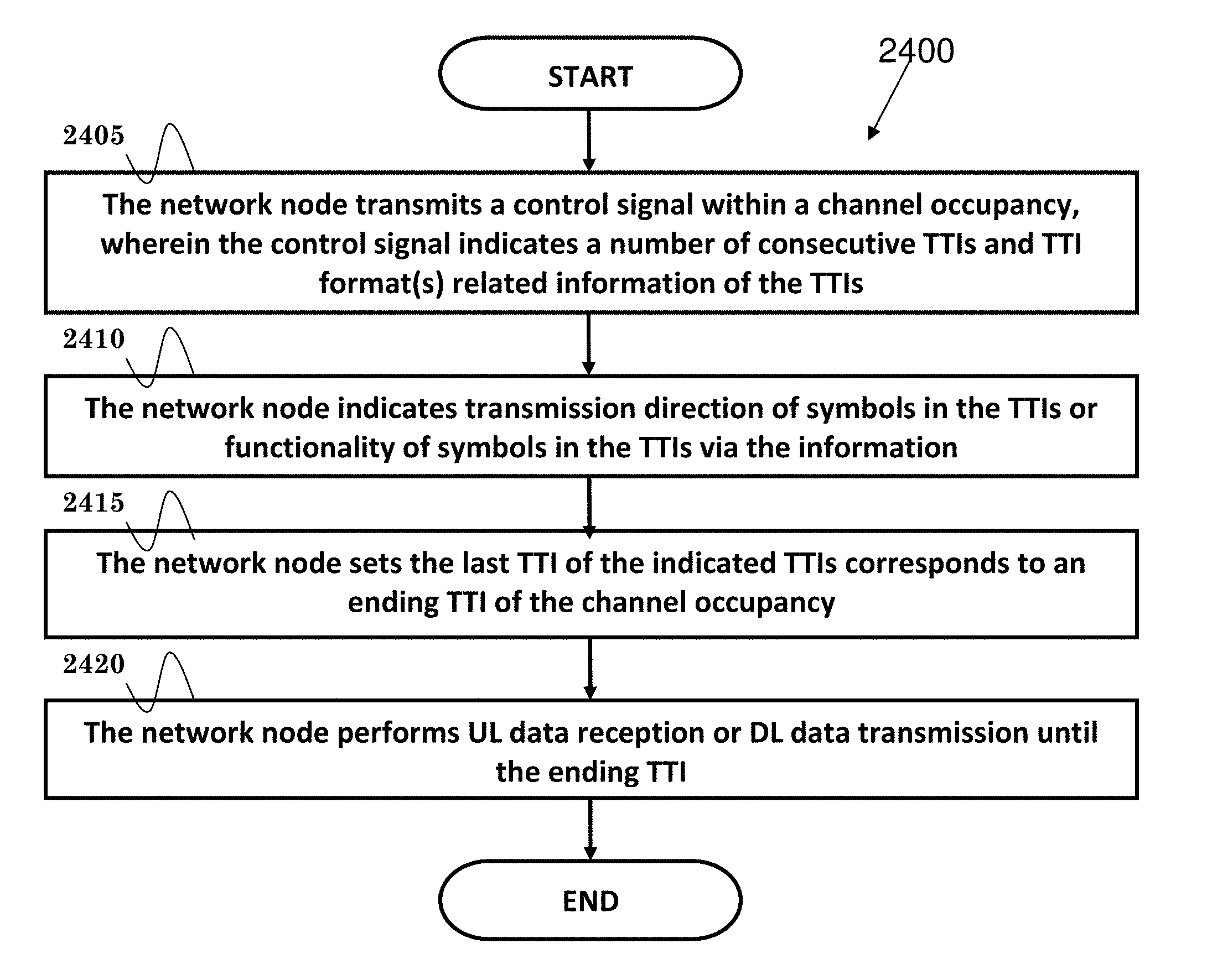
11. A method of a network node, comprising: the network node transmits a control signal within a channel occupancy, wherein the control signal indicates a number of consecutive TTIs (Transmission Time Intervals) and TTI format(s) related information of the TTIs; the network node indicates transmission direction of symbols in the TTIs or functionality of symbols in the TTIs via the information; the network node sets the last TTI of the indicated TTIs corresponds to an ending TTI of the channel occupancy; the network node performs UL (Uplink) data reception or DL (Downlink) data transmission until the ending TTI.
12. The network of claim 11, wherein the network node transmits the control signal in unlicensed spectrum or unlicensed channel or in an unlicensed cell.
13. The network of claim 11, wherein the transmission direction or functionality of symbol indicated in the information comprises at least any of "DL", "UL", "No DL and No UL", "empty", or "reserved".
14. The network of claim 11, wherein the network does not perform UL reception or DL transmission for a reference signal or a channel in symbols indicated as "No DL and No UL" or "empty" or "reserved".
15. The network of claim 11, wherein the ending TTI is the last TTI within the channel occupancy, and wherein the last TTI is a full TTI or a partial TTI, which contains a subset of symbols within a full TTI.
16. The network of claim 11, wherein the control signal indicates transmission direction or functionality of an ending symbol, wherein the ending symbol means the last symbol utilized or indicated for DL transmission or UL transmission within the ending TTI.
17. The network of claim 11, wherein the control signal is a group common control signal, e.g. SFI (Slot Format Related Information), wherein the control signal is transmitted multiple times in different timings within the channel occupancy.
18. The network of claim 11, wherein the TTI is a slot or a scheduling time unit.
19. The network of claim 11, wherein the network node performs reception or transmission before and/or in an ending symbol within the ending TTI, and does not perform UL data reception or DL data transmission after the ending symbol, until next channel occupancy.
20. The network of claim 11, wherein if the control signal is for a licensed cell or licensed channel or licensed spectrum and comprises slot format related information, the network node does not set the last TTI indicated in the control signal corresponds to the ending TTI of the channel occupancy; and wherein if the control signal is for an unlicensed cell or unlicensed channel or unlicensed spectrum and comprises slot format related information, the network node sets the last TTI indicated in the control signal corresponds to the ending TTI of the channel occupancy.
Description
CROSS-REFERENCE TO RELATED APPLICATIONS
[0001] The present Application claims the benefit of U.S. Provisional Patent Application Ser. No. 62/555,898 filed on Sep. 8, 2017, the entire disclosure of which is incorporated herein in its entirety by reference.
FIELD
[0002] This disclosure generally relates to wireless communication networks, and more particularly, to a method and apparatus for channel usage in unlicensed spectrum considering beamformed transmission in a wireless communication system.
BACKGROUND
[0003] With the rapid rise in demand for communication of large amounts of data to and from mobile communication devices, traditional mobile voice communication networks are evolving into networks that communicate with Internet Protocol (IP) data packets. Such IP data packet communication can provide users of mobile communication devices with voice over IP, multimedia, multicast and on-demand communication services.
[0004] An exemplary network structure is an Evolved Universal Terrestrial Radio Access Network (E-UTRAN). The E-UTRAN system can provide high data throughput in order to realize the above-noted voice over IP and multimedia services. A new radio technology for the next generation (e.g., 5G) is currently being discussed by the 3GPP standards organization. Accordingly, changes to the current body of 3GPP standard are currently being submitted and considered to evolve and finalize the 3GPP standard.
SUMMARY
[0005] A method and apparatus are disclosed from the perspective of a UE (User Equipment). In one embodiment, the method includes the UE monitors or receives a control signal within a channel occupancy, wherein the control signal indicates a number of consecutive TTIs (Transmission Time Intervals) and TTI format(s) related information of the TTIs. The method further includes the UE derives transmission direction of symbols in the TTIs or functionality of symbols in the TTIs from the information. The method also includes the UE considers the last TTI of the indicated TTIs as an ending TTI of the channel occupancy. In addition, the method includes the UE performs DL (Downlink) data reception or UL (Uplink) data transmission until the ending TTI.
BRIEF DESCRIPTION OF THE DRAWINGS
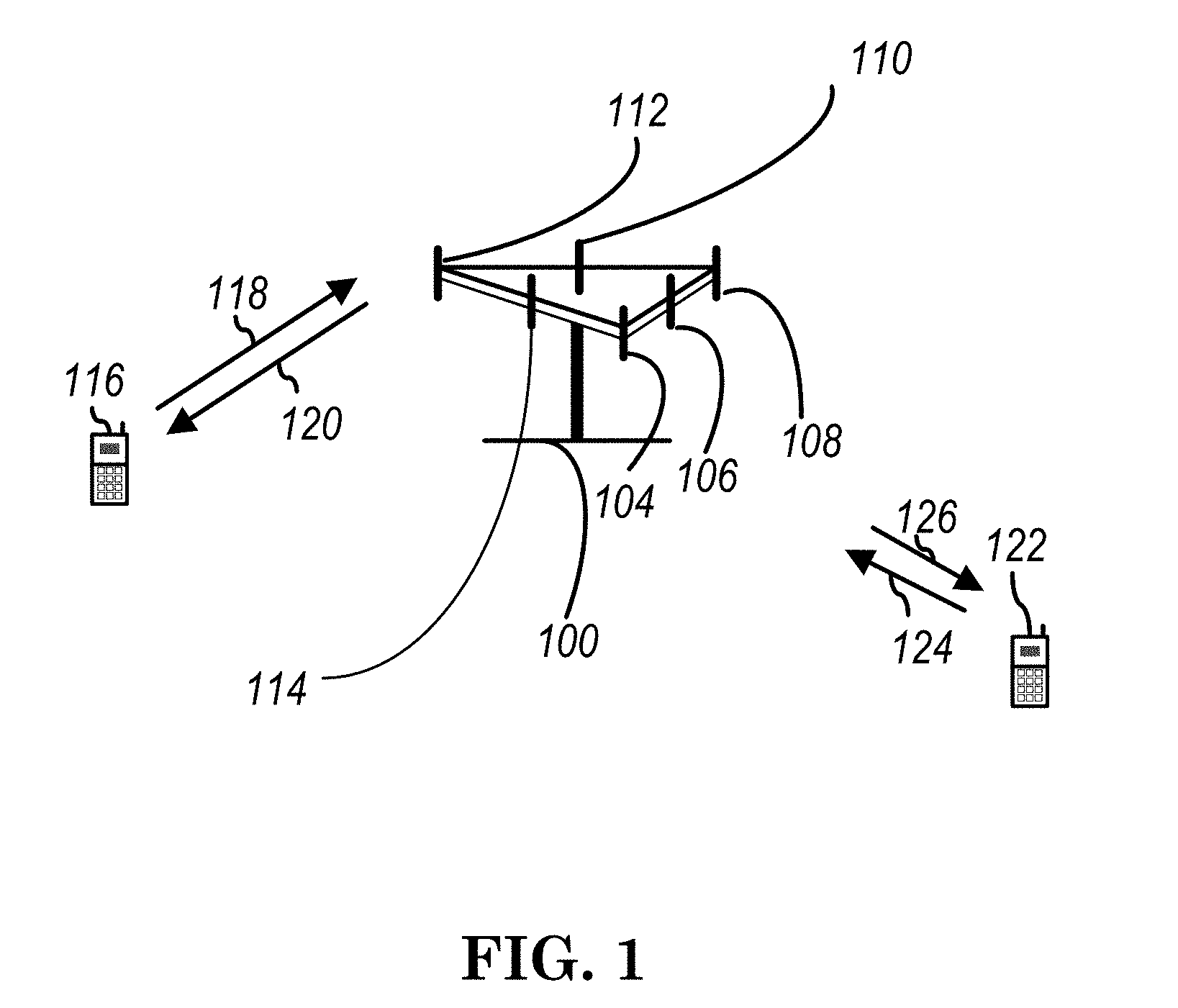
[0006] FIG. 1 shows a diagram of a wireless communication system according to one exemplary embodiment.
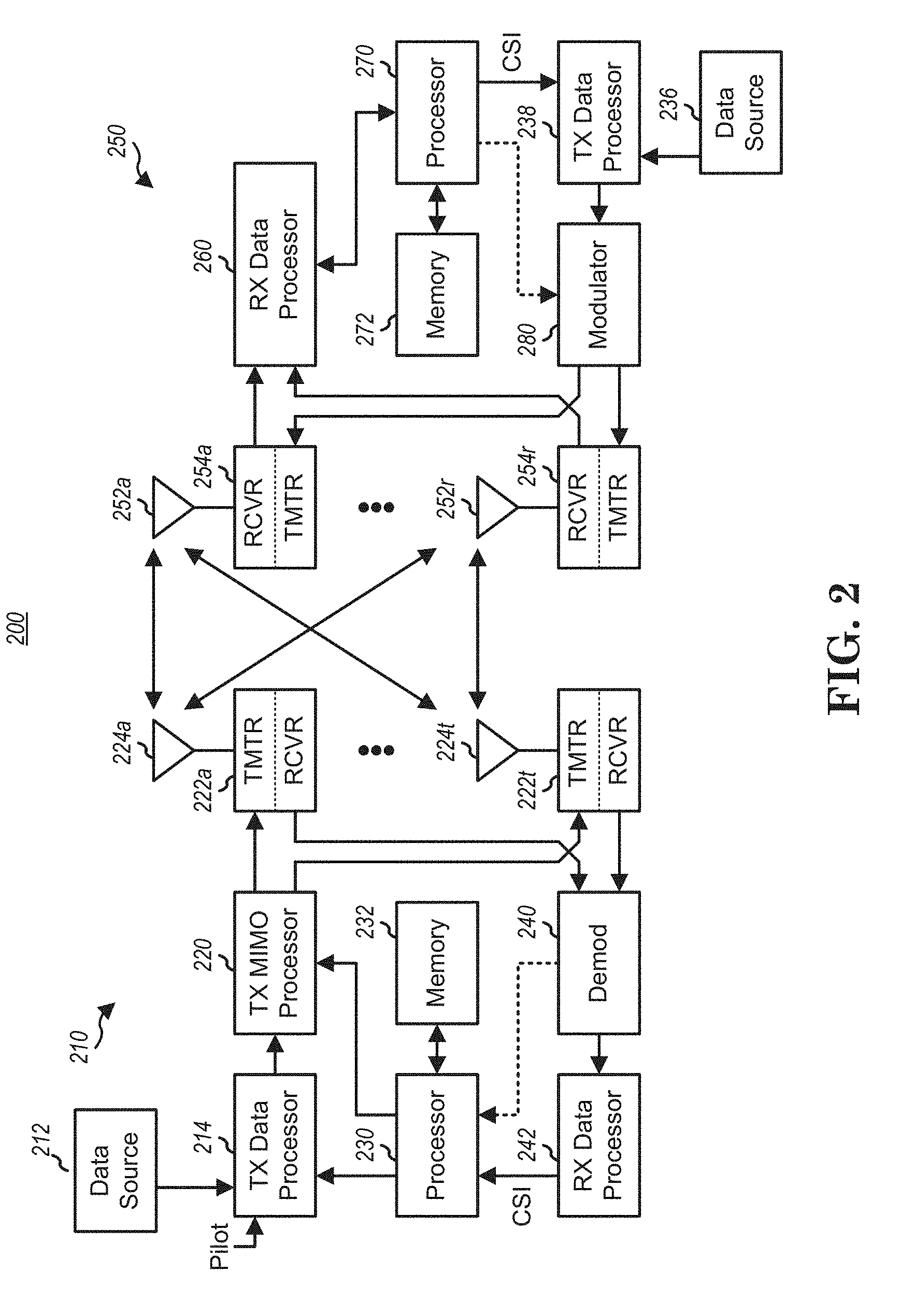
[0007] FIG. 2 is a block diagram of a transmitter system (also known as access network) and a receiver system (also known as user equipment or UE) according to one exemplary embodiment.
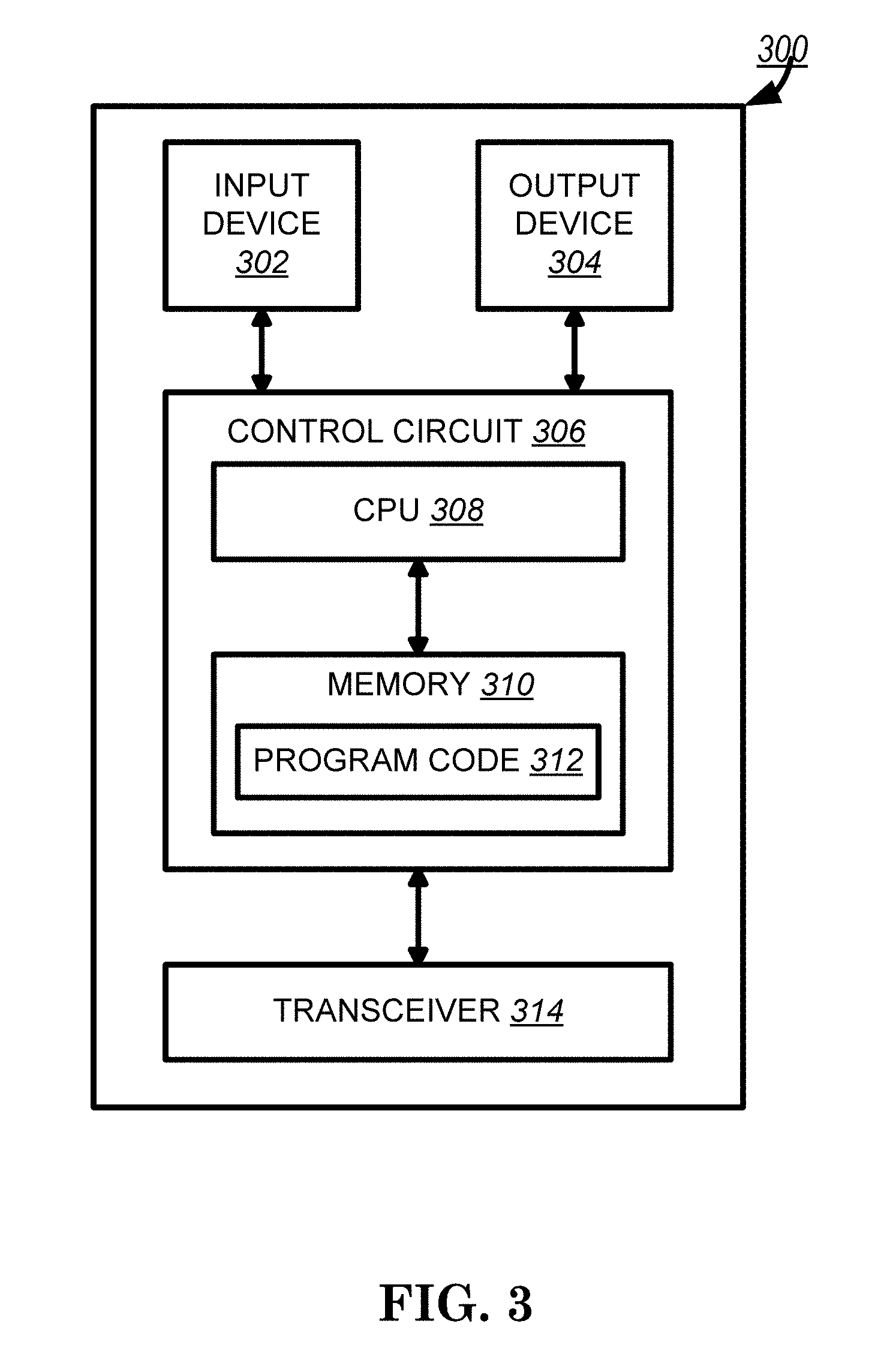
[0008] FIG. 3 is a functional block diagram of a communication system according to one exemplary embodiment.
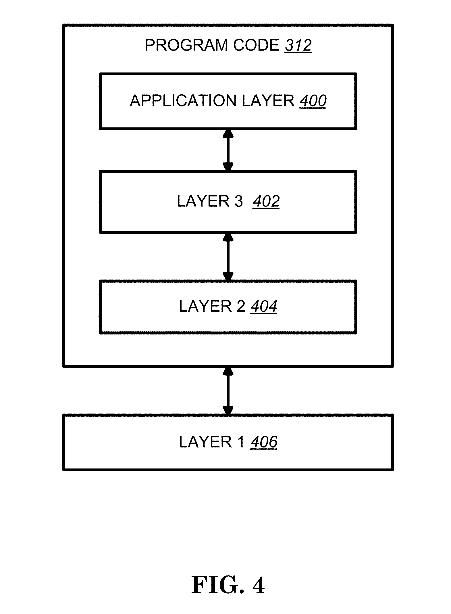
[0009] FIG. 4 is a functional block diagram of the program code of FIG. 3 according to one exemplary embodiment.
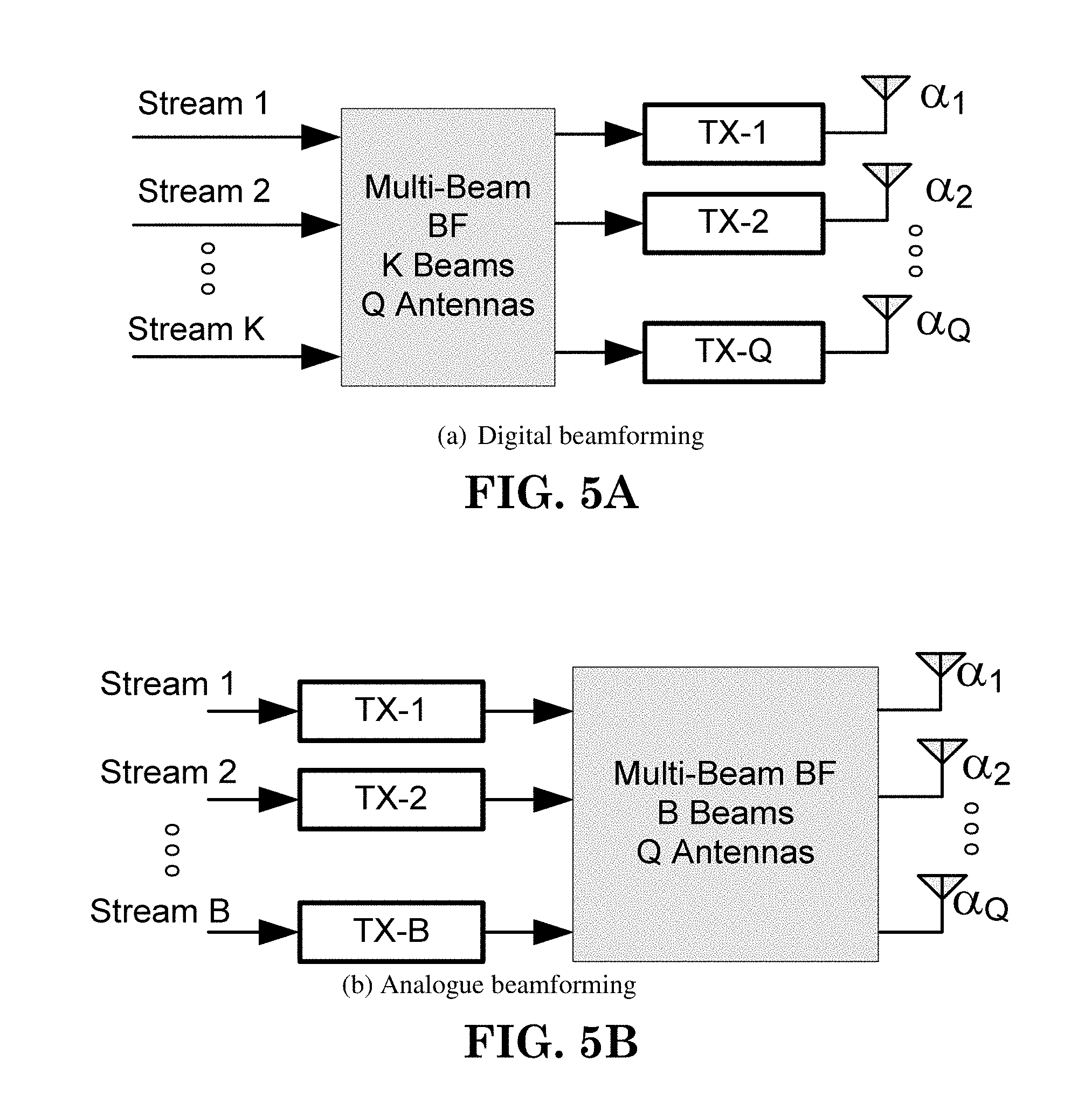
[0010] FIGS. 5A-5C provide exemplary illustrations of three types of beamforming.
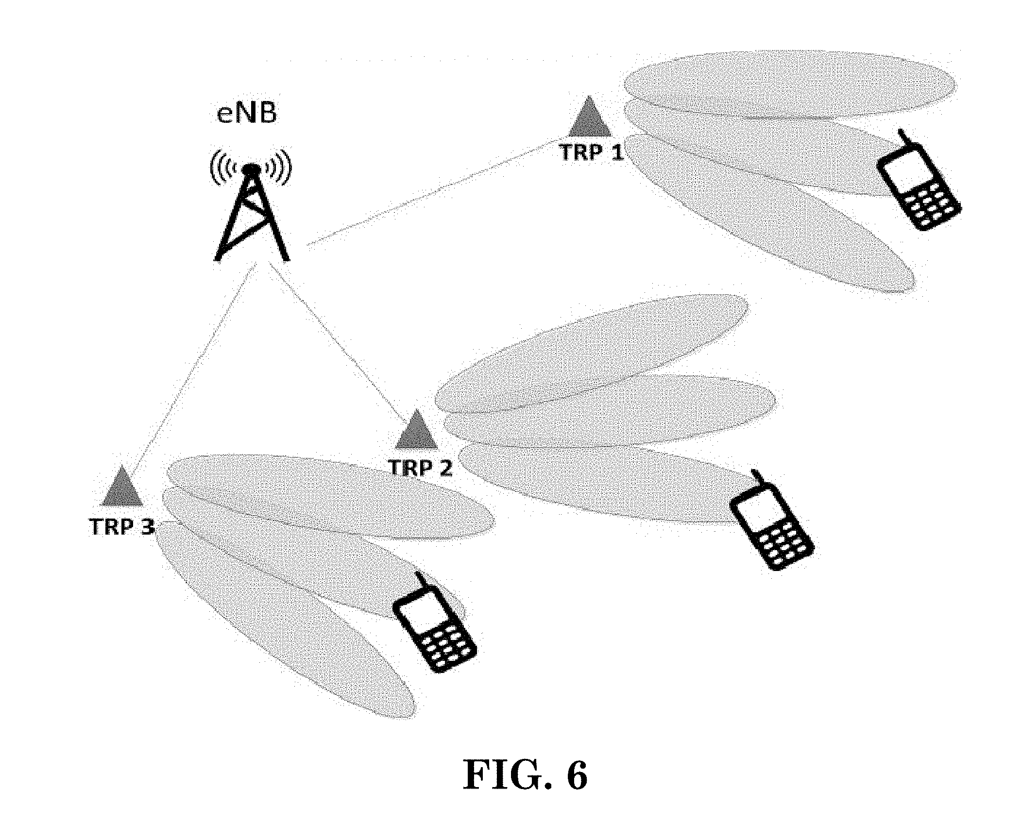
[0011] FIG. 6 is a reproduction of FIG. 1 of 3GPP R2-162709.
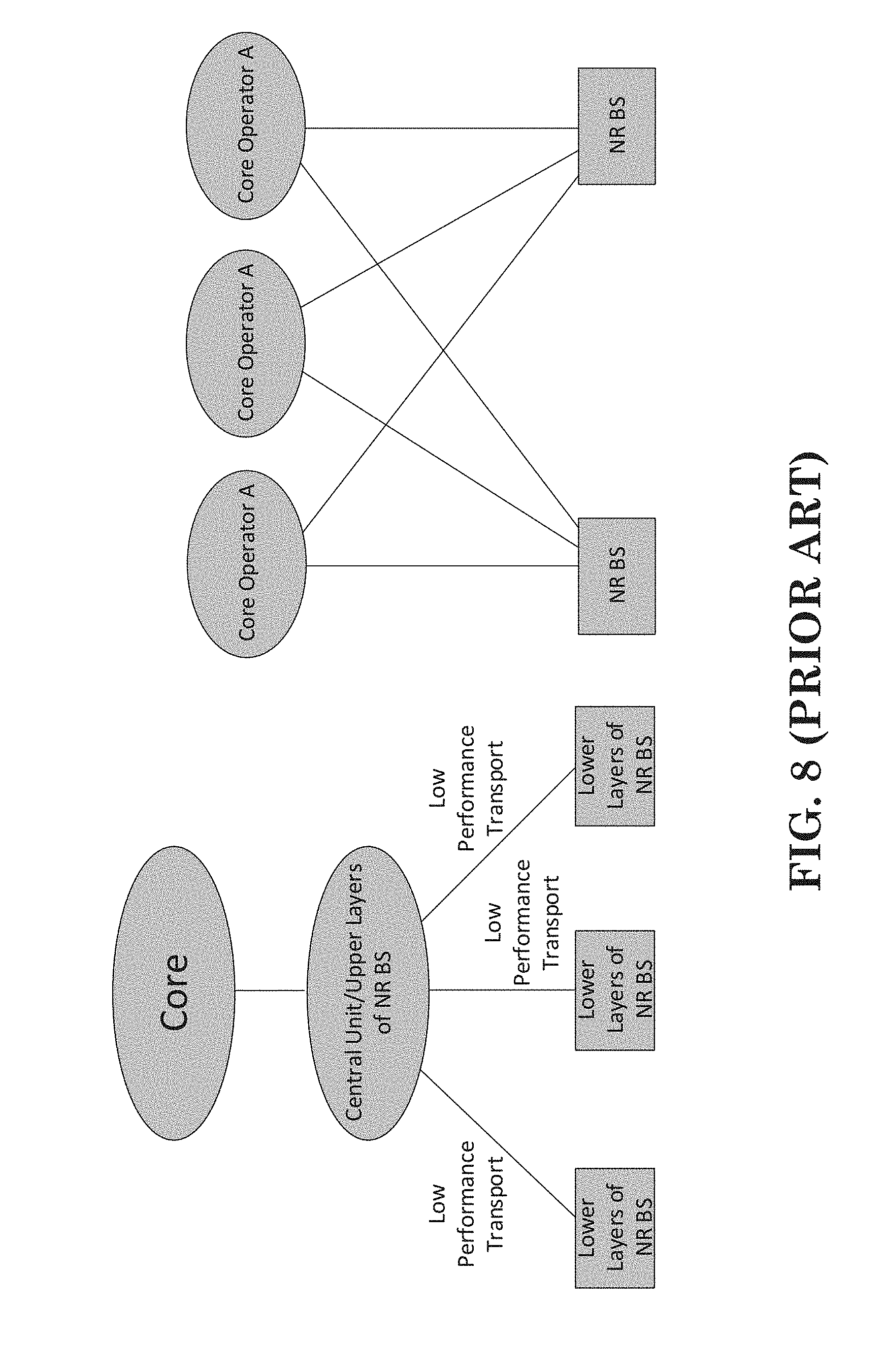
[0012] FIGS. 7 and 8 are reproduction of figures of 3GPP R2-160947.
[0013] FIG. 8 is a reproduction of FIG. 3 of 3GPP R2-162210.
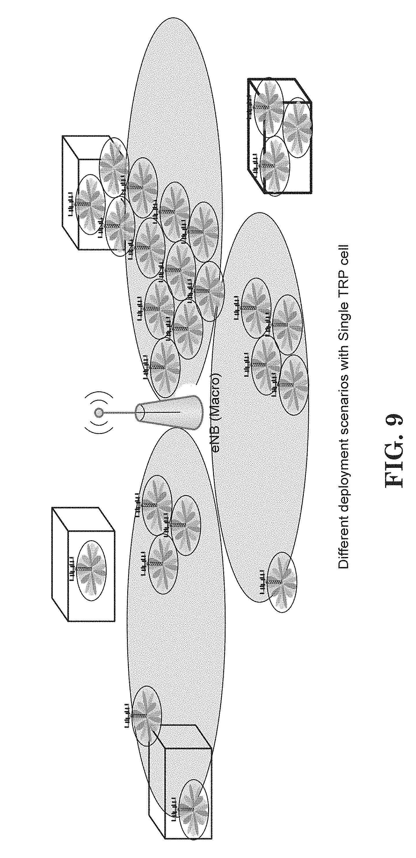
[0014] FIG. 9 shows an exemplary deployment with single TRP cell.
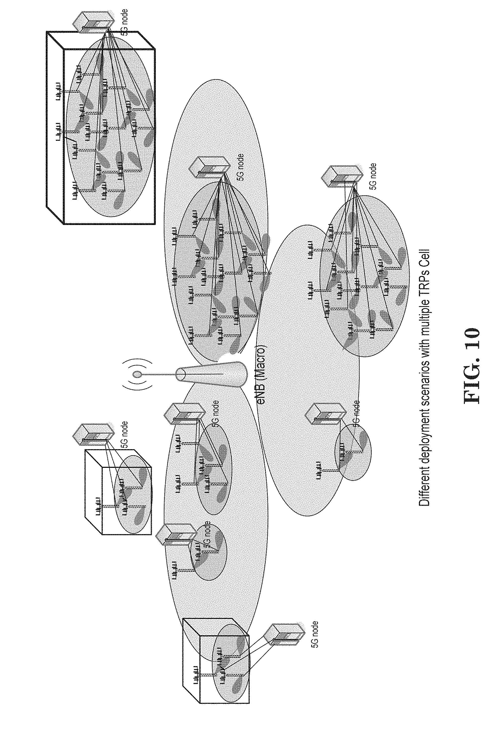
[0015] FIG. 10 shows an exemplary deployment with multiple TRP cells.
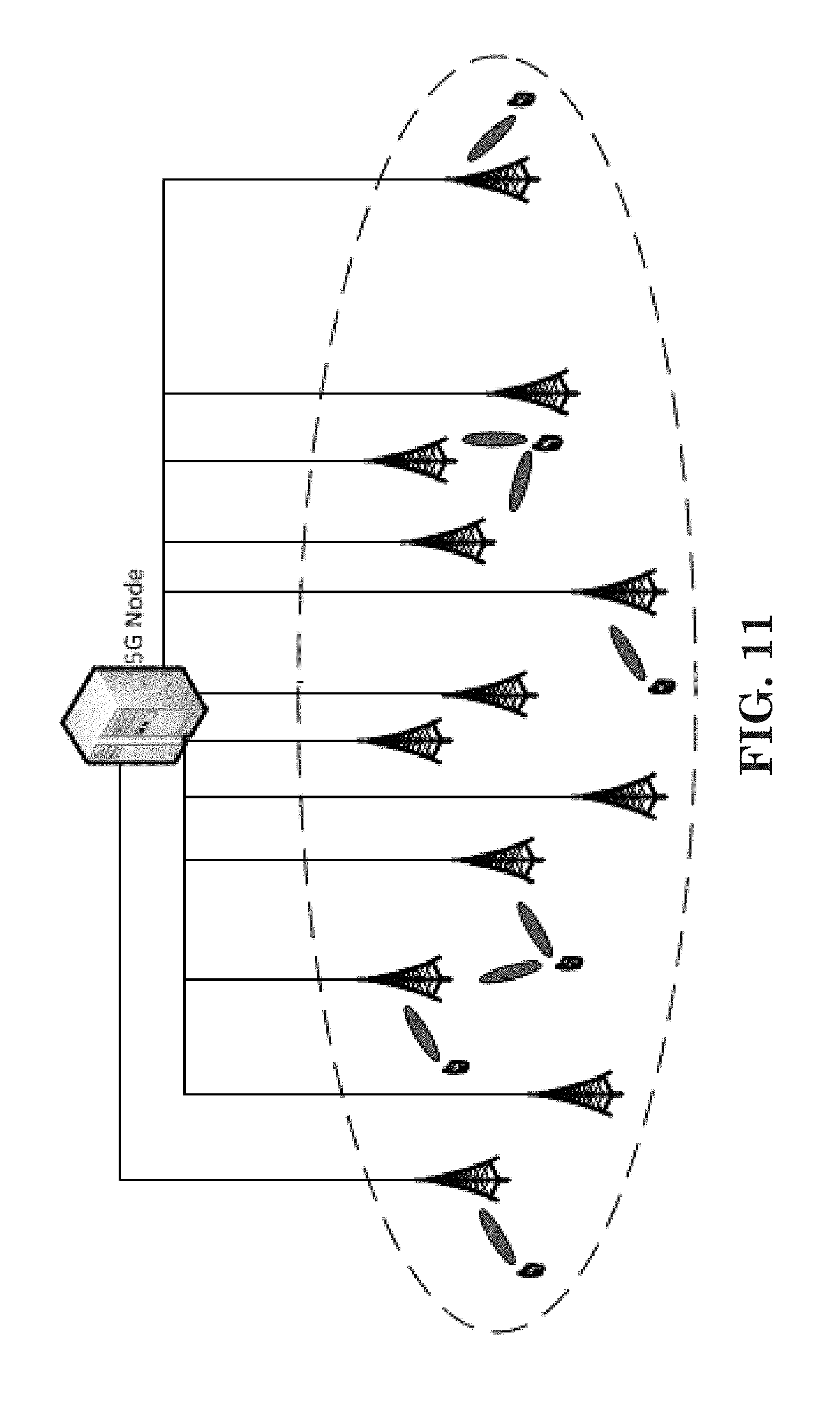
[0016] FIG. 11 shows an exemplary 5G cell comprising a 5G node with multiple TRPs.
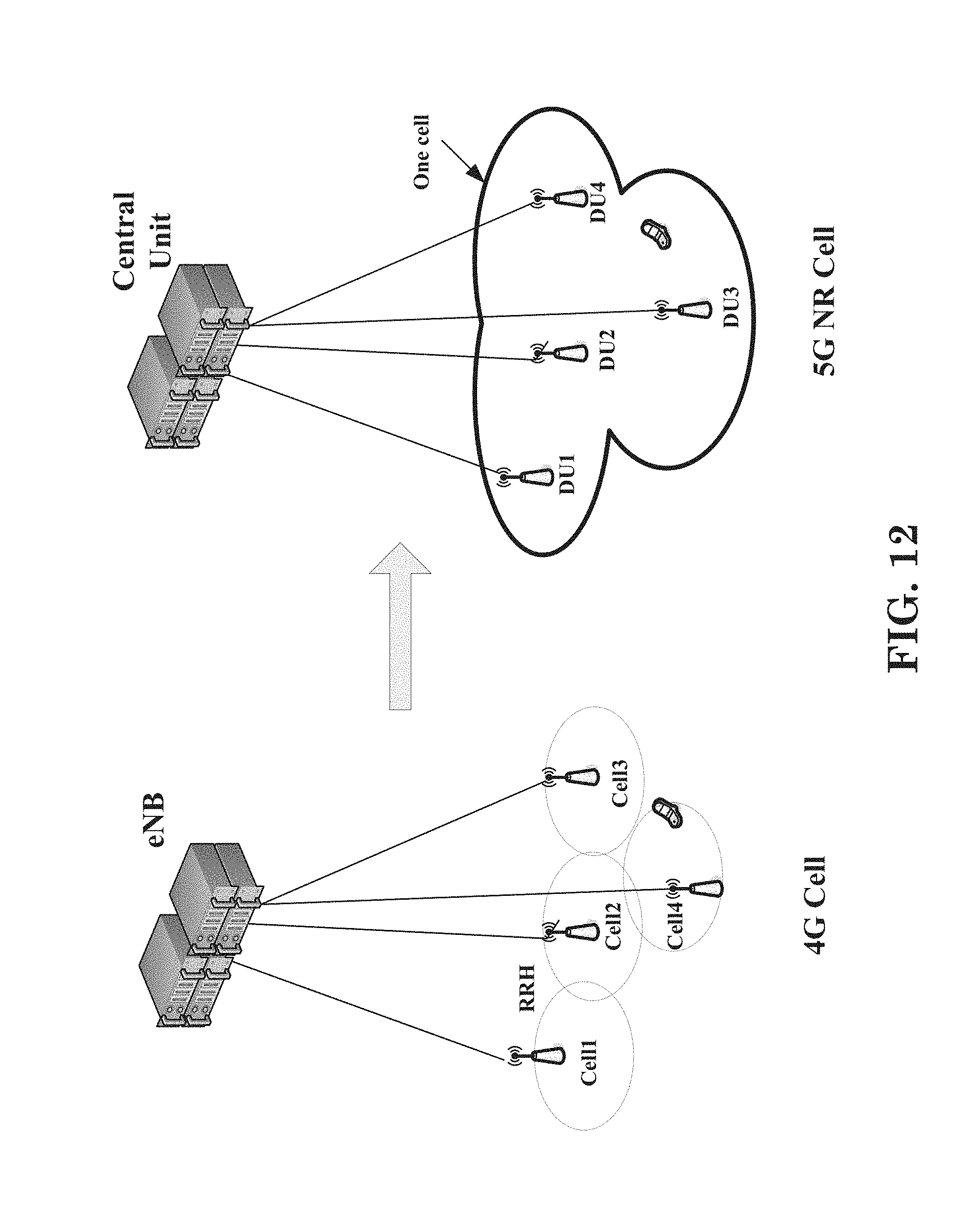
[0017] FIG. 12 shows an exemplary comparison between a LTE cell and a NR cell.
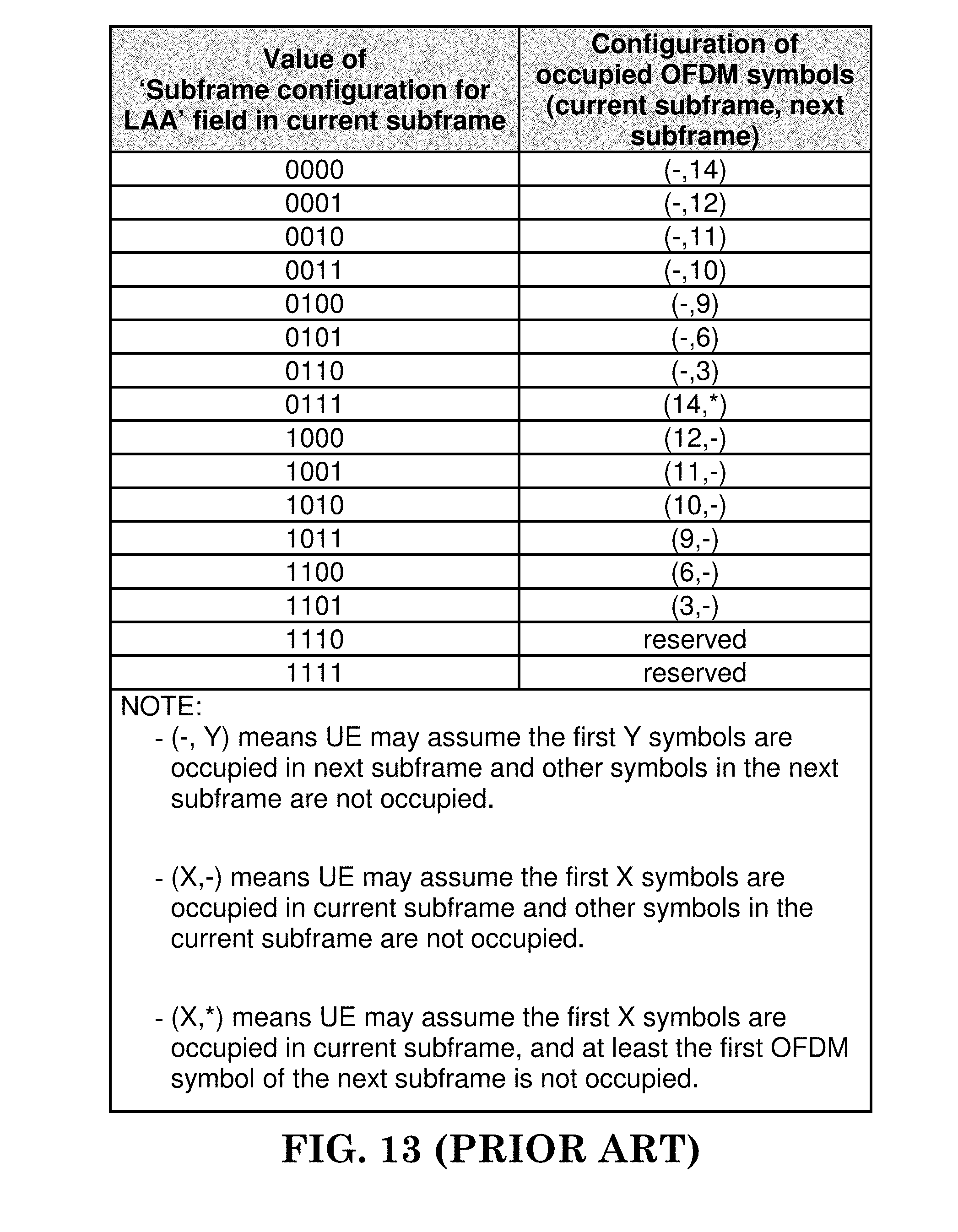
[0018] FIG. 13 is a reproduction of Table 13A-1 of 3GPP TS 36.213 V14.3.0.
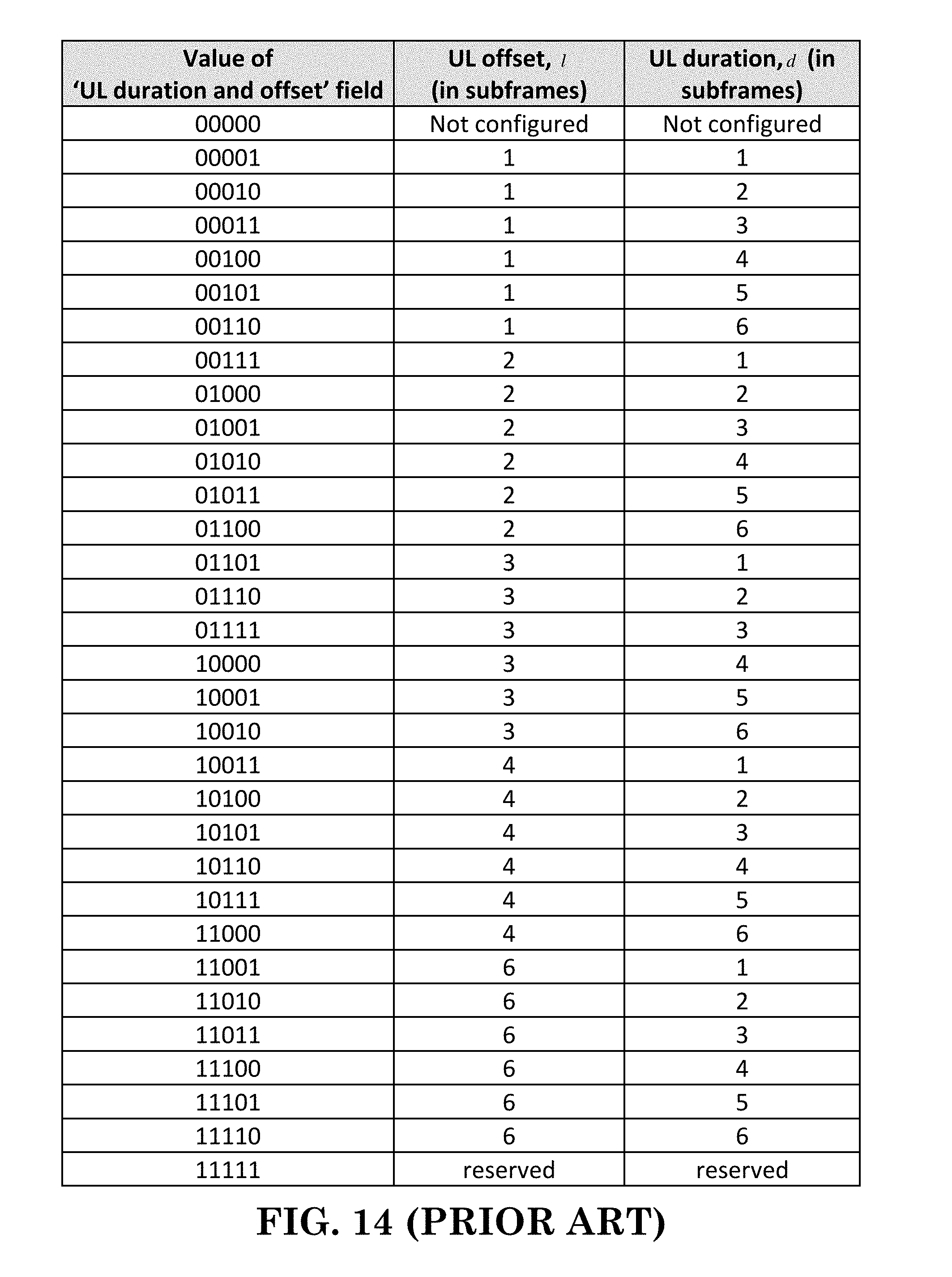
[0019] FIG. 14 is a reproduction of Table 13A-2 of 3GPP TS 36.213 V14.3.0.
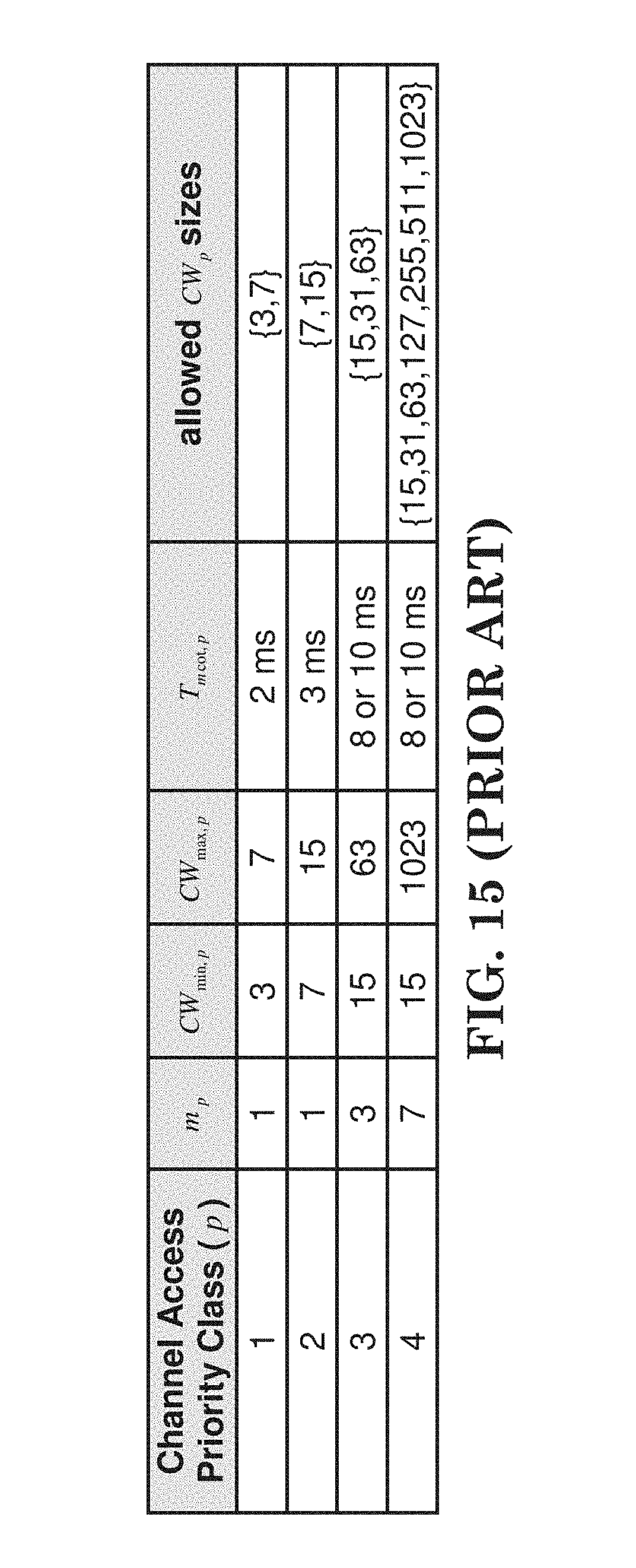
[0020] FIG. 15 is a reproduction of Table 15.1.1-1 of 3GPP TS 36.213 V14.3.0.
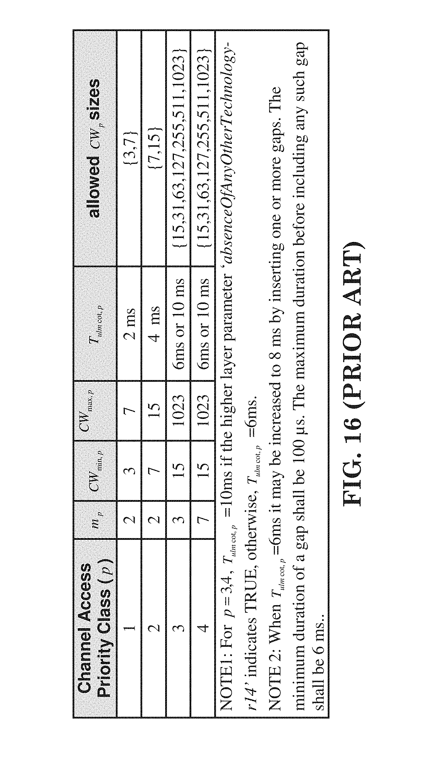
[0021] FIG. 16 is a reproduction of Table 15.2.1-1 of 3GPP TS 36.213 V14.3.0.
[0022] FIG. 17 is a reproduction of Table 5.3.3.1.1A-1 of 3GPP TS 36.212 V14.3.0.
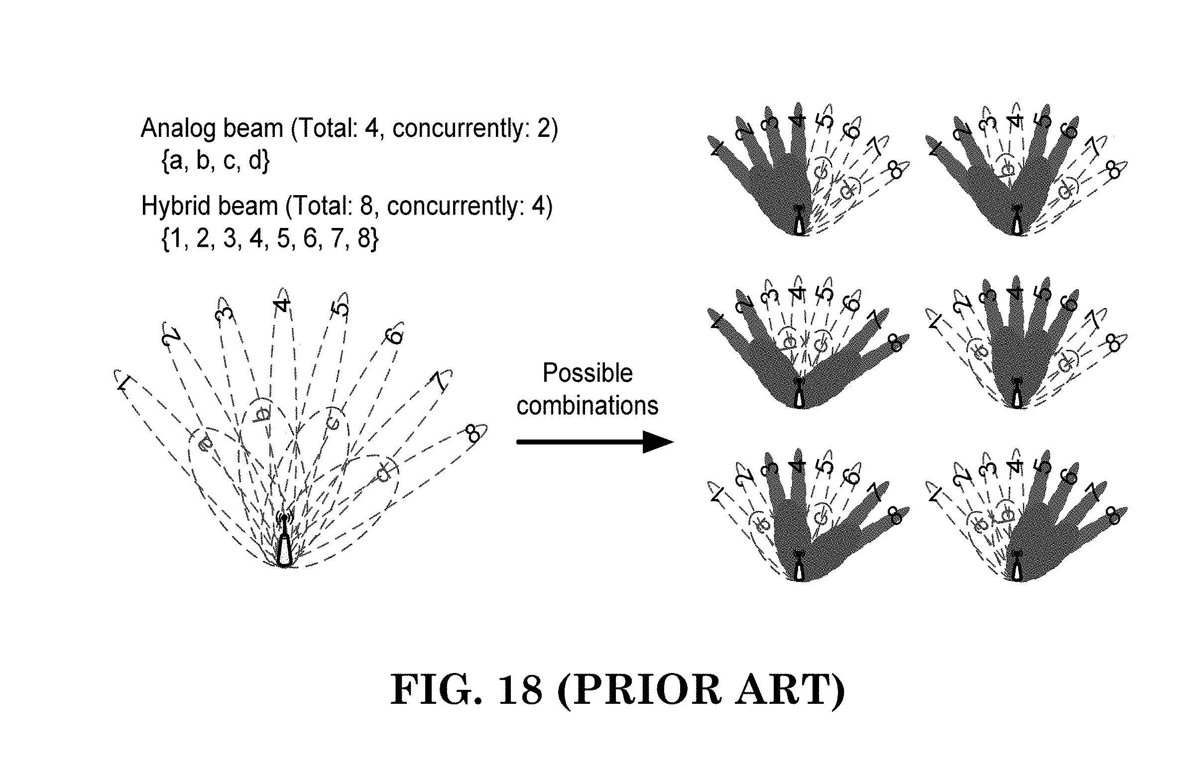
[0023] FIG. 18 shows a combination limitation of beam generation according to one exemplary embodiment.
[0024] FIG. 19 is a reproduction of FIG. 3 of 3GPP R2-162251.
[0025] FIG. 20 is a reproduction of FIG. 4 of 3GPP R2-162251.
[0026] FIG. 21 is an illustration according to one exemplary embodiment.
[0027] FIG. 22 is an illustration according to one exemplary embodiment.
[0028] FIG. 23 is a flow chart according to one exemplary embodiment.
[0029] FIG. 24 is a flow chart according to one exemplary embodiment.
[0030] FIG. 25 is a flow chart according to one exemplary embodiment.
DETAILED DESCRIPTION
[0031] The exemplary wireless communication systems and devices described below employ a wireless communication system, supporting a broadcast service. Wireless communication systems are widely deployed to provide various types of communication such as voice, data, and so on. These systems may be based on code division multiple access (CDMA), time division multiple access (TDMA), orthogonal frequency division multiple access (OFDMA), 3GPP LTE (Long Term Evolution) wireless access, 3GPP LTE-A or LTE-Advanced (Long Term Evolution Advanced), 3GPP2 UMB (Ultra Mobile Broadband), WiMax, or some other modulation techniques.
[0032] In particular, the exemplary wireless communication systems devices described below may be designed to support one or more standards such as the standard offered by a consortium named "3rd Generation Partnership Project" referred to herein as 3GPP, including: R2-162366, "Beam Forming Impacts", Nokia and Alcatel-Lucent; R2-163716, "Discussion on terminology of beamforming based high frequency NR", Samsung; R2-162709, "Beam support in NR", Intel; R2-162762, "Active Mode Mobility in NR: SINR drops in higher frequencies", Ericsson; R3-160947, TR 38.801 V0.1.0, "Study on New Radio Access Technology; Radio Access Architecture and Interfaces"; R2-164306, "Summary of email discussion [93bis#23][NR] Deployment scenarios", NTT DOCOMO, INC.; 3GPP RAN2#94 meeting minute; R2-162251, "RAN2 aspects of high frequency New RAT", Samsung; TS 36.213 V14.3.0, "E-UTRA Physical layer procedures"; TS 36.212 V14.3.0, "E-UTRA Multiplexing and channel coding"; TS 36.211 V14.3.0, "E-UTRA Physical channels and modulation"; Final Report of 3GPP TSG RAN WG1 #85 v1.0.0 (Nanjing,China, 23rd-27th May 2016); Final Report of 3GPP TSG RAN WG1 #86 v1.0.0 (Gothenburg, Sweden, 22nd-26th Aug. 2016); Final Report of 3GPP TSG RAN WG1 #86bis v1.0.0 (Lisbon, Portugal, 10th-14th Oct. 2016); Final Report of 3GPP TSG RAN WG1 #87 v1.0.0 (Reno, USA, 14th-18th November 2016); Final Report of 3GPP TSG RAN WG1 #AH1_NR v1.0.0 (Spokane, USA, 16th-20th Jan. 2017); Final Report of 3GPP TSG RAN WG1 #88 v1.0.0 (Athens, Greece, 13th-17th Feb. 2017); Final Report of 3GPP TSG RAN WG1 #88bis v1.0.0 (Spokane, USA, 3rd-7th Apr. 2017); Final Report of 3GPP TSG RAN WG1 #89 v1.0.0 (Hangzhou, China, 15th-19th May 2017); Final Report of 3GPP TSG RAN WG1 #AH NR2 v1.0.0 (Qingdao, China, 27th-30th Jun. 2017); and Final Chairman's Note of 3GPP TSG RAN WG1 Meeting #90 (Prague, Czech Republic, 21st-25th Aug. 2017). The standards and documents listed above are hereby expressly incorporated by reference in their entirety.
[0033] FIG. 1 shows a multiple access wireless communication system according to one embodiment of the invention. An access network 100 (AN) includes multiple antenna groups, one including 104 and 106, another including 108 and 110, and an additional including 112 and 114. In FIG. 1, only two antennas are shown for each antenna group, however, more or fewer antennas may be utilized for each antenna group. Access terminal 116 (AT) is in communication with antennas 112 and 114, where antennas 112 and 114 transmit information to access terminal 116 over forward link 120 and receive information from access terminal 116 over reverse link 118. Access terminal (AT) 122 is in communication with antennas 106 and 108, where antennas 106 and 108 transmit information to access terminal (AT) 122 over forward link 126 and receive information from access terminal (AT) 122 over reverse link 124. In a FDD system, communication links 118, 120, 124 and 126 may use different frequency for communication. For example, forward link 120 may use a different frequency then that used by reverse link 118.
[0034] Each group of antennas and/or the area in which they are designed to communicate is often referred to as a sector of the access network. In the embodiment, antenna groups each are designed to communicate to access terminals in a sector of the areas covered by access network 100.
[0035] In communication over forward links 120 and 126, the transmitting antennas of access network 100 may utilize beamforming in order to improve the signal-to-noise ratio of forward links for the different access terminals 116 and 122. Also, an access network using beamforming to transmit to access terminals scattered randomly through its coverage causes less interference to access terminals in neighboring cells than an access network transmitting through a single antenna to all its access terminals.
[0036] An access network (AN) may be a fixed station or base station used for communicating with the terminals and may also be referred to as an access point, a Node B, a base station, an enhanced base station, an evolved Node B (eNB), or some other terminology. An access terminal (AT) may also be called user equipment (UE), a wireless communication device, terminal, access terminal or some other terminology.
[0037] FIG. 2 is a simplified block diagram of an embodiment of a transmitter system 210 (also known as the access network) and a receiver system 250 (also known as access terminal (AT) or user equipment (UE)) in a MIMO system 200. At the transmitter system 210, traffic data for a number of data streams is provided from a data source 212 to a transmit (TX) data processor 214.
[0038] In one embodiment, each data stream is transmitted over a respective transmit antenna. TX data processor 214 formats, codes, and interleaves the traffic data for each data stream based on a particular coding scheme selected for that data stream to provide coded data.
[0039] The coded data for each data stream may be multiplexed with pilot data using OFDM techniques. The pilot data is typically a known data pattern that is processed in a known manner and may be used at the receiver system to estimate the channel response. The multiplexed pilot and coded data for each data stream is then modulated (i.e., symbol mapped) based on a particular modulation scheme (e.g., BPSK, QPSK, M-PSK, or M-QAM) selected for that data stream to provide modulation symbols. The data rate, coding, and modulation for each data stream may be determined by instructions performed by processor 230.
[0040] The modulation symbols for all data streams are then provided to a TX MIMO processor 220, which may further process the modulation symbols (e.g., for OFDM). TX MIMO processor 220 then provides N.sub.T modulation symbol streams to N.sub.T transmitters (TMTR) 222a through 222t. In certain embodiments, TX MIMO processor 220 applies beamforming weights to the symbols of the data streams and to the antenna from which the symbol is being transmitted.
[0041] Each transmitter 222 receives and processes a respective symbol stream to provide one or more analog signals, and further conditions (e.g., amplifies, filters, and upconverts) the analog signals to provide a modulated signal suitable for transmission over the MIMO channel. N.sub.T modulated signals from transmitters 222a through 222t are then transmitted from N.sub.T antennas 224a through 224t, respectively.
[0042] At receiver system 250, the transmitted modulated signals are received by N.sub.R antennas 252a through 252r and the received signal from each antenna 252 is provided to a respective receiver (RCVR) 254a through 254r. Each receiver 254 conditions (e.g., filters, amplifies, and downconverts) a respective received signal, digitizes the conditioned signal to provide samples, and further processes the samples to provide a corresponding "received" symbol stream.
[0043] An RX data processor 260 then receives and processes the N.sub.R received symbol streams from N.sub.R receivers 254 based on a particular receiver processing technique to provide N.sub.T "detected" symbol streams. The RX data processor 260 then demodulates, deinterleaves, and decodes each detected symbol stream to recover the traffic data for the data stream. The processing by RX data processor 260 is complementary to that performed by TX MIMO processor 220 and TX data processor 214 at transmitter system 210.
[0044] A processor 270 periodically determines which pre-coding matrix to use (discussed below). Processor 270 formulates a reverse link message comprising a matrix index portion and a rank value portion.
[0045] The reverse link message may comprise various types of information regarding the communication link and/or the received data stream. The reverse link message is then processed by a TX data processor 238, which also receives traffic data for a number of data streams from a data source 236, modulated by a modulator 280, conditioned by transmitters 254a through 254r, and transmitted back to transmitter system 210.
[0046] At transmitter system 210, the modulated signals from receiver system 250 are received by antennas 224, conditioned by receivers 222, demodulated by a demodulator 240, and processed by a RX data processor 242 to extract the reserve link message transmitted by the receiver system 250. Processor 230 then determines which pre-coding matrix to use for determining the beamforming weights then processes the extracted message.
[0047] Turning to FIG. 3, this figure shows an alternative simplified functional block diagram of a communication device according to one embodiment of the invention. As shown in FIG. 3, the communication device 300 in a wireless communication system can be utilized for realizing the UEs (or ATs) 116 and 122 in FIG. 1 or the base station (or AN) 100 in FIG. 1, and the wireless communications system is preferably the LTE system. The communication device 300 may include an input device 302, an output device 304, a control circuit 306, a central processing unit (CPU) 308, a memory 310, a program code 312, and a transceiver 314. The control circuit 306 executes the program code 312 in the memory 310 through the CPU 308, thereby controlling an operation of the communications device 300. The communications device 300 can receive signals input by a user through the input device 302, such as a keyboard or keypad, and can output images and sounds through the output device 304, such as a monitor or speakers. The transceiver 314 is used to receive and transmit wireless signals, delivering received signals to the control circuit 306, and outputting signals generated by the control circuit 306 wirelessly. The communication device 300 in a wireless communication system can also be utilized for realizing the AN 100 in FIG. 1.
[0048] FIG. 4 is a simplified block diagram of the program code 312 shown in FIG. 3 in accordance with one embodiment of the invention. In this embodiment, the program code 312 includes an application layer 400, a Layer 3 portion 402, and a Layer 2 portion 404, and is coupled to a Layer 1 portion 406. The Layer 3 portion 402 generally performs radio resource control. The Layer 2 portion 404 generally performs link control. The Layer 1 portion 406 generally performs physical connections.
[0049] 3GPP standardization activities on next generation (i.e. 5G) access technology have been launched since March 2015. In general, the next generation access technology aims to support the following three families of usage scenarios for satisfying both the urgent market needs and the more long-term requirements set forth by the ITU-R IMT-2020: [0050] eMBB (enhanced Mobile Broadband) [0051] mMTC (massive Machine Type Communications) [0052] URLLC (Ultra-Reliable and Low Latency Communications).
[0053] An objective of the 5G study item on new radio access technology is to identify and develop technology components needed for new radio systems which should be able to use any spectrum band ranging at least up to 100 GHz. Supporting carrier frequencies up to 100 GHz brings a number of challenges in the area of radio propagation. As the carrier frequency increases, the path loss also increases.
[0054] Based on 3GPP R2-162366, in lower frequency bands (e.g., current LTE bands <6 GHz) the required cell coverage may be provided by forming a wide sector beam for transmitting downlink common channels. However, utilizing wide sector beam on higher frequencies (>>6 GHz) the cell coverage is reduced with same antenna gain. Thus, in order to provide required cell coverage on higher frequency bands, higher antenna gain is needed to compensate the increased path loss. To increase the antenna gain over a wide sector beam, larger antenna arrays (number of antenna elements ranging from tens to hundreds) are used to form high gain beams.
[0055] As a consequence the high gain beams being narrow compared to a wide sector beam, multiple beams for transmitting downlink common channels are needed to cover the required cell area. The number of concurrent high gain beams that access point is able to form may be limited by the cost and complexity of the utilized transceiver architecture. In practice, in higher frequencies, the number of concurrent high gain beams is much less than the total number of beams required to cover the cell area. In other words, the access point is able to cover only part of the cell area by using a subset of beams at any given time.
[0056] Based on 3GPP R2-163716, beamforming is a signal processing technique used in antenna arrays for directional signal transmission/reception. With beamforming, a beam can be formed by combining elements in a phased array of antennas in such a way that signals at particular angles experience constructive interference while others experience destructive interference. Different beams can be utilized simultaneously using multiple arrays of antennas.
[0057] Beamforming can be generally categorized into three types of implementation: digital beamforming, hybrid beamforming, and analog beamforming. For digital beamforming, the beam is generated on the digital domain, i.e. the weighting of each antenna element can be controlled by baseband (e.g. connected to a TXRU (Transceiver Units)). Therefore it is very easy to tune the beam direction of each subband differently across the system bandwidth. Also, to change beam direction from time to time does not require any switching time between OFDM (Orthogonal Frequency Division Multiplexing) symbols. All beams whose directions cover the whole coverage can be generated simultaneously. However, this structure requires (almost) one-to-one mapping between TXRU (transceiver/RF chain) and antenna element and is quite complicated as the number of antenna element increases and system bandwidth increases (also heat problem exists).
[0058] For Analog beamforming, the beam is generated on the analog domain, i.e. the weighting of each antenna element can be controlled by an amplitude/phase shifter in the RF (Radio Frequency) circuit. Since the weighing is purely controlled by the circuit, the same beam direction would apply on the whole system bandwidth. Also, if beam direction is to be changed, switching time is required. The number of beams generated simultaneous by an analog beamforming depends on the number of TXRU. Note that for a given size of array, the increase of TXRU may decrease the antenna element of each beam, such that wider beam would be generated. In short, analog beamforming could avoid the complexity and heat problem of digital beamforming, while is more restricted in operation. Hybrid beamforming can be considered as a compromise between analog and digital beamforming, where the beam can come from both analog and digital domain.
[0059] FIGS. 5A-5C provide exemplary illustrations of the three types of beamforming.
[0060] Based on 3GPP R2-162709 and as shown in FIG. 6, an eNB may have multiple TRPs (either centralized or distributed). Each TRP (Transmission/Reception Point) can form multiple beams. The number of beams and the number of simultaneous beams in the time/frequency domain depend on the number of antenna array elements and the RF (Radio Frequency) at the TRP.
[0061] Potential mobility type for NR can be listed as follows: [0062] Intra-TRP mobility [0063] Inter-TRP mobility [0064] Inter-NR eNB mobility
[0065] Based on 3GPP R2-162762, reliability of a system purely relying on beamforming and operating in higher frequencies might be challenging, since the coverage might be more sensitive to both time and space variations. As a consequence of that the SINR (Signal to Interference Plus Noise Ratio) of that narrow link can drop much quicker than in the case of LTE.
[0066] Using antenna arrays at access nodes with the number of elements in the hundreds, fairly regular grid-of-beams coverage patterns with tens or hundreds of candidate beams per node may be created. The coverage area of an individual beam from such array may be small, down to the order of some tens of meters in width. As a consequence, channel quality degradation outside the current serving beam area is quicker than in the case of wide area coverage, as provided by LTE.
[0067] Based on 3GPP R3-160947, the scenarios illustrated in FIGS. 7 and 8 should be considered for support by the NR radio network architecture.
[0068] Based on 3GPP R2-164306, the following scenarios in terms of cell layout for standalone NR are captured to be studied: [0069] Macro cell only deployment [0070] Heterogeneous deployment [0071] Small cell only deployment
[0072] Based on 3GPP RAN2#94 meeting minutes, 1 NR eNB corresponds to 1 or many TRPs. Two levels of network controlled mobility: [0073] RRC driven at "cell" level. [0074] Zero/Minimum RRC involvement (e.g. at MAC/PHY)
[0075] FIGS. 9 to 12 show some examples of the concept of a cell in 5G NR. FIG. 9 shows an exemplary deployment with single TRP cell. FIG. 10 shows an exemplary deployment with multiple TRP cells. FIG. 11 shows an exemplary 5G cell comprising a 5G node with multiple TRPs. FIG. 12 shows an exemplary comparison between a LTE cell and a NR cell. [0076] FIG. 6.1.3.5-1 of 3GPP TS 36.321 v13.2.0, entitled "Timing Advance Command MAC control element", is reproduced as FIG. 23 [0077] FIG. 6.1.5-1 of 3GPP TS 36.321 v13.2.0, entitled "E/T/RAPID MAC subheader", is reproduced as FIG. 24
[0078] The LAA (Licensed-Assisted Access) subframe configuration is specified in 3GPP TS 36.213 as follows:
[0079] One or multiple of following terminologies may be used hereafter: [0080] BS: A network central unit or a network node in NR which is used to control one or multiple TRPs which are associated with one or multiple cells. Communication between BS and TRP(s) is via fronthaul. BS could also be referred to as central unit (CU), eNB, gNB, or NodeB. [0081] TRP: A transmission and reception point provides network coverage and directly communicates with UEs. TRP could also be referred to as distributed unit (DU) or network node. [0082] Cell: A cell is composed of one or multiple associated TRPs, i.e. coverage of the cell is composed of coverage of all associated TRP(s). One cell is controlled by one BS. Cell could also be referred to as TRP group (TRPG). [0083] Beam sweeping: In order to cover all possible directions for transmission and/or reception, a number of beams is required. Since it is not possible to generate all these beams concurrently, beam sweeping means to generate a subset of these beams in one time interval and change generated beam(s) in other time interval(s), i.e. changing beam in time domain. So, all possible directions can be covered after several time intervals. [0084] Beam sweeping number: A necessary number of time interval(s) to sweep beams in all possible directions once for transmission and/or reception. In other words, a signaling applying beam sweeping would be transmitted "beam sweeping number" of times within one time period, e.g. the signaling is transmitted in (at least partially) different beam(s) in different times of the time period. [0085] Serving beam: A serving beam for a UE is a beam generated by a network node, e.g. TRP, which is currently used to communicate with the UE, e.g. for transmission and/or reception. [0086] Candidate beam: A candidate beam for a UE is a candidate of a serving beam. Serving beam may or may not be candidate beam. [0087] Qualified beam: A qualified beam is a beam with radio quality, based on measuring signal on the beam, better than a threshold. [0088] The best serving beam: The serving beam with the best quality (e.g. the highest BRSRP value). [0089] The worst serving beam: The serving beam with the worst quality (e.g. the worst BRSRP value).
[0090] One or multiple of following assumptions for network side may be used hereafter: [0091] NR using beamforming could be standalone, i.e. UE can directly camp on or connect to NR. [0092] NR using beamforming and NR not using beamforming could coexist, e.g. in different cells. [0093] TRP would apply beamforming to both data and control signaling transmissions and receptions, if possible and beneficial. [0094] Number of beams generated concurrently by TRP depends on TRP capability, e.g. maximum number of beams generated concurrently by different TRPs may be different. [0095] Beam sweeping is necessary, e.g. for the control signaling to be provided in every direction. [0096] (For hybrid beamforming) TRP may not support all beam combinations, e.g. some beams could not be generated concurrently. FIG. 18 shows an example for combination limitation of beam generation. [0097] Downlink timing of TRPs in the same cell are synchronized. [0098] RRC layer of network side is in BS. [0099] TRP should support both UEs with UE beamforming and UEs without UE beamforming, e.g. due to different UE capabilities or UE releases.
[0100] One or multiple of following assumptions for UE side may be used hereafter: [0101] UE may perform beamforming for reception and/or transmission, if possible and beneficial. [0102] Number of beams generated concurrently by UE depends on UE capability, e.g. generating more than one beam is possible. [0103] Beam(s) generated by UE is wider than beam(s) generated by TRP, gNB, or eNB. [0104] Beam sweeping for transmission and/or reception is generally not necessary for user data but may be necessary for other signaling, e.g. to perform measurement. [0105] (For hybrid beamforming) UE may not support all beam combinations, e.g. some beams could not be generated concurrently. FIG. 18 shows an example for combination limitation of beam generation. [0106] Not every UE supports UE beamforming, e.g. due to UE capability or UE beamforming is not supported in NR first (few) release(s). [0107] One UE is possible to generate multiple UE beams concurrently and to be served by multiple serving beams from one or multiple TRPs of the same cell. [0108] Same or different (DL or UL) data could be transmitted on the same radio resource via different beams for diversity or throughput gain. [0109] There are at least two UE (RRC) states: connected state (or called active state) and non-connected state (or called inactive state or idle state). Inactive state may be an additional state or belong to connected state or non-connected state.
[0110] As discussed in 3GPP R2-162251, to use beamforming in both eNB and UE sides, practically, antenna gain by beamforming in eNB is considered about 15 to 30 dBi and the antenna gain of UE is considered about 3 to 20 dBi. FIG. 19, which is a reproduction of FIG. 3 of 3GPP R2-162251, illustrates gain compensation by beamforming.
[0111] From the SINR (Signal to Interference-plus-Noise Ratio) perspective, sharp beamforming reduces interference power from neighbor interferers, i.e. neighbor eNBs in downlink case or other UEs connected to neighbor eNBs. In TX beamforming case, only interference from other TXs whose current beam points the same direction to the RX will be the "effective" interference. The "effective" interference means that the interference power is higher than the effective noise power. In RX beamforming case, only interference from other TXs whose beam direction is the same to the UE's current RX beam direction will be the effective interference. FIG. 20, which is a reproduction of FIG. 4 of 3GPP R2-162251, illustrates weakened interference by beamforming.
[0112] In general, LTE has been considered successful in wireless communication in recent years. However, with cellular traffic exploding, LTE implemented in unlicensed spectrum is seen as an attractive method to provide extra traffic service by operators around the world. Hence, 3GPP has worked on developing licensed-assisted access (LAA), which means traffic can be offloaded via cells in unlicensed spectrum, assisted by cells in licensed spectrum. A workable procedure for LAA DL and UL has already developed completely in LTE Release 13 and 14 respectively. In Release 15, some enhancements about LAA transmission are also in progress until now.
[0113] In NR (New Radio Access Technology), usage in unlicensed spectrum also appears attractive to communication operators due to available wider bandwidth, especially in high frequency band. However, since the power loss due to signal penetration in high frequency band is significant, the beamforming technology in transmission and reception is essential in NR communication system.
[0114] In LTE, LAA is operated in around 5 GHz band and LBT (Listen Before Talk) is essential and regulatory to implement. With LBT before transmission, the possibility of collision with other coexisting nodes, e.g. WiFi, can be effectively reduced. For NR, the unlicensed spectrum used is even higher, which is located around 60 GHz band. In such a high frequency band, LBT technology can be an option used to provide friendly coexistence with other RATs. Indeed, LBT not only can lower the interference and reduce the collision probability with other terminals contending the same channel, but also can support coexisting friendly with other LAA nodes and other RATs, such as WiFi. Although LBT is not a mandatory requirement to implement in high frequency unlicensed spectrum (e.g. 60 GHz), LBT still provides a promising opportunity to enhance the transmission reliability and lower the successful transmission latency due to collision. Hence, NR with LBT in unlicensed spectrum seems a rational implementation.
[0115] However, unlike in omni-directional transmission, transmission/reception in LTE is implemented in a directional way in high frequency band in NR. Hence, when it comes to implementing LBT in NR, the impact from beamforming is needed to be considered. In NR, a transmitting node is possible to have multiple beams in order to serve the whole coverage, wherein each beam is oriented towards different direction and may experience different channel contending condition. Bearing it in mind, LBT in NR may be implemented independently based on respective beam. For example, one TRP has four TRP beams to serve a region. One TRP beam is capable of transmitting downlink transmission if it performs LBT successfully and grabs the channel on the one TRP beam. If LBT is not performed successfully on another one TRP beam, it is not capable of transmitting downlink transmission on the another one TRP beam. Therefore, one condition which may happen is that some TRP beams pertaining to the TRP are available to transmit, and the other TRP beams are still doing back-off procedure or trying to occupy channel. Furthermore, even though there are some TRP beams occupying the channel, the ending status of channel occupation on respective TRP beam may be different, wherein the ending status of channel occupation may comprise the position of ending subframe or slot and the amount of symbols in the ending subframe or slot.
[0116] For downlink transmission in LTE LAA, if an ending subframe is located in subframe n, network needs to indicate UE in LAA cell in subframe n-1 and subframe n, which means the previous subframe and the current subframe. The indication method is through transmitting a common control signal, and the details are provided in 3GPP TS 36.213. For NR, one explicit or implicit (signaling) method may be also needed to inform UE of which subframe or slot is the last (or ending) subframe or slot within the current channel occupancy.
[0117] It may be assumed that all beams using unlicensed spectrum, channel, or band belonging to a TRP may have the same occupation time. Due to beamformed transmission (in high frequency band), some TRP beams may face higher interference, and the other TRP beams may face idle channel instead. Hence, when all beams belonging to one TRP sense the channel (LBT) at the same time, some beams may fail the channel sensing (LBT) and cannot grab the channel. For example, one TRP has four TRP beams and performs the LBT on the four TRP beams at the same time. Two TRP beams succeed the channel sensing (LBT), which are notated as beam 1 and beam 4, and the other TRP beams fail the channel sensing (LBT), which are notated as beam 2 and beam 3. Moreover, it may require consideration on that one TRP may not be capable of performing transmission and reception (or sensing) at the same time even on different TRP beams. The situation can be further categorized into two cases as follows:
[0118] Case 1--The TRP can use the channels on Beam 1 and Beam 4 for a time duration. The TRP may perform next channel sensing (LBT) on Beam 2 and Beam 3 to try to obtain the channel usage after beam 1 and beam 4 end channel occupancy. An exemplary illustration is shown in FIG. 21.
[0119] Case 2--The TRP cannot use the channel on Beam 1 and beam 4 even the two TRP beams pass the channel sensing (LBT). All beams need to perform another LBT to grab the channel (immediately) before the next allowed transmission time instance. An exemplary illustration is shown in FIG. 22.
[0120] Regardless of which case occurs, the beam(s), which is (or are) using the unlicensed spectrum, channel, or band, should have the same occupancy time to avoid possible waste of channel utilization. Some solutions are discussed below.
[0121] Network or one TRP or gNB transmits a control signal to indicate information of ending scheduling time unit or TTI (such as ending subframe, slot, or symbol) of the TRP by the content of the control signal. A UE monitors or receives the control signal and derives information of a scheduling time unit or TTI from the control signal, wherein the information comprises transmission direction of symbol or functionality of symbol in the scheduling time unit or TTI. The UE considers the scheduling time unit or TTI as ending scheduling time unit or TTI. The UE performs DL reception or UL transmission before or within the ending scheduling time unit or TTI. In one embodiment, the UE could perform DL reception or UL transmission for a reference signal or a channel before or within the ending scheduling time unit or TTI. The UE could perform DL data reception or UL data transmission before and/or within the ending scheduling time unit or TTI until a next channel occupancy. However, the UE does not perform DL data reception or UL data transmission after the ending scheduling time unit or TTI until a next channel occupancy. In one embodiment, the next channel occupancy may be occupied or obtained by the UE or the network.
[0122] In one embodiment, the UE could monitor or receive the control signal in and unlicensed spectrum (or channel) or in an unlicensed cell (e.g. LAA cell). The transmission time(s) of the control signal is within current channel occupancy. More specifically, the ending scheduling time unit or TTI means the last scheduling time unit or TTI within the current channel occupancy. Additionally or alternatively, the ending scheduling time unit or TTI could mean the last scheduling time unit or TTI of consecutive scheduling time units or TTIs. The ending symbol means that the last symbol utilized for DL transmission or UL transmission within the ending scheduling time unit or TTI.
[0123] In one embodiment, different TRPs may transmit the control signal with different content. The ending scheduling time unit or TTI could mean the last scheduling time unit or TTI of a consecutive DL scheduling time units or TTIs or UL scheduling time units or TTIs. The control signal can be used to indicate information of any scheduling time unit or TTI of the TRP within the current channel occupancy.
[0124] In one embodiment, the control signal may be common control signal. The control signal could be transmitted by all available or occupied beams belonging to the same TRP. In particular, the control signal could be transmitted on beam(s) to explicitly or implicitly indicate the information of the ending scheduling time unit or TTI and/or ending symbol within the current channel occupancy of all available or occupied beams belonging to the TRP. The control signal could also be monitored or received and decodable by all UEs served by the beam which transmits the control signal. The beam(s) which transmit(s) the control signal could be the beam(s) that uses the unlicensed channel or unlicensed spectrum. Additionally or alternatively, the control signal could be transmitted on some of beam(s), which could be using the unlicensed channel and belong(s) to the same TRP.
[0125] In one embodiment, the control signal may not be common to the whole gNB/TRP cell. Rather, the control signal may be common control signal for a group or set of beams to the gNB or TRP cell. The UE could be configured whether to monitor/decode the control signal or not.
[0126] In one embodiment, the control signal can be a group common control signal. The control signal may carry other information in addition to information of the ending scheduling time unit or TTI and/or ending symbol of the TRP. Additionally, the control signal could include slot format related information (SFI). The control signal could also indicate the slot format related information for one or more slots. Furthermore, the control signal could indicate the UEs of the number of slots and the slot format(s) related information of those slots.
[0127] In one embodiment, the UE may monitor the control signal in licensed cell or on licensed channel. If the control signal is for a licensed cell or a licensed channel or licensed spectrum, the control signal comprises slot format related information and does not indicate ending scheduling time unit or TTI (of current channel occupancy). Alternatively or additionally, if the control signal is for an unlicensed cell or an unlicensed channel or unlicensed spectrum, the control signal comprises slot format related information and also indicates ending scheduling time unit or TTI (of current channel occupancy).
[0128] In one embodiment, the information derived from the content of the control signal could at least indicate the structure of the ending scheduling time unit or TTI. The information derived from the content of the control signal could also at least explicitly or implicitly indicate the transmission direction of symbol within the ending scheduling time unit or TTI. The transmission direction may comprise at least any of "DL", "UL", and "No DL and No UL". "DL" means DL transmission applied in the indicated symbol(s). "UL" means UL transmission applied in the indicated symbol(s). "No DL and No UL" mean no downlink transmission and no uplink transmission applied in the indicated symbol(s). Alternatively or additionally, "No DL and No UL" may mean the control signal indicates neither "DL" nor "UL" for symbol within the ending scheduling time unit or TTI. Alternatively or additionally, "No DL and No UL" may mean "empty" or "reserved".
[0129] In one embodiment, "No DL and No UL" or "empty" or "reserved" may mean that the UE does not perform transmission or reception for a reference signal or a channel in symbols indicated as "No DL and No UL" or "empty" or "reserved". Additionally, "No DL and No UL" or "empty" or "reserved" may mean that the UE does not perform transmission or reception for a reference signal with configured resources or a channel with configured resources in symbols indicated as "No DL and No UL" or "empty" or "reserved". Furthermore, "No DL and No UL" or "empty" or "reserved" may mean that the UE does not perform transmission or reception for a reference signal or a channel in symbols indicated as "No DL and No UL" or "empty" or "reserved", unless the UE receives an indication for reference signal triggering and/or data scheduling, e.g. a DCI for reference signal triggering and/or DL or UL resource assignment.
[0130] In one embodiment, "No DL and No UL" or "empty" or "reserved" may mean that the UE does not perform transmission or reception for a reference signal with configured resources or a channel with configured resources in symbols indicated as "No DL and No UL" or "empty" or "reserved", unless the UE receives an indication for reference signal triggering and/or data scheduling, e.g. a DCI for reference signal triggering and/or DL/UL resource assignment.
[0131] The way for the control signal to explicitly or implicitly indicate the timing of ending scheduling time unit or TTI and/or ending symbol can be implemented through at least two alternatives discussed below.
[0132] Alternative 1--The control signal explicitly or implicitly could indicate which one scheduling time unit or TTI in which the content of the control signal is applied. The applied scheduling time unit or TTI could be the ending scheduling time unit or TTI. Also, the applied scheduling time unit or TTI could be the ending scheduling time unit or TTI by UEs. Furthermore, the UE could assume or consider that the last symbol, which is indicated as "DL" or "UL", of the applied scheduling time unit or TTI is the ending symbol of current channel occupancy. The last symbol may be indicated as "DL" or "UL." The last symbol may not be indicated as "No DL and No UL".
[0133] In one embodiment, the control signal could indicate which one subframe or slot in which the content of the control signal is applied by a timing offset relative to the reception of the control signal. The control signal can be transmitted multiple times in different timings (e.g. different subframes or slots) within the current channel occupancy. Furthermore, the control signal can be transmitted periodically within the current channel occupancy. The information of the ending scheduling time unit or TTI indicated in these multiple or periodically transmitted control signals should be consistent and apply to the same scheduling time unit or TTI, which is the ending scheduling time unit or TTI.
[0134] In one embodiment, the network, TRP, or gNB does not indicate scheduling time unit/TTI other than the ending scheduling time unit/TTI in the control signal.
[0135] Alternative 2--The control signal could explicitly or implicitly indicate a time duration which comprises a consecutive of scheduling time units or TTIs, wherein the content of the control signal applies to these scheduling time units or TTIs. The UE could assume the last scheduling time unit or TTI in the time duration is the ending scheduling time unit or TTI. Additionally, the UE could assume or consider the last symbol indicated as "DL" or "UL" of the last scheduling time units or TTI in the time duration is the ending symbol of current channel occupancy. The last symbol may be indicated as "DL" or "UL." The last symbol may not be indicated as "No DL and No UL".
[0136] In one embodiment, the control signal can indicate the time duration by indicating starting scheduling time unit or TTI of the time duration and length of the time duration by unit of scheduling time unit or TTI. The control signal can also indicate the time duration by indicating the earliest scheduling time unit or TTI and the last scheduling time unit or TTI of the time duration.
[0137] In one embodiment, the earliest scheduling time unit or TTI can be indicated through the timing offset relative to the transmission/reception of the control signal. Alternatively, the earliest scheduling time unit or TTI could be the scheduling time unit or TTI of transmitting or receiving the control signal, or could be indicated by index of the scheduling time unit or TTI. Alternatively, the earliest scheduling time unit or TTI could be the first scheduling time unit or TTI of the current channel occupancy or the first scheduling time unit or TTI of the consecutive DL or UL scheduling time unit or TTI.
[0138] In one embodiment, the last scheduling time unit or TTI can be indicated through the timing offset relative to the reception of the control signal. Alternatively, the last scheduling time unit or TTI could be indicated by index of the scheduling time unit or TTI.
[0139] In one embodiment, the control signal can be transmitted multiple times in different timings (e.g. different subframes or slots) within the current channel occupancy. Furthermore, the control signal can be transmitted periodically within the current channel occupancy. The information of the ending scheduling time unit or TTI and/or ending symbol indicated in these multiple or periodically transmitted control signals should be consistent and imply the same last scheduling time unit or TTI with respective indicated time durations. The time duration indicated in the multiple or periodical control signals may be different.
[0140] In one embodiment, the network or TRP or gNB does not indicate and set scheduling time units or TTIs other than the ending scheduling time unit or TTI as the last scheduling time unit or TTI in the time duration indicated in the control signal.
[0141] In one embodiment, the scheduling time unit or TTI could mean a slot, a subframe, or a mini-slot.
[0142] In one embodiment, the TRP, gNB, or network could perform channel sensing (LBT) on a beam before a transmission. In particular, the TRP, gNB, or network could perform channel sensing (LBT) on a beam to assure the channel is clear, and could occupy the channel for a time duration if the channel is assured as clear.
[0143] In one embodiment, "channel occupancy" could mean a time interval within which a wireless node occupied an unlicensed channel and the wireless node is allowed to transmit in the unlicensed channel, wherein the wireless node may be a network node, or a UE node.
[0144] In one embodiment of Alternative 1, within the current channel occupancy, the network could transmit the common control signal to indicate information of a subframe or slot, which is the ending subframe. The information indicates that symbol #0 to symbol #7 are DL symbols, and the other symbols, symbol #8 to symbol #13, are No DL and No UL, assuming one subframe or slot contains 14 symbols. Then, the UE assumes the applied subframe or slot is the ending subframe or slot. The structure of the ending subframe/slot follows information in the common control signal. Symbol #0 to symbol #7 are occupied and used for DL transmission. The other symbols are unoccupied. A similar embodiment can be implemented for Alternative 2.
[0145] In one embodiment, the "subframe" or "slot" can be other scheduling time unitor TTI, such as mini-slot.
[0146] In one embodiment, the scheduling time unit or TTI indicated in the control signal may be partial. A partial scheduling time unit or TTI could mean a scheduling time unit or TTI which contains a subset of symbols within one scheduling time unit or TTI. For example, a full scheduling time unit or TTI may contain 14 symbols and a partial scheduling time unit or TTI may contain number of symbols smaller than 14.
[0147] In one embodiment, the control signals could be transmitted in different channel occupancy may carry different or the same content.
[0148] It should be noted that the disclosed solutions can be used to resolve how to indicate information of any one scheduling time unit or TTI of one beam in a TRP or cell. The disclosed solution can also be used to resolve: how to indicate information of multiple scheduling time units or TTIs of one beam in a TRP or cell.
[0149] In one embodiment, the information can be used to indicate the amount of symbols in the scheduling time unit or TTI.
[0150] In one embodiment, the beam in this invention may mean a TRP beam, and could be a TRP DL beam or a TRP UL beam.
[0151] FIG. 23 is a flow chart 2300 according to one exemplary embodiment from the perspective of a UE. In step 2305, the UE monitors or receives a control signal within a channel occupancy, wherein the control signal indicates a number of consecutive TTIs (Transmission Time Intervals) and TTI format(s) related information of the TTIs. In one embodiment, the UE could monitor or receive the control signal in unlicensed spectrum or unlicensed channel or in an unlicensed cell. The control signal could indicate transmission direction or functionality of an ending symbol, and wherein the ending symbol means the last symbol utilized or indicated for DL transmission or UL transmission within the ending TTI. Furthermore, the control signal could be a group common control signal, e.g. SFI, and wherein the control signal is transmitted multiple times in different timings within the channel occupancy. In one embodiment, if the control signal is for a licensed cell or licensed channel or licensed spectrum and comprises slot format related information, the UE does not consider the last TTI indicated in the control signal as the ending TTI of a channel occupancy; and wherein if the control signal is for an unlicensed cell or unlicensed channel or unlicensed spectrum and comprises slot format related information, the UE considers the last TTI indicated in the control signal is the ending TTI of the channel occupancy.
[0152] In step 2310, the UE derives transmission direction of symbols in the TTIs or functionality of symbols in the TTIs from the information. In one embodiment, the transmission direction or functionality of symbol could be indicated in the information comprises at least any of "DL", "UL", "No DL and No UL", "empty", or "reserved".
[0153] In step 2315, the UE considers the last TTI of the indicated TTIs as an ending TTI of the channel occupancy. In one embodiment, the ending TTI could be the last TTI within the channel occupancy, and wherein the last TTI may be a full TTI or a partial TTI that contains a subset of symbols within a full TTI.
[0154] In step 2320, the UE performs DL (Downlink) data reception or UL (Uplink) data transmission until the ending TTI. In one embodiment, the UE does not perform transmission or reception for a reference signal or a channel in symbols indicated as "No DL and No UL" or "empty" or "reserved" unless the UE receives an indication for reference signal triggering and/or data scheduling. In one embodiment, the UE could perform DL data reception or UL data transmission before and/or in an ending symbol within the ending TTI, and does not perform reception or transmission after the ending symbol, until next channel occupancy.
[0155] In one embodiment, the TTI could be a slot or a scheduling time unit.
[0156] Referring back to FIGS. 3 and 4, in one exemplary embodiment of a UE, the device 300 includes a program code 312 stored in the memory 310. The CPU 308 could execute program code 312 to enable the UE (i) to monitor or receive a control signal within a channel occupancy, wherein the control signal indicates a number of consecutive TTIs and TTI format(s) related information of the TTIs, (ii) to derive transmission direction of symbols in the TTIs or functionality of symbols in the TTIs from the information, (iii) to consider the last TTI of the indicated TTIs as an ending TTI of the channel occupancy, and (iv) to performs DL data reception or UL data transmission until the ending TTI. Furthermore, the CPU 308 can execute the program code 312 to perform all of the above-described actions and steps or others described herein.
[0157] FIG. 24 is a flow chart 2400 according to one exemplary embodiment from the perspective of a network node. In step 2405, the network node transmits a control signal within a channel occupancy, wherein the control signal indicates a number of consecutive TTIs and TTI format(s) related information of the TTIs. In one embodiment, the network node could transmit the control signal in unlicensed spectrum or unlicensed channel or in an unlicensed cell. The control signal indicates transmission direction or functionality of an ending symbol, wherein the ending symbol means the last symbol utilized or indicated for DL transmission or UL transmission within the ending TTI. The control signal could also be a group common control signal, e.g. SFI, wherein the control signal is transmitted multiple times in different timings within the channel occupancy. The TTI could be a slot or a scheduling time unit.
[0158] In step 2410, the network node indicates transmission direction of symbols in the TTIs or functionality of symbols in the TTIs via the information. In one embodiment, the transmission direction or functionality of symbol could be indicated in the information comprises at least any of "DL", "UL", "No DL and No UL", "empty", or "reserved".
[0159] In step 2415, the network node sets the last TTI of the indicated TTIs corresponds to an ending TTI of the channel occupancy.
[0160] In step 2420, the network node performs UL data reception or DL data transmission until the ending TTI. In one embodiment, the network does not perform UL reception or DL transmission for a reference signal or a channel in symbols indicated as "No DL and No UL" or "empty" or "reserved". The ending TTI could be the last TTI within a channel occupancy, and wherein the last TTI may be a partial TTI, which contains a subset of symbols within a full TTI.
[0161] In one embodiment, the network node could perform reception or transmission before and/or in an ending symbol within the ending TTI, and does not perform UL data reception or DL data transmission after the ending symbol, until next channel occupancy.
[0162] In one embodiment, if the control signal is for a licensed cell or licensed channel or licensed spectrum and comprises slot format related information, the network node does not set the last TTI indicated in the control signal corresponds to the ending TTI of the channel occupancy; and if the control signal is for an unlicensed cell or unlicensed channel or unlicensed spectrum and comprises slot format related information, the network node sets the last TTI indicated in the control signal corresponds to the ending TTI of the channel occupancy.
[0163] Referring back to FIGS. 3 and 4, in one exemplary embodiment of a network node, the device 300 includes a program code 312 stored in the memory 310. The CPU 308 could execute program code 312 to enable the network node (i) to transmit a control signal within a channel occupancy, wherein the control signal indicates a number of consecutive TTIs and TTI format(s) related information of the TTIs, (ii) to indicate transmission direction of symbols in the TTIs or functionality of symbols in the TTIs via the information, (iii) to set the last TTI of the indicated TTIs corresponds to an ending TTI of the channel occupancy, and (iv) to perform UL data reception or DL data transmission until the ending TTI. Furthermore, the CPU 308 can execute the program code 312 to perform all of the above-described actions and steps or others described herein.
[0164] FIG. 25 is a flow chart 2500 according to one exemplary embodiment from the perspective of a UE. In step 2505, the UE monitors or receives a control signal. In one embodiment, the UE could monitor or receive the control signal in unlicensed spectrum/channel or in an unlicensed cell. The transmission time(s) of the control signal could be within current channel occupancy.
[0165] In one embodiment, the control signal could be common control signal. The control signal could be transmitted by all available or occupied beams belonging to the same TRP. The control signal is received and decodable by all UEs served by the same TRP transmitting the control signal. The control signal could be transmitted on some of beam(s), which is/are using the unlicensed channel and belong(s) to the same TRP.
[0166] In one embodiment, the control signal may not be common to the whole gNB or TRP cell. The control signal could be a common control signal for a group or set of beams to the gNB or TRP cell. The UE could be configured to monitor or decode the control signal or not.
[0167] In one embodiment, the control signal could be a group common control signal. Different TRPs could transmit the control signal with different content.
[0168] In one embodiment, the time duration indicated in the multiple or periodical control signals are different. The control signal does not indicate scheduling time unit or TTI other than the ending scheduling time unit or TTI as the last scheduling time unit or TTI in the time duration indicated in the control signal.
[0169] In step 2510, the UE derives information of a scheduling time unit or TTI from the control signal, wherein the information comprises transmission direction of symbol or functionality of symbol in the scheduling time unit or TTI. In one embodiment, the information derived from the control signal indicates the structure of the scheduling time unit or TTI.
[0170] In one embodiment, the transmission direction or functionality of symbol indicated in the information comprises at least any of "DL", "UL" or "No DL and No UL". "DL" could mean downlink transmission applied in the indicated symbol(s). "UL" could mean uplink transmission applied in the indicated symbol(s). "No DL and No UL" could mean no downlink transmission and no uplink transmission applied in the indicated symbol(s). Alternatively, "No DL and No UL" could mean "empty" or "reserved".
[0171] In one embodiment, the control signal could indicate which scheduling time unit or TTI where the information is applied. The control signal could also indicate which scheduling time unit or TTI where the information is applied by a timing offset relative to the reception of the control signal.
[0172] In one embodiment, the control signal could be transmitted multiple times in different timings within the current channel occupancy. The control signal could be transmitted periodically.
[0173] In one embodiment, the information derived from the multiple or periodically transmitted control signals (within the same channel occupancy) are consistent. Furthermore, the information, which is derived from the multiple or periodically transmitted control signals (within the same channel occupancy), could apply to the same scheduling time unit or TTI.
[0174] In one embodiment, the control signal does not indicate scheduling time unit/TTI other than the ending scheduling time unit or TTI. The control signal could be used to indicate information of any scheduling time units or TTIs within the current channel occupancy. Furthermore, the control signal could indicate a time duration which comprises a consecutive of scheduling time units or TTIs, wherein the content of the control signal applies to the scheduling time units or TTIs. The UE could assume the last scheduling time unit or TTI in the time duration is the ending scheduling time unit or TTI.
[0175] In one embodiment, the control signal could indicate the time duration by indicating starting scheduling time unit or TTI of the time duration and length of the time duration by unit of scheduling time unit or TTI. The control signal could also indicate the time duration by indicating the earliest scheduling time unit or TTI and the last scheduling time unit or TTI of the time duration.
[0176] In one embodiment, the earliest scheduling time unit or TTI could be indicated through the timing offset relative to the transmission or reception of the control signal. The earliest scheduling time unit or TTI could also be the scheduling time unit or TTI of transmitting or receiving the control signal. Furthermore, the earliest scheduling time unit or TTI could be indicated by index of the scheduling time unit or TTI. In addition, the earliest scheduling time unit or TTI could be the first scheduling time unit or TTI of the current channel occupancy or the first scheduling time unit or TTI of the consecutive DL or UL scheduling time unit or TTI.
[0177] In one embodiment, the control signal could be transmitted multiple times in different timings within the current channel occupancy. The control signal could be transmitted periodically.
[0178] In one embodiment, the information derived from the multiple or periodically transmitted control signals (within the same channel occupancy) are consistent. Furthermore, the information derived from the multiple or periodically transmitted control signals (within the same channel occupancy) could apply to the same one last scheduling time unit/TTI.
[0179] In step 2515, the UE considers the scheduling time unit or TTI as an ending scheduling time unit or TTI. In one embodiment, the ending scheduling time unit or TTI is the last scheduling time unit or TTI within the current channel occupancy. The ending scheduling time unit or TTI could be the last scheduling time unit or TTI of a consecutive scheduling time units or TTIs. The ending symbol within the ending scheduling time unit or TTI could be the last symbol indicated as "DL" or "UL" of the scheduling time unit or TTI.
[0180] In one embodiment, the last scheduling time unit or TTI could be indicated through the timing offset relative to the reception of the control signal. Alternatively, the last scheduling time unit or TTI could be indicated by index of the scheduling time unit or TTI.
[0181] In step 2520, the UE performs reception or transmission before or within the ending scheduling time unit or TTI. In one embodiment, the TRP, gNB, or network could perform channel sensing (LBT) on a beam before transmission. The TRP, gNB, or network could perform channel sensing (LBT) on a beam to assure the channel is clear. Furthermore, the TRP, gNB, or network could occupy the channel for a time duration if the channel is assured as clear.
[0182] In one embodiment, the control signal could include slot format related information (SFI). More specifically, the control signal could indicate the slot format related information for one or more slots. Alternatively, the control signal could indicate the UEs of the number of slots and the slot format(s) related information of those slots.
[0183] In one embodiment, the UE could monitor the control signal in a licensed cell or on a licensed channel. If the control signal is for a licensed cell or licensed channel or licensed spectrum, the control signal could include slot format related information and does not indicate ending scheduling time unit or TTI (of current channel occupancy). Alternatively, if the control signal is for an unlicensed cell or unlicensed channel or unlicensed spectrum, the control signal could include slot format related information and could also indicates ending scheduling time unit or TTI (of current channel occupancy).
[0184] In one embodiment, the scheduling time unit or TTI could mean slot, subframe, or mini-slot.
[0185] Referring back to FIGS. 3 and 4, in one exemplary embodiment of a UE, the device 300 includes a program code 312 stored in the memory 310. The CPU 308 could execute program code 312 to enable the UE (i) to monitor or receive a control signal, (ii) to derive information of a scheduling time unit or TTI from the control signal, wherein the information comprises transmission direction of symbol or functionality of symbol in the scheduling time unit or TTI, (iii) to consider the scheduling time unit or TTI as an ending scheduling time unit or TTI, or (iv) to perform reception or transmission before or within the ending scheduling time unit or TTI. Furthermore, the CPU 308 can execute the program code 312 to perform all of the above-described actions and steps or others described herein.
[0186] Various aspects of the disclosure have been described above. It should be apparent that the teachings herein may be embodied in a wide variety of forms and that any specific structure, function, or both being disclosed herein is merely representative. Based on the teachings herein one skilled in the art should appreciate that an aspect disclosed herein may be implemented independently of any other aspects and that two or more of these aspects may be combined in various ways. For example, an apparatus may be implemented or a method may be practiced using any number of the aspects set forth herein. In addition, such an apparatus may be implemented or such a method may be practiced using other structure, functionality, or structure and functionality in addition to or other than one or more of the aspects set forth herein. As an example of some of the above concepts, in some aspects concurrent channels may be established based on pulse repetition frequencies. In some aspects concurrent channels may be established based on pulse position or offsets. In some aspects concurrent channels may be established based on time hopping sequences. In some aspects concurrent channels may be established based on pulse repetition frequencies, pulse positions or offsets, and time hopping sequences.
[0187] Those of skill in the art would understand that information and signals may be represented using any of a variety of different technologies and techniques. For example, data, instructions, commands, information, signals, bits, symbols, and chips that may be referenced throughout the above description may be represented by voltages, currents, electromagnetic waves, magnetic fields or particles, optical fields or particles, or any combination thereof.
[0188] Those of skill would further appreciate that the various illustrative logical blocks, modules, processors, means, circuits, and algorithm steps described in connection with the aspects disclosed herein may be implemented as electronic hardware (e.g., a digital implementation, an analog implementation, or a combination of the two, which may be designed using source coding or some other technique), various forms of program or design code incorporating instructions (which may be referred to herein, for convenience, as "software" or a "software module"), or combinations of both. To clearly illustrate this interchangeability of hardware and software, various illustrative components, blocks, modules, circuits, and steps have been described above generally in terms of their functionality. Whether such functionality is implemented as hardware or software depends upon the particular application and design constraints imposed on the overall system. Skilled artisans may implement the described functionality in varying ways for each particular application, but such implementation decisions should not be interpreted as causing a departure from the scope of the present disclosure.
[0189] In addition, the various illustrative logical blocks, modules, and circuits described in connection with the aspects disclosed herein may be implemented within or performed by an integrated circuit ("IC"), an access terminal, or an access point. The IC may comprise a general purpose processor, a digital signal processor (DSP), an application specific integrated circuit (ASIC), a field programmable gate array (FPGA) or other programmable logic device, discrete gate or transistor logic, discrete hardware components, electrical components, optical components, mechanical components, or any combination thereof designed to perform the functions described herein, and may execute codes or instructions that reside within the IC, outside of the IC, or both. A general purpose processor may be a microprocessor, but in the alternative, the processor may be any conventional processor, controller, microcontroller, or state machine. A processor may also be implemented as a combination of computing devices, e.g., a combination of a DSP and a microprocessor, a plurality of microprocessors, one or more microprocessors in conjunction with a DSP core, or any other such configuration.
[0190] It is understood that any specific order or hierarchy of steps in any disclosed process is an example of a sample approach. Based upon design preferences, it is understood that the specific order or hierarchy of steps in the processes may be rearranged while remaining within the scope of the present disclosure. The accompanying method claims present elements of the various steps in a sample order, and are not meant to be limited to the specific order or hierarchy presented.
[0191] The steps of a method or algorithm described in connection with the aspects disclosed herein may be embodied directly in hardware, in a software module executed by a processor, or in a combination of the two. A software module (e.g., including executable instructions and related data) and other data may reside in a data memory such as RAM memory, flash memory, ROM memory, EPROM memory, EEPROM memory, registers, a hard disk, a removable disk, a CD-ROM, or any other form of computer-readable storage medium known in the art. A sample storage medium may be coupled to a machine such as, for example, a computer/processor (which may be referred to herein, for convenience, as a "processor") such the processor can read information (e.g., code) from and write information to the storage medium. A sample storage medium may be integral to the processor. The processor and the storage medium may reside in an ASIC. The ASIC may reside in user equipment. In the alternative, the processor and the storage medium may reside as discrete components in user equipment. Moreover, in some aspects any suitable computer-program product may comprise a computer-readable medium comprising codes relating to one or more of the aspects of the disclosure. In some aspects a computer program product may comprise packaging materials.
[0192] While the invention has been described in connection with various aspects, it will be understood that the invention is capable of further modifications. This application is intended to cover any variations, uses or adaptation of the invention following, in general, the principles of the invention, and including such departures from the present disclosure as come within the known and customary practice within the art to which the invention pertains.
* * * * *
D00000
D00001
D00002
D00003
D00004
D00005
D00006
D00007
D00008
D00009
D00010
D00011
D00012
D00013
D00014
D00015
D00016
D00017
D00018
D00019

D00020
D00021

D00022

D00023
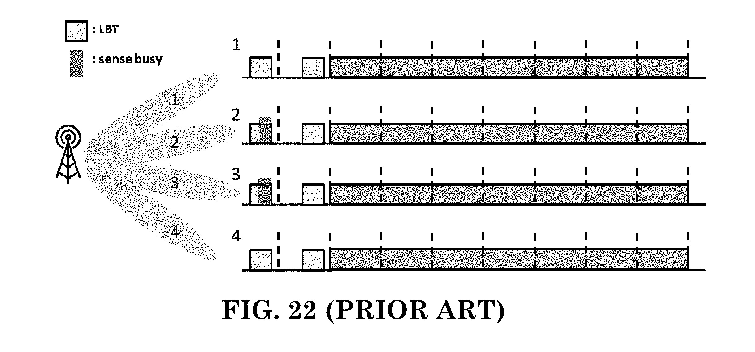
D00024
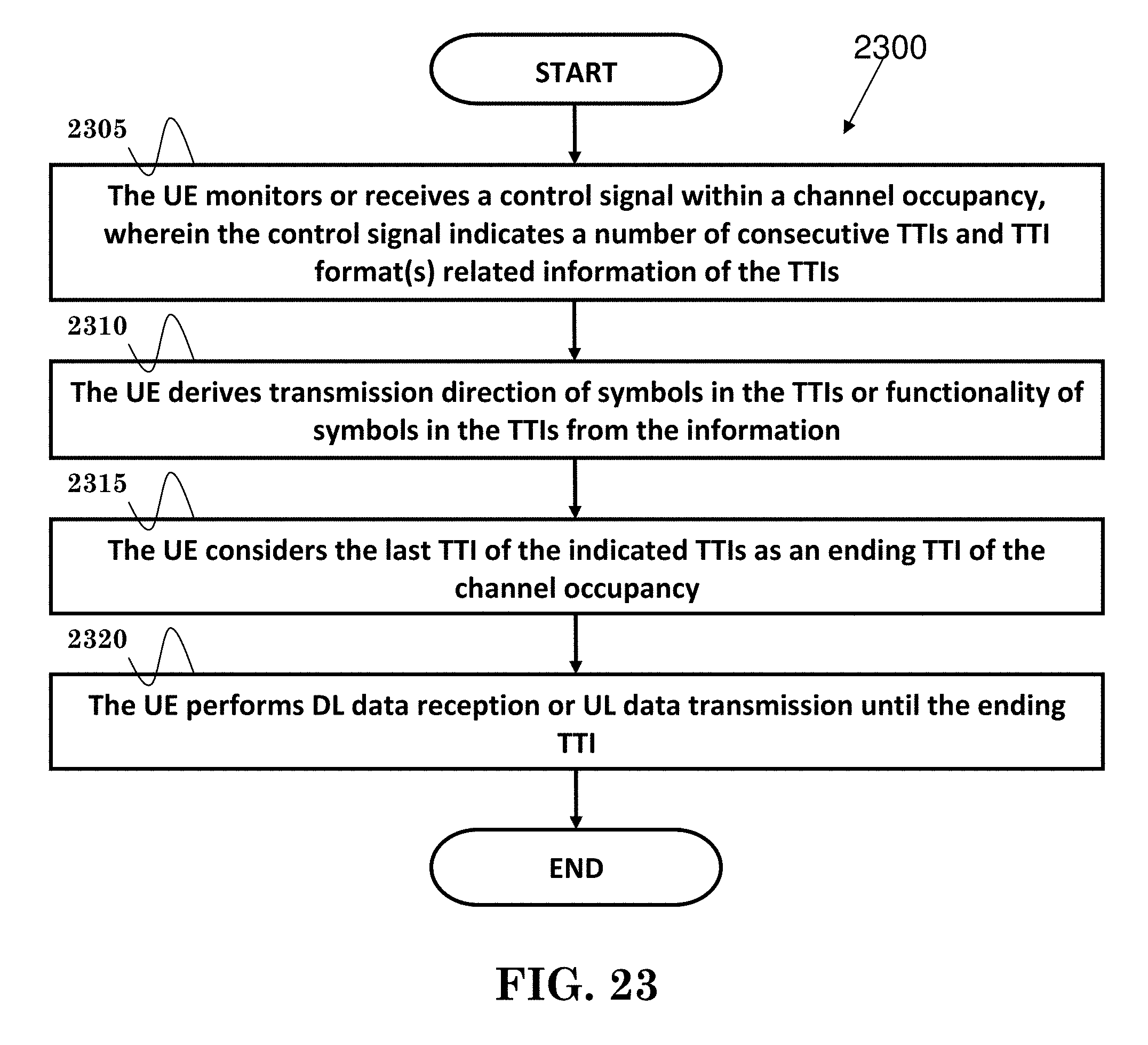
D00025
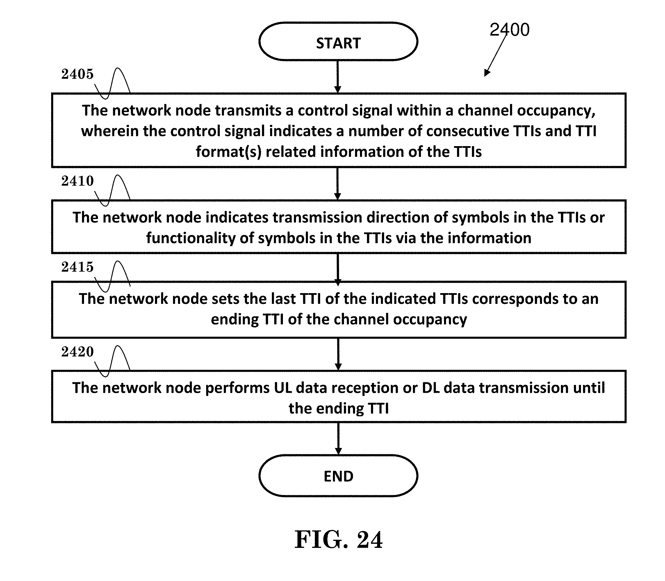
D00026
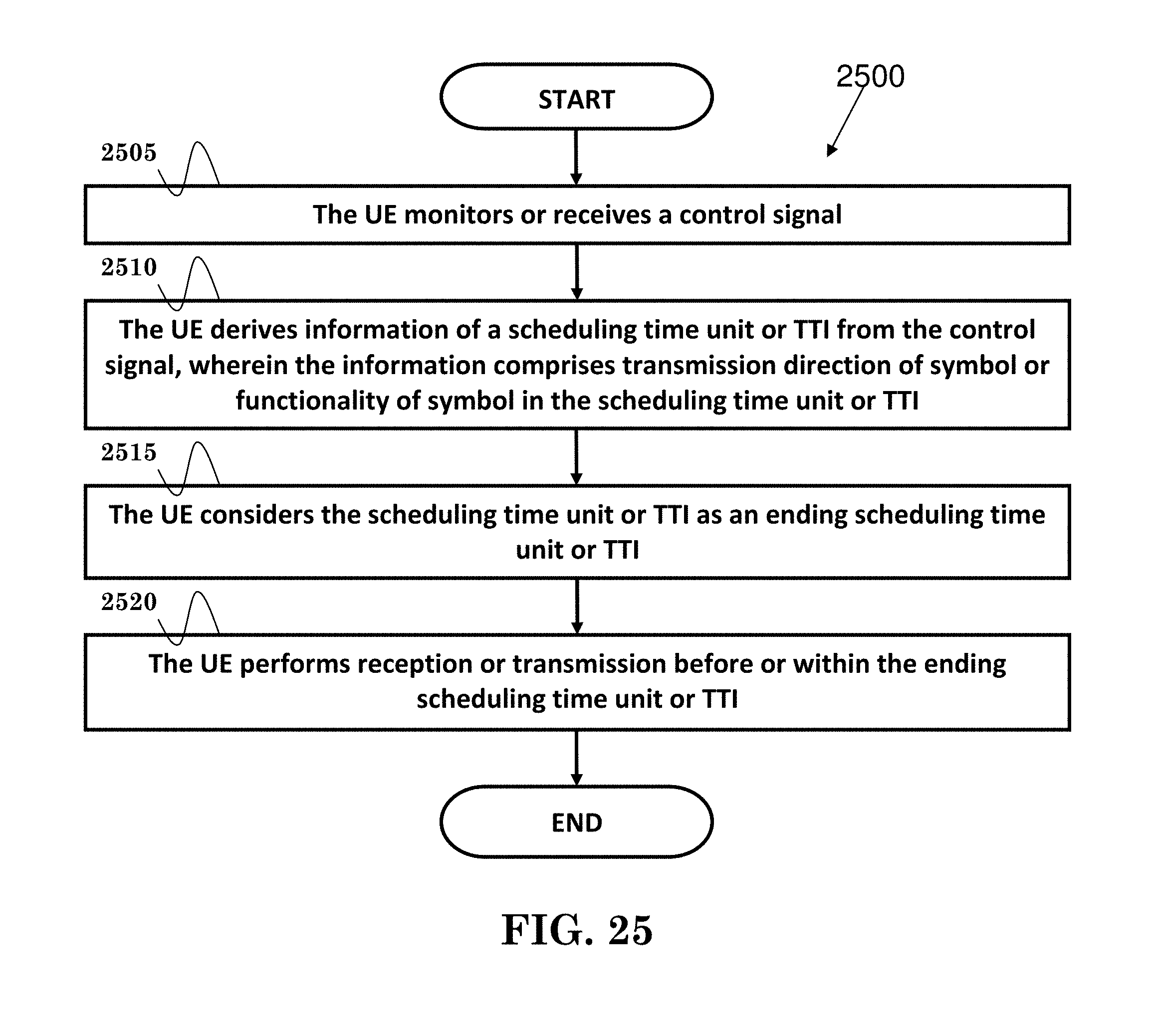
P00001

P00002
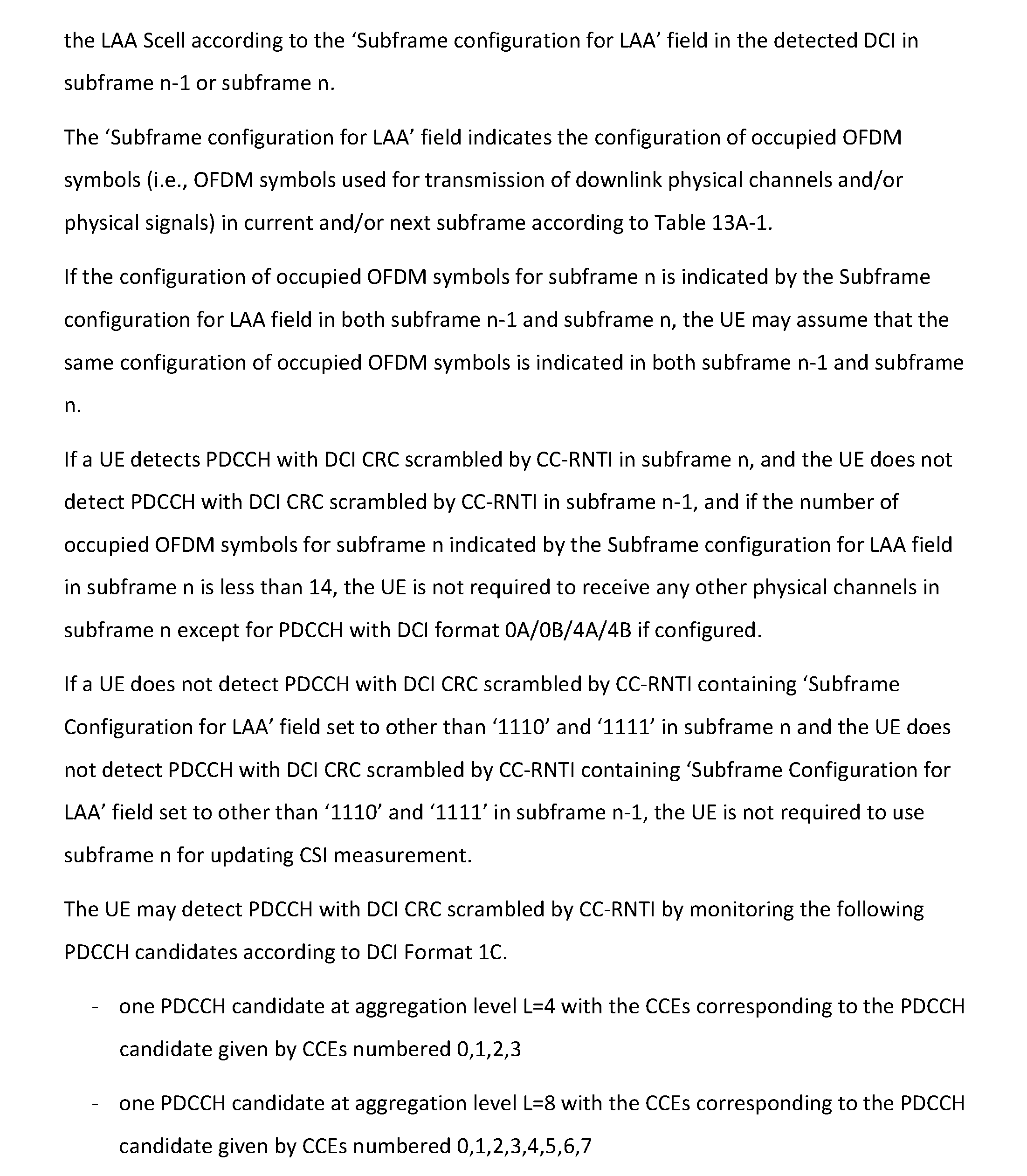
P00003

P00004

P00005
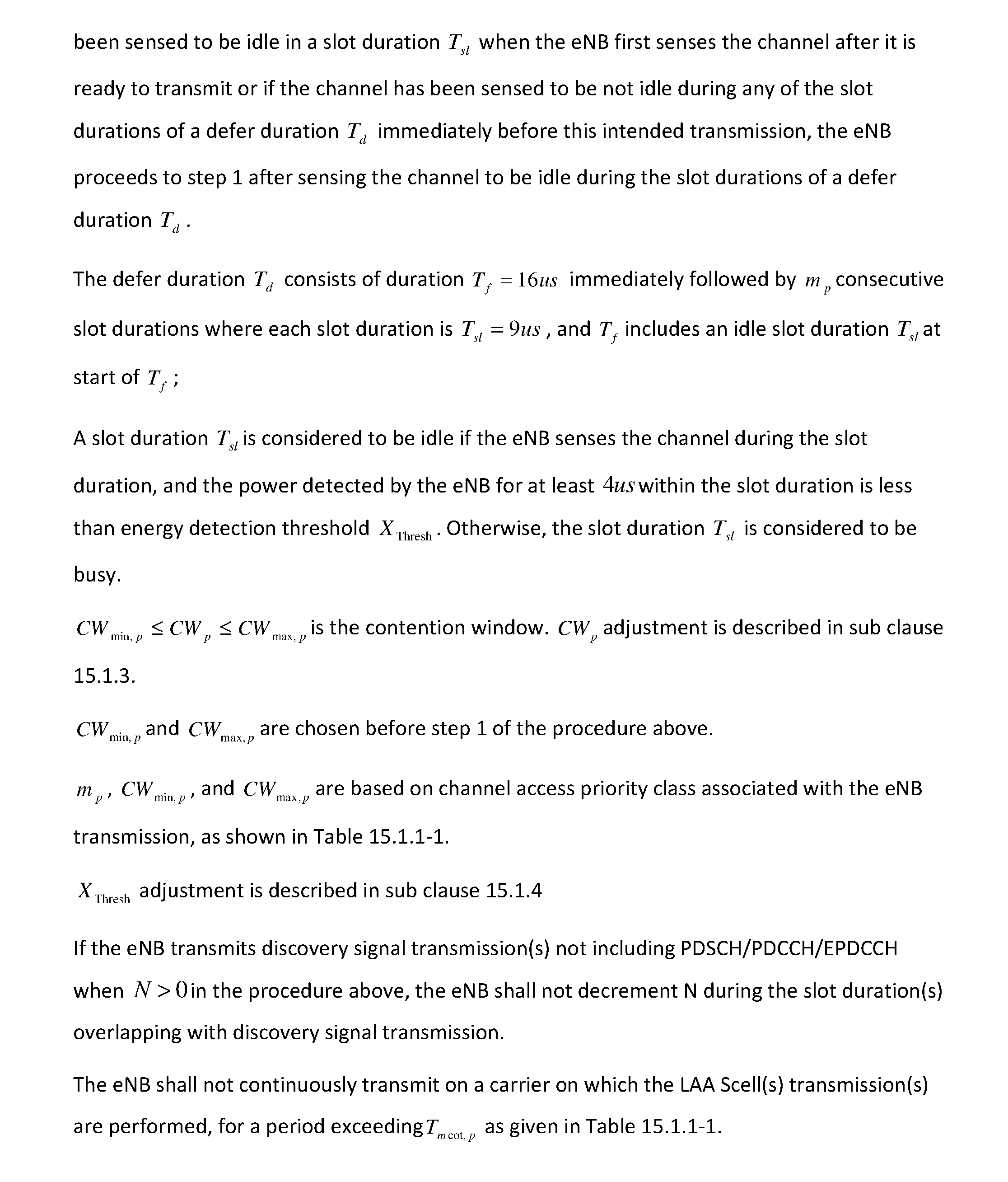
P00006
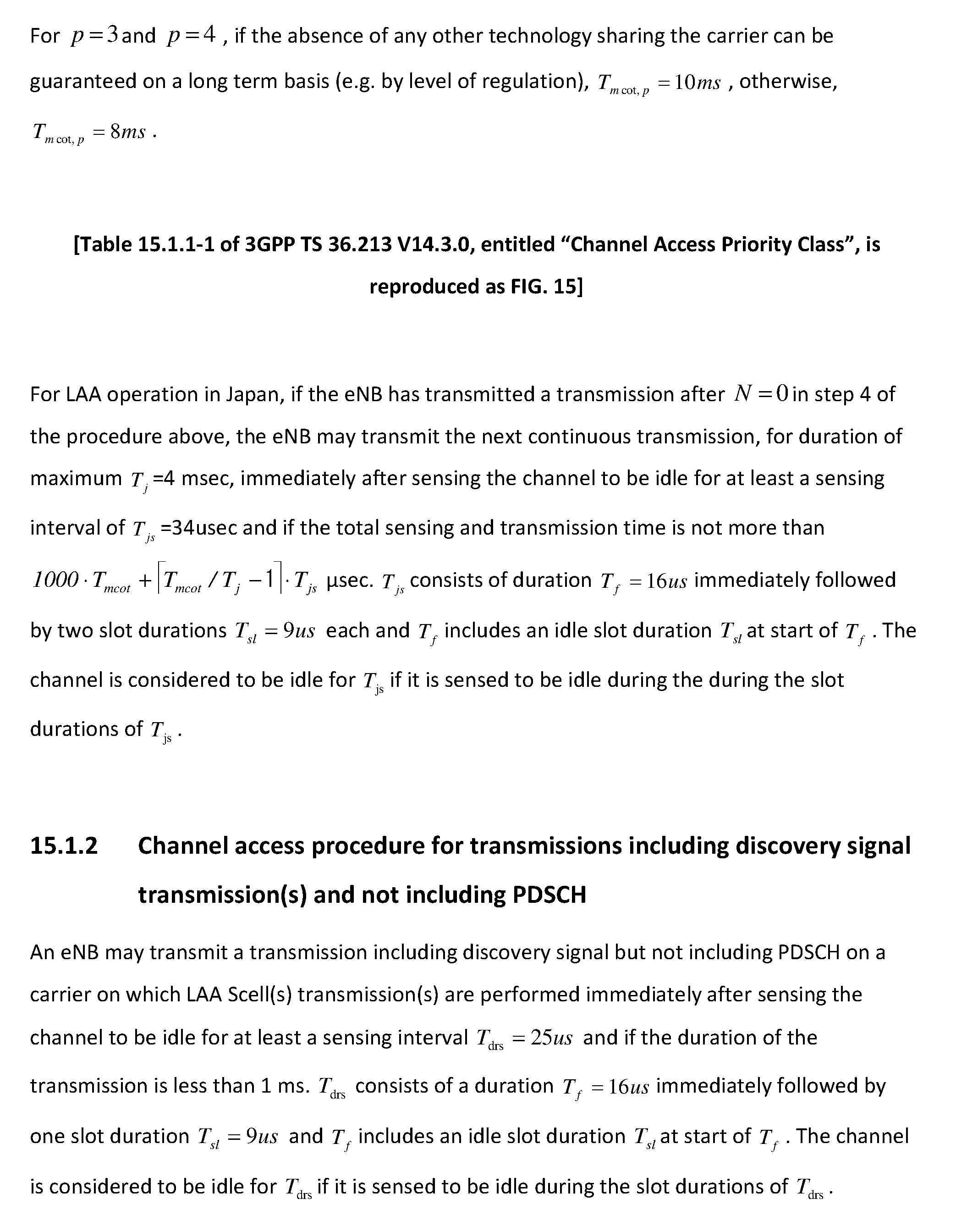
P00007
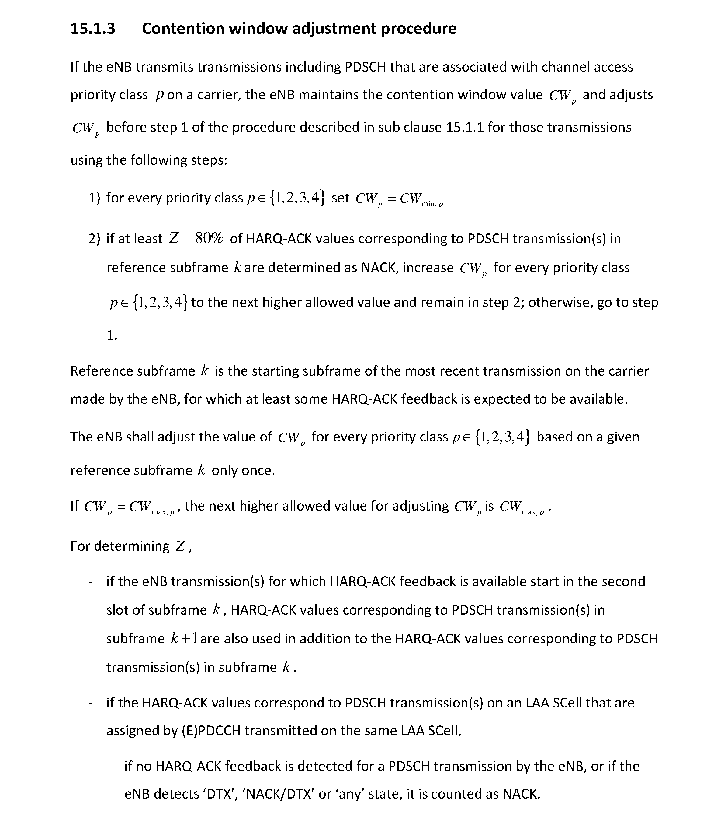
P00008
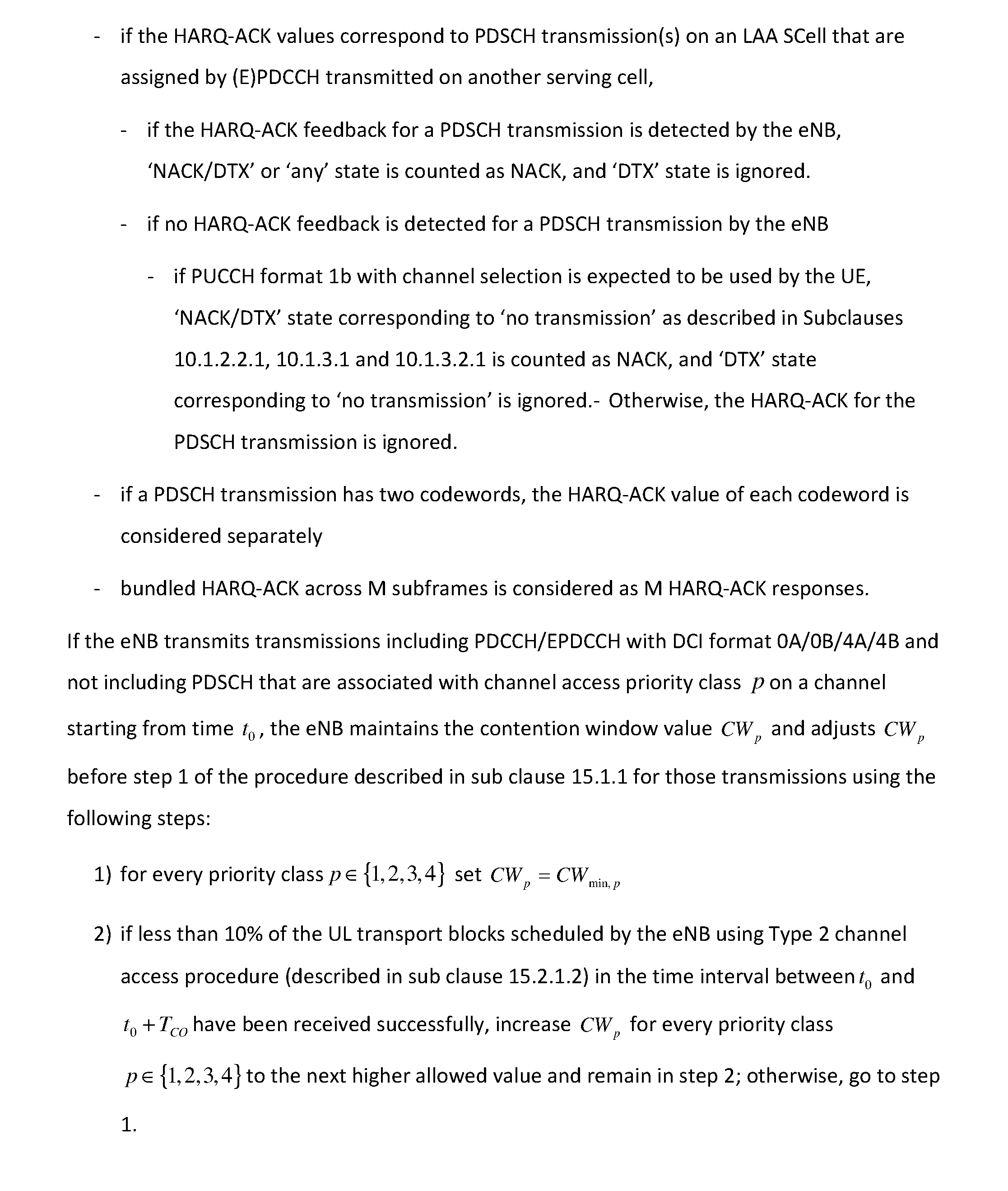
P00009
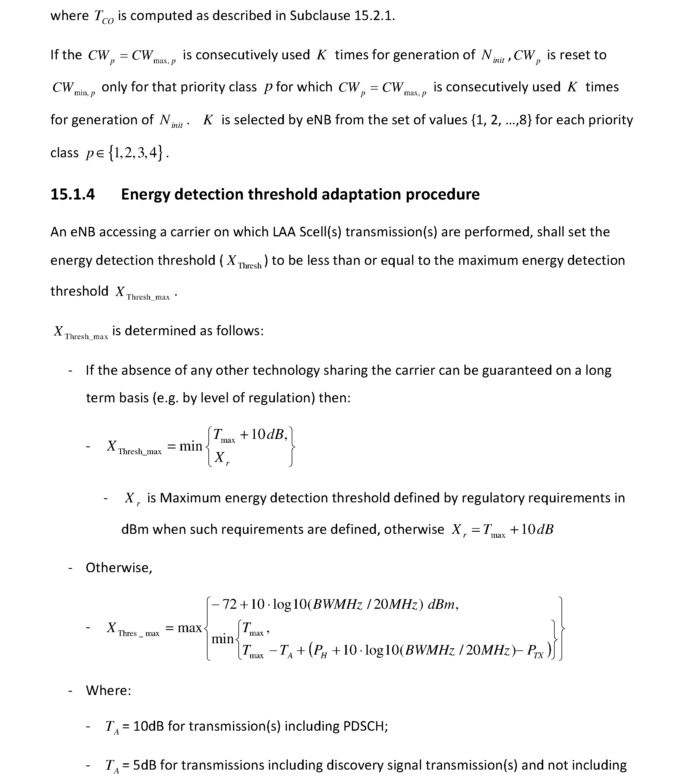
P00010
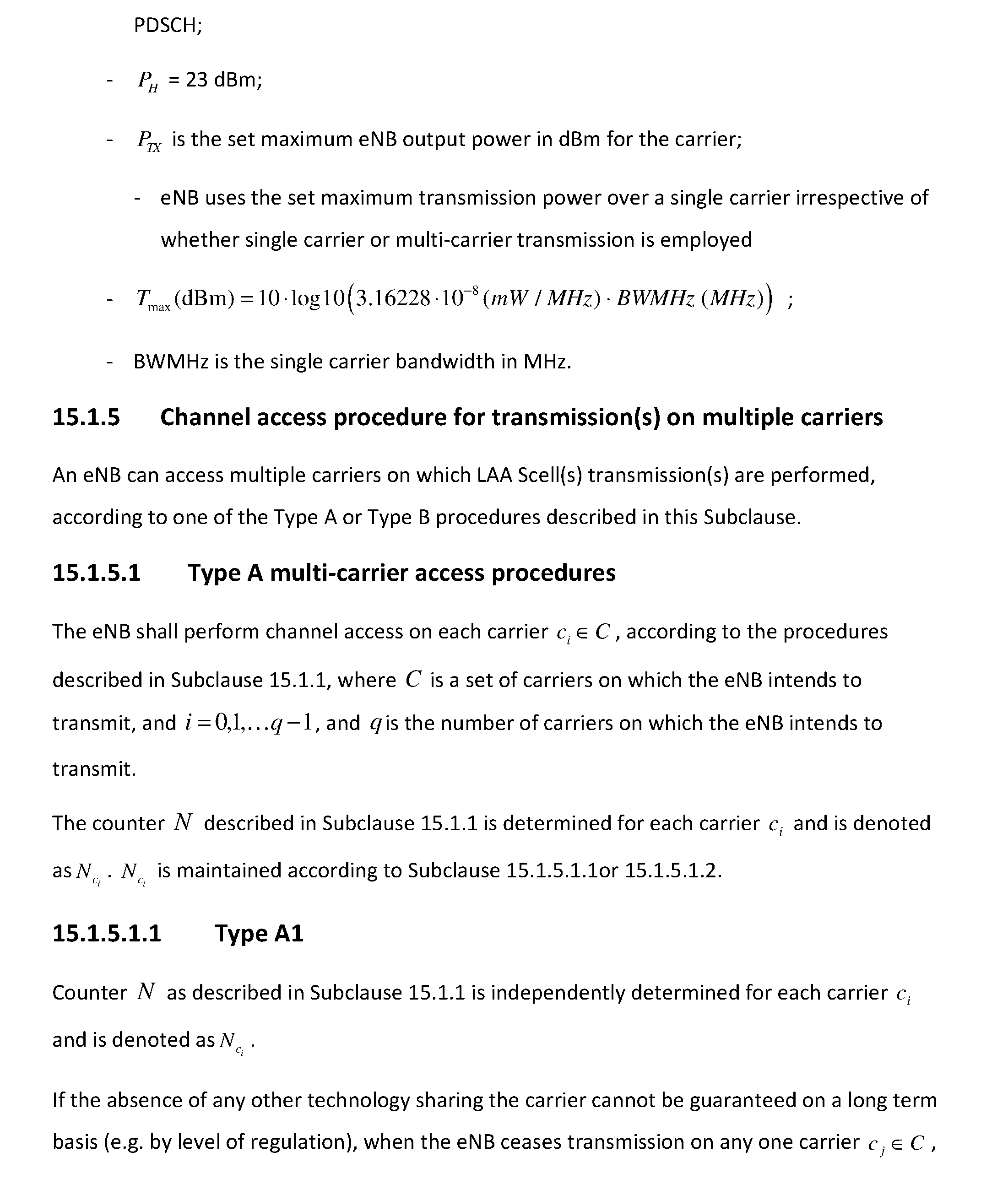
P00011
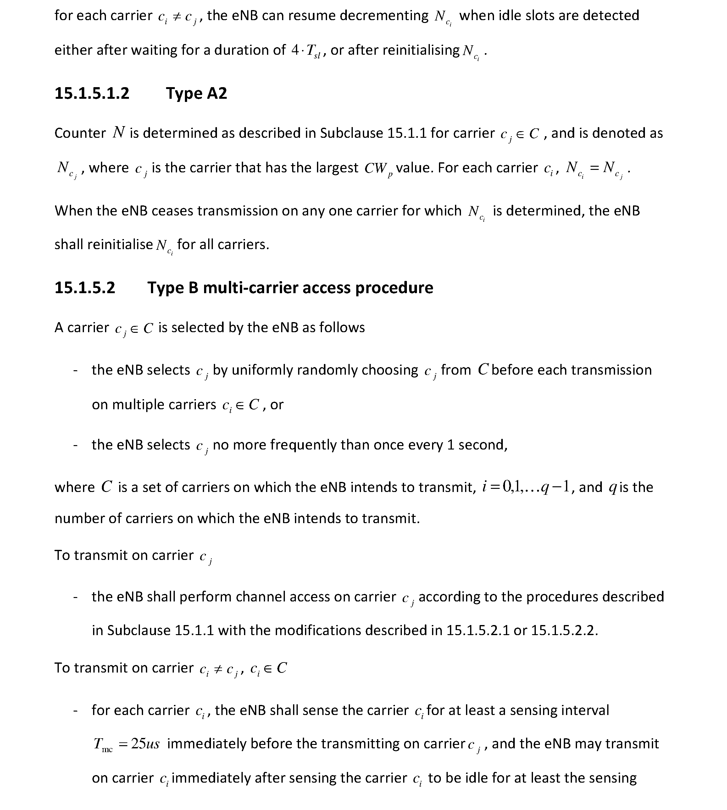
P00012
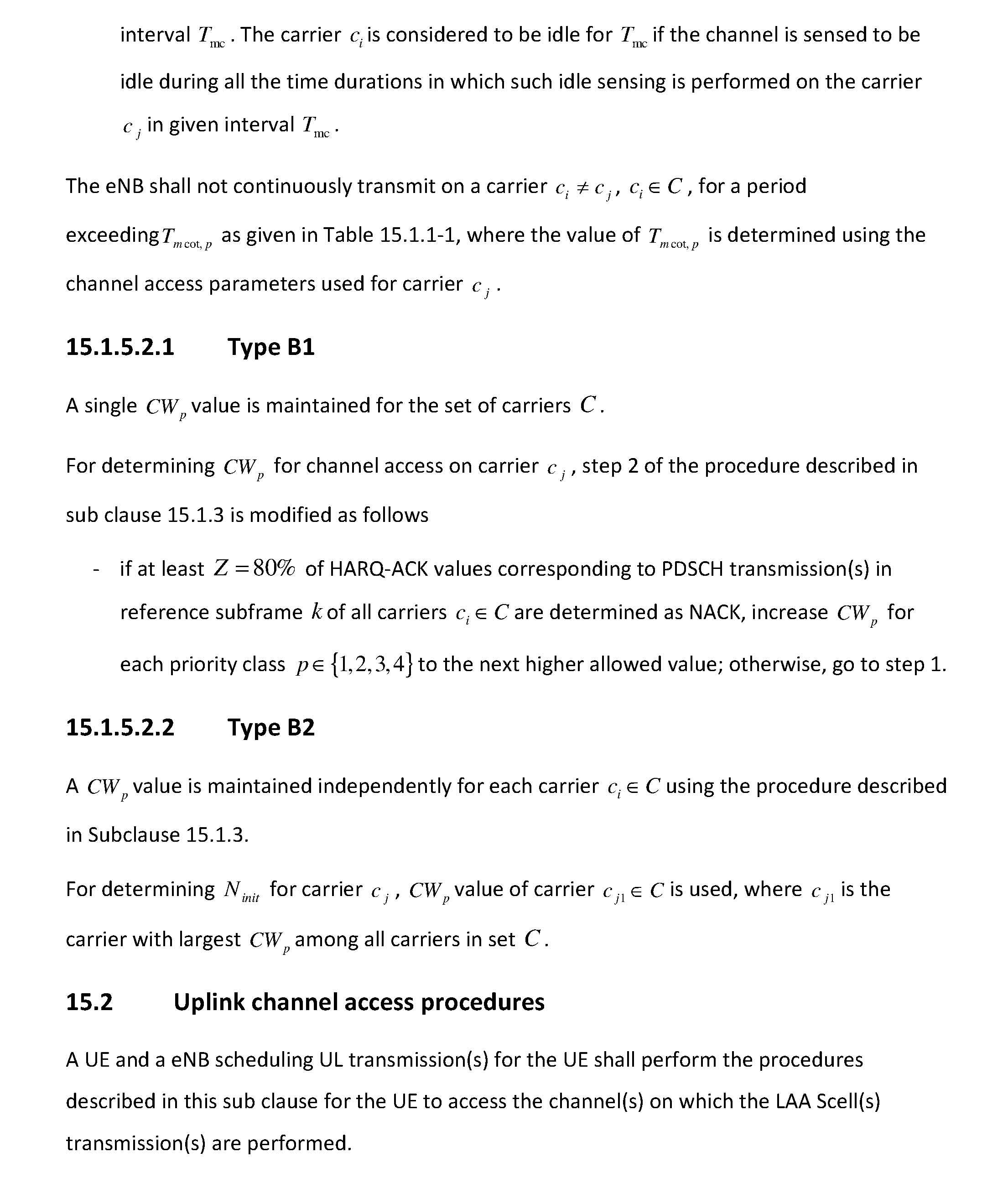
P00013
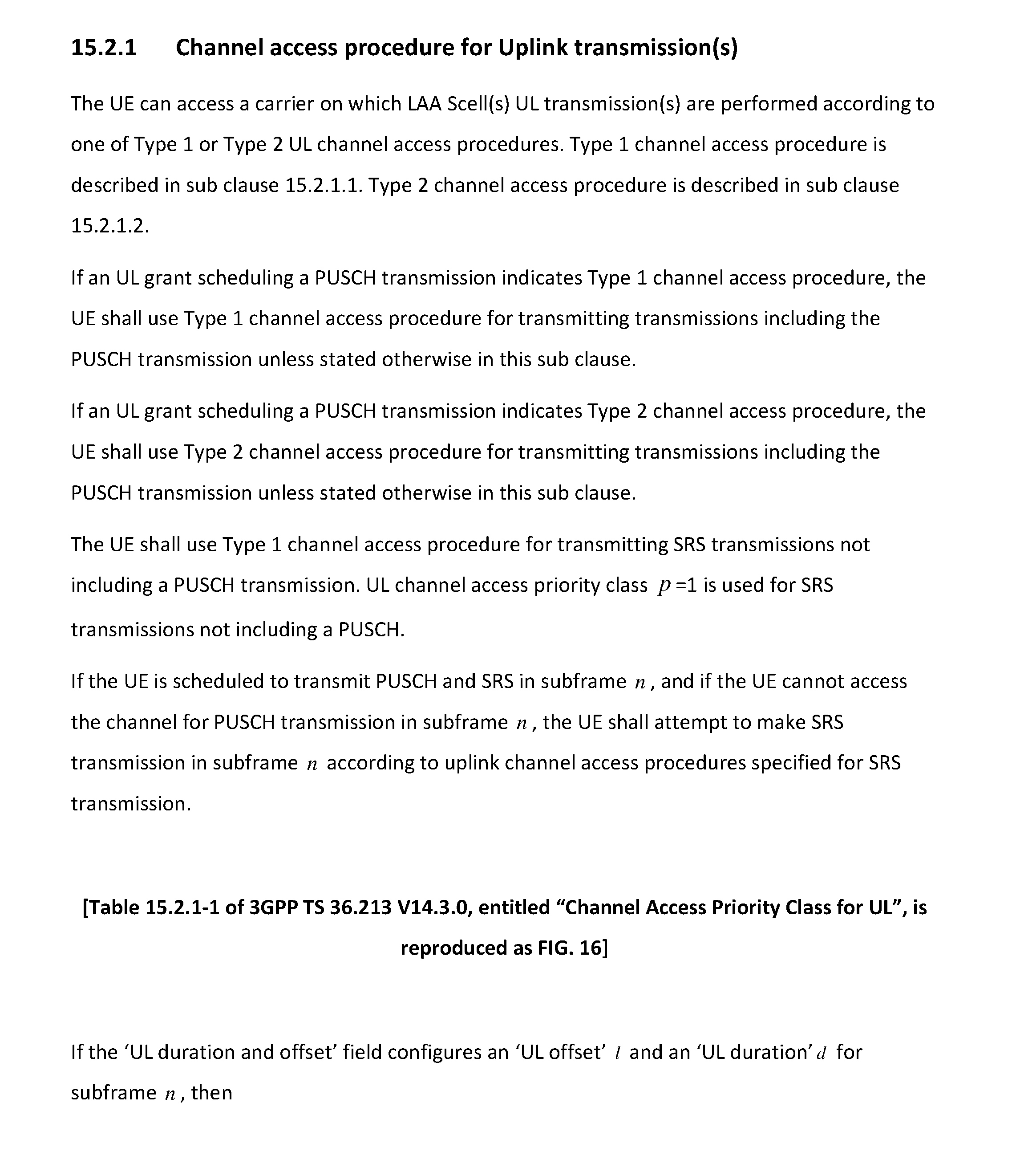
P00014
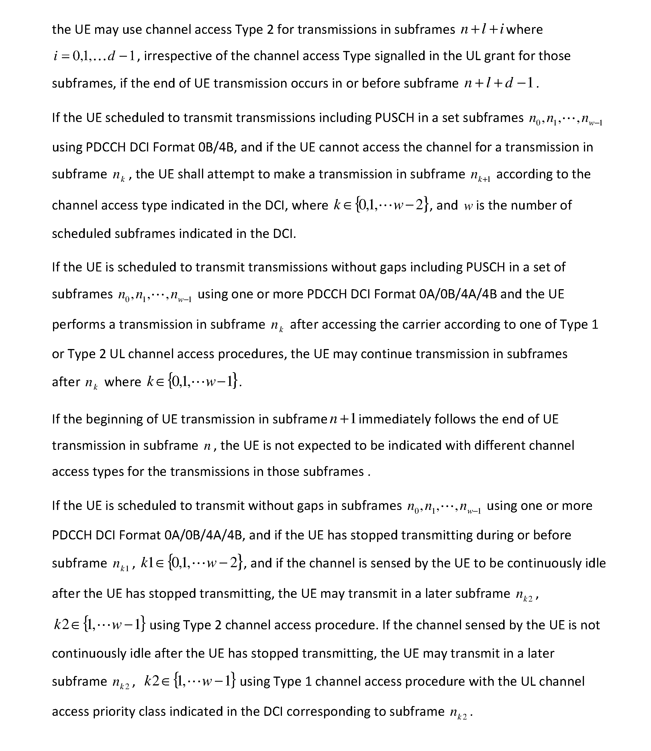
P00015
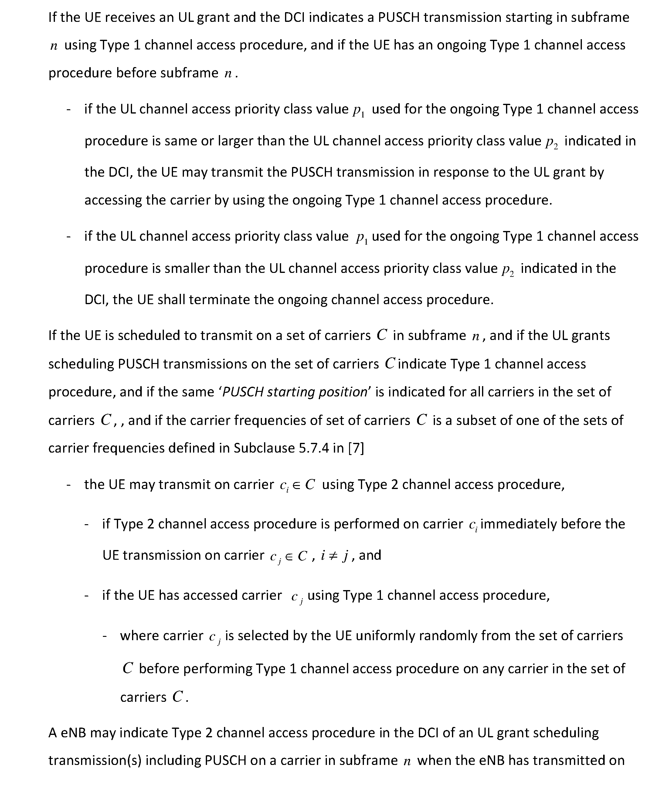
P00016

P00017
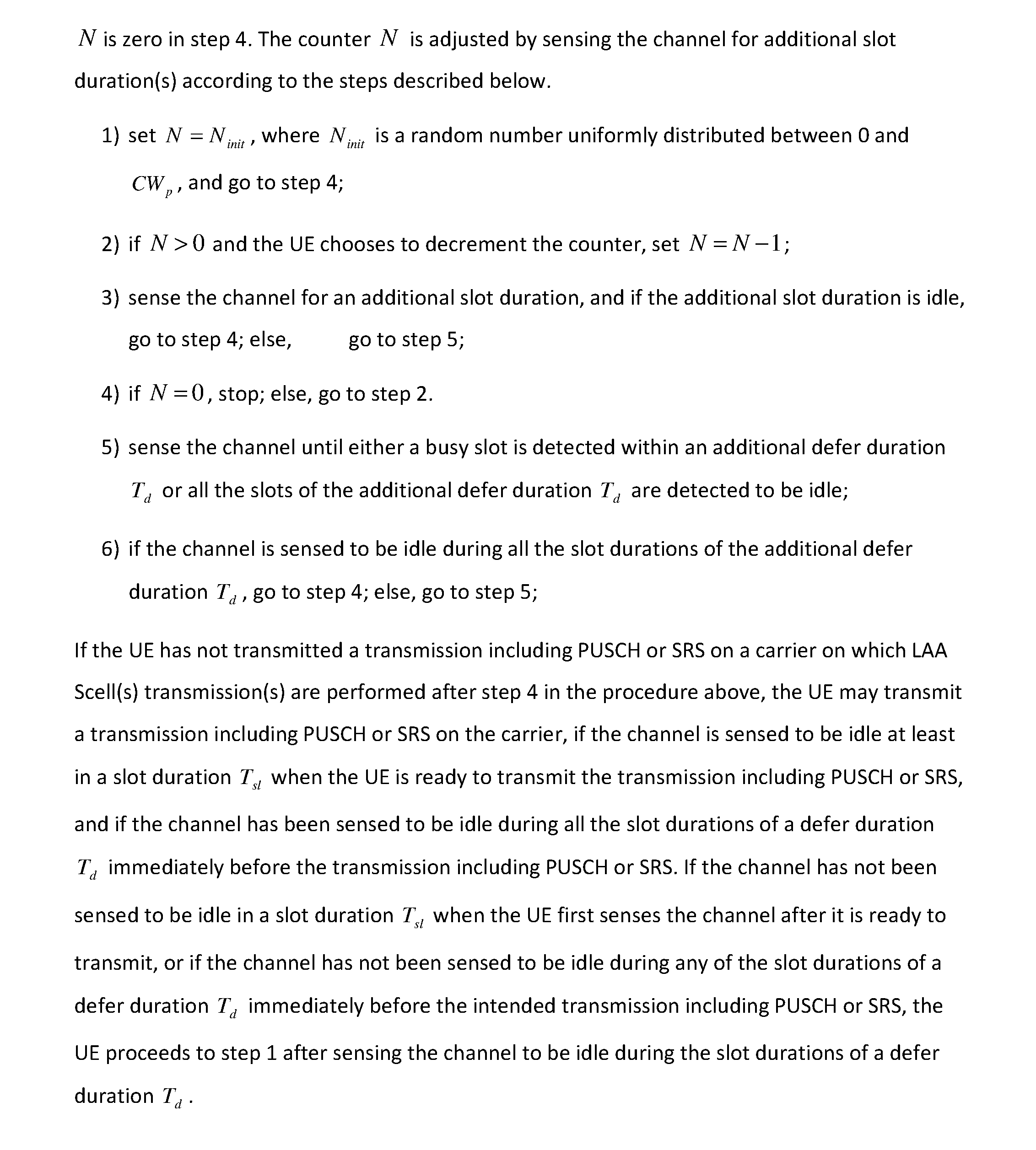
P00018
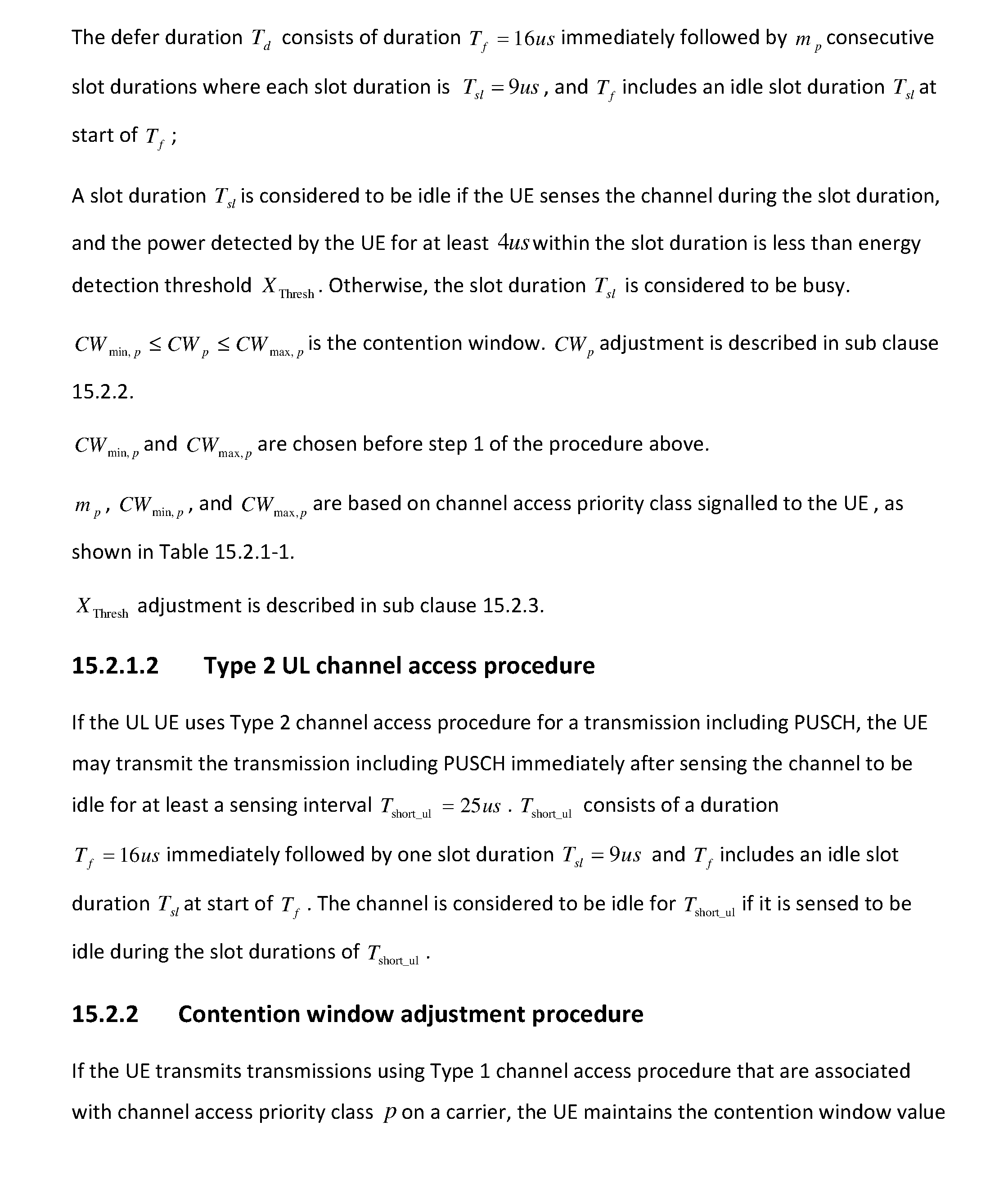
P00019
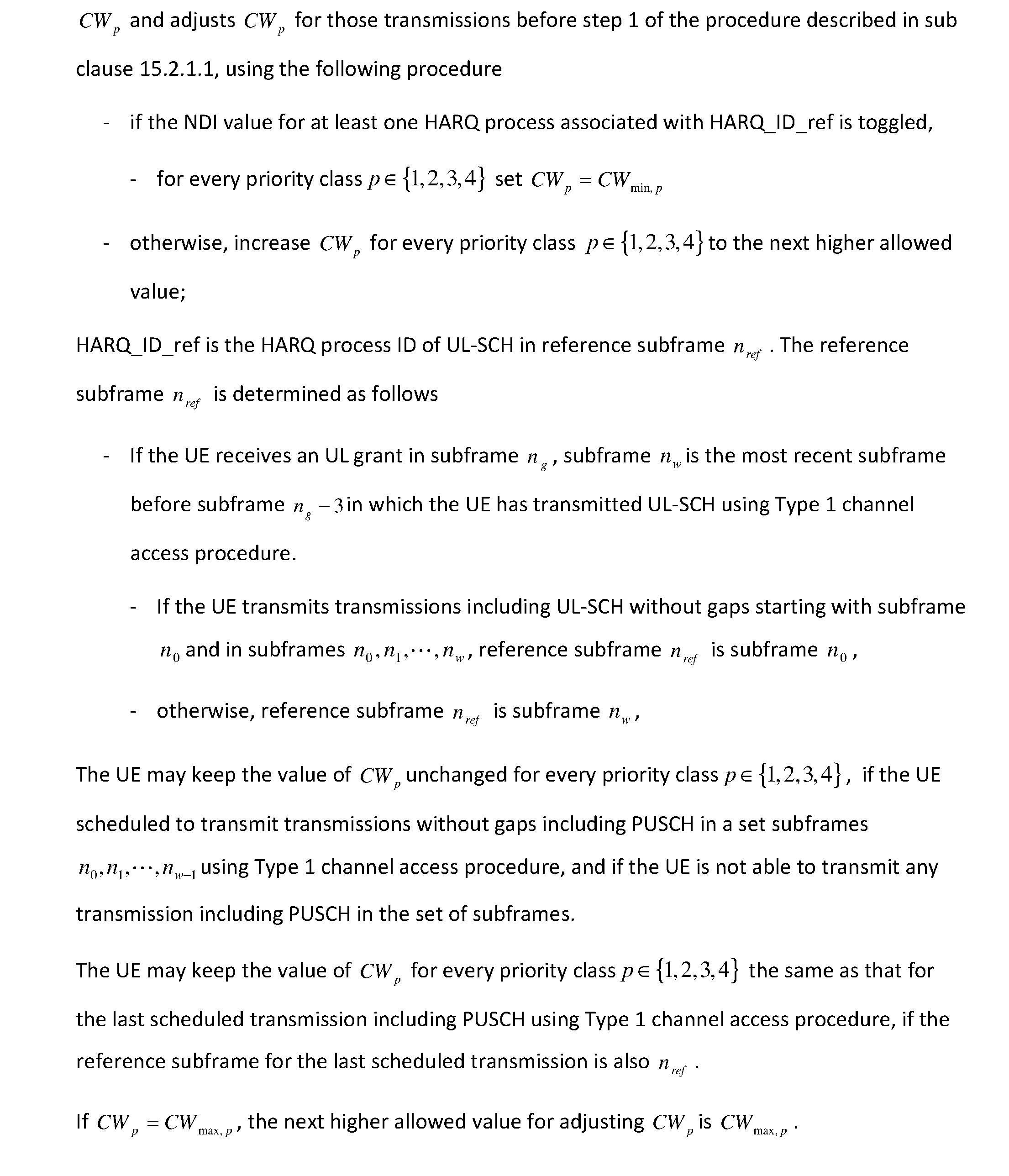
P00020

P00021

P00022

P00023

P00024

P00025
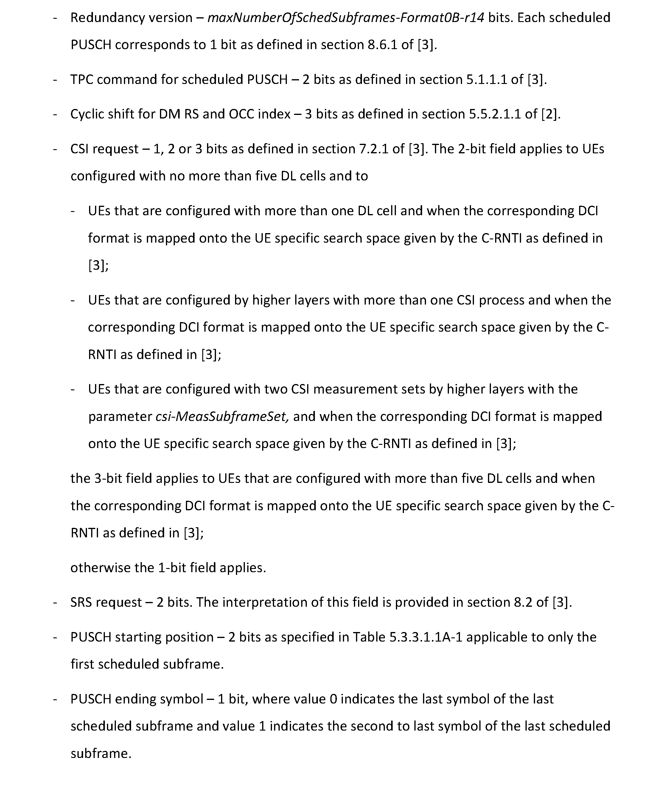
P00026

P00027
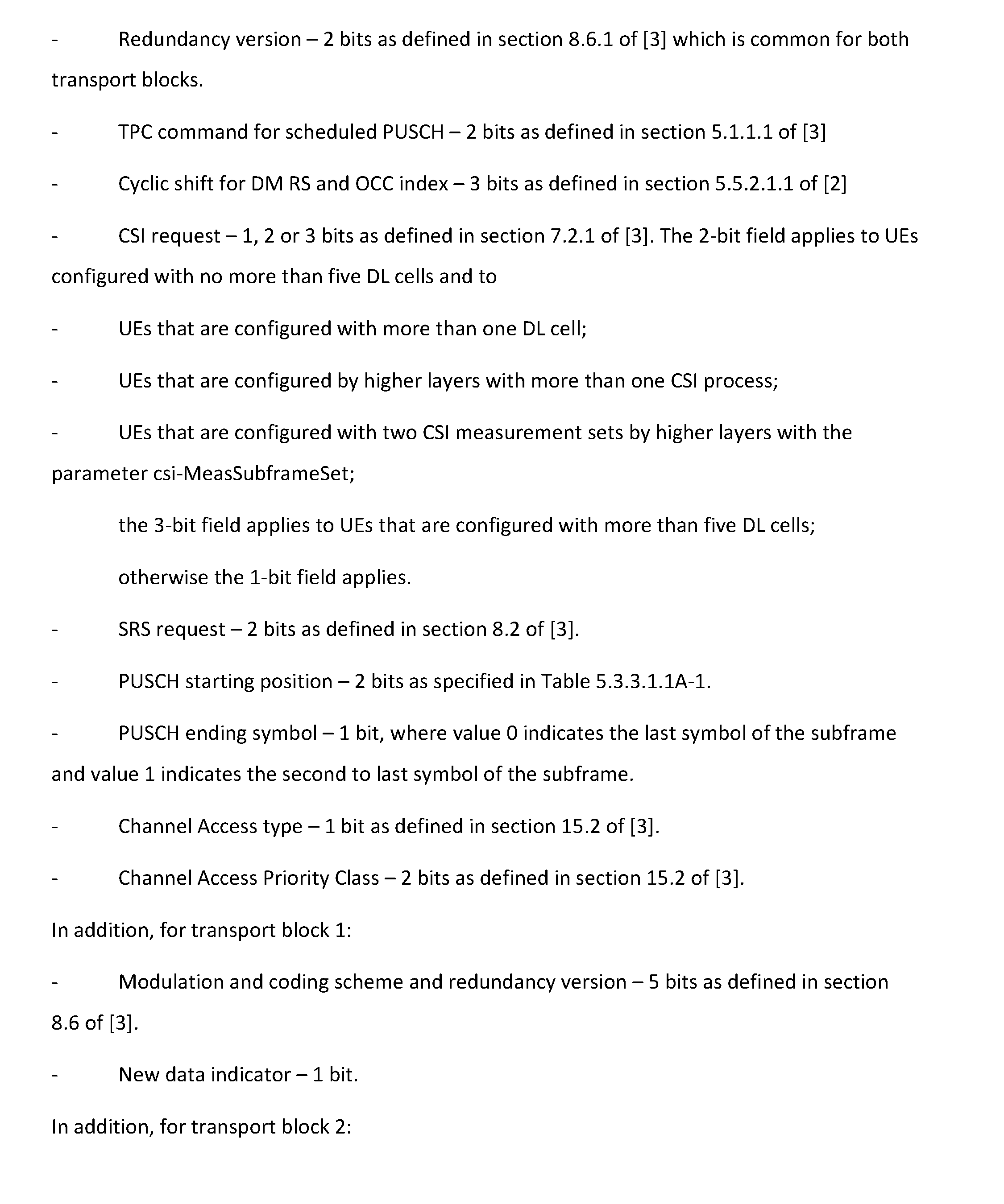
P00028
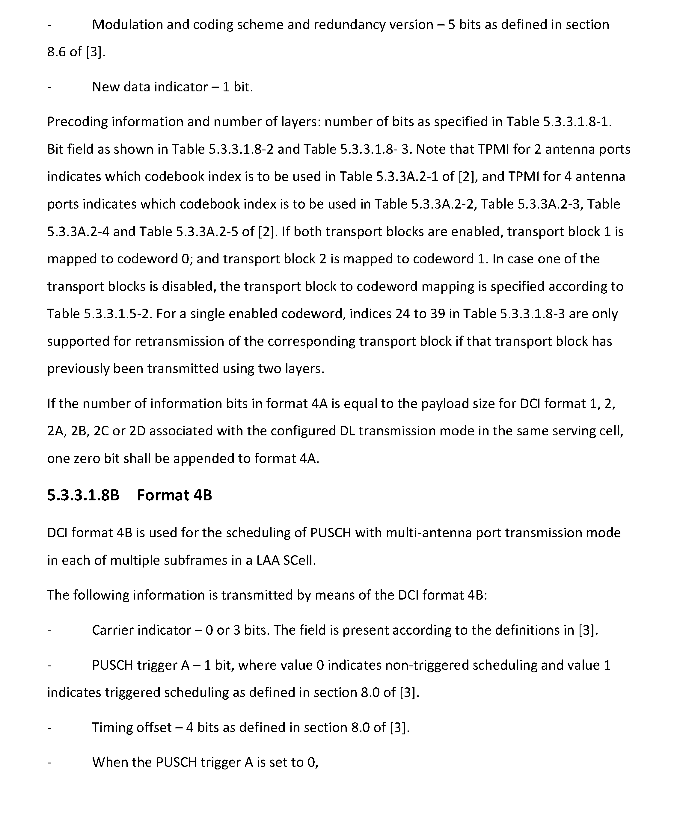
P00029
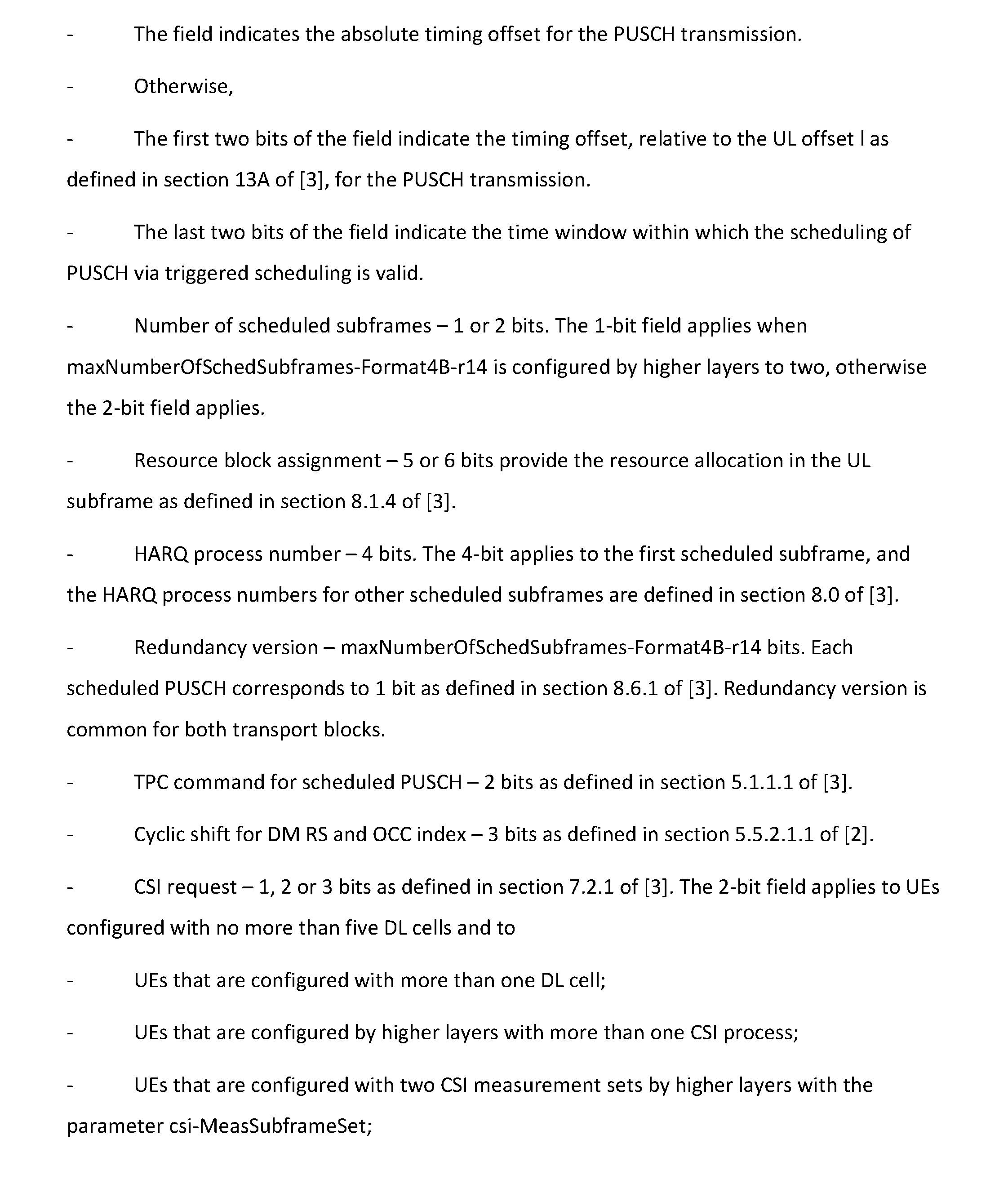
P00030

P00031
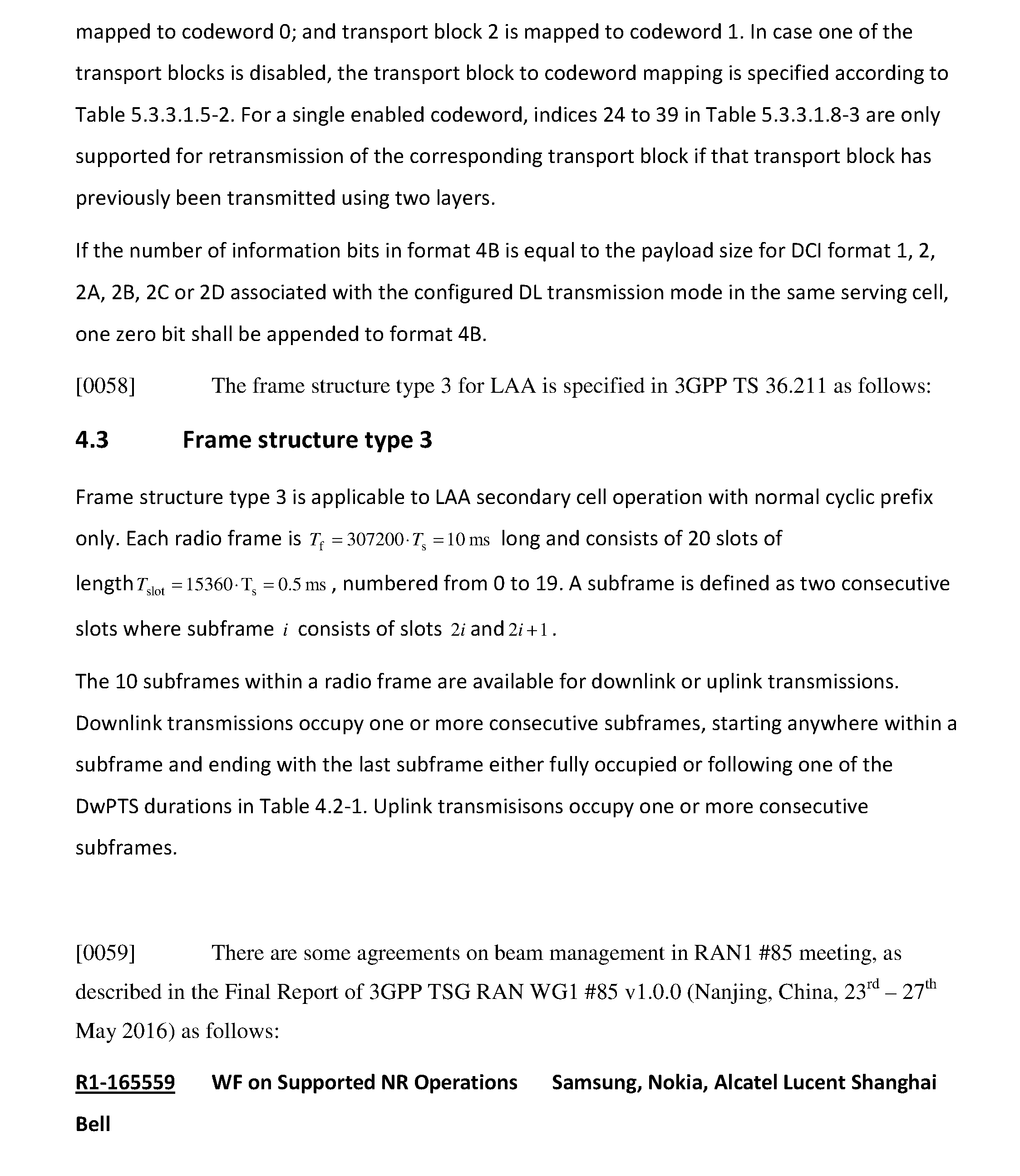
P00032
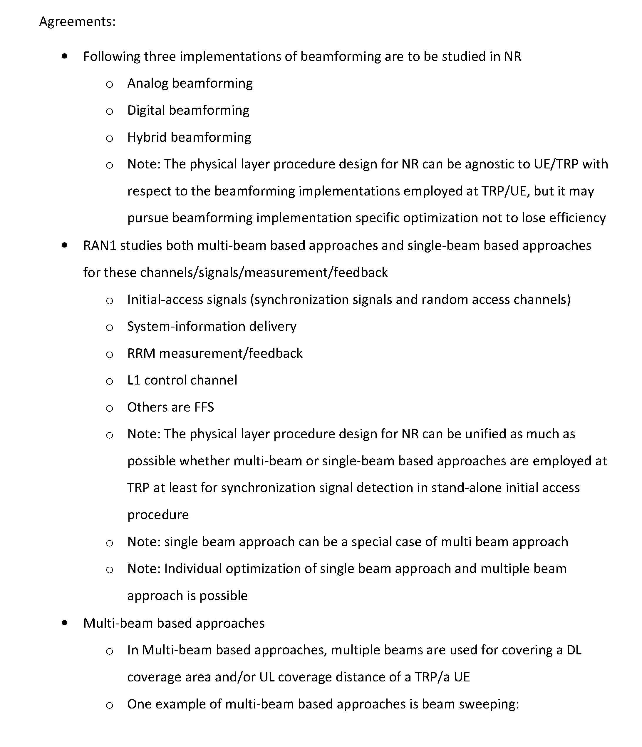
P00033
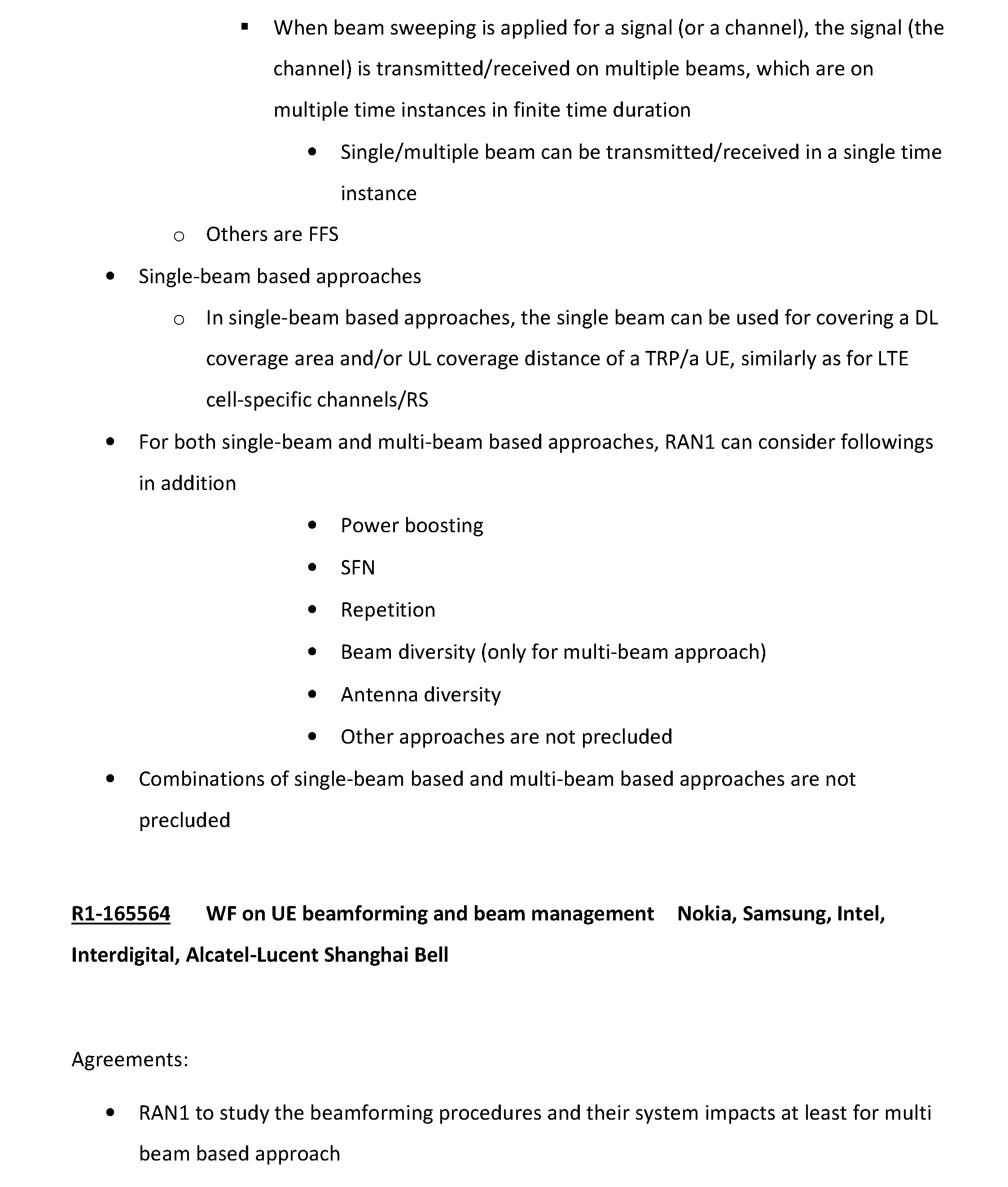
P00034

P00035
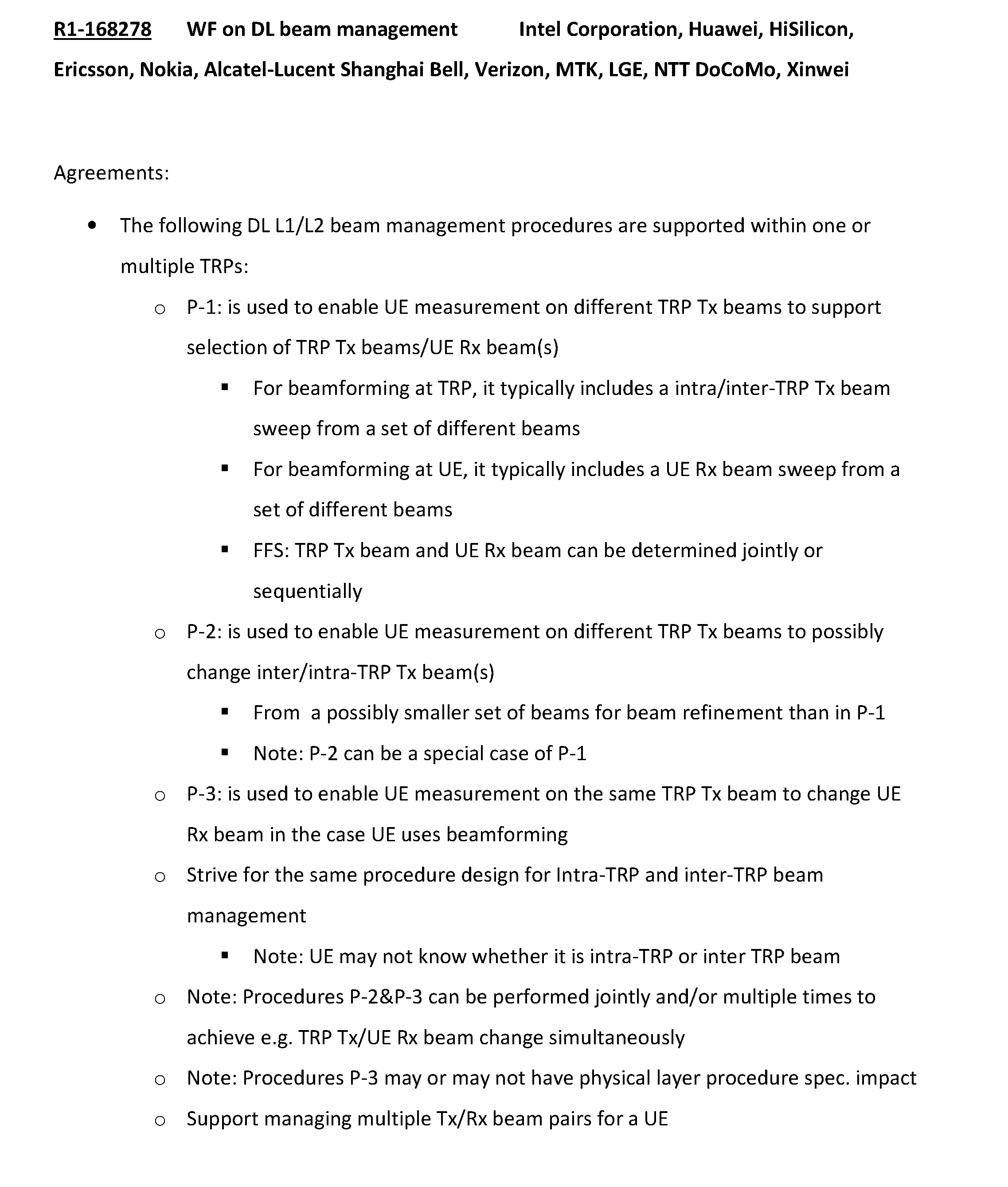
P00036
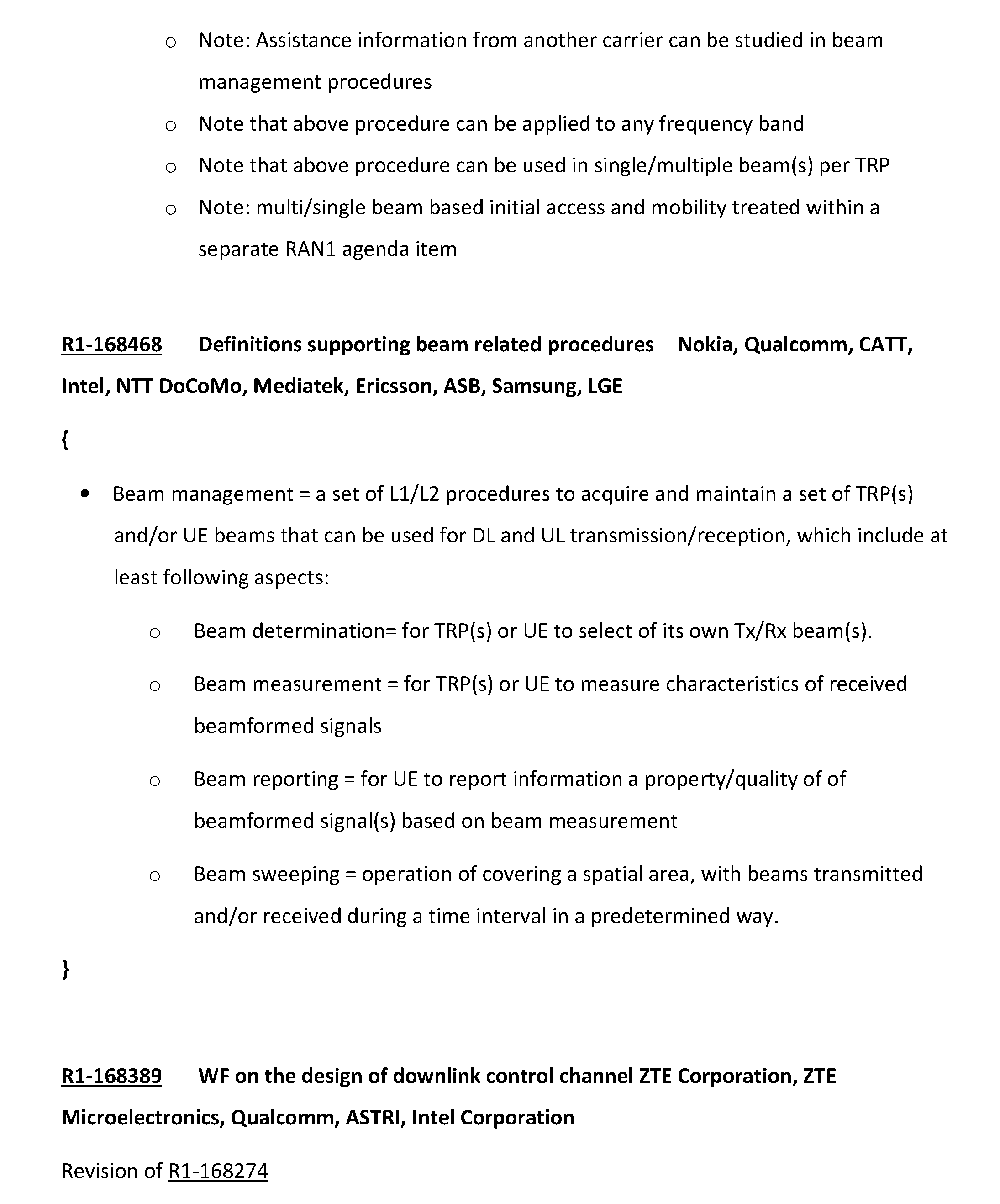
P00037
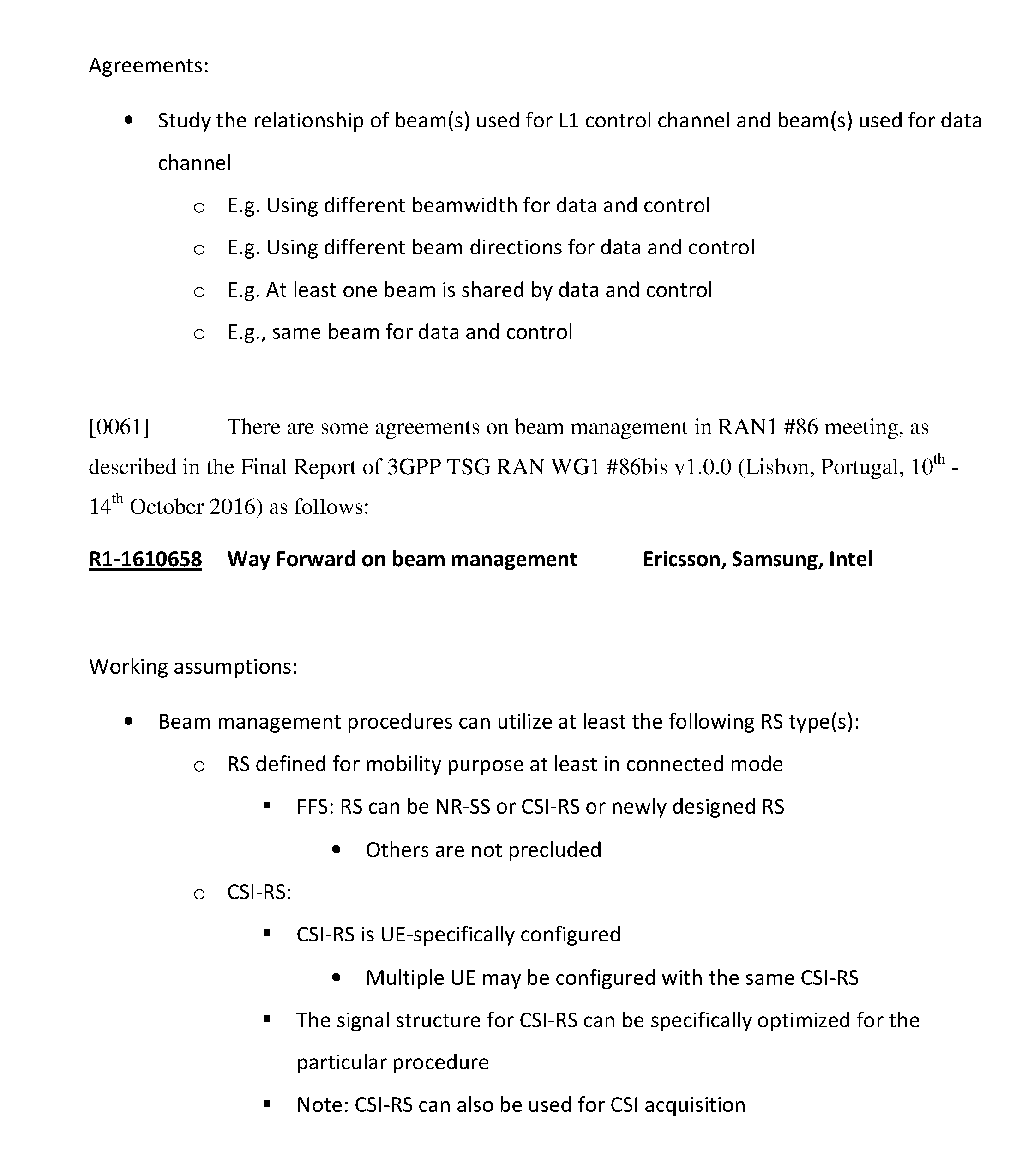
P00038

P00039
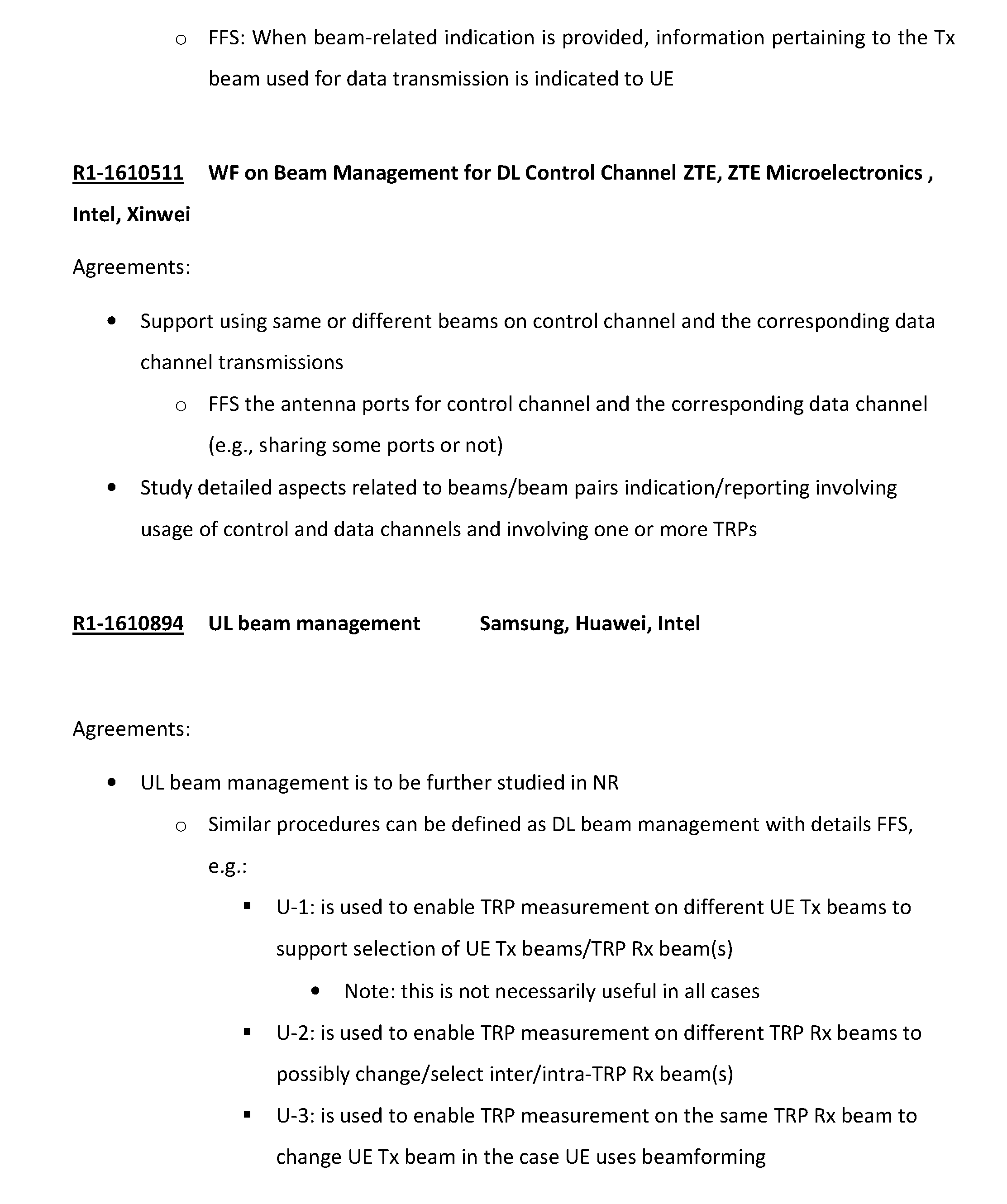
P00040
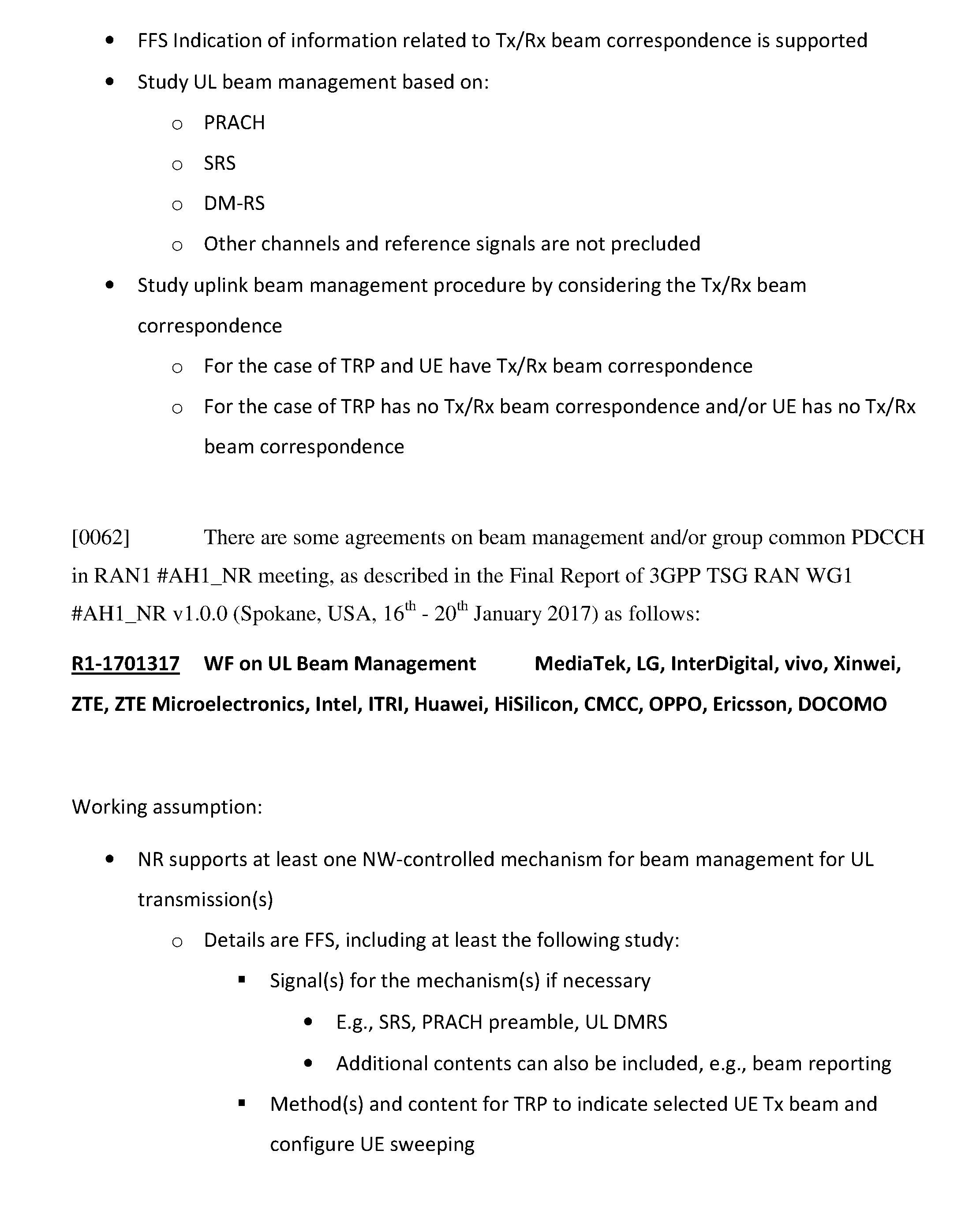
P00041
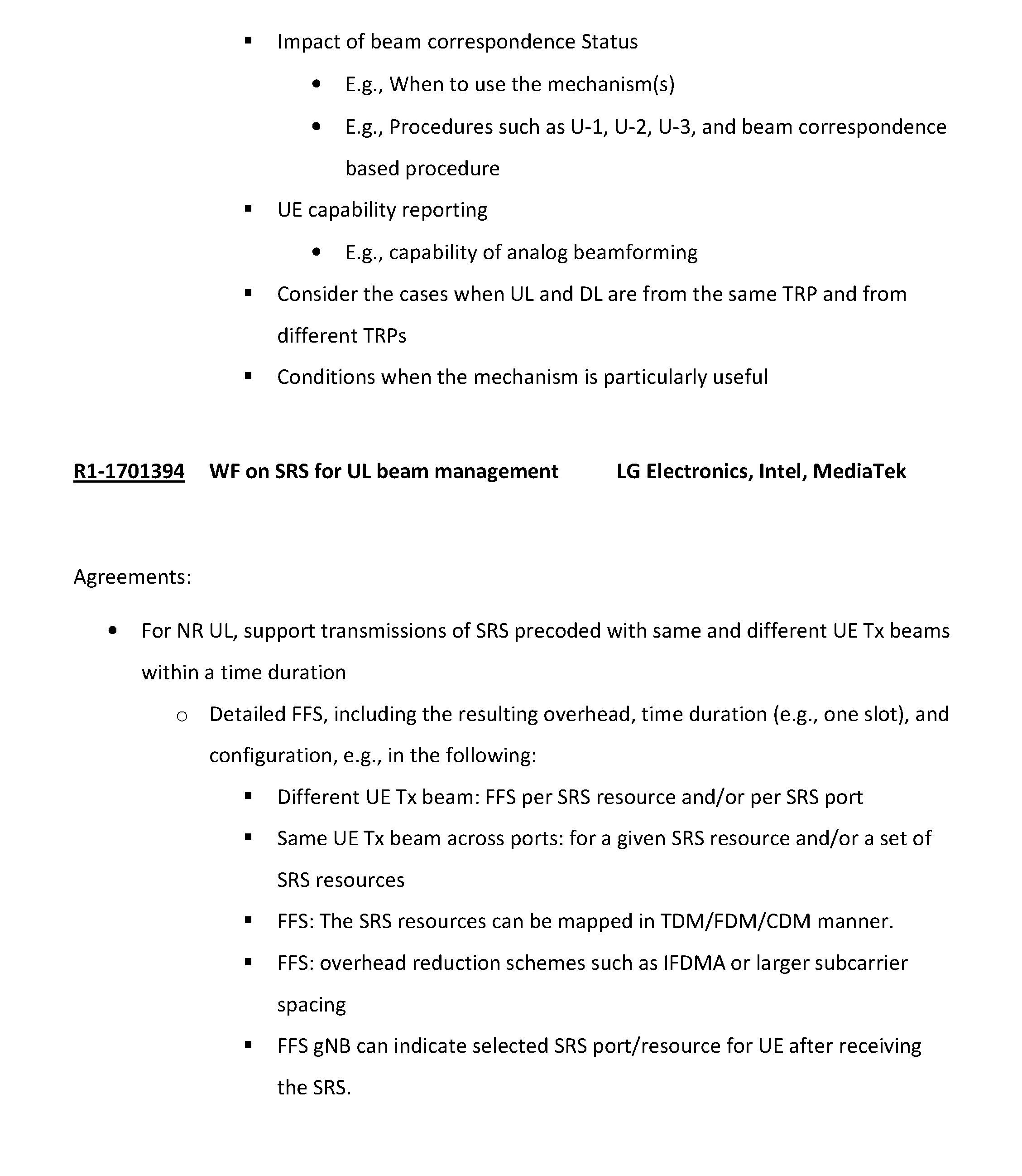
P00042

P00043
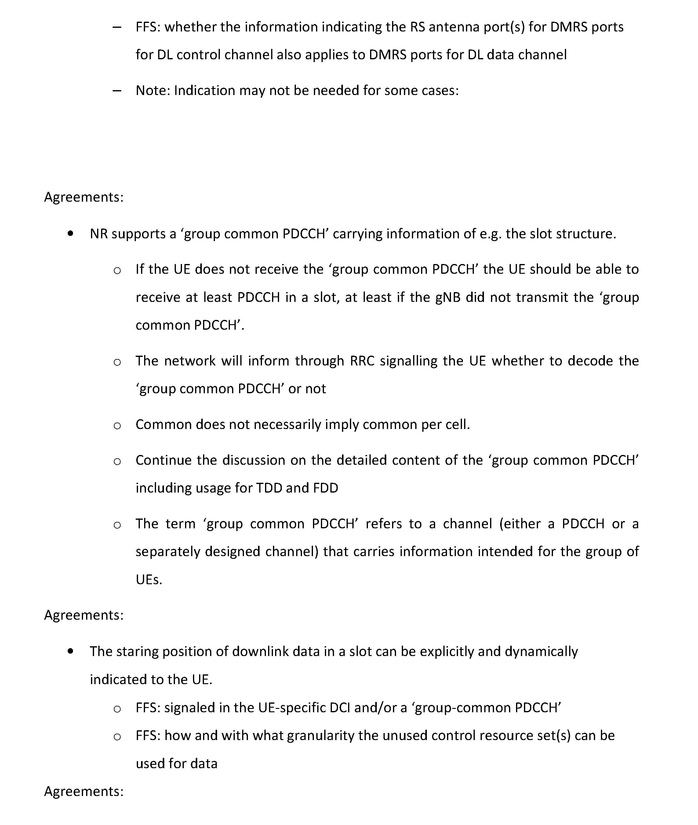
P00044
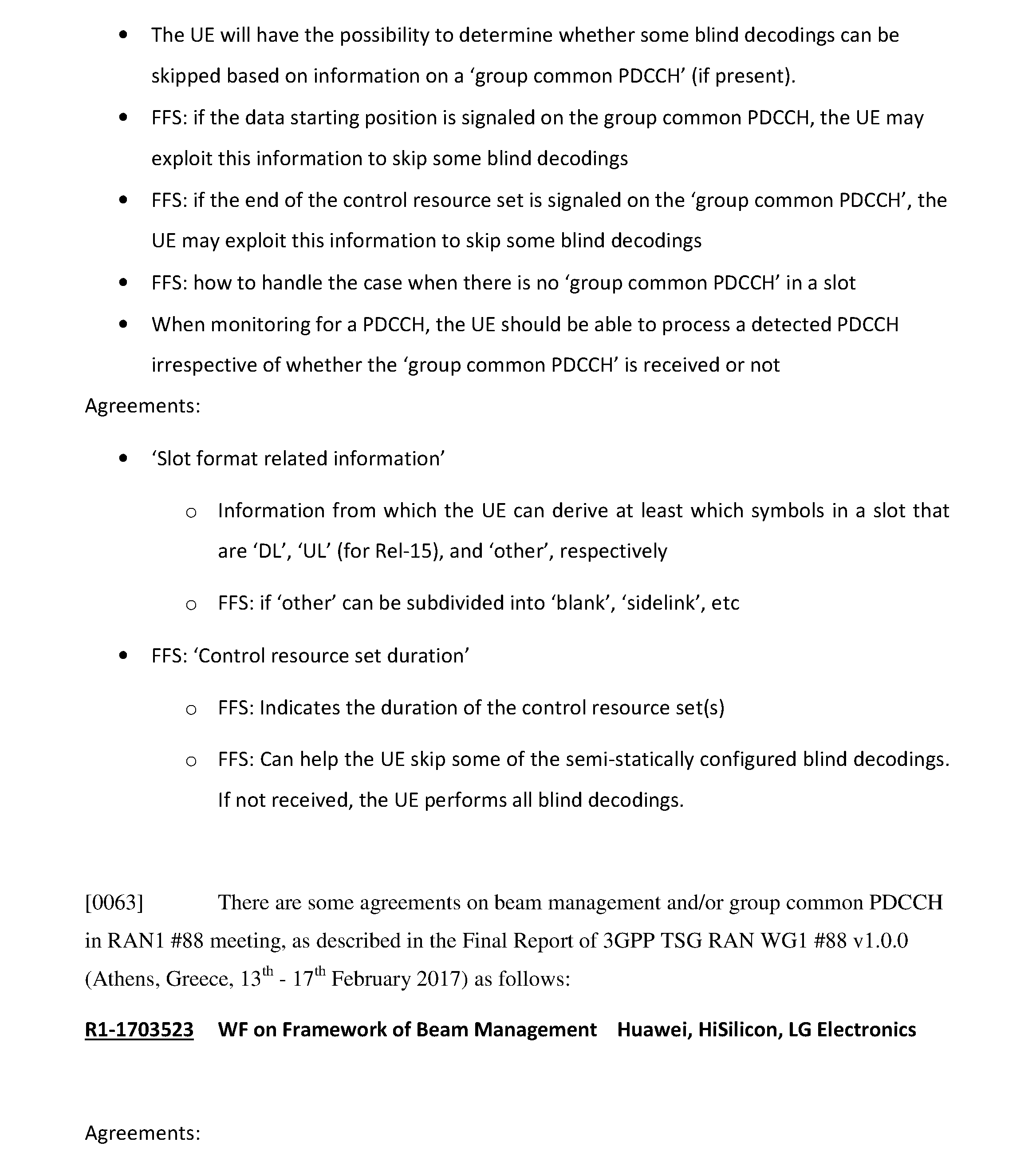
P00045
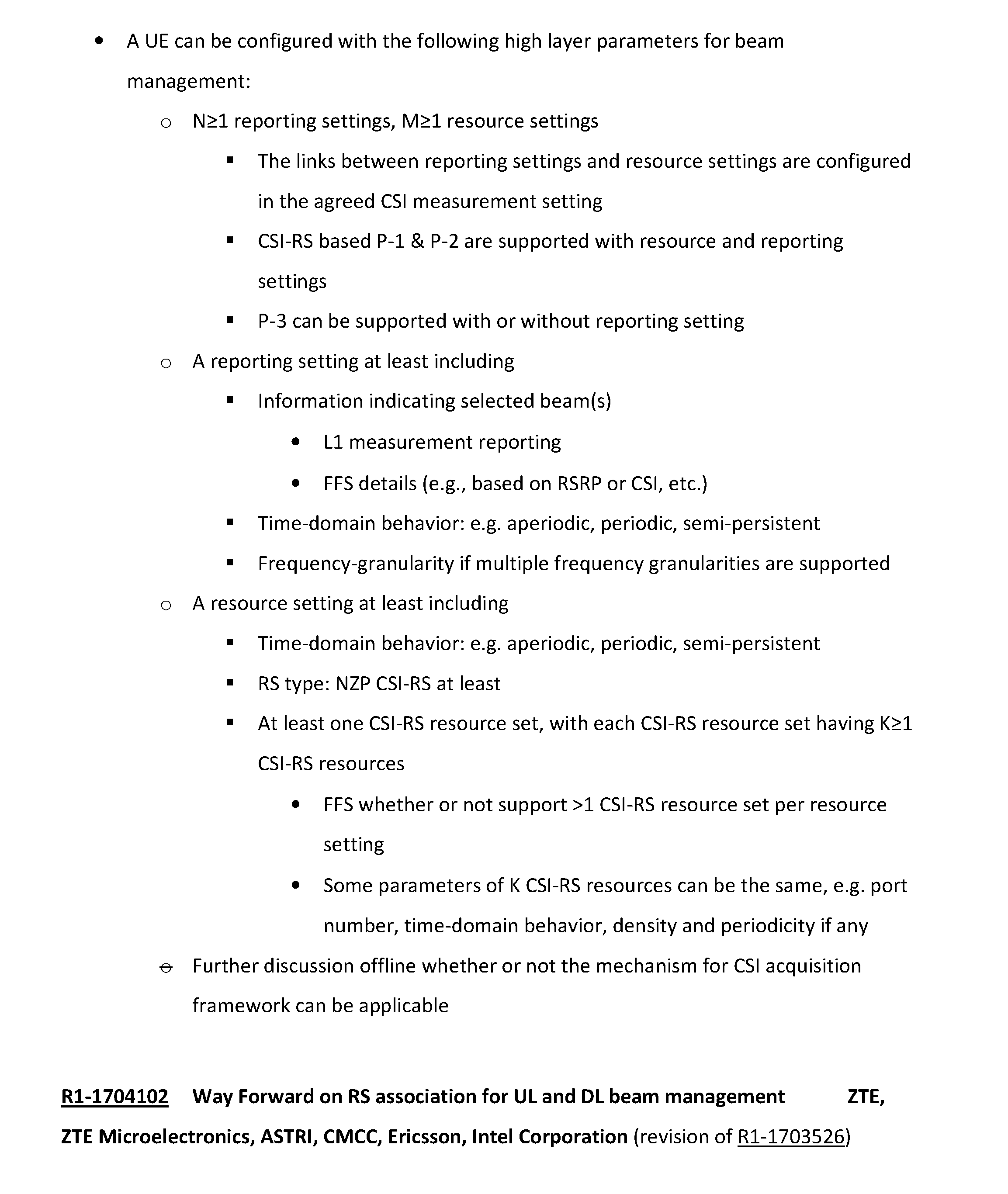
P00046
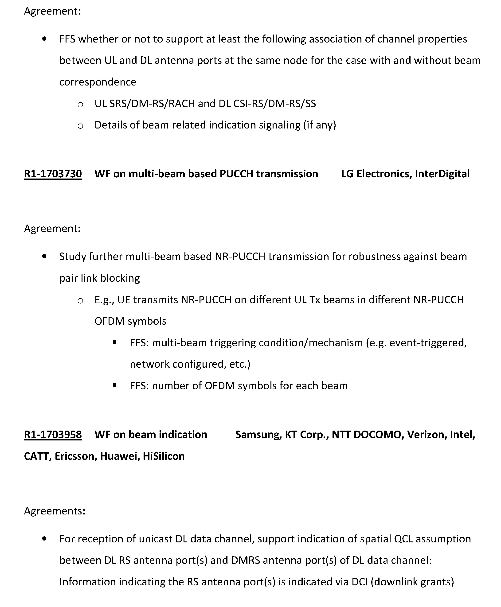
P00047
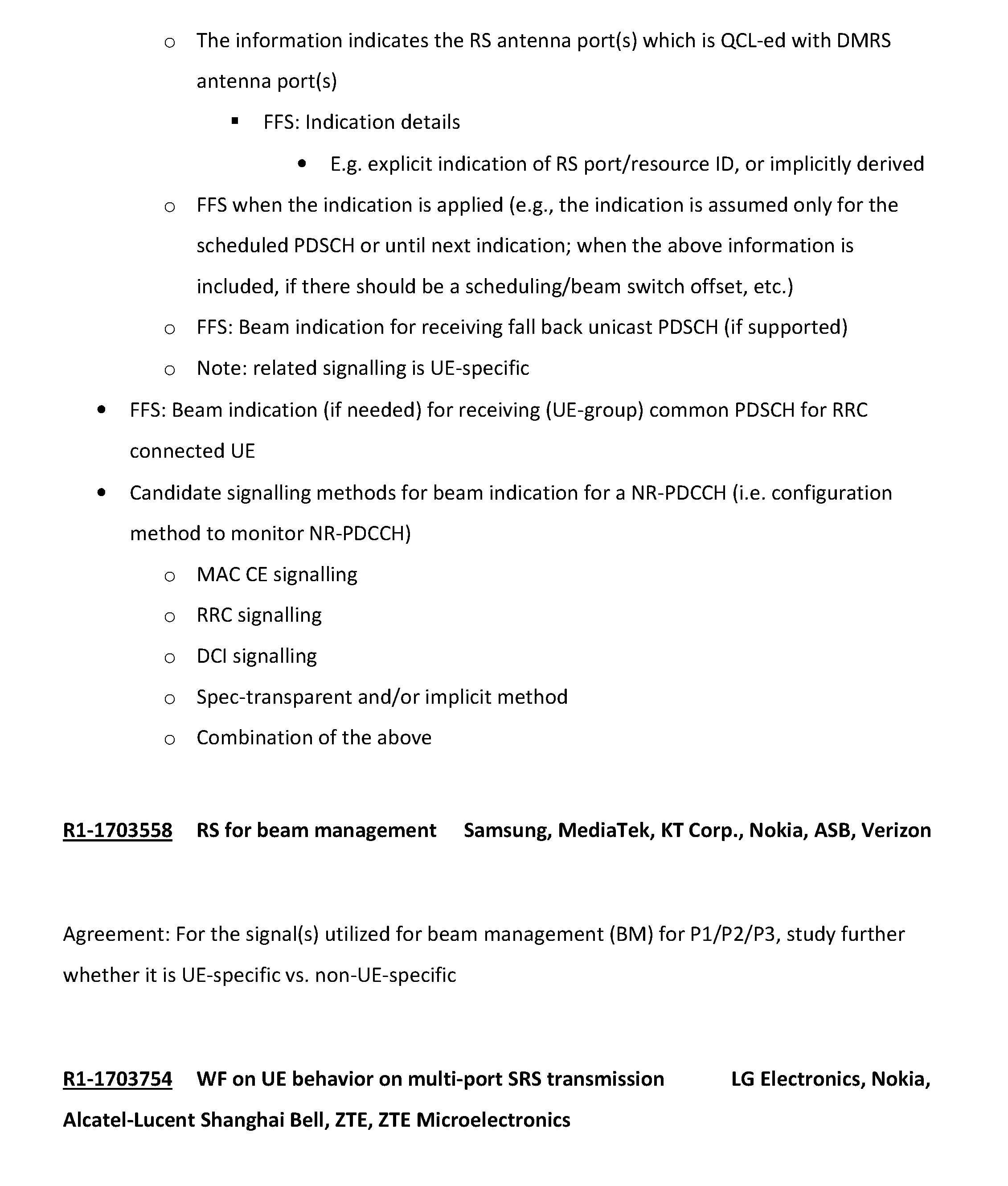
P00048

P00049

P00050
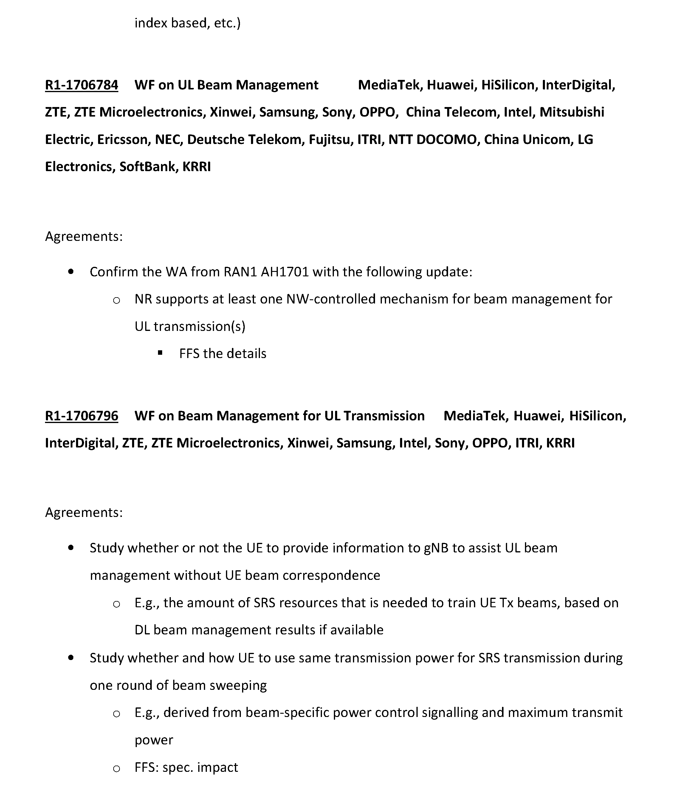
P00051
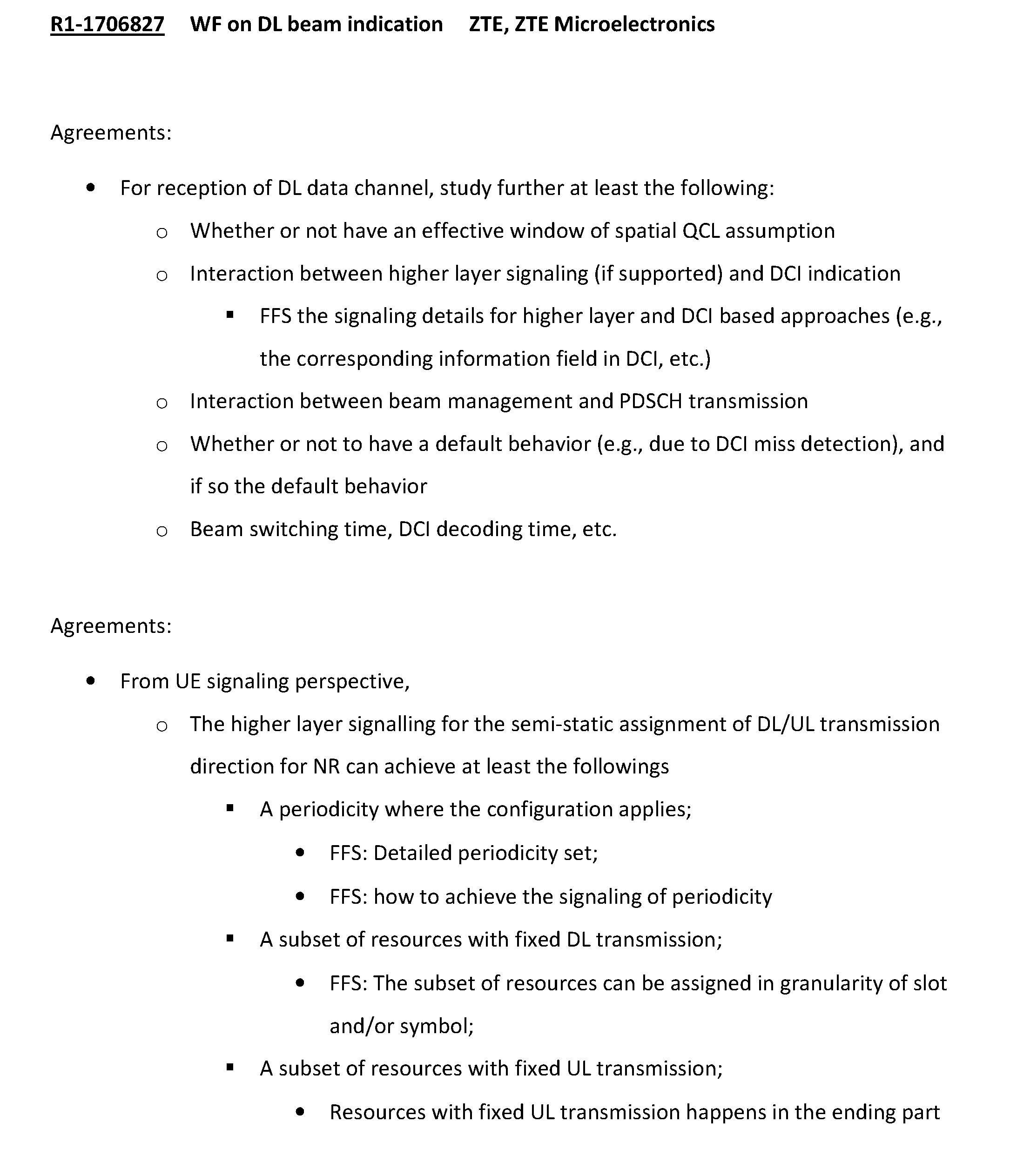
P00052
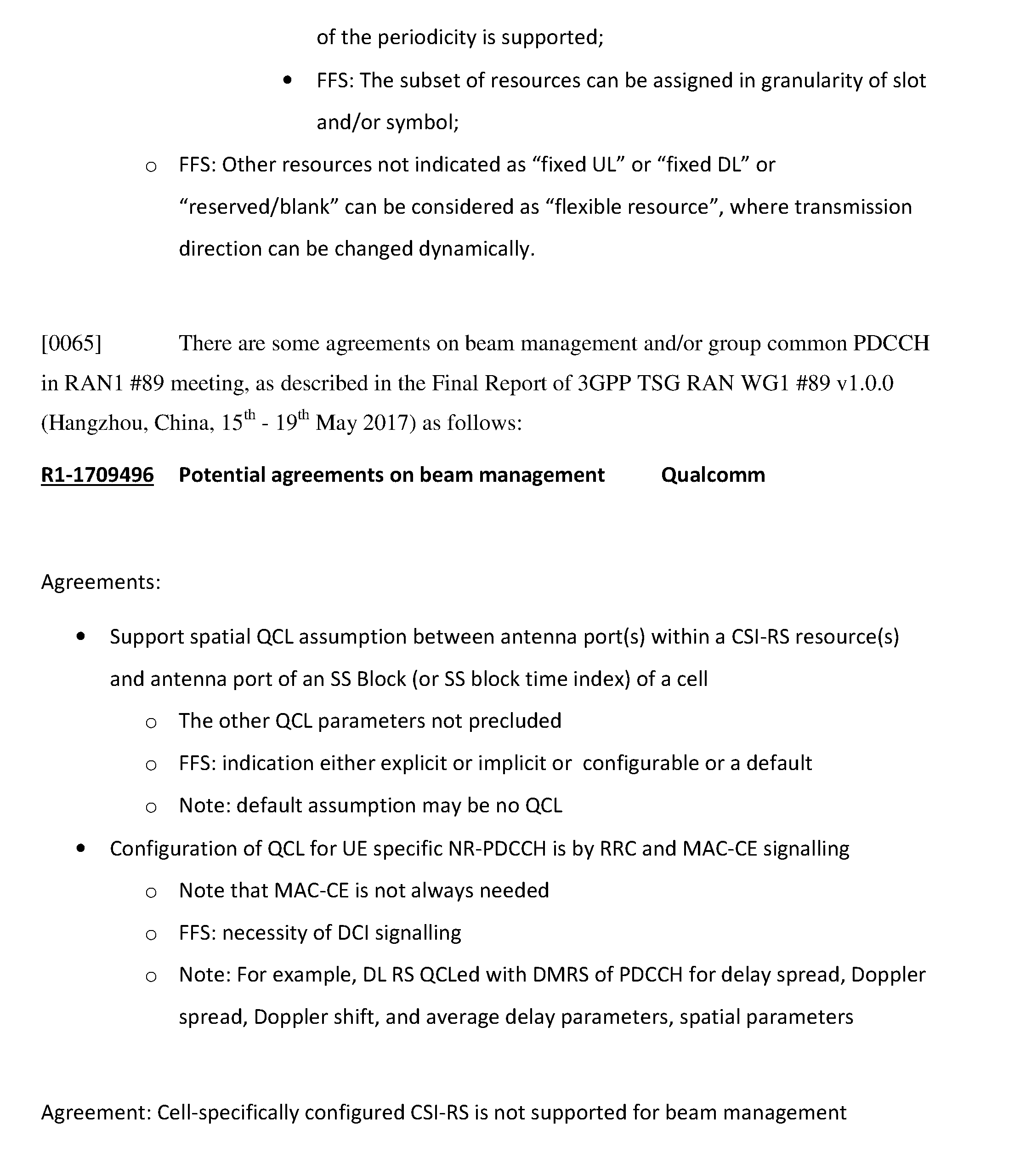
P00053
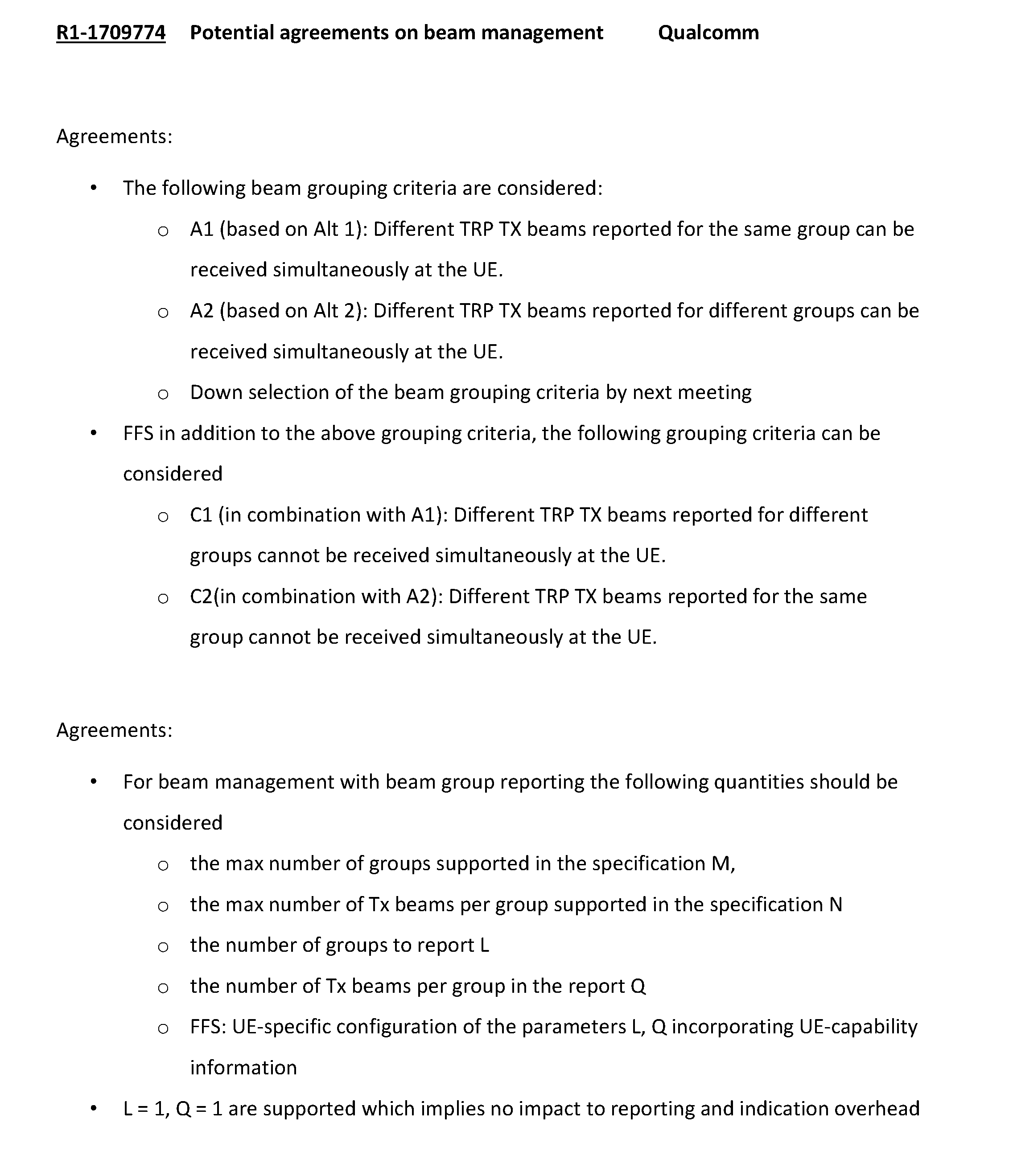
P00054
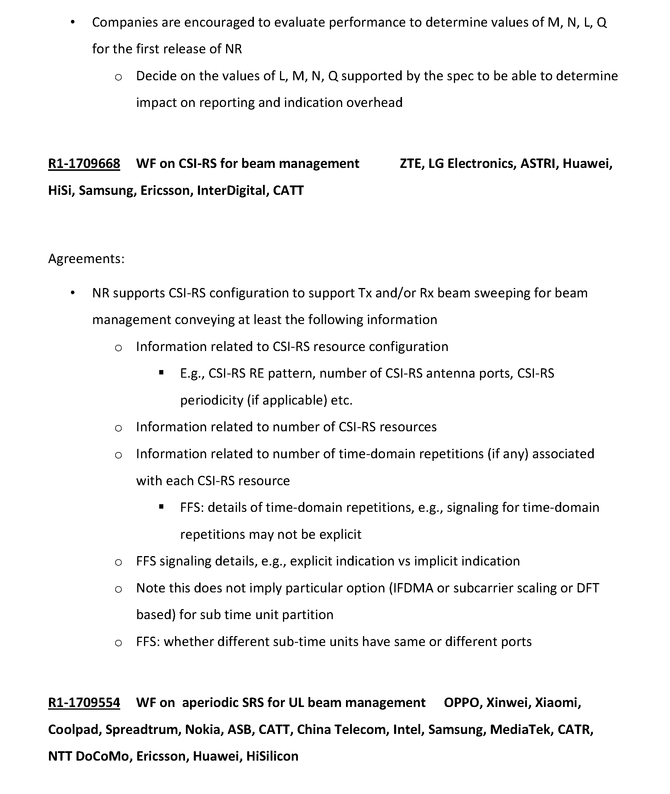
P00055
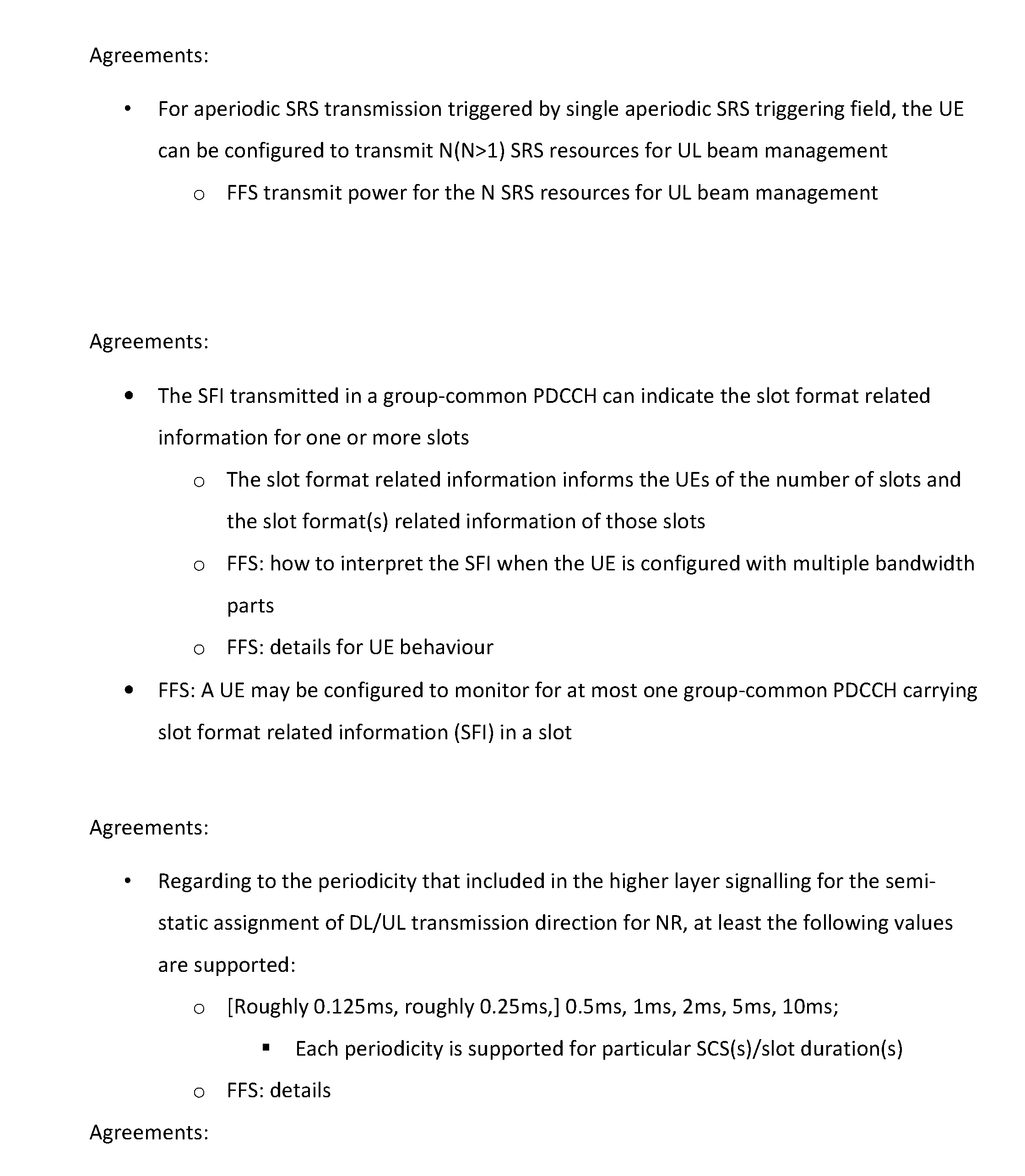
P00056
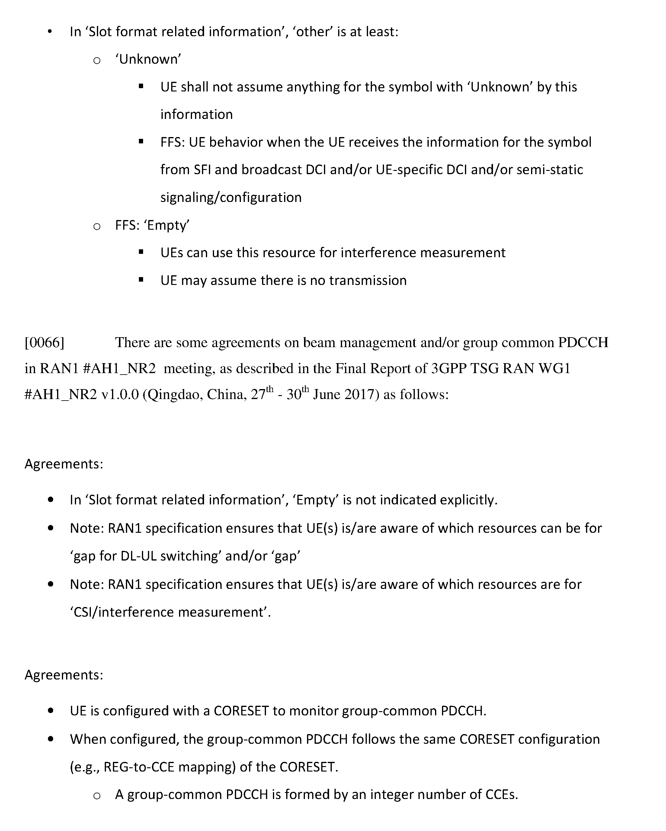
P00057
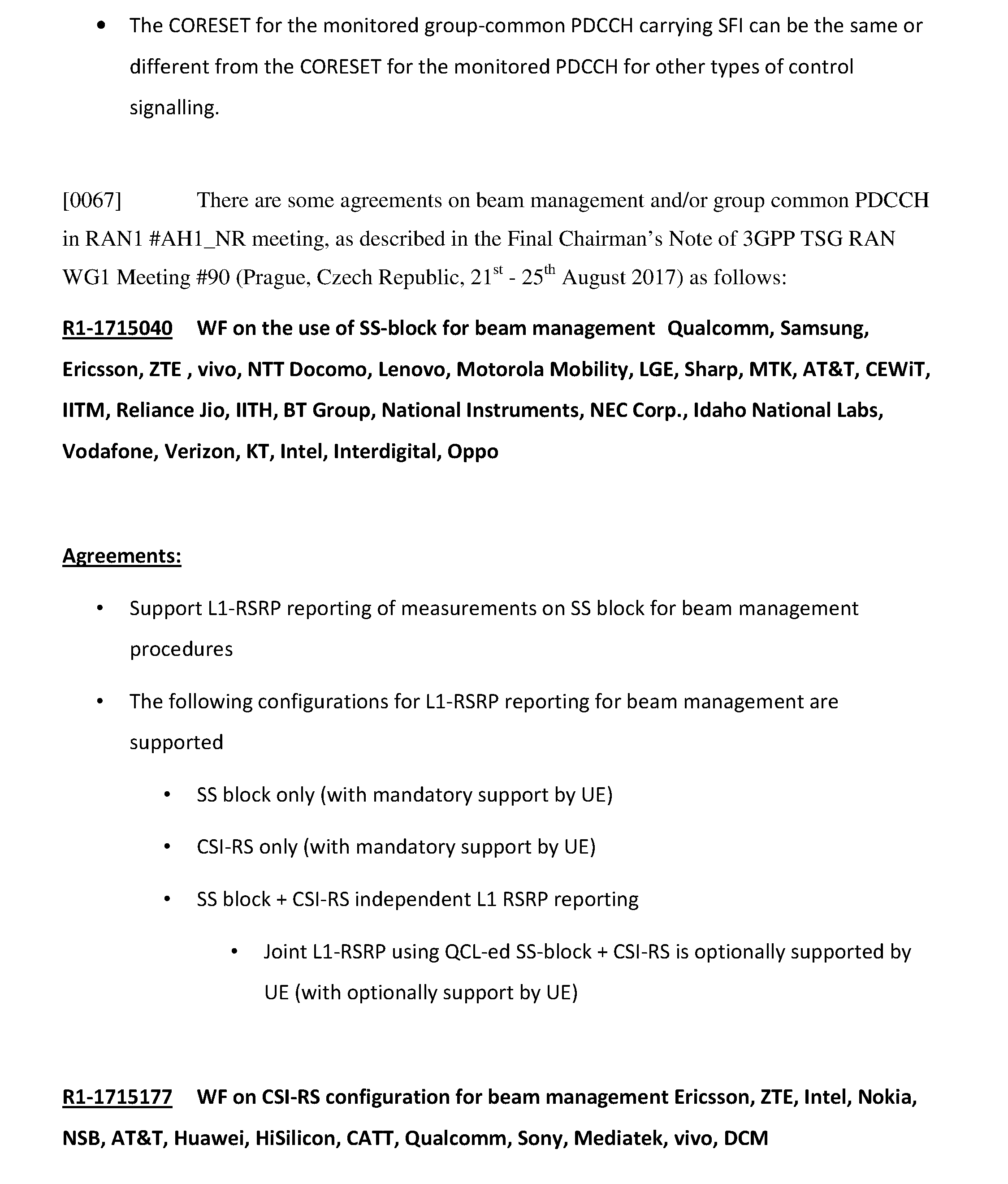
P00058
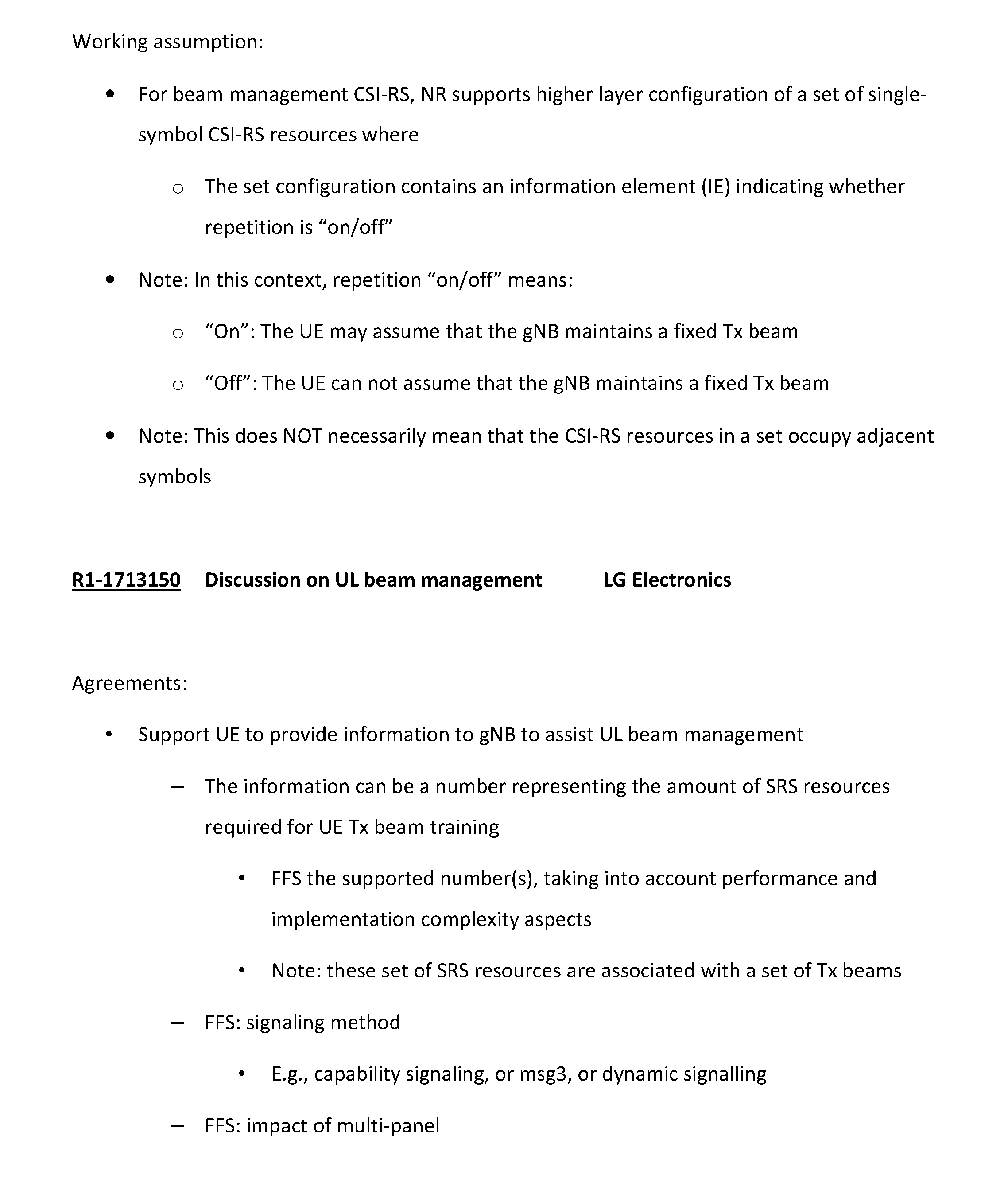
P00059

XML
uspto.report is an independent third-party trademark research tool that is not affiliated, endorsed, or sponsored by the United States Patent and Trademark Office (USPTO) or any other governmental organization. The information provided by uspto.report is based on publicly available data at the time of writing and is intended for informational purposes only.
While we strive to provide accurate and up-to-date information, we do not guarantee the accuracy, completeness, reliability, or suitability of the information displayed on this site. The use of this site is at your own risk. Any reliance you place on such information is therefore strictly at your own risk.
All official trademark data, including owner information, should be verified by visiting the official USPTO website at www.uspto.gov. This site is not intended to replace professional legal advice and should not be used as a substitute for consulting with a legal professional who is knowledgeable about trademark law.