Method For Producing A Flow Plate For A Fuel Cell
Bauer; Harald ; et al.
U.S. patent application number 16/066407 was filed with the patent office on 2019-03-14 for method for producing a flow plate for a fuel cell. The applicant listed for this patent is Robert Bosch GmbH. Invention is credited to Harald Bauer, Herbert Gruhn, Juergen Hackenberg, Helerson Kemmer.
| Application Number | 20190081331 16/066407 |
| Document ID | / |
| Family ID | 57460532 |
| Filed Date | 2019-03-14 |
| United States Patent Application | 20190081331 |
| Kind Code | A1 |
| Bauer; Harald ; et al. | March 14, 2019 |
METHOD FOR PRODUCING A FLOW PLATE FOR A FUEL CELL
Abstract
The invention relates to a method for producing a flow plate (10, 28) for a fuel cell (12), comprising a plurality of gas guide webs (14) and at least one electrically conductive and porous layer unit (16) arranged on the gas guide webs (14). It is proposed that a geometry and/or a structure of the layer unit (16) is produced during a material application onto the gas guide webs (14).
| Inventors: | Bauer; Harald; (Ehningen, DE) ; Kemmer; Helerson; (Vaihingen, DE) ; Gruhn; Herbert; (Ludwigsburg, DE) ; Hackenberg; Juergen; (Sachsenheim, DE) | ||||||||||
| Applicant: |
|
||||||||||
|---|---|---|---|---|---|---|---|---|---|---|---|
| Family ID: | 57460532 | ||||||||||
| Appl. No.: | 16/066407 | ||||||||||
| Filed: | December 2, 2016 | ||||||||||
| PCT Filed: | December 2, 2016 | ||||||||||
| PCT NO: | PCT/EP2016/079561 | ||||||||||
| 371 Date: | October 18, 2018 |
| Current U.S. Class: | 1/1 |
| Current CPC Class: | H01M 8/0245 20130101; H01M 8/04156 20130101; Y02E 60/50 20130101; H01M 8/0247 20130101; H01M 8/026 20130101; H01M 8/0202 20130101; H01M 2008/1095 20130101 |
| International Class: | H01M 8/026 20060101 H01M008/026; H01M 8/0247 20060101 H01M008/0247; H01M 8/0245 20060101 H01M008/0245 |
Foreign Application Data
| Date | Code | Application Number |
|---|---|---|
| Dec 28, 2015 | DE | 10 2015 226 753.9 |
Claims
1. A method for producing a flow plate (10, 28) for a fuel cell (12), the flow plate having a plurality of gas guide ribs (14) and with at least one porous, electrically conductive layer unit (16) arranged on the gas guide ribs (14), the method comprising generating a geometry and/or a structure of the layer unit (16) during material application onto the gas guide ribs (14).
2. The method as claimed in claim 1, characterized in that the layer unit (16) is applied at least in part to the gas guide ribs (14) using a coating method.
3. The method as claimed in claim 1, characterized in that the layer unit (16) is applied at least in part to the gas guide ribs (14) using a spray method.
4. The method as claimed in claim 1, characterized in that the layer unit (16) is applied at least in part to the gas guide ribs (14) using a thermal spray method.
5. The method as claimed in claim 1, characterized in that the layer unit (16) is applied at least in part to the gas guide ribs (14) using a 3D printing method.
6. The method as claimed in claim 1, characterized in that during application of the layer unit (16) differences in height between the gas guide ribs (14) are leveled out.
7. The method as claimed in claim 1, characterized in that catalyst particles are introduced at least into sub-regions of the layer unit (16).
8. A flow plate for a fuel cell (12), having a plurality of gas guide ribs (14) and having at least one porous, electrically conductive layer unit (16) applied to the gas guide ribs (14), which layer unit is manufactured using a method as claimed in claim 1.
9. A fuel cell having at least one membrane unit (18) and at least one flow plate (10, 28) as claimed in claim 8, wherein the layer unit (16) is arranged in a contact region (20) between the membrane unit (18) and the flow plate (10).
10. A method for providing a fuel cell, the method comprising providing at least one membrane unit (18), providing at least one flow plate (10, 28) using the method as claimed in claim 1, and arranging the layer unit (16) in a contact region (20) between the membrane unit (18) and the flow plate (10).
Description
BACKGROUND OF THE INVENTION
[0001] A method for producing a flow plate for a fuel cell, with a plurality of gas guide ribs and with at least one porous, electrically conductive layer unit arranged on the gas guide ribs, has already been proposed.
SUMMARY OF THE INVENTION
[0002] The invention is based on a method for producing a flow plate for a fuel cell, in particular for a PEM fuel cell, with a plurality of gas guide ribs and with at least one porous, electrically conductive layer unit arranged on the gas guide ribs.
[0003] It is proposed that a geometry and/or a structure of the layer unit be generated during material application onto the gas guide ribs.
[0004] A "flow plate" should in particular be understood to mean a mechanical unit which is provided for in particular electrical contacting of at least one fuel cell and/or of at least two in particular adjacent fuel cells and/or for supplying a fuel cell with a fuel gas, in particular hydrogen and/or oxygen, and/or for disposal of at least one reaction product, in particular water and/or water vapor. The flow plate may in particular be configured as a monopolar plate, a bipolar plate or end plate. In particular, the flow plate may be formed at least substantially of an embossed metal sheet. "Provided" should be understood to mean in particular designed and/or equipped. Where an item is provided for a specific function, this should in particular be understood to mean that the item fulfills and/or performs this specific function in at least one application state and/or operating state. A "fuel cell" should be understood in particular to mean a unit which is provided to convert at least one chemical reaction energy of at least one, in particular continuously supplied, fuel gas, in particular hydrogen and/or carbon monoxide, and of at least one oxidizing agent, in particular oxygen, in particular into electrical energy. The gas guide ribs are in particular provided to form a flow field. A "flow field" should in this context be understood in particular to mean a three-dimensional structure which is applied in particular by a mechanical and/or chemical and/or optical method to at least one surface of the flow plate and/or introduced at least in part into a surface of the flow plate. In particular, the flow field takes up at least 30%, advantageously at least 50% and preferably at least 75% of the surface of the flow plate. In particular, the flow field is configured as a grid flow field and/or a channel flow field, which may in particular comprise a plurality of channels extending in particular at least substantially parallel to one another and/or at least one channel extending in serpentine manner.
[0005] A "layer unit" should be understood in this context in particular to mean a unit which comprises at least one layer formed of the electrically conductive material. In particular, the layer unit may have a plurality of layers arranged one above the other. In particular, the layer unit is configured to have at least substantially open porosity. In particular, the layer unit has a plurality of cavities which are connected in particular fluidically to one another and/or with a surrounding environment. The concept of "generating" a geometry and/or a structure of the layer unit during material application to the gas guide ribs should in particular be understood to mean that the final configuration of the layer unit, for example with regard to porosity, dimensions, number of layers, layer thickness of individual layers and/or total thickness of the layer unit is formed directly during an application process of the material forming the layer unit.
[0006] As a result of such a configuration, a method of this generic type may be provided with improved characteristics with regard to the manufacture of flow plates for fuel cells. In particular, local application of a material for producing a porous, electrically conductive layer unit on gas guide ribs may advantageously save material. Furthermore, the use of additional elements, in particular elements made from metal foams, which would have been applied to the gas guide ribs, may be dispensed with, so advantageously simplifying flow plate manufacture.
[0007] It is further proposed that the layer unit be applied at least in part to the gas guide ribs using a coating method. A coating method should be understood in particular to mean a chemical, mechanical, thermal and/or thermomechanical manufacturing process which is provided for application of an at least substantially adhesive layer of at least one amorphous substance to a surface of a workpiece. This enables advantageously simple and/or inexpensive production of the layer unit on the gas guide ribs.
[0008] In one configuration of the invention, it is proposed that the layer unit be applied at least in part to the gas guide ribs using a spray method. A "spray method" should in particular be understood to mean a method in which a coating material is accelerated in particular by means of a gas stream and applied to a workpiece. The layer unit is preferably applied at least in part to the gas guide ribs using a thermal spray method. A "thermal spray method" should be understood in particular to mean a method in which a coating material is fused or melted inside or outside a spray torch, accelerated in a gas stream in the form of spray particles and flung onto at least one surface of a workpiece to be coated. This allows advantageously simple and/or inexpensive production of the layer unit on the gas guide ribs.
[0009] It is further proposed that the layer unit be applied at least in part to the gas guide ribs using a 3D printing method. In this way, a layer element may advantageously be produced which has portions with different layer characteristics, for example in terms of strength, contact resistance and/or porosity.
[0010] It is additionally proposed to level out differences in height between the gas guide ribs during application of the layer unit. In particular, layers of different layer thickness may be applied to the gas guide ribs to level out differences in height. This allows advantageously low tolerance requirements when configuring the gas guide ribs. Furthermore, advantageous contactability may be achieved for the flow plate.
[0011] It is further proposed that catalyst particles be introduced at least into sub-regions of the layer unit. In particular, the catalyst particles may be introduced into the layer unit by means of a chemical and/or electrochemical method, for example by means of an electroplating method. This results in advantageous functionalization of the layer unit.
[0012] In addition, a flow plate is proposed for a fuel cell which has a plurality of gas guide ribs and at least one porous, electrically conductive layer unit applied to the gas guide ribs. The flow plate with applied porous, electrically conductive layer unit differs from known flow plates with elements of metallic foams arranged on gas guide ribs in particular in terms of a structure of the layer unit compared with the metallic foams and in terms of connection to surfaces of the gas guide ribs. In particular, the flow plate with an applied porous, electrically conductive layer unit has the advantage of less expensive and/or simpler manufacture compared with known flow plates with elements arranged on gas guide ribs.
[0013] Furthermore, a fuel cell, in particular a PEM fuel cell, is proposed with at least one membrane unit and at least one flow plate with a plurality of gas guide ribs and with at least one porous, electrically conductive layer unit arranged on the gas guide ribs, wherein the layer unit is arranged in a contact region between the membrane unit and the flow plate. In this way, fuel cell manufacture may be advantageously simplified and manufacturing costs advantageously reduced.
[0014] The method according to the invention is not here intended to be restricted to the above-described application and embodiment. In particular, to put into effect a mode of operation described herein, the method according to the invention may comprise a number of individual elements, components and units which differs from the number stated herein.
BRIEF DESCRIPTION OF THE DRAWINGS
[0015] Further advantages are revealed by the following description of the drawings. The drawings show an exemplary embodiment of the invention. The drawings, description and claims contain numerous features in combination. A person skilled in the art will expediently also consider the features individually and combine them into meaningful further combinations.
[0016] In the figures:
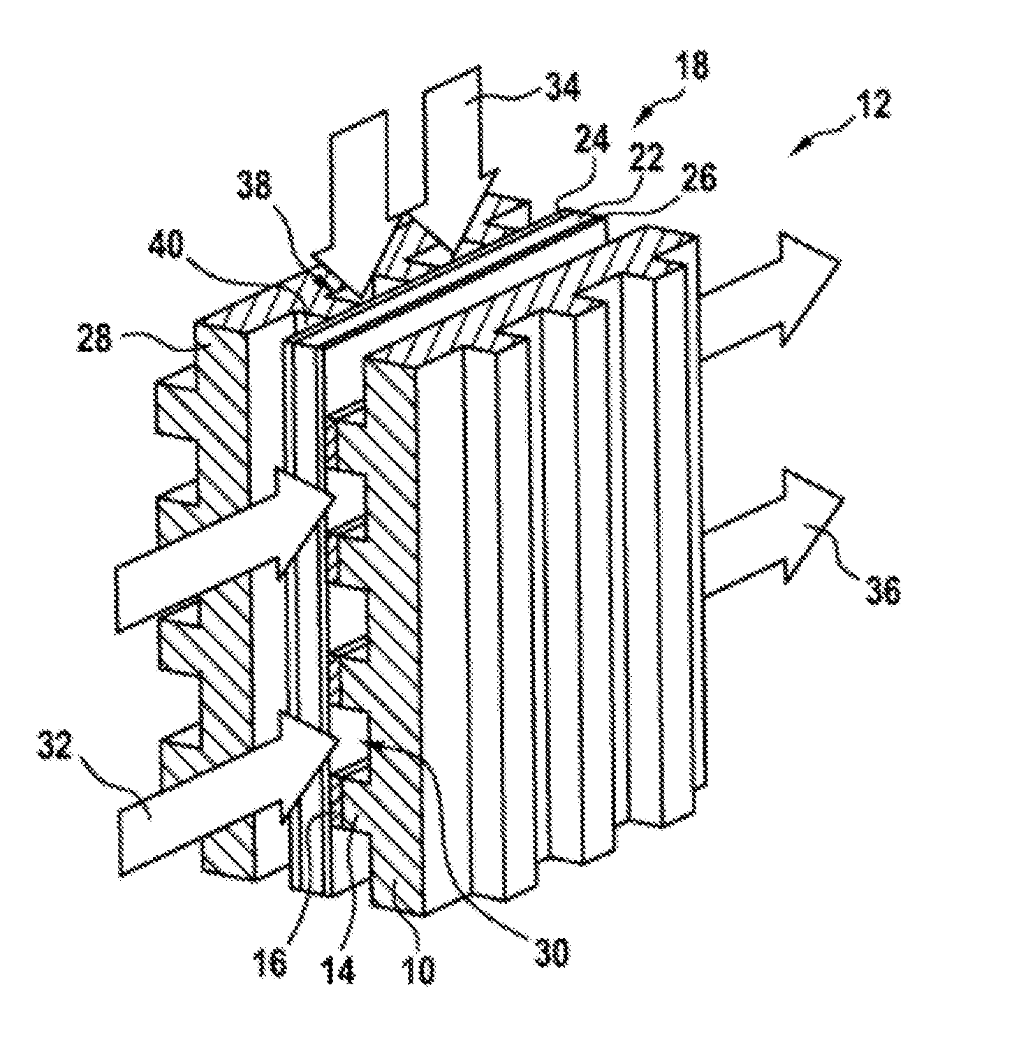
[0017] FIG. 1 is a schematic representation of a fuel cell with a membrane unit, a cathode-side flow plate and an anode-side flow plate and
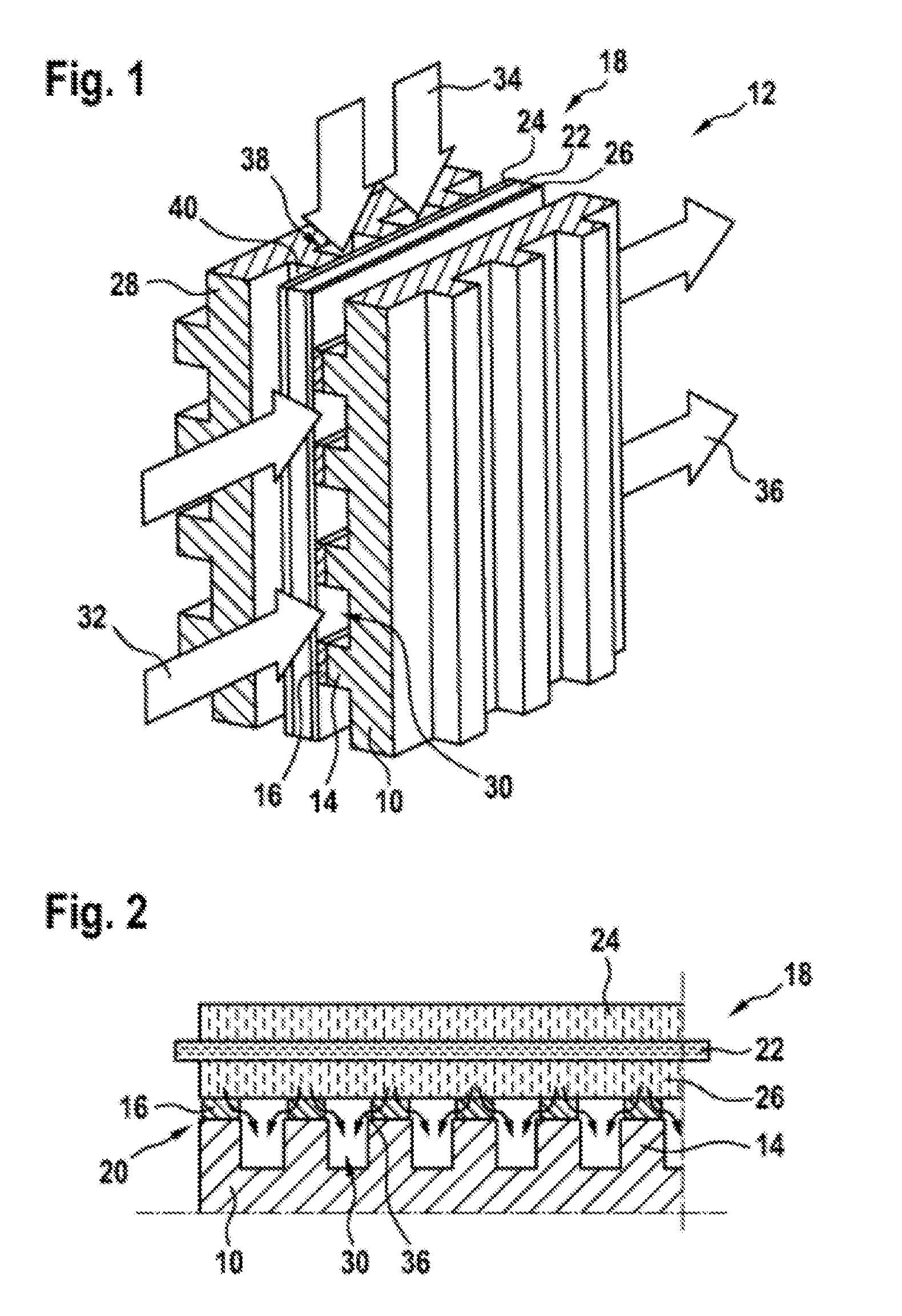
[0018] FIG. 2 is a sectional representation of the membrane unit and the cathode-side flow plate.
DETAILED DESCRIPTION
[0019] FIG. 1 is a schematic representation of a fuel cell 12. The fuel cell 12 has a membrane unit 18. The membrane unit 18 has a proton-conducting polymer membrane 22. The membrane unit 18 further has two diffusion layers 24, 26 which are arranged on either side of the polymer membrane 22. The diffusion layers 24, 26 are formed in particular of a woven carbon fabric covered with a catalytic material.
[0020] Furthermore, the fuel cell 12 has a cathode-side flow plate 10 and an anode-side flow plate 28. The membrane unit 18 is arranged between the cathode-side flow plate 10 and the anode-side flow plate 28. To produce electrical contact between the cathode-side flow plate 10 and the anode-side flow plate 28 via the membrane unit 18, the flow plates 10, 28 are pressed together with the membrane unit 18. The one anode-side flow plate 28 has a plurality of gas guide ribs 40 which form a plurality of gas channels 38 which are provided to feed a fuel gas 34, in particular hydrogen, to the membrane unit 18 on the anode side. The cathode-side flow plate 10 has a plurality of gas guide ribs 14 which form a plurality of gas channels 30 which are provided to feed oxygen 32, in particular atmospheric oxygen, to the membrane unit 18 on the cathode side and to remove water 36, in particular water vapor, arising during a reaction.
[0021] FIG. 2 is a sectional representation of the membrane unit 18 and the cathode-side flow plate 10 of the fuel cell 12. The flow plate 10 has a porous, electrically conductive layer unit 16 which has been applied to surfaces of the gas guide ribs 14. The layer unit 16 is arranged in a contact region 20 between the membrane unit 18 and the flow plate 10. As a result of the porous, electrically conductive layer unit 16, an advantageously electrical connection may be achieved, and water 36 may be advantageously guided out of the cathode-side diffusion layer 26 in the region of the gas guide ribs 14.
[0022] When manufacturing the cathode-side flow plate 10, a geometry and/or a structure of the layer unit 16 may be generated directly during material application onto the gas guide ribs 14. The layer unit 16 is applied at least in part to the gas guide ribs 14 using a coating method. The layer unit 16 is applied at least in part to the gas guide ribs 14 using a spray method, preferably using a thermal spray method. Alternatively or in addition, the layer unit 16 may be applied at least in part to the gas guide ribs 14 using a 3D printing method. During application using a 3D printing method, the layer unit 16 may be applied in such a way that sub-regions of the layer unit 16 differ from one another in particular in terms of strength, contact resistance and/or a porosity. During application of the layer unit 16, differences in height between the gas guide ribs 14 may moreover be leveled out. After application of the layer unit 16, catalyst particles may be introduced at least into sub-regions of the layer unit 16, whereby a local reaction rate of the fuel cell 12 may be advantageously increased. The anode-side flow plate 28 may be manufactured identically to the cathode-side flow plate 10.
* * * * *
D00000
D00001
XML
uspto.report is an independent third-party trademark research tool that is not affiliated, endorsed, or sponsored by the United States Patent and Trademark Office (USPTO) or any other governmental organization. The information provided by uspto.report is based on publicly available data at the time of writing and is intended for informational purposes only.
While we strive to provide accurate and up-to-date information, we do not guarantee the accuracy, completeness, reliability, or suitability of the information displayed on this site. The use of this site is at your own risk. Any reliance you place on such information is therefore strictly at your own risk.
All official trademark data, including owner information, should be verified by visiting the official USPTO website at www.uspto.gov. This site is not intended to replace professional legal advice and should not be used as a substitute for consulting with a legal professional who is knowledgeable about trademark law.