Electric Storage Device
Kenko; Takuya ; et al.
U.S. patent application number 16/186885 was filed with the patent office on 2019-03-14 for electric storage device. The applicant listed for this patent is Murata Manufacturing Co., Ltd.. Invention is credited to Masashi Higuchi, Toru Kawai, Takuya Kenko, Masahiro Otsuka.
| Application Number | 20190080855 16/186885 |
| Document ID | / |
| Family ID | 60326530 |
| Filed Date | 2019-03-14 |


| United States Patent Application | 20190080855 |
| Kind Code | A1 |
| Kenko; Takuya ; et al. | March 14, 2019 |
ELECTRIC STORAGE DEVICE
Abstract
An electric storage device includes a case having a substantially rectangular shape including a cutout part. An electrode body is disposed in the case and includes a first electrode, a second electrode, and a separator disposed between the first and second electrodes. An electrolyte is located in the case and at least partially impregnating the electrode body. A first electrode terminal is located on a first part of a side surface of the case and is electrically connected to the first electrode by a first connection member which has elasticity in a direction extending from the first electrode terminal to the first electrode. A second electrode terminal is located on a second part of the side surface of the case and is electrically connected to the second electrode by a second elastic connection member which has elasticity in a direction extending from the second electrode terminal to the second electrode.
| Inventors: | Kenko; Takuya; (Nagaokakyo-shi, JP) ; Kawai; Toru; (Nagaokakyo-shi, JP) ; Otsuka; Masahiro; (Nagaokakyo-shi, JP) ; Higuchi; Masashi; (Nagaokakyo-shi, JP) | ||||||||||
| Applicant: |
|
||||||||||
|---|---|---|---|---|---|---|---|---|---|---|---|
| Family ID: | 60326530 | ||||||||||
| Appl. No.: | 16/186885 | ||||||||||
| Filed: | November 12, 2018 |
Related U.S. Patent Documents
| Application Number | Filing Date | Patent Number | ||
|---|---|---|---|---|
| PCT/JP2017/018821 | May 19, 2017 | |||
| 16186885 | ||||
| Current U.S. Class: | 1/1 |
| Current CPC Class: | H01M 2/0285 20130101; H01G 11/72 20130101; H01M 2/30 20130101; Y02E 60/10 20130101; H01M 10/058 20130101; H01G 11/52 20130101; H01G 11/78 20130101; H01G 11/58 20130101; H01M 2/0202 20130101; H01M 2/06 20130101; H01M 2/26 20130101; H01G 11/26 20130101; H01G 11/76 20130101; H01M 2220/30 20130101; H01M 2002/0205 20130101; H01G 11/74 20130101; H01M 10/0436 20130101; H01G 11/66 20130101; H01M 2/0217 20130101 |
| International Class: | H01G 11/78 20060101 H01G011/78; H01G 11/52 20060101 H01G011/52; H01G 11/26 20060101 H01G011/26; H01G 11/58 20060101 H01G011/58; H01M 2/30 20060101 H01M002/30; H01M 2/06 20060101 H01M002/06; H01M 2/26 20060101 H01M002/26 |
Foreign Application Data
| Date | Code | Application Number |
|---|---|---|
| May 20, 2016 | JP | 2016-101183 |
Claims
1. An electric storage device comprising: a case having a substantially rectangular shape including a cutout part; an electrode body disposed in the case and including a first electrode, a second electrode, and a separator disposed between the first and second electrodes; an electrolyte located in the case and at least partially impregnating the electrode body; a first electrode terminal located on a first part of a side surface of the case and being electrically connected to the first electrode by a first connection member which has elasticity in a direction extending from the first electrode terminal to the first electrode; and a second electrode terminal located on a second part of the side surface of the case and being electrically connected to the second electrode by a second elastic connection member which has elasticity in a direction extending from the second electrode terminal to the second electrode.
2. The electric storage device according to claim 1, wherein the first and second terminals are each provided on respective parts of the side surface of the case which do not form part of the cutout part.
3. The electric storage device according to claim 2, wherein a virtual straight line connecting a center of the first electrode terminal and a center of the second electrode terminal does not overlap with the electrode body in plan view.
4. The electric storage device according to claim 1, wherein a virtual straight line connecting a center of the first electrode terminal and a center of the second electrode terminal does not overlap with the electrode body in plan view.
5. The electric storage device according to claim 1, wherein: the first electrode includes a first electrode body and a first extended part extending from the first electrode body; the second electrode includes a second electrode body facing and a second extended part extending from the second electrode body, the first and second electrode bodies facing one another; the first connection member is constituted by a plate member including a first part connected to the first extended part, a second part connected to the first connection member, and a first bent part connecting the first and second parts; and the second connection member is constituted by a plate member including a third part connected with the second extended part, a fourth part connected with the second connection member, and a second bent part connecting the third and fourth parts.
6. The electric storage device according to claim 1, wherein: the first electrode, the second electrode, and the separator are integrated in the electrode body; and the electrode body and the case are physically joined together.
7. The electric storage device according to claim 6, the electrode body and the case are physically joined together by an adhesive layer bonding the electrode body and the case.
8. The electric storage device according to any one of claim 1, wherein one of the first and second electrode terminals are formed by the case.
Description
CROSS REFERENCE TO RELATED APPLICATIONS
[0001] The present application is a continuation of International application No. PCT/JP2017/018821, filed May 19, 2017, which claims priority to Japanese Patent Application No. 2016-101183, filed May 20, 2016, the entire contents of each of which are incorporated herein by reference.
TECHNICAL FIELD
[0002] The present invention relates to an electric storage device.
BACKGROUND OF THE INVENTION
[0003] Conventionally, electric storage devices have been used as power sources for various kinds of electronic devices. For example, Japanese Patent Application Laid-open No. 2004-6226 (Patent Document 1) discloses a battery including an electrode body obtained by laminating and winding a positive electrode, a separator, and a negative electrode.
[0004] In some cases, when the size of an electronic device needs to be reduced, only an installation space which does not have a rectangular shape in plan view can be used as an installation space for an electrical storage device in the electronic device. For this reason, an electrical storage device not having a rectangular shape in plan view is desired.
[0005] Impact resistance is also required for the electric storage device.
[0006] It is a main object of the present invention to provide an electrical storage device which does not have a rectangular shape in plan view but which does have excellent impact resistance.
BRIEF DESCRIPTION OF THE INVENTION
[0007] In accordance with one aspect of the invention, an electric storage device includes a case having a substantially rectangular shape including a cutout part. An electrode body is disposed in the case and includes a first electrode, a second electrode, and a separator disposed between the first and second electrodes. An electrolyte is located in the case and at least partially impregnates the electrode body. A first electrode terminal is located on a first part of a side surface of the case and is electrically connected to the first electrode by a first connection member which has elasticity in a direction extending from the first electrode terminal to the first electrode. A second electrode terminal is located on a second part of the side surface of the case and is electrically connected to the second electrode by a second elastic connection member which has elasticity in a direction extending from the second electrode terminal to the second electrode.
[0008] In a preferred aspect of the invention, the positive and negative electrode terminals are each provided on respective parts of the side surface of the case which do not form part of the cutout part.
[0009] In accordance with a further aspect of the invention, a virtual straight line connecting a center of the first electrode terminal and a center of the second electrode terminal does not overlap with the electrode body in plan view.
[0010] In a preferred embodiment, the first electrode includes a first electrode body and a first extended part extending from the first electrode body and the second electrode includes a second electrode body facing and a second extended part extending from the second electrode body. The first and second electrode bodies face one another. The first connection member is constituted by a plate member including a first part connected to the first extended part, a second part connected to the first connection member, and a first bent part connecting the first and second parts. The second connection member is constituted by a plate member including a third part connected with the second extended part, a fourth part connected with the second connection member, and a second bent part connecting the third and fourth parts.
[0011] In an aspect of the invention, the first electrode, the second electrode, and the separator are integrated in the electrode body and the electrode body and the case are physically joined together.
[0012] In an aspect of the invention, the electrode body and the case are physically joined together by an adhesive layer bonding the electrode body and the case.
[0013] In at least one embodiment, the first and second electrode terminals are formed by the case.
[0014] The present invention can provide an electric storage device not having a rectangular shape in plan view but having excellent impact resistance.
BRIEF DESCRIPTION OF DRAWINGS
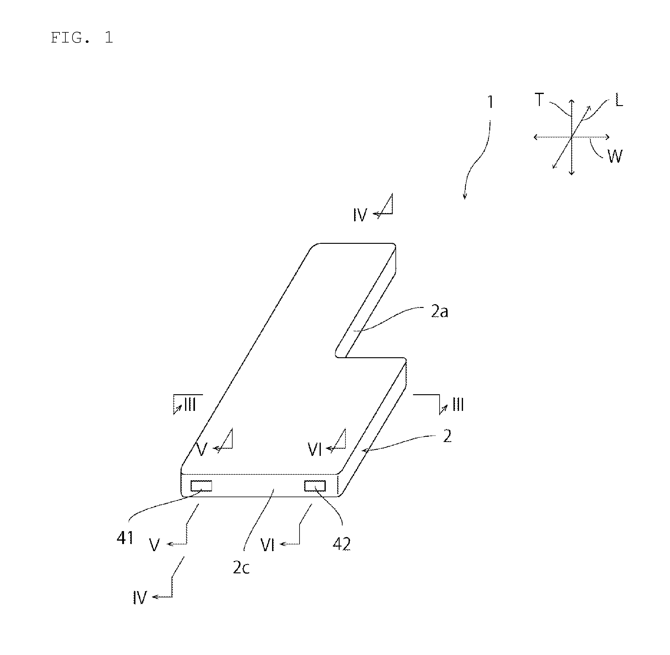
[0015] FIG. 1 is a schematic perspective view of an electric storage device according to a first embodiment.
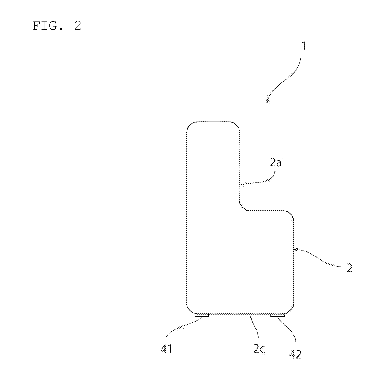
[0016] FIG. 2 is a schematic plan view of the electric storage device according to the first embodiment.
[0017] FIG. 3 is a schematic cross-sectional view taken along line III-III in FIG. 1.
[0018] FIG. 4 is a schematic plan view of part of the electric storage device according to the first embodiment.
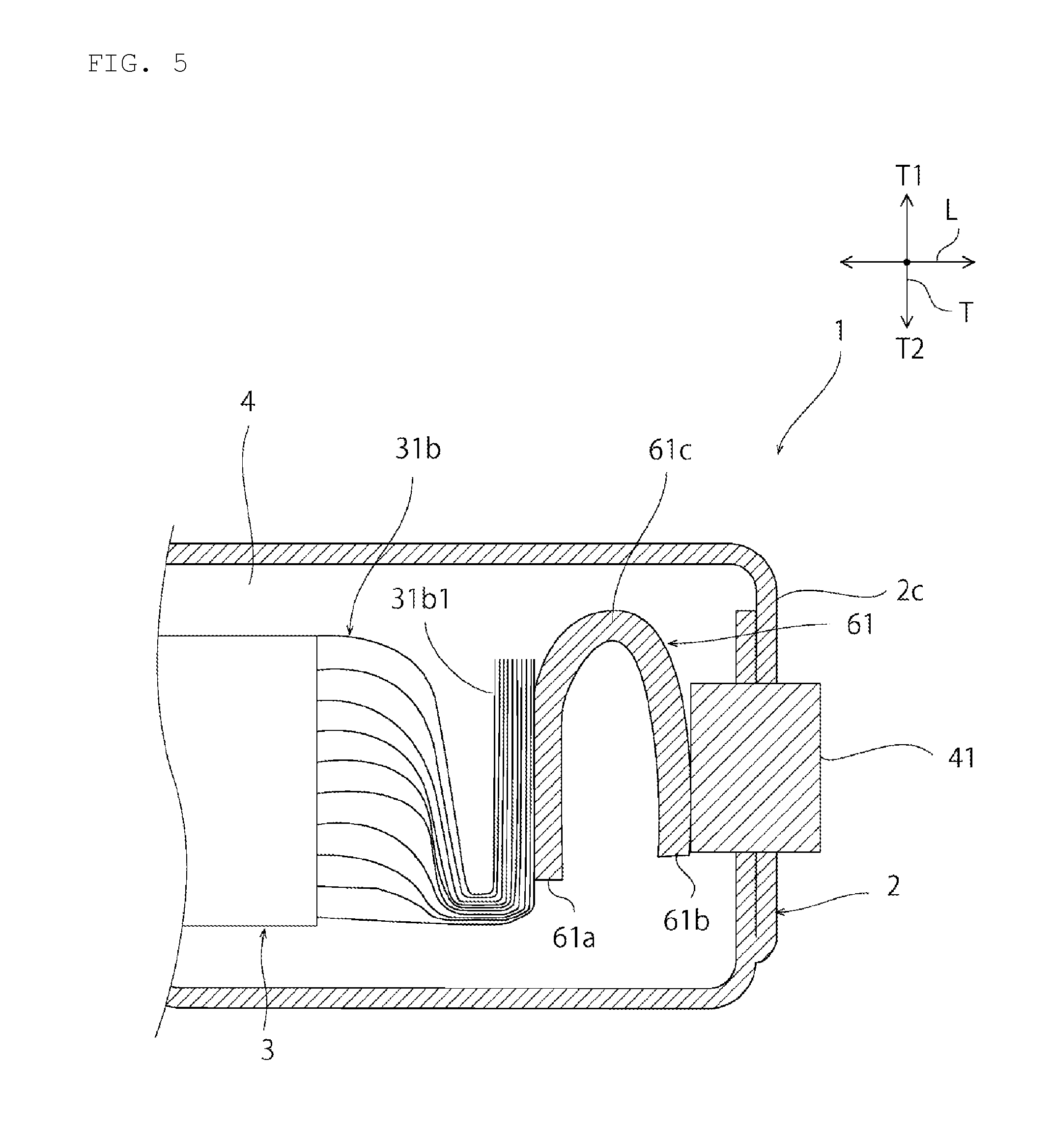
[0019] FIG. 5 is a schematic cross-sectional view taken along line V-V in FIG. 1.
[0020] FIG. 6 is a schematic cross-sectional view taken along line VI-VI in FIG. 1.
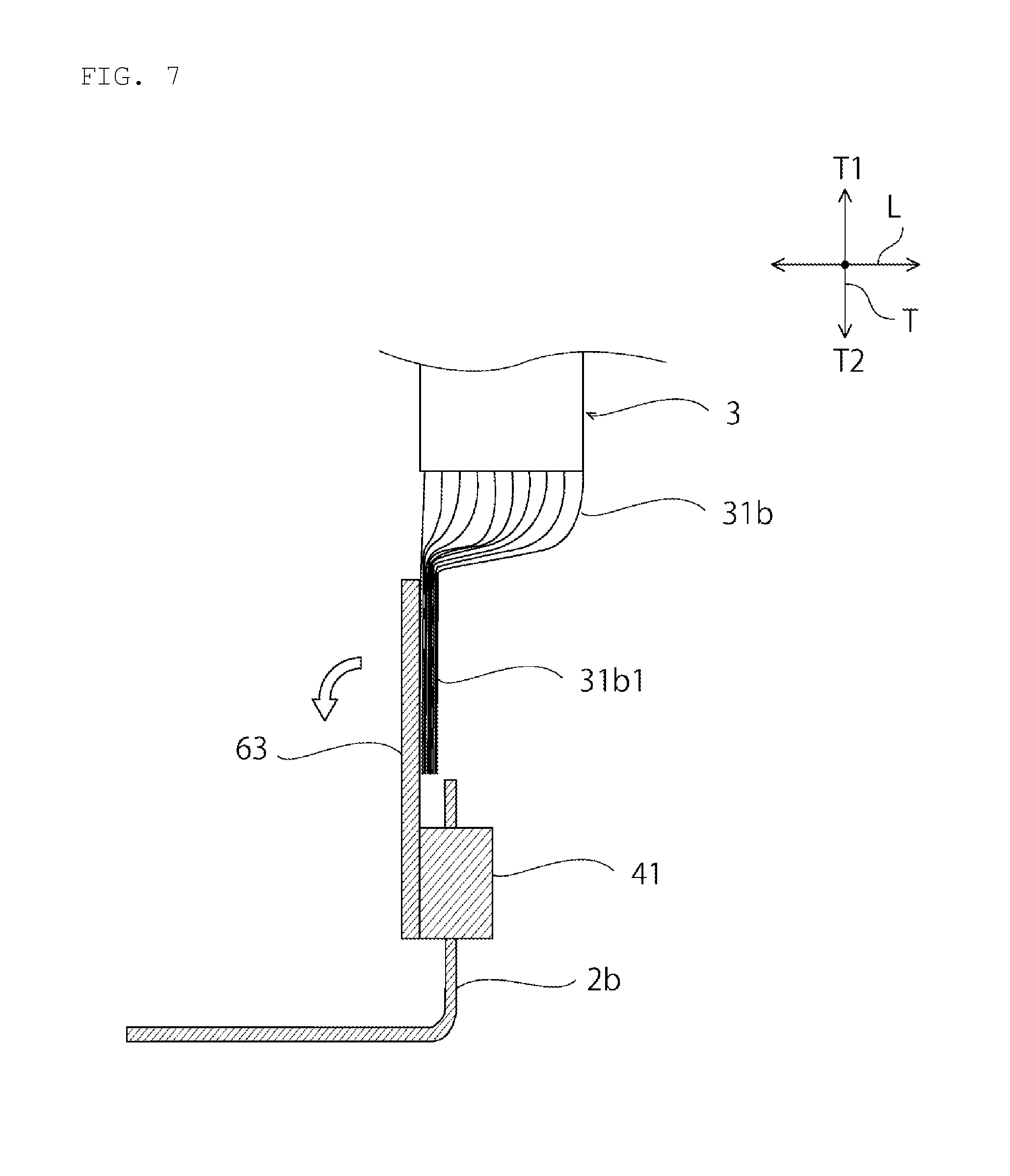
[0021] FIG. 7 is a schematic cross-sectional view for description of a method of manufacturing the electric storage device according to the first embodiment.
[0022] FIG. 8 is a schematic cross-sectional view of an electric storage device according to a second embodiment.
[0023] FIG. 9 is a schematic cross-sectional view of an electric storage device according to a third embodiment.
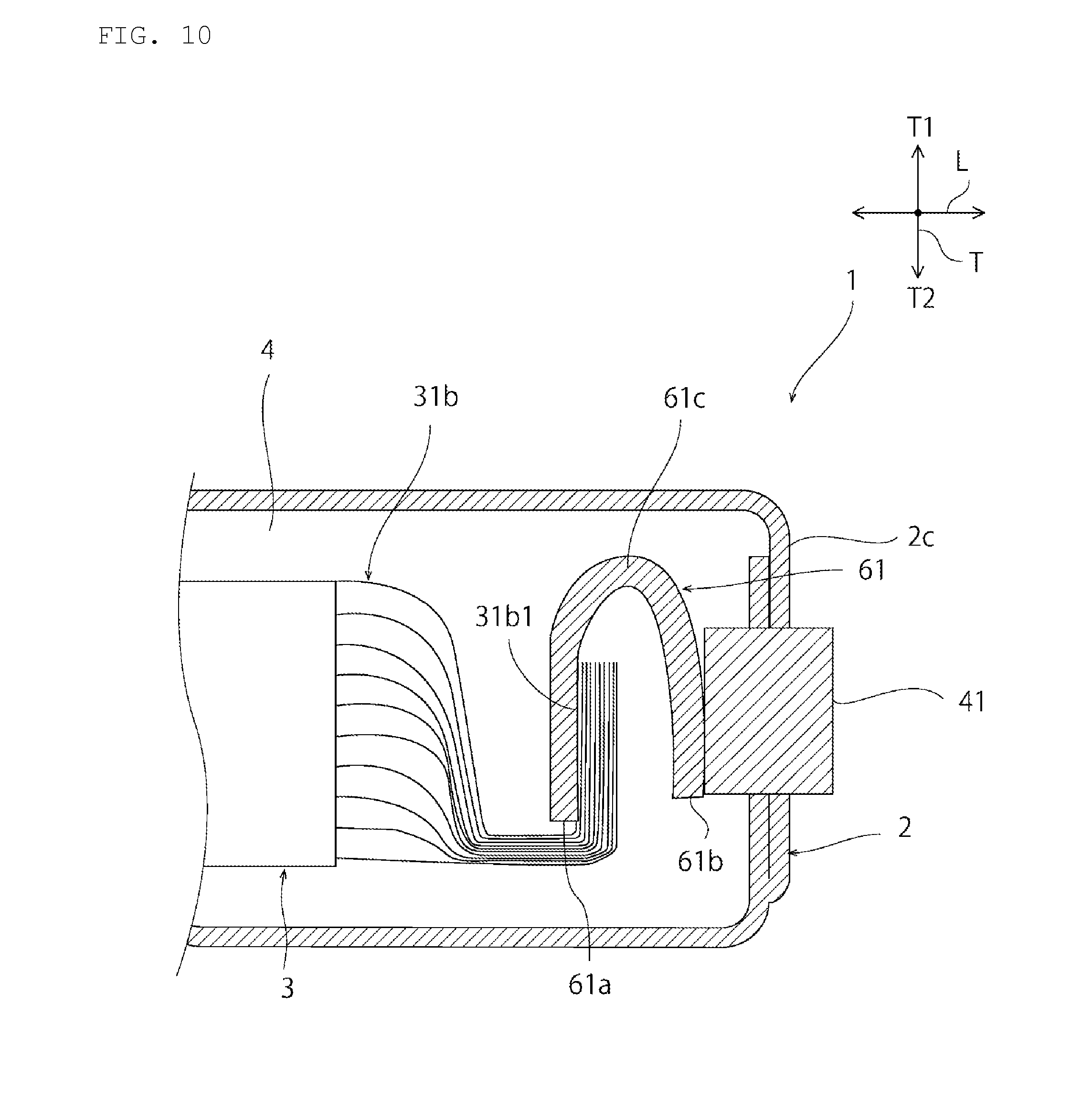
[0024] FIG. 10 is a schematic cross-sectional view of part of an electric storage device according to a fourth embodiment.
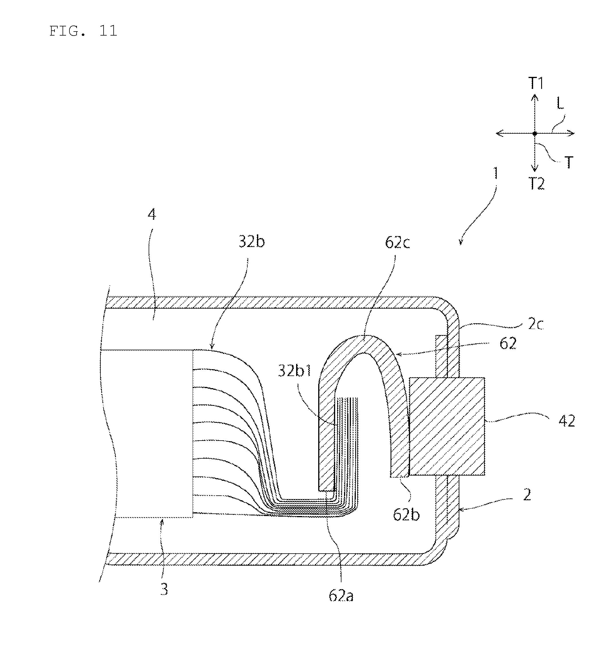
[0025] FIG. 11 is a schematic cross-sectional view of part of the electric storage device according to the fourth embodiment.
MODE FOR CARRYING OUT THE INVENTION
[0026] Exemplary preferred embodiments of the invention will be described below. The following embodiments are merely exemplary and the invention is not limited to the following embodiments.
[0027] In drawings referred to in the embodiments and the like, components having effectively identical functions will be denoted by an identical reference number. The drawings referred to in the embodiments and the like are schematically illustrated. For example, the dimensional ratios of objects illustrated in the drawings are different from the dimensional ratio of objects in reality in some cases. For example, the dimensional ratios of objects are also different between the drawings in some cases. For example, specific dimensional ratios of objects should be determined based on the following description.
First Embodiment
[0028] An electric storage device 1 illustrated in FIGS. 1 to 4 includes an electrolyte 4 (see FIG. 3) such as electrolytic solution. Specifically, the electric storage device 1 may be, for example, a battery such as a secondary battery, or a capacitor such as an electric double-layer capacitor.
[0029] As illustrated in FIGS. 1 to 3, the electric storage device 1 includes a case 2 having a generally rectangular shape including a cutout part 2a in plan view (i.e., as viewed in FIG. 2). As used herein, the phrase a "rectangular shape including a cutout part" includes a rectangular shape including a cutout part and rounded corners.
[0030] In the electric storage device 1, the cutout part 2a also has a substantially rectangular shape in plan view (again, as viewed in FIG. 3). Specifically, a single cutout part 2a having a substantially rectangular shape with rounded inner and outer corners is provided. However, the present invention is not limited to this configuration. For example, the case may be provided with a plurality of cutout parts. For example, a cutout part may be provided at each of a plurality of corners of the case. The shape of the cutout part provided to the case is not limited, too. The cutout part provided to the case may have, for example, an arcuate shape, a polygonal shape, or a shape that is a combination thereof.
[0031] The case 2 may be made of a conductor or an insulator. The case 2 may, for example, be made of metal such as aluminum, stainless steel, or copper, or an insulator such as resin.
[0032] As illustrated in FIG. 3, an electrode body 3 is disposed inside the case 2. The electrode body 3 includes a plurality of positive electrodes 31, a plurality of negative electrodes 32, and a plurality of separators 33. Each positive electrode 31 faces an adjacent negative electrode 32 with a respective separator 33 located there between to form a positive/negative electrode pair. The separator 33 insulates the positive and negative electrodes 31 and 32. In the present embodiment, each positive electrode 31 is surrounded by a pair of separators 33 (one located above the positive electrode 31 and one located below the positive electrode 31) and lateral side edges of those separators are connected with each other to form a separator bag 33a with the positive electrode 31 disposed therein. However, in the present invention, separators which are adjacent to each other in the lamination direction T do not have to be joined into a bag shape.
[0033] The present embodiment describes an example in which the electrode body 3 is a laminated electrode body obtained by laminating the plurality of sheet shaped positive electrodes 31, the plurality of sheet shaped separators 33, and the plurality of sheet shaped negative electrode 32. However, the present invention is not so limited. The electrode body is not particularly limited as long as the electrode body has a configuration that allows the accumulation of electrical power. For example, the electrode body may be achieved by a wound body obtained by winding a lamination sheet in which a plurality of positive/negative electrode pairs are provided, each positive/negative electrode pair including a respective positive electrode, a respective separator, and a respective negative electrode, all of which are laminated in the stated order.
[0034] The configuration of the positive electrode 31 may be determined as appropriate in accordance with the type of the electric storage device 1 it is used in. For example, when the electric storage device 1 is a secondary battery, the positive electrode 31 may include a positive electrode collector, and an active material layer provided on at least one surface of the positive electrode collector. For example, when the electric storage device 1 is an electric double-layer capacitor, the positive electrode 31 may include a positive electrode collector, and a polarizable electrode layer provided on at least one surface of the positive electrode collector.
[0035] The configuration of the negative electrode 32 may similarly be determined as appropriate in accordance with the type of the electric storage device 1 it is used in. For example, when the electric storage device 1 is a secondary battery, the negative electrode 32 may include a negative electrode collector, and an active material layer provided on at least one surface of the negative electrode collector. By way of further example, when the electric storage device 1 is an electric double-layer capacitor, the negative electrode 32 may include a negative electrode collector and a polarizable electrode layer provided on at least one surface of the negative electrode collector.
[0036] Some or all of the separators 33 may be, for example, a porous sheet including open cells through which ions in an electrolyte are movable. The separators 33 may be made of, for example, polypropylene, polyethylene, polyimide, cellulose, aramid, polyvinylidene fluoride, or Teflon (registered trademark). The surface of the separators 33 may be covered by an inorganic particle coat layer, a bonding layer, or the like. The surface of the separators 33 may have a bonding property. The separators 33 may be a single-layer film made of one kind of material, or may be a composite film or multi-layered film made of one or two or more types of material.
[0037] In place of the separators 33, or in addition to the separators 33, an insulation layer such as an inorganic particle coat layer may be provided on the surface of each of the positive electrode 31 and the negative electrode 32. In such a case, the insulator acts as the separator (and can be considered a separator for the purpose of the present invention.
[0038] In each of the positive and negative electrodes 31 and 32, an undercoat layer containing, for example, carbon may be provided between the collector and the active material layer.
[0039] As noted above, each of the positive/negative electrode pairs comprises a respective positive electrode 31, a respective separator 33 and a respective negative electrode 32 which are laminated together in the stated order. Each of the positive/negative electrode pairs are also laminated together to form a laminated body 70. The outer lateral edges of the separators 33 are then adhered together (and, in the preferred embodiment) bent upwardly as viewed in FIG. 3 to form the integrated electrode body 3. Specifically, a first insulation tape 51 is provided on a W1 side (the left side as viewed in FIG. 3) of the laminated body 70 and extends from the second main surface 70b of the laminated body 70, upwardly across the left lateral edge of the laminated body (so as to adhere the left lateral edges of the separators 33 to each other and to push them upwardly) and onto the first main surface 70a of the laminated body 70. As a result, at least a lateral leading end part of a first end part 33e1 of the separators 33 are held so that at least the leading end part of the first end part 33e1 is bent upwardly (more generally, toward one side (T1 side)) in the lamination direction T.
[0040] A second insulation tape 52 is provided on a W2 side (the right side as viewed in FIG. 3) of the laminated body 70 and extends from the second main surface 70b of the laminated body 70, upwardly across the right lateral edge of the laminated body (so as to adhere the right lateral edges of the separators 33 to each other and to push them upwardly) and onto the first main surface 70a of the laminated body 70. As a result, at least a lateral leading end part of a second end part 33e2 of the separators 33 are held so that at least the leading end part of the second end part 33e2 is bent upwardly (more generally, toward one side (T1 side)) in the lamination direction T.
[0041] The method of joining the insulation tapes 51 and 52 with the laminated body 70 is not particularly limited. For example, the insulation tapes 51 and 52 may be joined with the laminated body 70 directly or by adhesive bonding using an adhesive bonding agent. The insulation tapes 51 and 52 may be formed of adhesive bonding tapes and bonded to the laminated body 70. The insulation tapes 51 and 52 may be formed of double-sided adhesive bonding tapes and bonded to the laminated body 70, and the laminated body 70 may be bonded and fixed to the case 2 through the insulation tapes 51 and 52. This configuration effectively reduces displacement of the laminated body 70 in the case 2. Alternatively, the insulation tapes 51 and 52 and the laminated body 70 may be fixed together by using an adhesive bonding tape different from the insulation tapes 51 and 52.
[0042] As used herein, "adhesive bonding" includes "adhesion" and "bonding". Thus, an adhesive bonding agent includes both an adhesive agent and a bonding agent. An adhesive bonding tape includes an adhesive tape and a bonding tape.
[0043] The insulation tape 5 may be, for example, a tape made of resin such as polyimide, polypropylene, or acrylic, or metal foil such as aluminum foil, copper foil, stainless steel foil, or nickel foil, the surface of which is coated with an insulation layer.
[0044] In the electrode body 3, the positive electrode 31 and the separator 33 may be bonded to each other through a bonding agent, and the negative electrode 32 and the separator 33 may be bonded to each other through a bonding agent.
[0045] The electrode body 3 and the case 2 are joined together. Specifically, as illustrated in FIG. 3, the electrode body 3 is bonded and fixed to an inner surface of the case 2 through a bonding layer 6. In FIG. 3, the electrode body 3 is joined on the upper side (T1 side) relative to the case 2, but may also or alternatively be joined on the lower side. The electrode body 3 may also be joined to inner surfaces of the case 2 on both sides in the thickness direction T.
[0046] As illustrated in FIG. 4, each of the positive electrodes 31 includes a generally rectangular positive electrode body 31a and a first extended part 31b which extends from the positive electrode body 31a in a length direction L. Each of the negative electrodes 32 includes a generally rectangular negative electrode body 32a and a second extended part 32b which extends from the negative electrode body 32a in the length direction L. While this is preferred, the first and/or second extended parts may extended in directions other than the length direction L.
[0047] As illustrated in FIGS. 1, 2, 4, and 5, a positive electrode terminal 41 is provided on a side surface 2c of one side of the case 2 in the length direction L. The positive electrode terminal 41 is electrically connected with each of the first extended parts 31b of the positive electrodes 31. Specifically, as illustrated in FIG. 5, each of the first extended parts 31b, which are physically and electrically connected to one another, are bent such that their leading end part 31b1 extends upwardly (as viewed in FIG. 3) toward the T1 side along the lamination direction T. The leading end parts 31b1 are connected to the positive electrode terminal 41 through a first connection member 61.
[0048] The first connection member 61 includes a first part 61a which is physically and electrically connected to the first extended parts 31b1, a second part 61b which is physically and electrically connected to the positive electrode terminal 41 and a first bent part 61c which physically and electrically connects the first and second parts 61a and 61b and which protrudes upwardly (as viewed in FIG. 3) toward the T1 side. The first connection member 61 is preferably an elastic member made of, for example, metal. Accordingly, the first connection member 61 is elastic in the length direction L.
[0049] As illustrated in FIGS. 1, 2, 4, and 6, a negative electrode terminal 42 is provided on the side surface 2c of the case 2. The negative electrode terminal 42 is electrically connected with the second extended parts 32b which are physically and electrically connected to one another. Specifically, as illustrated in FIG. 6, each of the first extended parts 32b are bent such that their leading end part 32b1 extends upwardly (as viewed in FIG. 3) toward the T1 side along the lamination direction T. The leading end parts 32b1 are connected to the negative electrode terminal 42 through a first connection member 62.
[0050] The second connection member 62 includes a third part 62a which is electrically and physically connected with the second extended parts 32b, a fourth part 62b which is physically and electrically connected with the negative electrode terminal 42, and a second bent part 62c which physically and electrically connects the third part 62a and to the fourth part 62b and which protrudes toward the T1 side. The second connection member 62 is an elastic member made of, for example, metal. Accordingly, the second connection member 62 is elastic in the length direction L.
[0051] The electric storage device 1 includes the first and second connection members 61 and 62 which are both elastic in the length direction L. With this configuration, when, for example, stress, impact, or vibration is applied to the electric storage device 1, transfer of the stress or the like to the electrode body 3 is buffered by the first and second connection members 61 and 62. Accordingly, the electric storage device 1 has excellent impact resistance.
[0052] The electrode body 3 and the case 2 are joined together which prevents the electrode body 3 from being displaced relative to the case 2 in the width or length directions W or L and colliding with the case 2. Thus, the electric storage device 1 has an excellent impact resistance. In particular, in the electric storage device 1, the electrode body 3 and the case 2 are bonded to each other through the bonding layer 6. With this configuration, transfer of impact applied to the case 2 to the electrode body 3 is buffered by the bonding layer 6. This further improves the impact resistance of the electric storage device 1.
[0053] In addition, the bonding layer 6 is preferably elastic, adhesive, or elastic and adhesive to achieve excellent impact resistance.
[0054] The first and second connection members may be provided with a plurality of bent parts. However, when a plurality of bend parts are provided, the sizes of the first and second connection members tends to increase. For this reason, it is preferred that the first and second connection members and 62 are each provided with a single bent part 61c and 62c. With this configuration, the first and second connection members 61 and 62 are small-sized. Thus, the size of the electric storage device 1 can be reduced.
[0055] The present embodiment describes the example in which the first and second electrode terminals are each separate components from the case itself. However, the present invention is not limited to this configuration. For example, one of the first and second electrode terminals may be formed as part of the case.
[0056] In the present invention, each separator is not particularly limited as long as the separator insulates a positive electrode and a negative electrode from each other. The separator may be provided, for example, in a folded or winding shape.
[0057] (Method of Manufacturing Electric Storage Device 1)
[0058] The following describes an exemplary method of manufacturing the electric storage device 1.
[0059] First, as illustrated in FIG. 7, a first case piece 2b (only a portion of which is shown in FIG. 7) that forms one half of the case 2, a first flat metal plate 63 for forming the first connection member 61 and the electrolyte 4 are prepared. While not shown in FIG. 7, a second case piece (forming the other half of the case) and a second flat metal plate 63' for forming the second connection member 62 are also prepared.
[0060] Subsequently, one side of one end of the flat metal plate 63 is joined with the positive electrode terminal 41 (which is attached to the first case piece 2a) and the other side of the other flat metal plate 63 is joined with the leading end parts 31b1 of the first extended parts 31b of the positive electrodes of the electrode body 3. The joining is preferably performed by a method such as laser welding, ultrasonic wave welding, resistance welding, or bonding through a conductive bonding agent.
[0061] Similarly, one side of one of the flat metal plate 63' (not shown) is joined with the negative electrode terminal 42 (which is preferably also attached to the first case piece 2a) and the other side of the other flat metal plate 63' is joined with the leading end parts 32b1 of the second extended parts 32b of the negative electrodes of the electode body 3. The joining is preferably performed by a method such as laser welding, ultrasonic wave welding, resistance welding, or bonding through a conductive bonding agent.
[0062] The positive and negative electrode terminals 41 and 42 are preferably provided on a side surface of the case 2 that does not form the cutout part 2a. The positive electrode terminal 41 and the negative electrode terminal 42 are preferably provided so that a virtual straight line connecting the center of the positive electrode terminal 41 and the center of the negative electrode terminal 42 does not overlap with the electrode body 3 in plan view (i.e., as viewed in FIG. 3). With this configuration, no positional interference occurs between the electrode body 3 and the case 2.
[0063] In contrast, when the positive and negative electrode terminals 41 and 42 are provided on a side surface of the case 2 forming the cutout part 2a, or when the positive and negative terminals 41 and 42 are provided so that the virtual straight line connecting the center of the positive electrode terminal 41 and the center of the negative electrode terminal 42 overlaps with the electrode body 3 in plan view, the joining of the flat metal plates 63 as described above is difficult due to the positional interference between the electrode body 3 and the case 2. Thus, the connection members need to be connected with the terminals and the extended parts in the case. This makes the manufacturing of the electric storage device difficult.
[0064] Subsequently, each of the flat metal plates 63 (one to form the first connection member 61, the other to form the second connection member 62, is curved to position the electrode body 3 in the second case piece 2b. Subsequently, the first and second case pieces are joined to each other to form the case 2.
[0065] Subsequently, the electrolyte 4 is injected into the case 2, and then the case 2 is sealed, which completes the electric storage device 1.
[0066] Other exemplary preferable embodiments of the present invention will be described below. In the following description, a component having a function effectively identical to that in the above-described first embodiment will be denoted by an identical reference sign, and description thereof will be omitted.
Second Embodiment
[0067] FIG. 8 is a schematic cross-sectional view of an electric storage device 1a according to a second embodiment.
[0068] The first embodiment describes the example in which a pair of insulation tapes 51 and 52 are used. However, the present invention is not limited to this configuration. For example, as illustrated in FIG. 8, the first and second insulating tapes 51, 52 may be connected with each other to form a single tape 5. In this case, the number of components included in the electric storage device 1a can be reduced.
Third Embodiment
[0069] FIG. 9 is a schematic cross-sectional view of an electric storage device 1b according to a third embodiment.
[0070] As illustrated in FIG. 9, the insulating tape 5 may be wound around an entire periphery of the laminated body 70.
Fourth Embodiment
[0071] As illustrated in FIGS. 10 and 11, the first connection member 61 may be connected with a side of the leading end parts 31b1 of the first extended part 31b opposite to the positive electrode terminal 41 in the length direction L, and the second connection member 62 may be connected with a side of the leading end parts 32b1 of the second extended part 32b opposite to the negative electrode terminal 42 in the length direction L.
DESCRIPTION OF REFERENCE SYMBOLS
[0072] 1, 1a, 1b: Electric storage device [0073] 2: Case [0074] 2a: Cutout part [0075] 2b: Second case piece [0076] 2c: Side surface [0077] 3: Electrode body [0078] 4: Electrolyte [0079] 5: Insulation tape [0080] 6: Bonding layer [0081] 31: Positive electrode [0082] 31a: Positive electrode body [0083] 31b: First extended part [0084] 31b1: Leading end part of first extended part [0085] 32: Negative electrode [0086] 32a: Negative electrode body [0087] 32b: Second extended part [0088] 32b1: Leading end part of second extended part [0089] 33: Separator [0090] 33a: Bag-shaped separator [0091] 33e1: First end part [0092] 33e2: Second end part [0093] 41: Positive electrode terminal [0094] 42: Negative electrode terminal [0095] 51: First insulation tape [0096] 52: Second insulation tape [0097] 61: First connection member [0098] 61a: First part [0099] 61b: Second part [0100] 61c: First bent part [0101] 62: Second connection member [0102] 62a: Third part [0103] 62b: Fourth part [0104] 62c: Second bent part [0105] 63: Flat metal plate [0106] 70: Laminated body [0107] 70a: First main surface [0108] 70b: Second main surface
* * * * *
D00000
D00001
D00002
D00003
D00004
D00005
D00006
D00007
D00008
D00009
D00010
XML
uspto.report is an independent third-party trademark research tool that is not affiliated, endorsed, or sponsored by the United States Patent and Trademark Office (USPTO) or any other governmental organization. The information provided by uspto.report is based on publicly available data at the time of writing and is intended for informational purposes only.
While we strive to provide accurate and up-to-date information, we do not guarantee the accuracy, completeness, reliability, or suitability of the information displayed on this site. The use of this site is at your own risk. Any reliance you place on such information is therefore strictly at your own risk.
All official trademark data, including owner information, should be verified by visiting the official USPTO website at www.uspto.gov. This site is not intended to replace professional legal advice and should not be used as a substitute for consulting with a legal professional who is knowledgeable about trademark law.